Abstract
An eight-element antenna system operating at sub 6 GHz is presented in this work for a future multiple-input multiple-output (MIMO) system based on a modified E-slot on the ground. The modified E-slot significantly lowers the coupling among the antenna components by suppressing the ground current effect. The design concept is validated by accurately measuring and carefully fabricating an eight-element MIMO antenna. The experimentation yields higher element isolation greater than −21 dB in the 3.5 GHz band and the desired band is achieved at −6 dB impedance bandwidth. The E-shape slot occupies an area of 17.8 mm × 5.6 mm designed on an FR-4 substrate with dimensions of 150 mm × 75 mm × 0.8 mm. We fed the I-antenna element with an L-shape micro-strip feedline, the size of the I-antenna is 20.4 × 5.2 mm2, which operates in the (3.4–3.65 GHz) band. Moreover, our method obtained an envelope correlation coefficient (ECC) of <0.01 and an ergodic channel capacity of 43.50 bps/Hz. The ECC and ergodic channel capacity are important metrics for evaluating MIMO system performance. Results indicate that the proposed antenna system is a good option to be used in 5G mobile phone applications.
1. Introduction
In a communication system, the use of the multiple-input multiple-output (MIMO) antenna technique significantly enhances the channel capacity, spectral efficiency, and reliability link without the additional requirement of increased bandwidth and power [1,2,3]. As compared to the existing infrastructure of 4G devices which uses at most four radiating elements, the 5G system utilizes a minimum of six to eight elements for efficient transmission [4,5,6,7]. The increased demand for faster data rates with exceptionally low latency is outpacing the present LTE advanced technology [8,9,10,11,12]. This results in the adoption of the 5G communication systems, which can deliver data throughput with a much lower latency of <1 ms in comparison to 4G-LTE [13] and intra-band contiguous carrier aggregation to increase the data throughput. Arranging multiple antennas in a size-limited environment is challenging since the radiation among antenna elements disturbs the radiating environment of the neighboring antennas, thus reducing the overall performance of the system. To achieve promising outcomes of such a design, the level of isolation among the elements needs to be greater than 12 dB [14]. Several techniques do exist in most of the recent literature to alleviate the effect of coupling among closely packed antenna elements [15,16]. These isolating structures include neutralization lines [17,18], decoupling networks [19,20], electromagnetic band gap [21], parasitic elements [22], orthogonal modes [23], pattern diversity arrangement [24], and multi-mode decoupling schemes [25].
Various MIMO antennas have been proposed in recent years [14,15,16,17,18,19,20,21,22,23,24,25,26]. The work in [7] presented an eight-element antenna covering 3.4–3.6 GHz on a side frame which gained isolation of more than 17.5 dB, efficiency greater than 62%, and ECC lower than 0.05 using a slot radiator, but this design required a lot of space for the antenna element. Similarly, in [27] a tri-polarized 12-element MIMO antenna using an orthogonal polarization technique was investigated. The author employed two open-ended slot antennae that operated in the 3.5 GHz (3.4–3.6 GHz) bands and attained elements isolation of 12.5 dB, an efficiency of more than 50%, and an ECC of less than 0.2 are obtained. The work in [18] employed a hybrid method to mitigate the mutual coupling among the antenna elements by introducing an I-slot and a neutralization line. They achieved an isolation value of more than 15 dB in the 3.3–3.6 GHz. An eight-antenna array in [28], was proposed for operation in the 3.5 GHz band with no external decoupling element. Yet, they achieved the isolation of 10 dB and a channel capacity of 36 bps/Hz. However, the methods in [27,28] suffered from complexity and lower isolation level. An eight-antenna array covering the LTE band 42 with less complexity is presented in this article for 5G smartphone applications. Our proposed design includes an E-shaped slot element on the ground to effectively provide isolation between neighboring antenna elements by lowering the grounded current effects. The designed antenna array achieved higher isolation (>21 dB), better maximum efficiency (>76%), lower ECC (<0.01), and channel capacity of up to 43.50 bps/Hz over the range of interest between any two radiating elements.
This work presents an eight-element MIMO antenna system with high isolation using E shape DGS scheme. The proposed design after the inclusion of the proposed DGS offers good isolation of >21 dB within the desired band with high-performance characteristics. This article is organized as follows. Section 2 describes the antenna configuration with array transformation. Section 3 presents the parametric sweep, experimental results, and discussion with MIMO performance evaluation matrices. Finally, Section 4 is the conclusion of this paper.
2. Proposed MIMO Antenna Design
Design Evolution
The proposed MIMO antenna design is shown in Figure 1. Table 1 shows the antenna dimension values. To better comprehend how our proposed antenna originated, we considered five cases as depicted in Figure 2. In case I, a simple E-shape slot was etched on the ground plane, which generated a resonance at 3.54 GHz with an isolation level of 22.2 dB. In case II, the lower side part of the E-shape is cut, it is designated by w as seen in Figure 1b. For this case (II), the resonance frequency remains unchanged, but the isolation further improved to 22.6 dB. In case III, the structure of case I is modified by adding another bent section in the upper part of the structure pointing toward the inner section of the E-slot. The resonance frequency and isolation values experienced unnoticeable change, except that the S11 has a lower magnitude value when compared to that of case I. The frequency resonance moves to 3.51 GHz for case IV while the isolation drops to 22.1 dB.

Figure 1.
Proposed antenna view (a) front (b) antenna elements with decoupling element.

Table 1.
Proposed antenna dimensions.
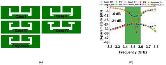
Figure 2.
(a) Design evolution (b) S-parameters of design evolution.
The final proposed E-shaped slot was achieved by combining the concepts from case I–III to come up with the final layout, with the desired center frequency of 3.5 GHz and a superior isolation level of 21 dB. Figure 2b shows the corresponding S-parameters obtained from the evolved E-shaped slot etched on the ground plane. Considering the plotted scattering parameters in Figure 2b, we can conclude that in the case of I to IV, the ground current effect is considerably less, leading to higher isolation. In the final proposed design, it is clear that the introduction of the bent sections resulted in shifting the center frequency to the desired one 3.5 GHz. However, the isolation level is less when compared to the previous cases I to IV. That is to say, the bent section has a direct effect on the S11 result. All the isolation levels are found to be below −21 dB. The result demonstrates that the proposed antenna is a suitable candidate to be employed in smartphone applications in the LTE frequency band 42.
Figure 3 shows the current distribution on the ground when Ant. 1 is energized while all others are terminated to 50-ohm impedance. A little current spreads across Ant. 2, which is non-desirable and leads to lowering the isolation level. For this reason, we employ an E-shaped resonator to restrict undesirable currents, as illustrated in Figure 3b. With no decoupling structure, the isolation is −19 dB, while the isolation improves to more than −21 dB with the decoupling structure. The advantage of the decoupling structure can further be deduced by looking at Figure 4a,b.

Figure 3.
Antenna surface current distribution at 3.5 GHz with Ant.1 excited (a) with no decoupling element and (b) with the decoupling element.
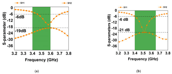
Figure 4.
Simulated S-parameter (a) with no decoupling element (b) with the decoupling element.
3. Results and Discussions
The proposed eight-element array antenna simulation results, such as parametric analysis, envelope correlation coefficient (ECC), S-parameters, overall efficiency, antenna gain, and radiation pattern, are presented in this section.
3.1. Parametric Analysis, S-Parameters, Gain, and Efficiency
Variations of some design parameters were investigated in this study. Figure 5a–e shows the plots of the scattering parameters as a dependent variable on L, t, d, g, and I, respectively. Sweeps were performed to validate the impact of the aforementioned factors on system performance. From Figure 5a, it is clear that with the initial parameter value of 15 mm, the first resonance is at 3.53 GHz, so also all other values remain at that frequency. The only effect here is that the magnitude of the resonance increases with an increase in the L value.
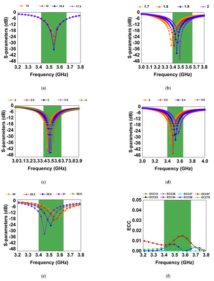
Figure 5.
Scattering parameter plots (a) parametric study of the parameter L (b) parametric study of t parameter (c) parametric study of d parameter (d) parametric study of g parameter (e) parametric study of I parameter (f) envelope correlation coefficient.
Figure 5b is a plot of t variation, which indicates how the frequency resonance varies with an increase in the t parameter. The resonance point moved toward the higher frequency band with an increase in the t value, so also the magnitude increased with the increase in the parameter. The variation of the d parameter in Figure 5c shows little effect when the value is varied from 2 to 4 mm; at an interval of 0.5. Similarly, the g parameter was also varied, and the effect can be seen in Figure 5d. Figure 5e shows the experimental results of the I-shape variation on the antenna frame. As can be seen from the simulated scattering parameters in Figure 5e, the S11 shifts to a lower resonance frequency with an increase in the length of the I parameter.
Figure 6a depicts both the simulated values as well as the measured reflection coefficient plot for Ant 1 through Ant 4. This work achieved a magnitude better than 18 dB for the four antennas, covering the (3.4–3.65) GHz. Figure 6b shows the port isolation plots between the neighboring antennas, for which we obtained isolation better than 21 dB in all possible combinations. From the depicted measured antenna efficiency in Figure 7a, it is clear that our system achieved an efficiency value between 34–76% within the frequency of interest with antenna 8 having the maximum efficiency of 70%. We consider the minimum and maximum efficiencies of the antennas as quoted in Table 2. Figure 7b indicates the gain of the antenna. A gain value higher than 3.1 dB is obtained with a maximum value of around 4.8 dBi. Note that the maximum value of the gain is quoted as provided in Table 2.
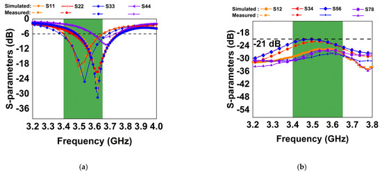
Figure 6.
Simulated and measured scattering parameters (a) reflection parameters and (b) transmission parameters value.
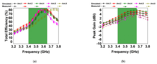
Figure 7.
Measured (a) antenna total efficiency and (b) antenna gain.
3.2. Radiation Performance
The 3.5 GHz band 2D radiation patterns for Ant. 1–4 are shown in Figure 8. The solid lines denote the simulated results, while the dotted lines are the measured results. It is quite evident that antenna 1–4, at both Φ = 90° and θ = 0°, have strong radiation in almost all the planes. Despite minor differences between the measured and simulated results, there is a general trend between the two findings, and the tiny discrepancy is related to the test settings. In conclusion, variation in maximum radiation orientations results in a diverse pattern, which contributes to the general diversity performance of the MIMO antenna.
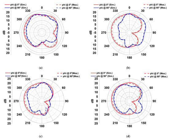
Figure 8.
Simulated and measured radiation patterns of the MIMO antenna at 3.5 GHz (a) Ant 1 θ = 0° and 90° (b) Ant 2 θ = 0° and 90° (c) Ant 3 θ = 0° and 90° (d) Ant 4 θ = 0° and 90°.
3.3. MIMO Channel Capacity and ECC
The channel capacity and envelope correlation coefficient are the key criteria for assessing a MIMO antenna diversity and multiplexing capability. Although zero is the ideal value for ECC, in practice the acceptable limit must be less than 0.5 (ECC < 0.5). The value of the ECC can be calculated from the S-parameter or from the far-field radiation pattern [29,30]. This work uses a far-field radiation pattern [31] to calculate the ECC value as expressed in [32,33] (1). From Figure 6f, this work obtained an ECC value lower than 0.01 across the desired band of interest. Figure 9 is the channel capacity plot of the design. The fabricated prototype and measurement set up is shown in Figure 10.
where and represent the radiation pattern when antenna and are energized, while is the solid angle.
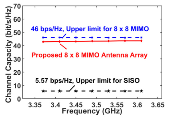
Figure 9.
Calculated channel capacity of proposed system.
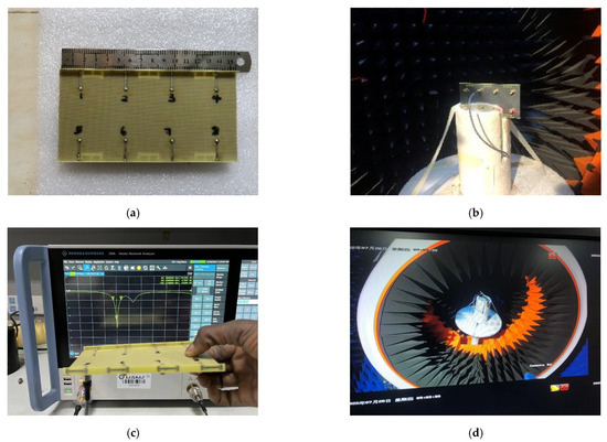
Figure 10.
(a) Proposed MIMO system fabricated prototype (b) measurement set-up (c) S-parameter measurement by the VNA (d) antenna under measurement in the chamber room.
The diversity gain plot of the antenna elements is shown in Figure 11, while Equation (2) is used to calculate the DG from the ECC value. It could be seen that for all the possible combinations, a gain of more than 9.99 dB is achieved over the operation band.
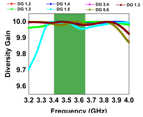
Figure 11.
Diversity gain.
Based on antenna efficiency and ECC, the ergodic channel capacity is obtained by averaging 100,000. Rayleigh fading channel realizations with the Kronecker channel model by considering SNR of 20 dB [34,35]. The value varies from 40.95 to 43.50 bps/Hz. The highest peak channel capacity (PCC) is (43.5 b/s/Hz), which is satisfactory in performance with SISO (5.57 b/s/Hz) and close in value for 8 × 8 MIMO (46 b/s/Hz). These values demonstrate unequivocally that the presented antenna system is suitable for use in 5G mobile terminal applications due to its high diversity and multiplexing capabilities. Figure 10 shows the proposed antenna fabricated prototype, far-field measurement set-up, S-parameters measurement using Vector Network Analyzer (VNA), and the antenna in the anechoic chamber room under measurement. From the obtained results, it can be easily concluded that the proposed design is highly competitive in comparison to the most recent advancements in this field, as presented in Table 2.

Table 2.
Comparison table.
Table 2.
Comparison table.
| Ref. | BW (GHz) | Sij (dB) | ECC | Eff. (%) | PCC (bps/Hz) | Elements | Gain (dB) |
|---|---|---|---|---|---|---|---|
| [1] | 3.4–3.7 (−6 dB) | >15 | <0.1 | 50–75 | 38.1 | 8 × 8 | 4 |
| [5] | 3.4–3.6 (−6 dB) | >12 | <0.1 | 47–65 | 37.5 | 8 × 8 | 3.2 |
| [14] | 3.4–3.6 (−6 dB) | >17.5 | <0.05 | 62–76 | 40.8 | 8 × 8 | Not Given |
| [18] | 3.4–3.6 (−6 dB) | >15 | <0.15 | 45–60 | 35 | 8 × 8 | 4.8 |
| [36] | 3.4–3.6 (−10 dB) | >19.1 | <0.012 | 59–98 | Not Given | 8 × 8 | Not Given |
| [37] | 3.4–3.6 (−10 dB) | >12.7 | <0.13 | 39–50 | Not Given | 4× 4 | Not Given |
| Proposed | 3.4–3.65 (−6 dB) | >21 | <0.01 | 34–76 | 43.5 | 8 × 8 | 4.8 |
4. Conclusions
In this paper, an eight-element antenna array incorporating an I-shaped frame and a modified E-slot etched on the ground is presented. The proposed antenna is simple to design and easy to fabricate. An impedance bandwidth of more than 250 MHz under −6 dB conditions is achieved in this work. The ECC for the entire frequency range is less than 0.01, and the level of element isolation is well below −21 dB. This work achieves these better performances since we etched the modified E-slot on the ground. The antenna system channel capacity obtained is 43.5 b/s/Hz, while the efficiency is more than 76%.
Author Contributions
Conceptualization, H.S.A. and Z.Z.; methodology, H.S.A., B.W. and S.H.K.; software, N.O.P. and Z.Z.; validation, B.H. and S.H.K.; formal analysis, N.O.P.; investigation, H.S.A.; resources, B.W. and B.H.; data curation, S.H.K. and N.O.P.; writing—original draft preparation, B.H. and Z.Z.; writing—review and editing, B.H. and B.W.; visualization, S.H.K. and B.W.; supervision, Z.Z.; project administration, Z.Z.; funding acquisition, Z.Z. All authors have read and agreed to the published version of the manuscript.
Funding
The Deanship of Scientific Research (DSR) at King Abdulaziz University, Jeddah, funded this project under grant no. RG-14-135-43.
Data Availability Statement
All data have been included in the study.
Acknowledgments
The authors are thankful to the Deanship of Scientific Research, King Abdulaziz University for providing financial support vide grant number (RG-14-135-43).
Conflicts of Interest
The authors declare no conflict of interest.
References
- Abdullah, M.; Altaf, A.; Anjum, M.; Arain, Z.; Jamali, A.; Alibakhshikenari, M.; Falcone, F.; Limiti, E. Future smartphone: MIMO antenna system for 5G mobile terminals. IEEE Access 2021, 9, 91593–91603. [Google Scholar] [CrossRef]
- Abdullah, M.; Kiani, S.H.; Abdulrazak, L.F.; Iqbal, A.; Bashir, M.A.; Khan, S.; Kim, S. High-performance multiple-input multiple-output antenna system for 5G mobile terminals. Electronics 2019, 8, 1090. [Google Scholar] [CrossRef]
- Abdullah, M.; Kiani, S.H.; Iqbal, A. Eight-element multiple-input multiple-output (MIMO) antenna for 5G mobile applications. IEEE Access 2019, 7, 134488–134495. [Google Scholar] [CrossRef]
- Kiani, S.H.; Altaf, A.; Abdullah, M.; Muhammad, F.; Shoaib, N.; Anjum, M.R.; Damaševičius, R.; Blažauskas, T. Eight element side edged framed MIMO antenna array for future 5G smartphones. Micromachines 2020, 11, 956. [Google Scholar] [CrossRef] [PubMed]
- Kiani, S.H.; Altaf, A.; Anjum, M.R.; Afridi, S.; Arain, Z.A.; Anwar, S.; Limit, E. MIMO Antenna System for Modern 5G Handheld Devices with Healthcare and High Rate Delivery. Sensors 2021, 21, 7415. [Google Scholar] [CrossRef] [PubMed]
- Huang, D.; Du, Z.; Wang, Y. A quad-antenna system for 4G/5G/GPS metal frame mobile phones. IEEE Antennas Wirel. Propag. Lett. 2019, 18, 1586–1590. [Google Scholar] [CrossRef]
- Sultan, K.; Ikram, M.; Nguyen-Trong, N. A Multiband Multibeam Antenna for Sub-6 GHz and mm-Wave 5G Applications. IEEE Antennas Wirel. Propag. Lett. 2022, 21, 1278–1282. [Google Scholar] [CrossRef]
- Lin, Z.; Niu, H.; An, K.; Wang, Y.; Zheng, G.; Chatzinotas, S.; Hu, Y. Refracting RIS aided hybrid satellite-terrestrial relay networks: Joint beamforming design and optimization. IEEE Trans. Aerosp. Electron. Syst. 2022, 58, 3717–3724. [Google Scholar] [CrossRef]
- Lin, Z.; An, K.; Niu, H.; Hu, Y.; Chatzinotas, S.; Zheng, G.; Wang, J. SLNR-based secure energy-efficient beamforming in Multibeam Satellite Systems. IEEE Trans. Aerosp. Electron. Syst. 2022. [Google Scholar] [CrossRef]
- An, K.; Lin, M.; Ouyang, J.; Zhu, W.P. Secure transmission in cognitive satellite terrestrial networks. IEEE J. Sel. Areas Commun. 2016, 34, 3025–3037. [Google Scholar] [CrossRef]
- An, K.; Liang, T.; Zheng, G.; Yan, X.; Li, Y.; Chatzinotas, S. Performance limits of cognitive-uplink FSS and terrestrial FS for Ka-band. IEEE Trans. Aerosp. Electron. Syst. 2018, 55, 2604–2611. [Google Scholar] [CrossRef]
- Lin, Z.; Lin, M.; De Cola, T.; Wang, J.B.; Zhu, W.P.; Cheng, J. Supporting IoT with rate-splitting multiple access in satellite and aerial-integrated networks. IEEE Internet Things J. 2021, 8, 11123–11134. [Google Scholar] [CrossRef]
- Chen, H.; Tsai, Y.; Kuo, C. Broadband eight-antenna array design for sub-6 GHz 5G NR bands metal-frame smartphone applications. IEEE Antennas Wirel. Propag. Lett. 2020, 19, 1078–1082. [Google Scholar] [CrossRef]
- Li, Y.; Luo, Y.; Yang, G. High-isolation 3.5 GHz eight-antenna MIMO array using balanced open-slot antenna element for 5G smartphones. IEEE Trans. Antennas Propag. 2019, 67, 3820–3830. [Google Scholar] [CrossRef]
- Chen, X.; Zhang, S.; Li, Q. A review of mutual coupling in MIMO systems. IEEE Access 2018, 6, 24706–24719. [Google Scholar] [CrossRef]
- Sun, L.; Li, Y.; Zhang, Z. Decoupling between extremely closely spaced patch antennas by mode cancellation method. IEEE Trans. Antennas Propag. 2020, 69, 3074–3083. [Google Scholar] [CrossRef]
- Wong, K.; Lu, J.; Chen, L.; Li, W.; Ban, Y. 8-antenna and 16-antenna arrays using the quad-antenna linear array as a building block for the 3.5-GHz LTE MIMO operation in the smartphone. Microw. Opt. Technol. Lett. 2016, 58, 174–181. [Google Scholar] [CrossRef]
- Jiang, W.; Liu, B.; Cui, Y.; Hu, W. High-isolation eight-element MIMO array for 5G smartphone applications. IEEE Access 2019, 7, 34104–34112. [Google Scholar] [CrossRef]
- Zhao, L.; Yeung, L.; Wu, K. A coupled resonator decoupling network for two-element compact antenna arrays in mobile terminals. IEEE Trans. Antennas Propag. 2014, 62, 2767–2776. [Google Scholar] [CrossRef]
- Li, M.; Jiang, L.; Yeung, K. Novel and efficient parasitic decoupling network for closely coupled antennas. IEEE Trans. Antennas Propag. 2019, 67, 3574–3585. [Google Scholar] [CrossRef]
- Lee, J.; Kim, S.; Jang, J. Reduction of mutual coupling in planar multiple antenna by using 1-D EBG and SRR structures. IEEE Trans. Antennas Propag. 2015, 63, 4194–4198. [Google Scholar] [CrossRef]
- Li, Z.; Du, Z.; Takahashi, M.; Saito, K.; Ito, K. Reducing mutual coupling of MIMO antennas with parasitic elements for mobile terminals. IEEE Trans. Antennas Propag. 2011, 60, 473–481. [Google Scholar] [CrossRef]
- Zhang, S.; Lau, B.; Tan, Y.; Ying, Z.; He, S. Mutual coupling reduction of two PIFAs with a T-shape slot impedance transformer for MIMO mobile terminals. IEEE Trans. Antennas Propag. 2011, 60, 1521–1531. [Google Scholar] [CrossRef]
- Sun, L.; Feng, H.; Li, Y.; Zhang, Z. Compact 5G MIMO mobile phone antennas with tightly arranged orthogonal-mode pairs. IEEE Trans. Antennas Propag. 2018, 66, 6364–6369. [Google Scholar] [CrossRef]
- Ding, C.; Zhang, X.; Xue, C. Novel pattern-diversity-based decoupling method and its application to multi-element MIMO antenna. IEEE Trans. Antennas Propag. 2018, 66, 4976–4985. [Google Scholar] [CrossRef]
- Xu, H.; Zhou, H.; Gao, S.; Wang, H.; Cheng, Y. Multimode decoupling technique with independent tuning characteristic for mobile terminals. IEEE Trans. Antennas Propag. 2017, 65, 6739–6751. [Google Scholar] [CrossRef]
- Ren, Z.; Zhao, A.; Wu, S. MIMO antenna with compact decoupled antenna pairs for 5G mobile terminal. IEEE Antennas Wirel. Propag. Lett. 2019, 18, 1367–1371. [Google Scholar] [CrossRef]
- Li, M.; Ban, Y.; Xu, Z.; Guo, J.; Yu, Z. Tri-polarized 12-antenna MIMO array for future 5G smartphone applications. IEEE Access 2017, 6, 6160–6170. [Google Scholar] [CrossRef]
- Sharma, P.; Tiwari, R.N.; Singh, P.; Kumar, P.; Kanaujia, B.K. MIMO Antennas: Design Approaches, Techniques, and Applications. Sensors 2022, 22, 7813. [Google Scholar] [CrossRef]
- Peng, H.; Zhi, R.; Yang, Q.; Cai, J.; Wan, Y.; Liu, G. Design of a MIMO antenna with high gain and enhanced isolation for WLAN applications. Electronics 2021, 10, 1659. [Google Scholar] [CrossRef]
- Sharawi, M.S.; Hassan, A.; Khan, M.U. Correlation coefficient calculations for MIMO antenna systems: A comparative study. Int. J. Microw. Wireless Technol. 2017, 9, 1991–2004. [Google Scholar] [CrossRef]
- Agarwal, S.; Rafique, U.; Ullah, R.; Ullah, S.; Khan, S.; Donelli, M. Double Overt-Leaf Shaped CPW-Fed Four Port UWB MIMO Antenna. Electronics 2021, 10, 3140. [Google Scholar] [CrossRef]
- Zahid, M.N.; Gaofeng, Z.; Kiani, S.H.; Rafique, U.; Abbas, S.M.; Alibakhshikenari, M.; Dalarsson, M. H-shaped eight-element dual-band MIMO antenna for sub-6 GHz 5G smartphone applications. IEEE Access 2022, 10, 85619–85629. [Google Scholar] [CrossRef]
- Tian, R.; Lau, B.; Ying, Z. Multiplexing efficiency of MIMO antennas. IEEE Antennas Wirel. Propag. Lett. 2011, 10, 183–186. [Google Scholar] [CrossRef]
- Ali, H.; Ren, X.-C.; Hashmi, A.M.; Anjum, M.R.; Bari, I.; Majid, S.I.; Jan, N.; Tareen, W.U.K.; Iqbal, A.; Khan, M.A. An eight-element dual band antenna for future 5G smartphones. Electronics 2021, 10, 3022. [Google Scholar] [CrossRef]
- Zhao, A.; Ren, Z. Size reduction of self-isolated MIMO antenna system for 5G mobile phone applications. IEEE Antennas Wirel. Propag. Lett. 2018, 18, 152–156. [Google Scholar] [CrossRef]
- Chang, L.; Yu, Y.; Wei, K.; Wang, H. Polarization-orthogonal co-frequency dual antenna pair suitable for 5G MIMO smartphone with metallic bezels. IEEE Trans. Antennas Propag. 2019, 67, 5212–5220. [Google Scholar] [CrossRef]
Disclaimer/Publisher’s Note: The statements, opinions and data contained in all publications are solely those of the individual author(s) and contributor(s) and not of MDPI and/or the editor(s). MDPI and/or the editor(s) disclaim responsibility for any injury to people or property resulting from any ideas, methods, instructions or products referred to in the content. |
© 2023 by the authors. Licensee MDPI, Basel, Switzerland. This article is an open access article distributed under the terms and conditions of the Creative Commons Attribution (CC BY) license (https://creativecommons.org/licenses/by/4.0/).