Article

3D-Printed Dielectric Rods for Radar Range Enhancement

Department of Electrical and Computer Engineering, University of Waterloo, Waterloo, ON N2L 3G1, Canada
*
Author to whom correspondence should be addressed.
Electronics 2023, 12(19), 4016; https://doi.org/10.3390/electronics12194016
Submission received: 20 July 2023 / Revised: 1 September 2023 / Accepted: 21 September 2023 / Published: 23 September 2023
(This article belongs to the Special Issue Advanced Topics in Modelling Microwave and mmWave Electron Devices)

Abstract

:
A design strategy to alter the radiation characteristics of modular radar printed circuit boards without the need for expensive retooling and remanufacturing is presented in this paper. To this end, a compact radar module including microstrip array antennas integrated with a dielectric rod lens is considered for a demonstration of an X-band radar antenna gain improvement leading to radar detection range enhancement. Using travelling wave theory, the proposed lens is designed to target the excitation of HE11 mode to achieve gain improvement without disturbing reflection coefficients. Using a low-cost rapid-manufacturing 3D-printing technology, two pairs of the 3D-printed dielectric rods integrated with a dielectric housing are designed and fabricated uniformly for a commercially available off-the-shelf radar module. The radar integration with the dielectric rod lens leads to a low-cost and easy-to-fabricate long-range radar system. Compared with the radar without the rods, the design system achieved a measured 6.6 dB gain improvement of the transmitter and receiver antennas which causes doubling the detection range for both elevation and azimuth directions at 10.525 GHz.

1. Introduction

Recently, the demand for using automotive radars in high-performance applications with a high level of integration, low fabrication costs, and high gain has increased [1]. Many off-the-shelf radar modules are commercially available, providing compactness and cost savings, utilized in contactless sleep sensing systems [2], gait and in-home activity monitoring [3], moving road user object detection [4], and human–vehicle detection sensors [5]. The currently available modules demonstrate suitability for certain applications; nonetheless, they lack a tailored design to cater to specific applications that necessitate expanded coverage or a divergent field of view.
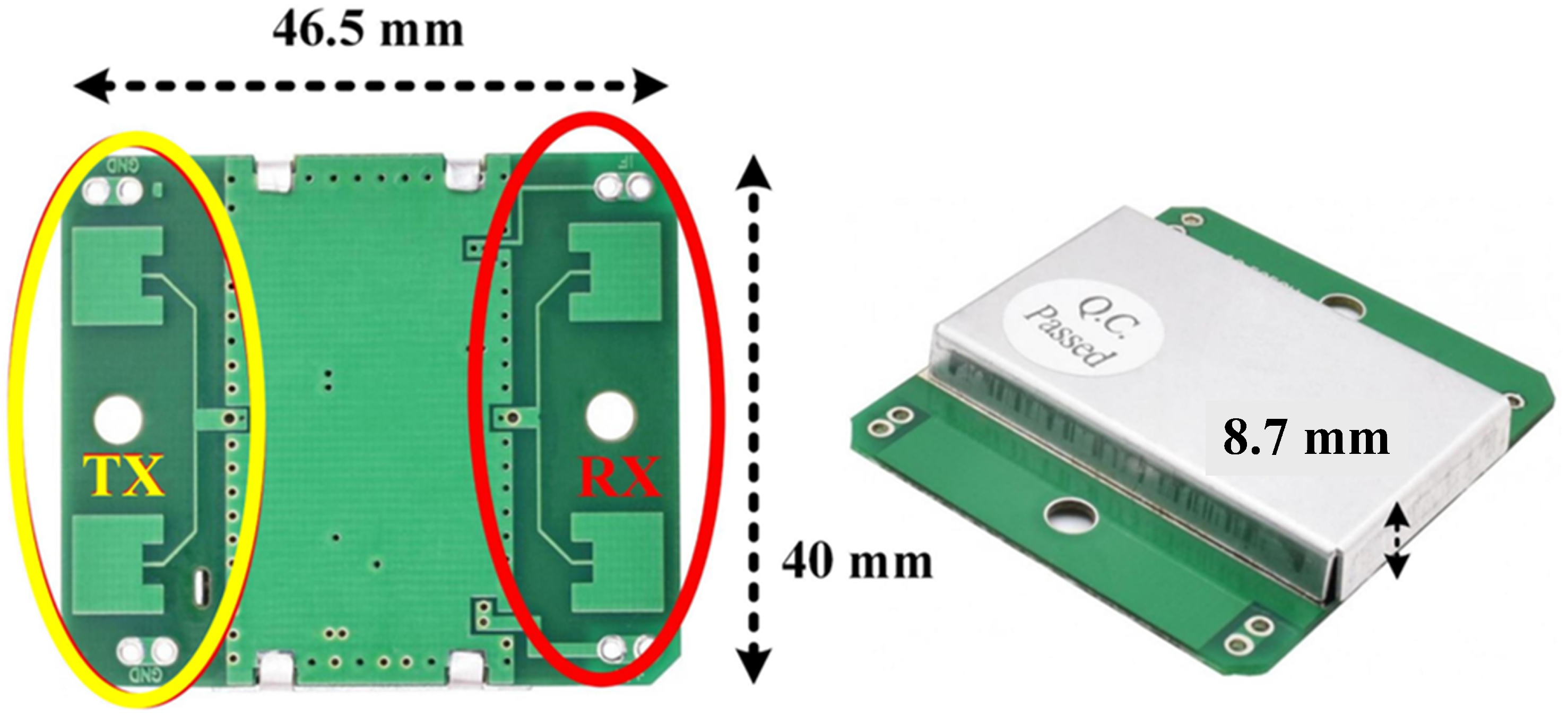
Continuous-wave radars, which are widely employed in various commercial off-the-shelf radar systems, are commonly utilized to measure the velocity of a mobile entity at a specific distance based on Doppler shifts. The X-band HB100 Doppler radar module, known for its popularity, accuracy, and affordability, finds extensive utilization in a range of applications such as automatic door startup, car/house intrusion alarm systems, collision warning systems, and traffic monitoring [6]. A limitation of this radar system is its restricted detection range, as it is capable of detecting vehicles up to a maximum distance of approximately 7 m [7].
Most of the radar module designs include the radar chipsets and the transmitter/receiver antennas which are implemented in a printed circuit board (PCB), using on-chip or on-PCB antennas. In the context of such systems, it is imperative for the antenna to possess a compact form factor to facilitate seamless integration while simultaneously delivering high gain to ensure an extended detection range and high efficiency to prevent power loss. Conventionally, this necessitates distinct antenna design to achieve a varying antenna gain or pattern that typically entails a complete overhaul of the integrated antennas and subsequent remanufacturing of the radar module, leading to substantial associated expenses.
Numerous methodologies are suggested to enhance the gain of printed circuit board (PCB) antennas employed in radar modules [8,9]. A prevalent technique involves the utilization of an array configuration where multiple antennas, positioned at a specific separation distance, are excited by a feeding network [10]. Nevertheless, employing this method leads to the design profile complexity and cost accompanied by the introduction of additional losses.
Superstrate designs incorporating Fabry–Perot resonators and metamaterial theory present promising approaches in different applications for gain enhancement [11]. In [12], a dielectric parallel-plate metamaterial waveguide including nine dielectric FR-4 plates with λ /4 airgap is placed above the transmitter and receiver of an HB100 radar antenna separately. The overall gain enhancement of 5.5 dB is obtained for the transmitter and receiver antenna. In [13], an array of patch antennas covered by a flat high-refractive-index metamaterial provided 3.4 dB gain improvement. However, these gain enhancement methods necessitate intricate and costly designs, as well as high-profile structures; otherwise, they offer only marginal improvements in gain, rendering them unsuitable for long-range detection radars.
The integration of lens antennas with microstrip antennas is an alternative approach employed in automotive radar applications to enhance antenna capabilities, including the facilitation of polarization rotation [14] and beam scanning [15]. Recently, dielectric and metallic lens antennas indicate great potential in gain improvement [1,16,17]. The benefits associated with the utilization of lens antennas include the straightforwardness of the design, increased resilience to variations in production parameters, enhanced efficiency due to reduced mutual coupling, and the often sufficient usage of a single element, such as a patch or slot antenna, positioned at the focal point of the lens as a feeder.
In [1], a 24 GHz system-on-package is presented, which incorporates a fractal antenna array with an integrated grooved Fresnel lens with a total dimension of 2 λ × 2 λ × 0.38 λ mm2. The system occupies 19 layers of CT765 substrate with a dielectric constant of 68.7 and enhances the system gain by 6 dB. In situations where TX/RX antennas are situated on a PCB board, the application of such lenses is unsuitable due to potential beam tilting errors. A 77-GHz planar lens array on dual-layer PCB is proposed in [16] for automotive radar applications. Combining the lens with four SIW slot antennas as the primary feeds provides a gain improvement of 15 dB at 76.5 GHz. Although the planar array structure known as transmitarray can be used as a lens, it has a large square dimension of 10.3 λ , with poor aperture efficiency of 19.3 which is not a suitable method in the case of having TX/RX antennas in one feeder plate [17]. The design of a feeder in the form of a 2 × 2 patch array combined with a commercially available hyperbolic dielectric lens is presented in [18]. While the lens leads to 15.7 dB gain improvement, it has a large dimension with a diameter of around 19 λ , a thickness of 3.3 λ , placed above the patch array antenna with an air gap distance of 11.48 λ . In [19], a hyperbolic lens antenna is designed and fabricated for an mm-wave MIMO radar operating at 77 GHz, providing more than 12 dB gain improvement. However, the relatively large dimension of the lens antennas is challenging at lower frequency bands. To place a lens closer to the feeder for a low-profile design, the thickness of the lens should be increased, leading to a heavy and high-profile structure causing multiple reflections between the feeder and lens surface. On the other hand, using a thinner lens far away from the feeder causes too much spillover with a very-high-profile design [18].
In general, the lens structures investigated in the literature exhibit certain limitations, including high-profile configurations, intricate designs, and significant challenges associated with manufacturing and integration into the radar module. Given some attractive attributes such as lightweight, low-profile, and being cost-effective to fabricate, dielectric rods, commonly referred to as end-fired surface-wave antennas, are gaining popularity in a wide range of applications [20], such as Directivity enhancement of printed antennas for high-data-rate wireless communications [21,22], high-gain omnidirectional antenna [23], and aperture efficiency improvement of the space-fed antennas [24].
The utilization of dielectric rods as loadings or lenses for diverse antenna types, such as metallic waveguides [20], microstrip patch [21], and radar PCB antenna-on-chip [25], offers a compact and lightweight structure that enables enhancements in gain as well as reductions in cross-polarization and side-lobe levels. Ref. [21] introduces a V-band antenna consisting of a patch-fed dielectric rod. The dielectric rod, fabricated using Teflon through a CNC machine, is positioned on top of the patch to produce complex mode excitations. To convert the mode from the patch and eliminate undesired modes during radiation, an additional design incorporating a metallic cylindrical waveguide is implemented at the base. The additional height of the circular waveguide is set to 1.42 λ , resulting in a total length of 6.71 λ while yielding a 16 dB gain at 61 GHz. In [22], three arrays of multiple dielectric rods with airgaps in between are designed by high-permittivity material ( ϵ r = 9.8) placed in parallel to a patch antenna. This design provides an EBG-type superstrate to enhance directivity up to 8 dB compared to an isolated patch antenna. In [23], a lens consisting of 16 periodic aluminium rods attached to the aluminium plates is proposed to enhance the gain of an omnidirectional cylindrical radiator at 920 MHz, providing an overall gain of 19.47 dB. However, The dielectric rod structures discussed in these studies employ intricate design methodologies, expensive fabrication processes involving high-permittivity dielectric materials or complex metal shaping, and face difficulties when it comes to integrating them with the primary feeder.
Recently, the adoption of 3D-printing, a cost-effective and straightforward manufacturing technique, has gained prominence for fabricating dielectric rods [26]. This method enables the uniform fabrication of arbitrary rod structures according to specific requirements. As reported in [27], the 3D-printing-based manufacturing process is an efficient solution for designing high-performance dielectric lens antennas.
This paper enables guidelines for a simple and low-cost design strategy for an optimum array size based on dielectric rods. The proposed design transfers a low-cost short-range HB100 radar system to a low-cost long-range radar for bicycle collision warnings application without having to redesign the PCB module. The minimum number of dielectric rods tapered in a conical shape, one for each radiator, is considered to provide a low-profile lens structure. The uniform fabrication using 3D-printing technology with no additional materials is utilized for a low-cost clip-on dielectric rod lens that helps to quickly change the radar module radiation characteristics. The proposed lens integrated with the microstrip patch feeder provides more than double the working range of the radar module as a result of 6.6 dB gain enhancement for TX and RX antennas, separately.
Due to typical fabrication errors and instability of the dielectric constant of the 3D-printed material against the filling process, the sensitivity analysis of design parameters is also performed to determine their effects on the resonant frequency and gain. In Section 2, the design strategy of the dielectric rod lens for the HB100 radar module is presented. In Section 3, the designed dielectric rod integrated with the radar module is investigated and simulation results are derived and compared for radar modules with and without dielectric rod lenses. Subsequently, within this section’s continuation, the process of fabrication, measurements, and manufacturing sensitivity analysis are addressed. Section 4 explores the discussion for the presented methodology, while a conclusion is drawn based on the findings in Section 5.

2. Dielectric Rod Lens Design for Radar Module

This section focuses on designing the configuration of a 2 × 2 dielectric rod array as an integrated lens aiming to enhance the gain of the HB100 radar module.

2.1. Doppler HB100 Radar Module

The Doppler effect is harnessed by a radar system to detect alterations in the velocity of objects at a specific range by bouncing a microwave signal off a desired target. The X-band HB100 Doppler radar, one of the popular, accurate, and affordable modules, is widely employed in various applications such as automatic door startup, car and house intrusion alarms, collision warning, and traffic monitoring [28].
The structure of the selected radar is shown in Figure 1. As seen, the radar PCB consists of two pairs of 1 × 2 arrays of a rectangular microstrip patch antenna as a transmitter and a receiver antenna. The total rectangular dimension is 40 × 46.5 mm, printed on the FR-4 substrate with a thickness of 0.8 mm. Based on the simulation, the proposed antennas provide 6.5 dB realized gain separately. According to the datasheet, the radar has a detection range coverage of 20 m. However, this detection range works properly for a vehicle at a close range of about 7 m at the center frequency of 10.525 GHz [7]. The objective of this study is to enhance the detection range of the HB100 module for the purpose of mitigating potential collisions involving cyclists. Without modifying the structure of the radar module itself, we propose the utilization of dielectric rod lenses as a means to achieve this improvement.

2.2. Dielectric Rod Lens Design

The dielectric rod, which belongs to the category of travelling surface wave antennas, functions as a dielectric waveguide, leading to the emission of radiation at points of discontinuity [20]. The hybrid HE11 mode, a proper combination of TE and TM modes, is the dominant mode exhibited by the dielectric rod which generates equiphase electric fields with no cut-off frequency [20].
The dielectric constant of the rod structure imposes limitations. It can be shown that matching the dielectric rod with low-permittivity materials requires a large dimension and complicated design. Given that low-cost materials commonly employed in 3D-printing machines typically exhibit low permittivity, ( ϵ r = 2.5 in the X-band), a compromise must be established between the maximum feasible size and the subsequent enhancement in gain. The gain of the rod is influenced by its length, emphasizing the importance of this parameter. Additionally, the mode conversion process is significantly affected by the shape and dimensions of the rod’s cross-section [29].
The widely adopted rod structures commonly exhibit circular or rectangular cross-sections with a uniform or tapered body supporting surface wave modes. As reported in [30], the utilization of a dielectric rod with a circular cross-section offers several advantages, including a symmetric radiation pattern, wider bandwidth, low cross-polarization, and a simple design that allows for greater flexibility.
To ensure a seamless and efficient transition from patch radiation to the HE11 mode, as well as from the HE11 mode to a plane wave, careful consideration must be given to the diameter of the rod’s cross-section. By appropriately selecting the diameter, one can achieve a smooth and uninterrupted propagation of electromagnetic waves, optimizing the transmission of energy between these different modes. As reported in [30], the HE11 mode exhibits minimal loss over a broad range of diameters. Furthermore, the increased rod diameter induces a slow-wave effect, leading to more localized field confinement within the rod. As presented in [21], the fundamental HE11 mode can be excited in a circular dielectric rod by considering a rod diameter of at least 0.58 λ d ( λ d is the wavelength in a dielectric rod). Therefore, a proper diameter-to-wavelength ratio guarantees the HE11 mode excitation. Considering the mutual coupling between the radar antennas, the bottom cross-section diameter is approximately considered 0.78 λ d (Rl = 14 mm) to match the highest radiated power from the patch in free space to the surface wave. On the other hand, the field profile of the HE11 mode is extended by reducing the rod diameter at the radiation end that should be tapered in the dielectric rod body.
The introduction of longitudinal tapering in the rod enhances the radiation characteristics by facilitating radiation along the entire length of the taper, resulting in improved performance [11]. The nontapered cylindrical dielectric rod propagates with the sum of the radiation from discontinuities which provides low gain and high side-lobe levels due to the interference between the ends and free space. Conversely, in tapered rods, power is leaked through the tapered profile, and the radiated power comprises the cumulative effect of radiation originating from the leaky wave structure [30]. Therefore, it is crucial for the tapering process to be conducted gradually in order to mitigate higher-order coupling effects and minimize fabrication complexities. In light of this, various types of tapered profiles are investigated, revealing negligible discrepancies among the outcomes. Consequently, a linear taper is favoured for its ease of fabrication and minimal errors when employing a 3D-printing machine.
Upon choosing the appropriate tapering profile, the top cross-section, denoted as Rs, needs to be optimized in order to achieve improved matching with free space. The sensitivity analysis yields an optimal value for each design parameter, ensuring an appropriate and suitable amount for their respective contributions. It can be shown that the top cross-section with a diameter of 0.45 λ d (Rs = 8 mm) connected to the bottom cross-section through a smooth linear tapering provides an optimized structure with enhanced performance and suitability as a lens for the patch antenna.
In [29], a direct relationship between the gain and the length of the antenna integrated with the tapered dielectric rod is derived:
G m a x = 10 h λ
Using (1), one can find the optimum gain of the tapered rod in terms of length. Alternatively, in order to achieve a double detection range for both the transmitter and receiver antenna independently, it is necessary to determine the desired gain improvement and subsequently determine the optimal length of the dielectric rod using (1). To obtain the desired gain improvement, the radar equation presented in [31] is used. The intensity of the received power P R X is calculated as
P R X = σ λ 2 P T X G T X G R X ( 4 π ) 3 R 4
where P T X is the transmitter power, R is the detection range, λ is the wavelength of the transmitted signal, σ is the radar cross-section, and G R X and G T X are the gain of the receiver and transmitter antenna, respectively. Regarding the proposed measurement setup used in [19], P T X , λ , and σ remain constant across all angles. In this case, R, G R X and G T X are the effective ones in (2). Assuming a stable received power P R X , it can be shown that
K = G T X G R X R 4 R = K 1 ( G T X G R X ) 1 4
where K and K 1 are constants at all angles.
Equation (3) clearly demonstrates that a 6 dB gain improvement at both the transmitter and receiver antennas corresponds to a fourfold increase in their respective gains, resulting in the doubling of the detection range. By conducting a full-wave simulation, it was determined that the individual gain of the TX/RX antenna in the HB100 radar module is 6.7 dB. Thus, achieving a gain of 12.7 dB should be adequate to fulfil the specified requirement. Based on this analysis, the minimum length of the tapered dielectric rod antenna can be determined using (1), resulting in a value of h = 1.8 λ . According to theoretical considerations, increasing the length of h leads to greater gain enhancement of the radar antenna. However, there exists a limitation on how much the length can be increased, which is dependent on the operating frequency. Furthermore, extending the taper length results in the emergence of higher side lobes and higher-order modes, which can introduce detrimental effects on the radiation characteristics of the antenna. To mitigate the detrimental effects and strike a balance between achieving the desired gain and maintaining structural compactness, this paper proposes an optimized length for the dielectric rod of 2 λ , corresponding to 60 mm. This choice aims to ensure an optimal compromise between these competing factors. The structure of the dielectric rod lens integrated with the radar module is presented in Figure 2.
The design of the lens is intricately linked to the specific application, as well as the dimensions and shape of the radar system being considered. The structure of the desired X-band HB100 radar module, as shown in Figure 1, includes two pairs of 1 × 2 microstrip patch arrays as a receiver and a transmitter. Consequently, an effective approach to modeling a lens involves employing four identical tapered dielectric rods positioned at the center of each patch, as illustrated in Figure 2a, which are positioned at an appropriate distance above each microstrip patch antenna.
In order to avoid unexpected modes and effectively mitigate their impact through supplementary design measures, a compact and low-profile lens based on the principles of Fabry–Perot (FP) theory is introduced. Following FP theory, it is determined that a 0.5 λ air gap between the patch antenna and the lens is adequate to stimulate the dielectric rod and enhance the gain of the patch antenna [9]. This specific gap distance is considered to maximize power reception from the patch radiation and facilitate optimal excitation of surface waves. To achieve this, dielectric housing is utilized as a foundation to maintain the rods at the desired distance from the radar chipset’s surface. The integrated structure is fabricated uniformly using a 3D-printing machine, ensuring consistent performance throughout.
The compact lens is formed by integrating the four dielectric rods with a dielectric housing, which encompasses the proposed HB100 radar module, as depicted in Figure 2b (the dotted line). This configuration results in a compact lens with overall dimensions measuring 50 × 60 × 60 mm. The values of the design parameters are presented in Table 1. The parameter “St” is the distance between two patches in the transmitter or receiver section, while the parameter “Str” shows the distance between the TX and the RX patches. Sufficient space is maintained between the dielectric rods to ensure low mutual coupling, with a separation distance between the two TX/RX arrays set at 3 λ / 2 .

3. Radar System Integrated with Dielectric Rod Lens

In this section, a comprehensive full-wave simulation using the HFSS simulator is conducted. The resulting outcomes cover mode analysis, impedance matching, coupling factors, and radiation gain patterns, which are subject to detailed examination. The fabrication configuration involves an array of dielectric rods, thoughtfully engineered to operate as an integrated compact lens system. This configuration is seamlessly integrated with the HB100 radar module, aiming to enhance the radar detection range capability.

3.1. Simulation Results

In this section, the dielectric rod lens provided in the study is modeled through established full-wave simulation tools; Ansys HFSS is utilized for both design and optimization purposes, while CST is employed to validate the obtained results. These simulations entail utilizing the physical dimensions outlined in design Section 2.2, which are subsequently optimized to achieve advantageous results. The results of these simulations are graphically represented in Figure 3, Figure 4, Figure 5 and Figure 6, illustrating aspects such as the distribution of the electric field on the dielectric rod, E-, and H-plane gain patterns, gain variations concerning frequency changes, and the lens’s impedance matching characteristics.
By utilizing a dielectric rod as a lens, the radiation of the patch antenna couples a portion of the input power into a surface wave, producing a hybrid mode, which travels along the rod structure and subsequently radiates into the surrounding free space. The presence of the excited HE11 mode, characterized by a zero cut-off frequency, results in an equiphase electric field configuration. This arrangement contributes to the enhancement of gain by concentrating the radiation field. To confirm the successful radiation of the HE11 mode within the designed dielectric rod, an investigation is conducted into the field distribution within the proposed rod. As depicted in Figure 3, the electromagnetic fields predominantly concentrate within the dielectric material, while the antenna exhibits radiation in the direction of the rod. The analysis of the electric field further indicates that employing a tapering profile for the dielectric rods results in a gradual and seamless increase in radiation, reaching its maximum intensity at the end of the structure.
The radar circuit incorporating transmitter and receiver patch antennas is printed on the FR-4 layer, while the dielectric rod lens is constructed using ABS, a material compatible with 3D-printing machines, offering both structural stability and desirable radiation specifications. When designing a system that incorporates 3D-printed materials, it is crucial to ensure the precise determination of the electromagnetic properties, thereby maintaining accurate and reliable performance. Using the X-band waveguide approach in the measurement process, ABS material was measured to have a permittivity of 2.53 and loss tangent of 0.004, which provides lower loss compared to PLA with permittivity of 2.52 and loss tangent of 0.022 [30].
By conducting a full-wave simulation, the 2D radiation pattern of the radar transmitter microstrip antenna is obtained and compared with and without the presence of the dielectric rod lens, as shown in Figure 4. It is evident that the dielectric rod lens enhances the realized gain of the TX/RX antenna by approximately 6.6 dB in both the E-plane and H-plane patterns. In accordance with the reciprocity theorem, the functionality of an antenna remains consistent, irrespective of whether it is employed as a transmitter or receiver. The placement symmetry observed in radar antennas leads to an identical radiation pattern for both the transmitter (TX) and receiver (RX) antennas. Furthermore, when incorporating the dielectric rod, the radiation patterns of both the transmitter and receiver antennas continue to exhibit identical characteristics. This is accomplished through the implementation of a symmetric dielectric rod array, a critical aspect in radar systems that feature collocated transmitter and receiver antennas.
To increase the detection range of a radar system, overlapped radiation patterns of transmitter and receiver antennas lead to a better long-range detection system. In contrast to other lens antennas designed in previous studies, where the coverage of both transmitters and receivers resulted in nonoverlapping patterns of the transmitter and receiver antennas [32], the proposed structure ensures that the patterns of both the transmitter and receiver antennas are directly aligned at the same angle.
The gain variation versus frequency for the radar antenna integrated with and without the dielectric rod lens is investigated in Figure 5. Since the dielectric rod is known as a travelling wave antenna, it can provide a wide gain bandwidth for the feeder antenna. Hence, as depicted in Figure 5, it is evident that despite the dielectric rod lens being excited by the patch radiation at a cut-off frequency of 10.525 GHz, the gain enhancement is attained within the frequency range of 8.2 to 12 GHz. In addition, Figure 5 shows that the maximum gain for the TX/RX antenna without the lens is 6.7 dB while the dielectric rod lens increases it to 13.3 dB.
The reflection coefficient as well as mutual coupling for both transmitter and receiver antennas integrated with and without dielectric lens are investigated and shown in Figure 6. The results indicate that the designed dielectric rod lens has no substantial impact on the primary performance of the patch antennas.

3.2. Fabrication and Measurement Process

Regarding the fabrication process of the dielectric rod, the common materials for 3D-printing include ABS, PLA, and their various blends. More sophisticated FDM printers can also work with specialized materials that offer properties such as enhanced heat resistance, impact resistance, chemical resistance, and rigidity. The proposed dielectric rod lens is constructed using ABS, a material well suited for 3D-printing machines, providing structural stability and favorable radiation properties, as discussed in Section 3.1.
A prototype of the fabricated HB100 radar chipset antenna integrated with and without the tapered dielectric rod lens is presented in Figure 7. To evaluate the effectiveness of the proposed system in enhancing radar range detection, the designed structure is mounted on the rear of a bicycle, allowing for practical measurement and assessment with an overall dimension of 50 × 60 × 74.8 mm.
The measurement setup depicted in Figure 7 shows that the radar detection range is evaluated in the cases of the radar module integrated with and without the dielectric rod lens. As previously stated, the objective of this paper is to quadruple the detection range of the HB100 radar module by increasing the gain of the transmitter and receiver antennas. According to (3), it is evident that a 6 dB gain improvement at both transmitter and receiver antennas means that the TX and RX antennas’ gains increase four times leading to the double detection range, separately. Hence, in the proposed system, a gain improvement of 6.6 dB for both the TX and RX antennas is deemed satisfactory to fulfil this requirement. Measurement results confirm that the HB100 radar integrated with the dielectric rod lens located at the back of a bicycle (Figure 7) increases the detection range twice for TX and RX antennas, separately.

3.3. Manufacturing Sensitivity Analysis

In this section, the outcomes of the parameters’ sensitivity analysis are discussed and any variations observed are highlighted.
For the fabrication process, it is essential to realize how sensitive the gain numbers are to any of the design parameters reported in Table 1. This analysis enables an understanding of how manufacturing tolerances will impact the final results. As summarized in Table 2, it demonstrates that the gain of the transmitter and receiver antennas remains constant by considering the maximum acceptable variations of each design parameter.
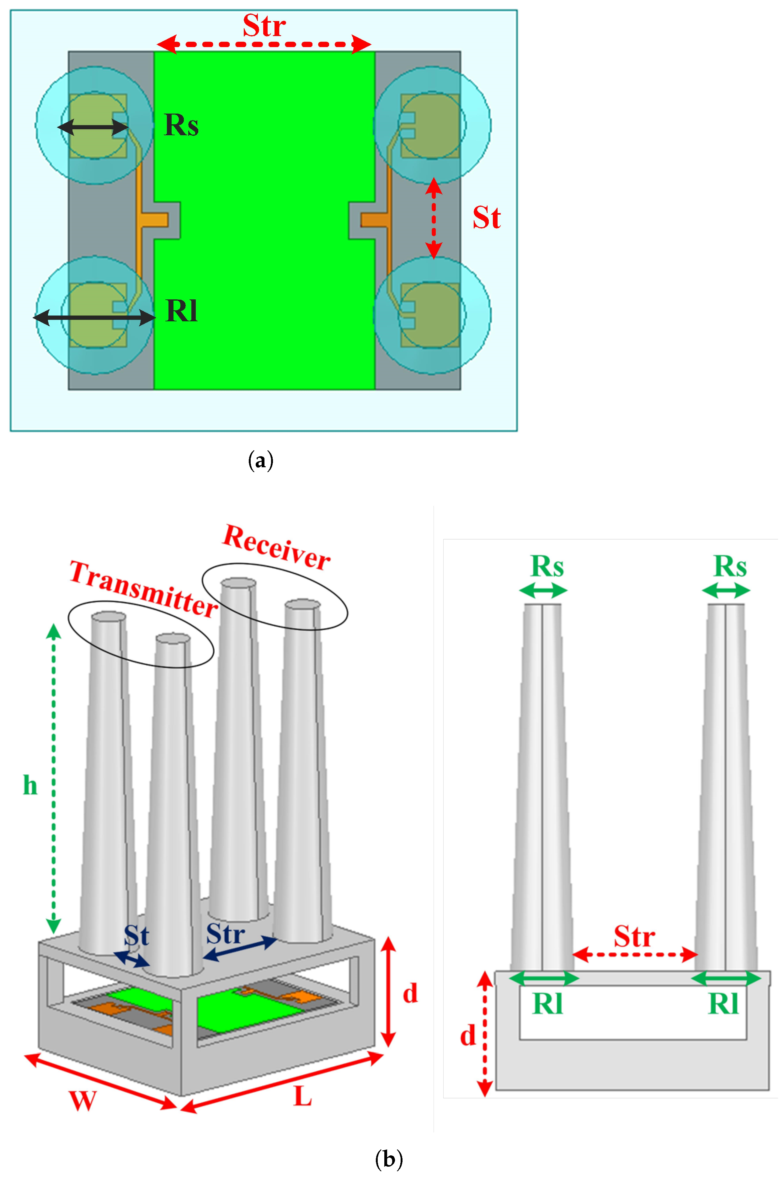
It can be observed that increasing the cross-sections’ diameter, Rs and Rl, has a greater impact on reducing the gain. The investigation of the top cross-section diameter variations shows that increasing Rs by more than 1 mm or decreasing it by more than 2 mm leads to a gain reduction of up to 1 dB. The investigation of the bottom cross-section diameter variations indicates that increasing Rl by more than 1.5 mm or decreasing it by more than 1 mm leads to the gain reduction gradually up to 1.8 dB.
The distance between the lens and the ground plane of the radar microstrip antenna plays a critical role in achieving significant gain improvement, ensuring proper matching at the center frequency, and minimizing mutual coupling. It can be observed that altering the distance, d, by 1 mm upward or 2 mm downward produces a consistent gain. Conversely, a gradual increase or decrease in distance from 1 to 5 mm causes a maximum gain reduction of 1 dB due to the activation of higher-order modes rather than HE11 mode in the dielectric rod. Reducing the optimal distance by over 5 mm causes significant mismatching, resulting in disruptive impacts on the reflection coefficient and a decrease in the achieved gain of no less than 3 dB.
The impact of rod length on gain variations is also investigated, revealing that increasing the length, h, by less than 20 mm or decreasing it by less than 5 mm yields acceptable variations without any reduction in gain. Despite the theoretical expectation of gain enhancement with increasing rod length, a rise in h by more than 20 mm does not result in substantial gain improvement. This lack of improvement is attributed to the emergence of higher side lobes and higher-order modes. Conversely, a reduction in rod length by more than 5 mm leads to a gradual decline in gain. For instance, at Δh = −1 cm, the gain is reduced by 1 dB.
The distance between four dielectric rods is also a significant parameter as it relates to the patch antenna’s location and needs to be considered in the design process with the specific aim of minimizing mutual coupling and enhancing matching performance. Based on sensitivity analysis, the study reveals that increasing the distance, Str, between the transmitter and receiver rods up to 5 mm has no discernible effect on the antenna gain; similarly, reducing the distance by up to 1.5 mm results in a safe and acceptable variation. Conversely, modifying the distance, Str, by decreasing it up to 5 mm or increasing it up to 10 mm results in a gain reduction exceeding 2 dB. The investigation of parameters St and Sr, which represent the distance between the transmitter and receiver rods, demonstrates that increasing St/Sr by 2 mm or decreasing it by less than 1.5 mm does not have a noticeable effect on the antenna gain. However, when St/Sr is increased by 5 mm or decreased by 3 mm, a reduction in gain of 0.3 dB and 1 dB is observed, respectively.
The final challenging aspect related to the material used in 3D-printing technology is the dependence of the dielectric constant on both the fabrication process and the operational temperature. Through our investigation, taking into account the ambient room temperature, it is determined that the overall gain remains constant within the range of dielectric constants from 2 to 2.8. However, for a dielectric constant of 3, a reduction in gain of 1 dB is observed, while for a dielectric constant of 1.8, the gain experiences a decrease of 1.2 dB.

4. Discussion

The complete process, encompassing the main steps such as design, simulation, and fabrication, is visually outlined in a flowchart, as depicted in Figure 8, that is essential for the comprehension of the technique.
The methodology presented in this paper for designing a dielectric rod array with enhanced gain functionality is applicable to any type of PCB antenna operating at different frequencies. This adaptability allows for smooth integration with commercially available radar modules, resulting in an enhanced radar detection range without necessitating alterations to the existing antenna design or production process. The 3D-printing technology provides an easy-to-fabricate and low-cost approach to manufacturing the dielectric rod and module housing uniformly to reduce fabrication errors and align the achieved results with the anticipated outcomes from the simulation. Furthermore, the presented lens structure is characterized by its low-profile and compact features. Upon integration with the radar module, the lens’s incorporation does not lead to an increase in the dimensions of the radar chipset in terms of length and width.
The results of the sensitivity analysis and gain pattern prove that using a 3D-printed dielectric rod is an efficient, easy-to-fabricate, and low-cost gain improvement method for the microstrip PCB antennas utilized in the off-the-shelf radar modules. The results achieved with the proposed lens are compared to those reported in previous studies, and the comparative findings are summarized and presented in Table 3.

5. Conclusions

This paper presents the design strategy of a dielectric rod lens to enhance the detection range of a commercial off-the-shelf radar module for both the transmitter and receiver antennas with the lowest possible implementation costs and without the need to redesign the radar module antennas. The lens configuration comprises four identical conical dielectric rods that are meticulously designed for the HB100 radar module. The dielectric lens is constructed using 3D-printing technology, employing the readily available and cost-effective ABS material for easy fabrication. The introduced lens encompassing mounted rods on a dielectric housing is integrated seamlessly with a microstrip array antenna, featuring a half-wavelength air gap between the lens and the antenna’s surface resulting in overall dimensions of 5 × 6 × 7.4 cm. Sensitivity analysis demonstrated that the design would handle typical low-cost 3D-printing variability. The HB100 integrated with the dielectric rod provides a total system gain of over 13.3 dB, exhibiting a notable improvement of 6.6 dB compared to the standard module, which results in a TX/RX doubled detection range at 10.525 GHz. When utilized for rear collision warning system on bicycles, the integrated radar with lens system demonstrated overdoubling of the detection/alerting range.

Author Contributions

Conceptualization, M.O.B., G.S. and H.A.; data curation, M.O.B.; formal analysis, M.O.B. and G.S.; funding acquisition, G.S.; investigation, M.O.B. and H.A.; methodology, M.O.B.; project administration, G.S.; resources, G.S.; software, M.O.B.; supervision, G.S.; validation, M.O.B., H.A. and G.S.; visualization, M.O.B.; writing—original draft, M.O.B.; writing—review and editing, H.A. and G.S. All authors have read and agreed to the published version of the manuscript.

Funding

This work was supported in part by the National Sciences and Engineering Research Council of Canada as well as ASI Inc.

Data Availability Statement

Not applicable.

Conflicts of Interest

The authors declare no conflict of interest.

References

  1. Ghaffar, F.A.; Khalid, M.U.; Salama, K.N.; Shamim, A. 24-GHz LTCC fractal antenna array SoP with integrated Fresnel lens. IEEE Antennas Wirel. Propag. Lett. 2011, 10, 705–708. [Google Scholar] [CrossRef]
  2. Bagheri, M.O.; Abedi, H.; Shaker, G. Radar Antenna Gain Improvement Using 3D-Printed Dielectric Lens and Metamaterial-Inspired Superstrates. In Proceedings of the 19th International Symposium on Antenna Technology and Applied Electromagnetics (ANTEM), Winnipeg, MB, Canada, 8–11 August 2021; pp. 1–2. [Google Scholar]
  3. Seifert, A.K.; Amin, M.G.; Zoubir, A.M. Toward unobtrusive in-home gait analysis based on radar micro-Doppler signatures. IEEE Trans. Biomed. Eng. 2019, 66, 2629–2640. [Google Scholar] [CrossRef] [PubMed]
  4. Yeap, S.B.; Qing, X.; Chen, Z.N. 77-GHz dual-layer transmit-array for automotive radar applications. IEEE Trans. Antennas Propag. 2015, 63, 2833–2837. [Google Scholar] [CrossRef]
  5. Tavanti, E.; Rizik, A.; Fedeli, A.; Caviglia, D.D.; Randazzo, A. A short-range FMCW radar-based approach for multi-target human-vehicle detection. IEEE Trans. Geosci. Remote Sens. 2021, 60, 2003816. [Google Scholar] [CrossRef]
  6. Hallbjorner, P.; He, Z.; Bruce, S.; Cheng, S. Low-profile 77-GHz lens antenna with array feeder. IEEE Antennas Wirel. Propag. Lett. 2012, 11, 205–207. [Google Scholar] [CrossRef]
  7. Scheiner, N.; Schumann, O.; Kraus, F.; Appenrodt, N.; Dickmann, J.; Sick, B. Off-the-shelf sensor vs. experimental radar-How much resolution is necessary in automotive radar classification? In Proceedings of the 23rd International Conference on Information Fusion (FUSION), Virtual, 6–9 July 2020; pp. 1–8. [Google Scholar]
  8. Bao, X.; Zhan, Y.; Xu, C.; Hu, K.; Zheng, C.; Wang, Y. A novel dual microwave Doppler radar based vehicle detection sensor for parking lot occupancy detection. IEICE Electron. Express 2017, 14, 20161087. [Google Scholar] [CrossRef]
  9. İnanç, A.; Şahin, A.B. Low-Cost Perimeter Intrusion Radar System Development. In Proceedings of the 7th International Conference on Electrical and Electronics Engineering (ICEEE), Antalya, Turkey, 14–16 April 2020; pp. 206–210. [Google Scholar]
  10. Tun, M.Z.; Zin, K.T. Implementation of Doppler Radar-Based Vehicle Speed Detection System. Int. J. Trend Sci. Res. Dev.-IJTSRD 2019, 3, 1708–1713. [Google Scholar]
  11. Boutayeb, H.; Denidni, T.A. Gain enhancement of a microstrip patch antenna using a cylindrical electromagnetic crystal substrate. IEEE Trans. Antennas Propag. 2007, 55, 3140–3145. [Google Scholar] [CrossRef]
  12. Chaimool, S.; Chung, K.L.; Akkaraekthalin, P. Bandwidth and gain enhancement of microstrip patch antennas using reflective metasurface. IEICE Trans Commun. 2010, 93, 2496–2503. [Google Scholar] [CrossRef]
  13. Stutzman, W.L.; Thiele, G.A. Antenna Theory and Design; John Wiley & Sons: Hoboken, NJ, USA, 2012. [Google Scholar]
  14. Lee, Y.J.; Yeo, J.; Mittra, R.; Park, W.S. Design of a high-directivity electromagnetic band gap (EBG) resonator antenna using a frequency-selective surface (FSS) superstrate. Microw. Opt. Technol. Lett. 2004, 43, 462–467. [Google Scholar] [CrossRef]
  15. Attia, H.; Siddiqui, O.F.; Suwan, N.E.; Ramahi, O.M. Analytical and experimental study of gain enhancement in antenna arrays covered with high index metamaterial superstrate. Microw. Opt. Technol. Lett. 2013, 55, 215–218. [Google Scholar] [CrossRef]
  16. Porter, B.G.; Rauth, L.L.; Mura, J.R.; Gearhart, S.S. Dual-polarized slot-coupled patch antennas on Duroid with teflon lenses for 76.5-GHz automotive radar systems. IEEE Trans. Antennas Propag. 1999, 47, 1836–1842. [Google Scholar] [CrossRef]
  17. Bagheri, M.O.; Hassani, H.R.; Rahmati, B. Dual-band, dual-polarised metallic slot transmitarray antenna. IET Microwaves Antennas Propag. 2017, 11, 402–409. [Google Scholar] [CrossRef]
  18. Saleem, M.K.; Vettikaladi, H.; Alkanhal, M.A.; Himdi, M. Lens antenna for wide angle beam scanning at 79 GHz for automotive short range radar applications. IEEE Trans. Antennas Propag. 2017, 65, 2041–2046. [Google Scholar] [CrossRef]
  19. Abedi, H.; Shaker, G. Low-Cost 3D printed Dielectric Hyperbolic Lens Antenna for Beam Focusing and Steering of a 79 GHz MIMO Radar. In Proceedings of the IEEE International Symposium on Antennas and Propag and North American Radio Science Meeting, Montreal, QC, Canada, 5–10 July 2020; pp. 1543–1544. [Google Scholar]
  20. Yaghjian, A.; Kornhauser, E. A modal analysis of the dielectric rod antenna excited by the HE 11 mode. IEEE Trans. Antennas Propag. 1972, 20, 122–128. [Google Scholar] [CrossRef]
  21. Huang, K.C.; Wang, Z. V-band patch-fed rod antennas for high data-rate wireless communications. IEEE Trans. Antennas Propag. 2006, 54, 297–300. [Google Scholar] [CrossRef]
  22. Lee, Y.J.; Park, W.S.; Yeo, J.; Mittra, R. Directivity enhancement of printed antennas using a class of metamaterial superstrates. Electromagnetics 2006, 26, 203–218. [Google Scholar] [CrossRef]
  23. Fhafhiem, N.; Krachodnok, P. A high gain omnidirectional antenna using metamaterial rods. In Proceedings of the 11th International Conference on Electrical Engineering/Electronics, Computer, Telecommunications and Information Technology (ECTI-CON), Nakhon Ratchasima, Thailand, 14–17 May 2014; pp. 1–4. [Google Scholar]
  24. Bagheri, M.O.; Hassani, H.R.; Sebak, A.R. Stable phase-centre horn antenna using 3D printed dielectric rod for aperture efficiency improvement of space-fed antennas. IET Microwaves Antennas Propag. 2022, 16, 888–897. [Google Scholar] [CrossRef]
  25. Bagheri, M.O.; Abedi, H.; Shaker, G. Radar Antenna Gain Improvement Using an Integrated In-Package Dielectric Rod Superstrate. In Proceedings of the IEEE International Symposium on Antennas and Propag and USNC-URSI Radio Science Meeting (APS/URSI), Singapore, 4–10 December 2021; pp. 1793–1794. [Google Scholar]
  26. Collin, R.E. Field Theory of Guided Waves; John Wiley & Sons: Hoboken, NJ, USA, 1990. [Google Scholar]
  27. Belen, M.A.; Mahouti, P. Design of nonuniform substrate dielectric lens antennas using 3D printing technology. Microw. Opt. Technol. Lett. 2020, 62, 756–762. [Google Scholar] [CrossRef]
  28. Colella, R.; Catarinucci, L. X-Band RFID System Exploiting Doppler-Based Microwave Motion Sensors. IEEE Trans. Antennas Propag. 2019, 67, 6602–6611. [Google Scholar] [CrossRef]
  29. Oliner, A.A.; Jackson, D.R.; Volakis, J. Leaky-Wave Antennas. In Antenna Engineering Handbook; McGraw-Hill Education: New York, NY, USA, 2007; p. 12. [Google Scholar]
  30. Kumar, C.; Srinivasan, V.V.; Lakshmeesha, V.K.; Pal, S. Design of short axial length high gain dielectric rod antenna. IEEE Trans. Antennas Propag. 2010, 58, 4066–4069. [Google Scholar] [CrossRef]
  31. Skolnik, M.I. Introduction to Radar Systems; McGraw-Hill: New York, NY, USA, 1962; Volume 3. [Google Scholar]
  32. Lee, C.K.; McGhee, J.; Tsipogiannis, C.; Zhang, S.; Cadman, D.; Goulas, A.; Whittaker, T.; Gheisari, R.; Engstrom, D.; Vardaxoglou, J.; et al. Evaluation of microwave characterization methods for additively manufactured materials. Designs 2019, 3, 47. [Google Scholar] [CrossRef]
Figure 1. The dimensions of full prototype and PCB layout of the HB100 radar module with TX/RX sections.
Electronics 12 04016 g001
Figure 2. The full structure and design parameters of the dielectric rod lens integrated with HB100 radar module: (a) top view and (b) side view.
Electronics 12 04016 g002
Figure 3. Magnitude and direction of the electric field distribution on the dielectric rod lens with appropriate excitation mode coupled from the array patch antenna.
Electronics 12 04016 g003
Figure 4. The 2D E-plane and H-plane realized gain pattern for the RX/TX antenna with and without using dielectric rod lens at 10.52 GHz.
Electronics 12 04016 g004
Figure 5. The realized gain variation versus frequency for the RX/TX antenna with and without integrating dielectric rod lens.
Electronics 12 04016 g005
Figure 6. The investigation of reflection coefficient and mutual coupling for TX/RX antenna integrated with dielectric rod lens.
Electronics 12 04016 g006
Figure 7. An HB100 radar antenna fabricated prototype mounted on a bicycle integrated with and without the dielectric rod lens.
Electronics 12 04016 g007
Figure 8. A flowchart outlining the main steps of the design, simulation, and manufacturing procedure necessary for integrating the dielectric rod lens with the radar module for detection range enhancement.
Electronics 12 04016 g008
Table 1. Design parameters of the dielectric rod lens.
ParameterDescriptionValue (mm)
WWidth of the dielectric housing50
LLength of the dielectric housing60
S t r Distance between TX and RX antennas26
S r Distance between RX elements8.5
S t Distance between TX elements8.5
hHeight of dielectric rod60
R l Diameter of the bottom cross-section14
R s Diameter of the top cross-section8
dHeight of dielectric housing14.8
Table 2. The sensitivity analysis of the designed parameters to the realized gain variations.
Design ParameterParameter Variations (mm)Maximum Gain Variations Δ Gain (dB)
Rs + Δ Rs−2 < Δ Rs < 10
1 < Δ Rs < 3−0.6
−6 < Δ Rs < −2−1
Rl + Δ Rl−1 < Δ Rl < 1.50
1.5 < Δ Rl < 4−1
−4 < Δ Rl < −1−1.8
d + Δ d−2 < Δ d < 10
1 < Δ d < 5−1
−5 < Δ d < −2−0.5
h + Δ h−5 < Δ h < 200
20 < Δ h < 50+0.3
−10 < Δ h < −5−1
Str + Δ Str−1.5 < Δ Str < 50
5 < Δ Str < 10−2.5
−5 < Δ Str < −1.5−2.2
St + Δ St−1.5 < Δ St < 20
2 < Δ St < 5−0.3
−3 < Δ St < −1.5−1
ϵ r + Δ ϵ r −0.5 < Δ ϵ r < 0.30
0.3 < Δ ϵ r < 0.5−1
−0.7 < Δ ϵ r < −0.5−1.2
Table 3. Results comparison between the presented lens and previous works in the literature.
Ref.Freq (GHz)Fabrication ComplexityLens DimensionDistance from the FeedGain Imp. (dB)
[1]24Very High2 λ  × 2 λ  × 0.38 λ 0.19 λ 6
[2]10.5Low5.25 λ  × 5.25 λ  × 4.6 λ 2.5 λ 5.4
[2]10.5High2.1 λ  × 2.4 λ  × 1.82 λ 0.21 λ 5.5
[3]76.5High10 λ  × 10 λ 5 λ 15
[4]76.5Low19 λ  × 3.3 λ 11.48 λ 15.7
This Work10.5Low1.75 λ  × 2.1 λ  × 2.5 λ 0.5 λ 6.6
Disclaimer/Publisher’s Note: The statements, opinions and data contained in all publications are solely those of the individual author(s) and contributor(s) and not of MDPI and/or the editor(s). MDPI and/or the editor(s) disclaim responsibility for any injury to people or property resulting from any ideas, methods, instructions or products referred to in the content.

