Article

Ten-Port MIMO Inverted-F Antenna for LTE Bands 43/48/49 Bands Smartphone Applications

1
Department of Telecommunication Engineering, University of Engineering and Technology, Taxila 47050, Pakistan
2
School of Applied Science Computing & Engineering, Wrexham Glyndwr University, Wales LL11 2AW, UK
*
Author to whom correspondence should be addressed.
Electronics 2023, 12(19), 4005; https://doi.org/10.3390/electronics12194005
Submission received: 19 August 2023 / Revised: 8 September 2023 / Accepted: 20 September 2023 / Published: 22 September 2023
(This article belongs to the Special Issue MIMO Antennas)

Abstract

:
This paper presents a design and performance analysis of a 10-element 5G massive Multiple Input Multiple Output (m-MIMO) antenna array for sub-6 GHz mobile handsets, specifically for Long Term Evolution (LTE) bands 43 (3600–3800 MHz) and 48/49 (3550–3700 MHz) applications. The proposed antenna array consists of ten closely spaced inverted-F antennas with a compact size of 20 × 9 mm 2 of a single element. The proposed antenna array provides high efficiency and low correlation between the antenna elements, which result in increased data rate and enhanced signal quality. The performance of the antenna array is evaluated in terms of the radiation pattern, diversity gain, efficiency, and correlation coefficient. The simulation and measured results show that the proposed antenna array achieves an approximate peak gain of 2.8 dBi and a total efficiency of 65% at the resonance frequency of 37 GHz and a low correlation coefficient of 0.07 between the adjacent antenna elements. Moreover, the single and two-hand modes are also given in order to highlight the potential of such a structure as a smart mobile terminal. The simulated results are discovered to be in excellent agreement with the measured values. We think this structure has a bright future in the next generation of smart mobile phones based on the performance and the measured findings.

1. Introduction

The demand for faster data speeds, lower latency, and better coverage has increased as a result of the quick development of mobile communication services. Massive multiple-input multiple-output (MIMO) antenna arrays are projected to be used in fifth-generation (5G) wireless networks to meet these requirements because they can considerably boost the system’s capacity and spectral efficiency. Massive MIMO antenna arrays are difficult to integrate into mobile phones due to space constraints, and intricate antenna design. Small, multi-standard compliant antenna systems that support a wide range of wireless protocols would be very useful for future portable gadgets. Multiple-input multiple-output (MIMO) aerial technology has become essential for the development of portable devices because of its ability to increase data throughput without increasing the power and bandwidth [1].
Due to their success without requiring more power or better spectrum efficiency, MIMO LONG-TERM EVOLUTION (LTE) systems have attracted a lot of attention. In a situation with severe fading, a multiple antenna system can often be used in MIMO mode or diversity mode [2]. There is currently a need for antennas with a wider bandwidth compact MIMO aerial with excellent isolation for 5G applications as a direct result of the development of new technologies and applications [3]. The next generation of high-bit-rate wireless communications will benefit from MIMO RF systems reduced multipath fading and increased channel capacity. Although important for the tiny size of today’s mobile designs, the physical structure must also effectively utilize the available space for these future ideas [4]. Due to the limited space allotted for smartphone antennas, it is technically difficult to construct a massive MIMO antenna system with less return loss or coupling [5].
In the latest research, many decoupling methods have been presented to enhance isolation for the MIMO system, including, parasitic element [6], the neutralization line (NL) method [7], etching slot technique [8], decoupling of ground branch technique [9,10] structures of metamaterial [11], and decoupling networks [12]. Several strategies have been proposed by researchers to limit mutual coupling between the radiators, including the use of a defective ground plane [13], structures with electromagnetic bandgap [14], and a perpendicular feeding network [15]. In order to achieve effective isolation, parasitic F-shaped stubs were utilized in [16] between the radiating patches. For the minimization of mutual coupling, a two-element MIMO aerial was equipped with an electric-LC resonator [17]. For improved isolation between the MIMO antennas, a stub followed by rectangular gaps in the ground plane was used in the design of the antenna [18]. In [19], a dual-band 8 × 8 antenna array is designed, in which a decoupling stub is used to reduce mutual coupling. To acquire enhanced isolation balanced antenna elements are used [20].
MIMO technology is used by LTE to increase the effectiveness of radio spectrum usage, and it is anticipated to be a crucial component of LTE networks [21]. MIMO systems were originally used in a common mobile phone network called HSDPA (High-Speed Downlink Packet Access). Shortly later, this technology was first employed as the foundation for the LTE standard [22]. The 3400–3800 MHz band, which unites LTE bands 42 (3400–3600 MHz) and 43 (3600–3800 MHz), has received recognition from many countries as a pioneer in the development of 5G massive MIMO. A decision by the European Union (EU) to prioritize the development of the 3400–3800 MHz spectrum is one example [23]. China is looking into using the sub-6GHz and 3400–3600 MHz bands for 5G [24], and Korea’s decision to conduct their exploratory research in the 3400–3700 MHz band [25]. The next 5G multiband communication will require more than LTE bands 42 and 43.
The F-shaped MIMO antenna not only meets mutual coupling requirements but also those for lower size and operating frequency range in addition to WiMAX applications [26]. A planar inverted-F antenna (PIFA) with an inverted-T-shaped open slot is introduced. The proposed PIFA operates with a wide bandwidth of 78% due to the multimode technology [27]. A defected ground structure-based F-shaped patch antenna with LC analytical modeling is presented in this work. The proposed DGS antenna is working between 3.4–3.6 GHz over −10 dB impedance bandwidth in [28]. A new design of MIMO antenna array for fifth-generation (5G) mobile handsets is proposed. The configuration of the design consists of eight planar-inverted F antenna (PIFA) elements located at different corners of the smartphone printed circuit board (PCB) [29]. The proposed inverted-F Antenna is compared in Table 1, which shows that the proposed antenna has a high gain from the table and also high bandwidth from those whose resonance is 3.5 GHz which shows the novelty of the proposed design.
Some of the reported designs have low efficiency, according to literature that has been published, and only a few proposed frequency bands have been covered by other publications. Additionally, it should be mentioned that some of them used MIMO setup, although the isolation level attained was relatively poor, making them unsuitable for 5G sub-6-GHz applications. In order to allay these worries, a straightforward, inexpensive, straightforward-to-fabricate-and-integrate, dual and wideband small antenna MIMO antenna system is provided. The proposed structure is planned as an afterthought sheet to give space to various frameworks and sub-frameworks. It additionally empowers the insurance of the battery and LCD from shorting in the event that the ground plane is on a similar side. Likewise, at least −15 dB seclusion is accomplished between any two receiving wire components for the entire working data transfer capacity. Taking into consideration the previous analysis of the problems of MIMO antenna structures in 5G, a MIMO antenna array is presented for the upcoming 5G mobile handset applications. The proposed antenna array functions in the sub-6 GHz’s 5G bands. The design of the article is arranged as follows. Section 2 clears the structure of the designed MIMO antenna array. In Section 3, the simulated results are explained and compared with the measurement setup of the proposed MIMO antenna array such as antenna efficiency, radiation pattern, ECC, and S-parameter are described in detail. Section 4 brings the article to a conclusion.

2. Methodology

The front view of a single element of an array is presented in Figure 1a, along with its complete detailed dimensions. The feed line and the Ant#1 dimensions are presented in Figure 1b. The compact size of each array element is 20 × 9 mm 2 at 3.7 GHz, printed symmetrically on the long side of “Rogers RT/duroid 5880 (tm)”. The thickness of the substrate is 0.79 mm, its dielectric constant ( ϵ r ) is 2.2, and the loss tangent ( t a n δ ) is 0.0009. The main PCB has dimensions of 150 × 70 × 0.79 mm 3 . The 50 Ω microstrip-line feeds are printed on the main PCB to excite the inverted-F radiator. On the back side of the substrate, two types of slots were applied, the one is ground cut with length = 9.99 mm to achieve the desired band (to cover LTE 48/49 and LTE 43), and the isolation cut with a length of 8 mm is imprinted to achieve better isolation. In Figure 1c, there is a rare view of a proposed array and in Figure 1d, the dimensions of the ground cut and isolation cut are presented. Additionally, in Figure 1 the detailed dimensions of the 10 × 10 massive MIMO antenna are clearly mentioned inside the view. The simulation tool used for the simulation of a proposed massive MIMO antenna design was CST Microwave Studio.
The dimensions pw 1 , pw 2 , pw 3 , pl 1 , pl 2 , pl 3 , pl 4 , and pl 5 represent the widths and lengths of patch stubs in an inverted-F antenna. And, fl, fw are the length and width of the 50 Ω feedline. The dimensions gcw1, gcw2, gcl1, and gcl2 show the width and length of ground slots, whereas gap1 and gap2 are the separations between ground slots. A gap3 is the distance of the topmost slot from the upper corner and gap4 is the distance of the bottom slot from the lower corner. For better understanding, maintaining the minimum distances between each antenna will offer the most elements that’s why such acceptable isolation is obtained of the 10 × 10 MIMO antenna. All parameters and dimensions of a planar inverted F-shaped antenna are mentioned herein from Figure 1 in Table 2.
Figure 1 showed the magnified view of the Ant1. The F-shaped monopole element is kept farther apart so that the gap (g) between two F-shaped elements i.e., from the bottom of the inverted F-shaped to the top of it, is maintained as g = 22 mm, fl = 16.5 mm and fw = 2.43 mm are the length and width of the microstrip-line feed respectively which is printed on the main system PCB. The lowest horizontal arm of the inverted F-shaped monopole antenna has a gap pl 2 = 1.785 mm with the feedline. The fabricated prototype is presented in Figure 2.

3. Results and Discussion

Figure 2 shows the back and front view of the prototype, as well as the proposed 10-element 5G MIMO antenna, which has been constructed and tested. All 10-element antenna feeding points are directly coupled through the ground plane to the 50 Ω SMA connectors. The next subsections detail the measured and simulated results as well as the performance matrices of the proposed 5G MIMO antenna.

3.1. S-Parameters

Figure 3 shows the measured and simulated s-parameters of Ant#1 in a proposed array. The graph shows that the proposed Ant#1’s reflection coefficient is better than −10 dB (VSWR 2:1) with 10% reflection. The simulated and measured results of Ant#1 have shown desirable fractional bandwidths of 12.97% (3.46–3.94 GHz) which covers the LTE bands, such as LTE 43 and LTE 48/49 respectively. It is supposed to discuss the simulated and measured results of the first five antennas that are on the right side as mentioned in Figure 2, except the ECC and radiation pattern.
The simulated results of the designed MIMO antenna array from Ant#1 to Ant#5 as in the sequence of Figure 2 are depicted in Figure 4. From Figure 4, the simulated reflection coefficients are shifted to a higher frequency of around 300 MHz. The shift is due to the ground isolation cut, which lies between all the two adjacent antenna elements, it is not in the Ant#1 top side. So, the resonance of Ant#1 is not shifted, which is 3.7 GHz but the shifted resonance of Ant#2 to Ant#5 is approximately 4.0 GHz. According to analysis, the reflection coefficient is significantly better than −10 dB for all operational bands (2:1 VSWR, voltage standing wave ratio) and covers LTE bands 43, and 48/49, respectively. Throughout the entire investigation, there was a significant correlation found in the simulation setup. The suggested antenna has demonstrated a desirable measured −10 dB impedance bandwidth of 450 MHz. It can be demonstrated that the magnitude of isolation has a value of less than −11.03 dB throughout all the working bands of various antenna pairs. Figure 5 illustrates the simulated coupling isolation between different antennas of a designed prototype, which is much lower than −10.03 dB, which is a good consideration. This demonstrates that our suggested design’s coupling isolation between the antennas is better to demonstrate for future applications.

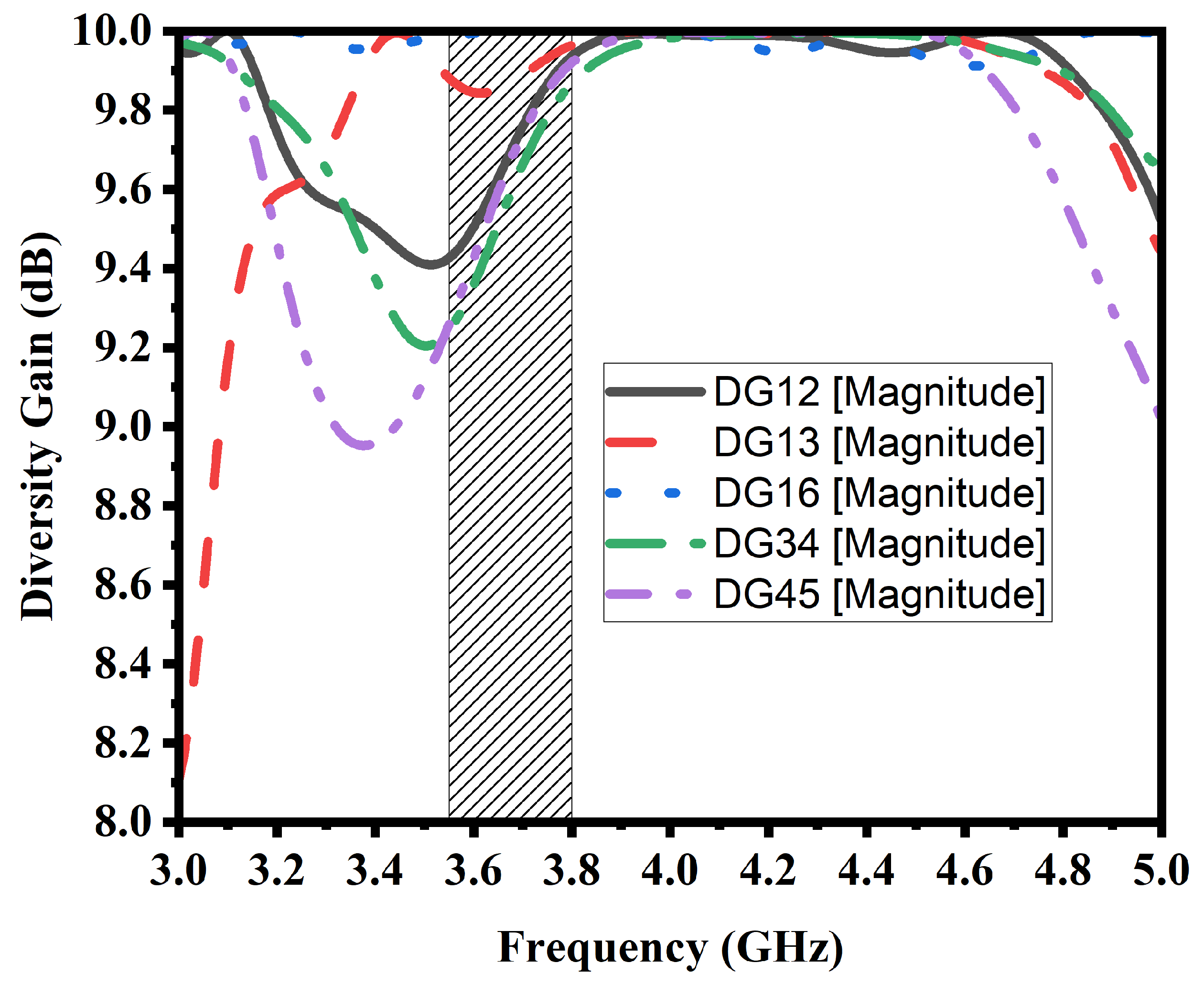
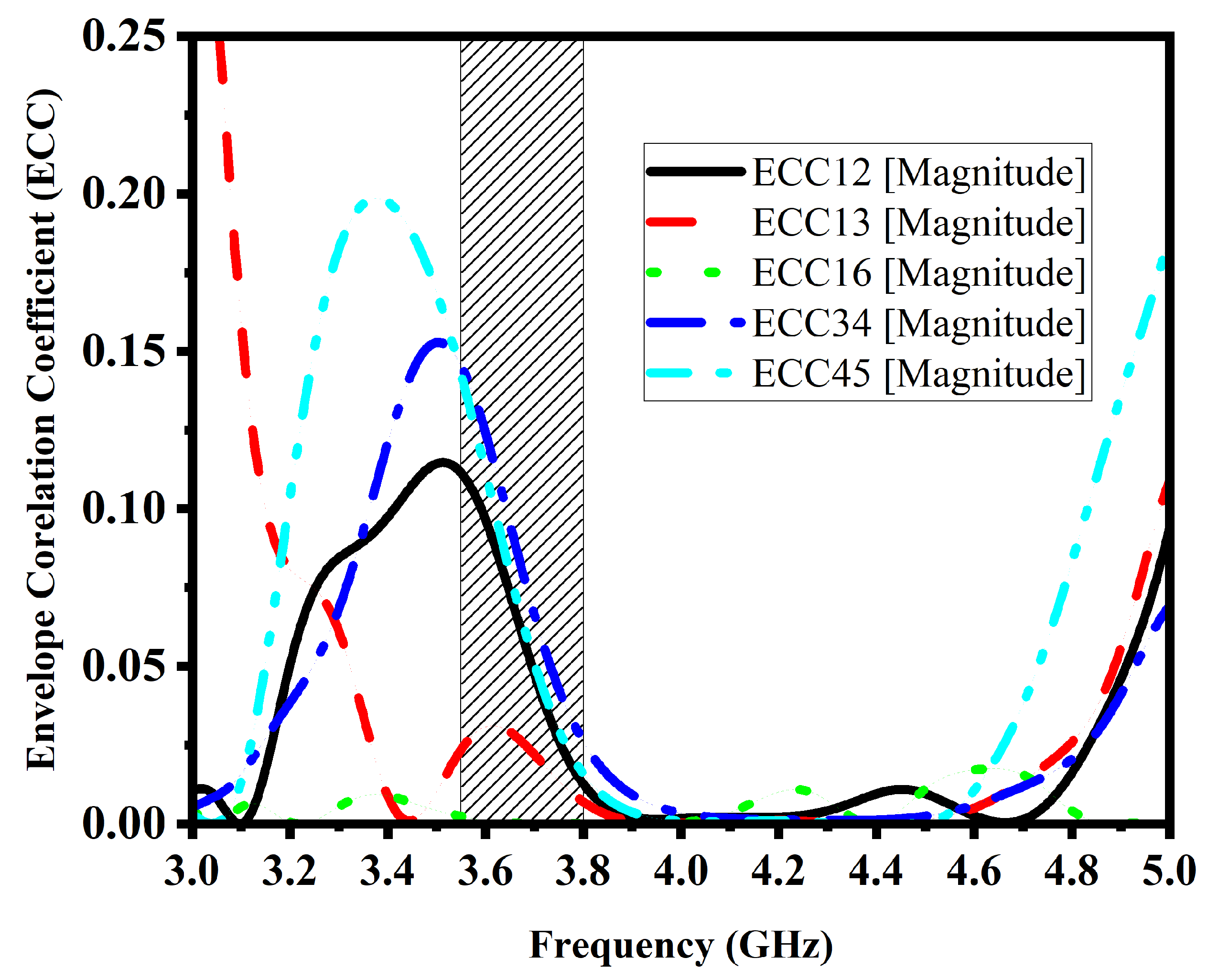
3.2. Diversity Gain and Envelop Correlation Coefficient

Investigating the diversity and multiplexing performances is crucial since, in addition to reflection, isolation, and radiation performances, diversity and multiplexing applications are the principal uses for the MIMO antenna. This section investigates the envelope correlation coefficients (ECCs) of various antenna pairs to assess and validate the diversity performance of the proposed MIMO antenna array [30]. The precise algorithm used to calculate the ECC has been made clear in [31]. Figure 6 demonstrates the proposed MIMO antenna’s simulated diversity gain.
Figure 7 shows the simulated ECC of the proposed antenna. The proposed MIMO antenna’s ECC was determined using the data from the S-parameters in CST post-processing templates. It can be seen in Figure 7 that the calculated ECC values in LTE bands 43, and 48/49 were less than 0.19, which is significantly better than the required ECC value of less than 0.25 in [31]. The proposed MIMO antenna array has desirable diversity capabilities since lower ECC values will result in higher diversity gain that approximates to 9.8 dB on average.

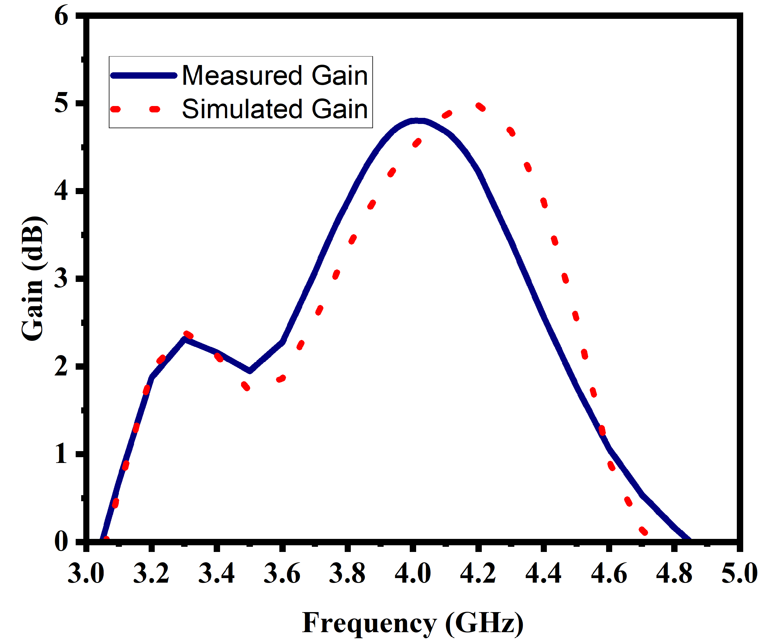
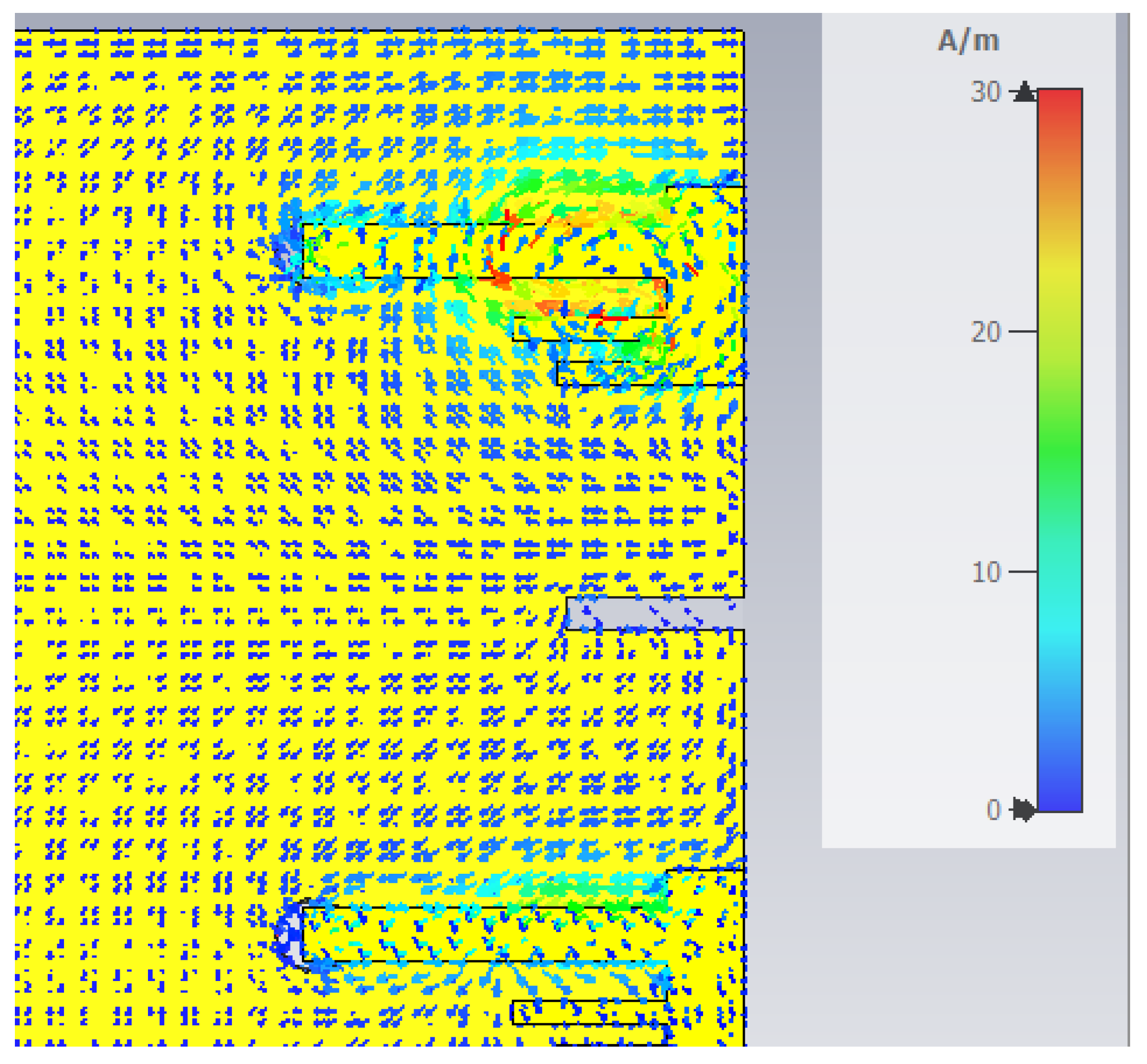
3.3. Gain of an Antenna and Current Distribution

Figure 8 shows the simulated and measured gain of Ant#5 in the proposed 5G MIMO antenna array. The minimum and maximum simulated gain of the proposed 5G MIMO antenna is 1.8 dBi and 5.09 dBi which cover the necessary LTE bands 43, and 48/49 bands, respectively. However, the maximum and minimum values of measured gains of 4.8 dBi and 1.9 dBi are suitable for the suggested design and cover the necessary bands. Figure 9 shows the current distribution of a proposed antenna. There is a maximum charge density due to the slot in the ground which is a necessary part to achieve the desired frequency band for LTE 43, and 48/49.

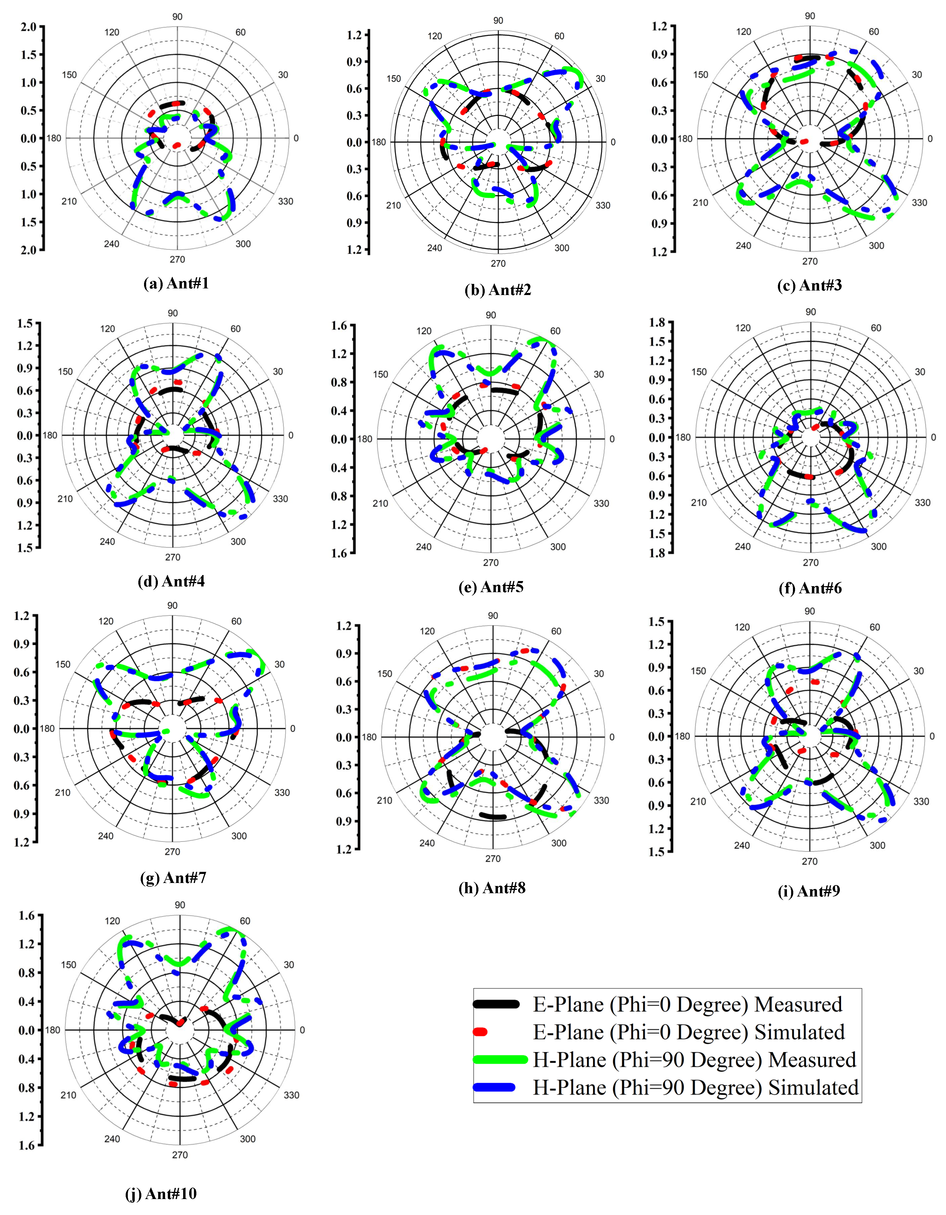
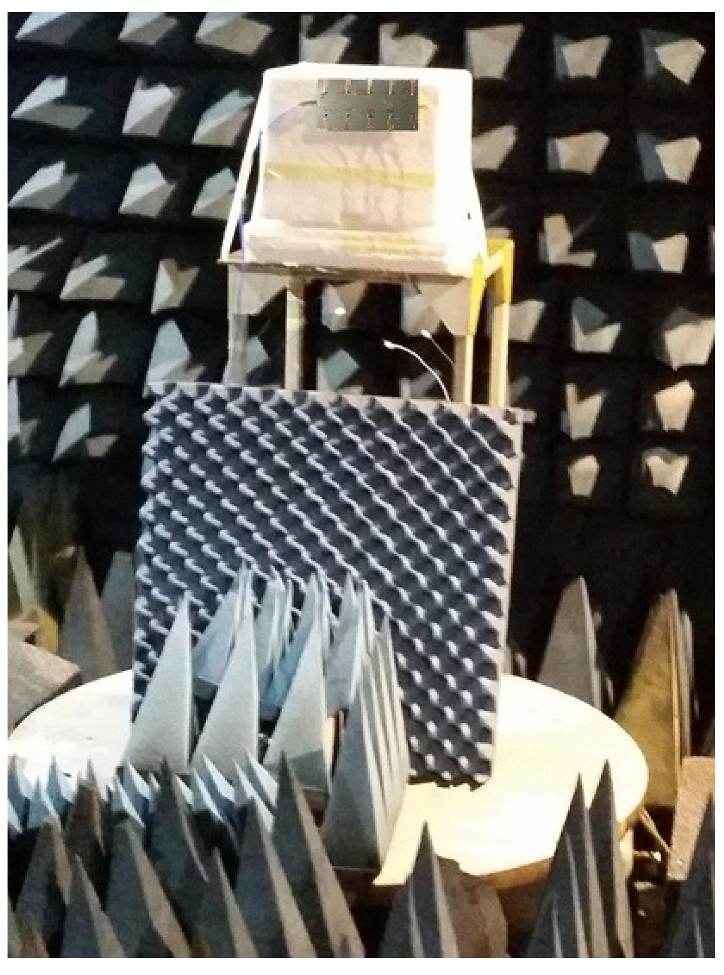
3.4. Radiation Pattern, Measurement Setup, and Comparison Table

The radiation pattern is the performance metric of an antenna that shows the power distribution in a 3D pattern. There are ten antennae on a proposed PCB prototype with a similar shape but each has a different pattern of each antenna, it is due to the current distribution effect of the adjacent antenna. Figure 10a–e, shows the E and H plane cuts off the 3D pattern of the first 5 antennas on the right side from Figure 2 in simulated and measured scenarios. Similarly, Figure 10f–j, shows the e and h plane cuts off the 3D pattern of the other five antennae on the left side from Figure 2 in both simulated and measured scenarios. Figure 10 shows that there is approximately no difference in the h plane, but the e plane is inverted of opposite antennas.
Figure 11 is taken from the anechoic chamber while measuring the antenna gain and radiation pattern. The antenna is mounted on the turn table to move the antenna at 360-degree elevation and 180-degree azimuth, and the wide-band horn antenna is used as a receiver. the proposed ten-port massive MIMO antenna array is compared with some renowned articles in Table 3. The fractional bandwidth is 12.97%, the ECC is 0.17 which is quite better for showing good isolation.

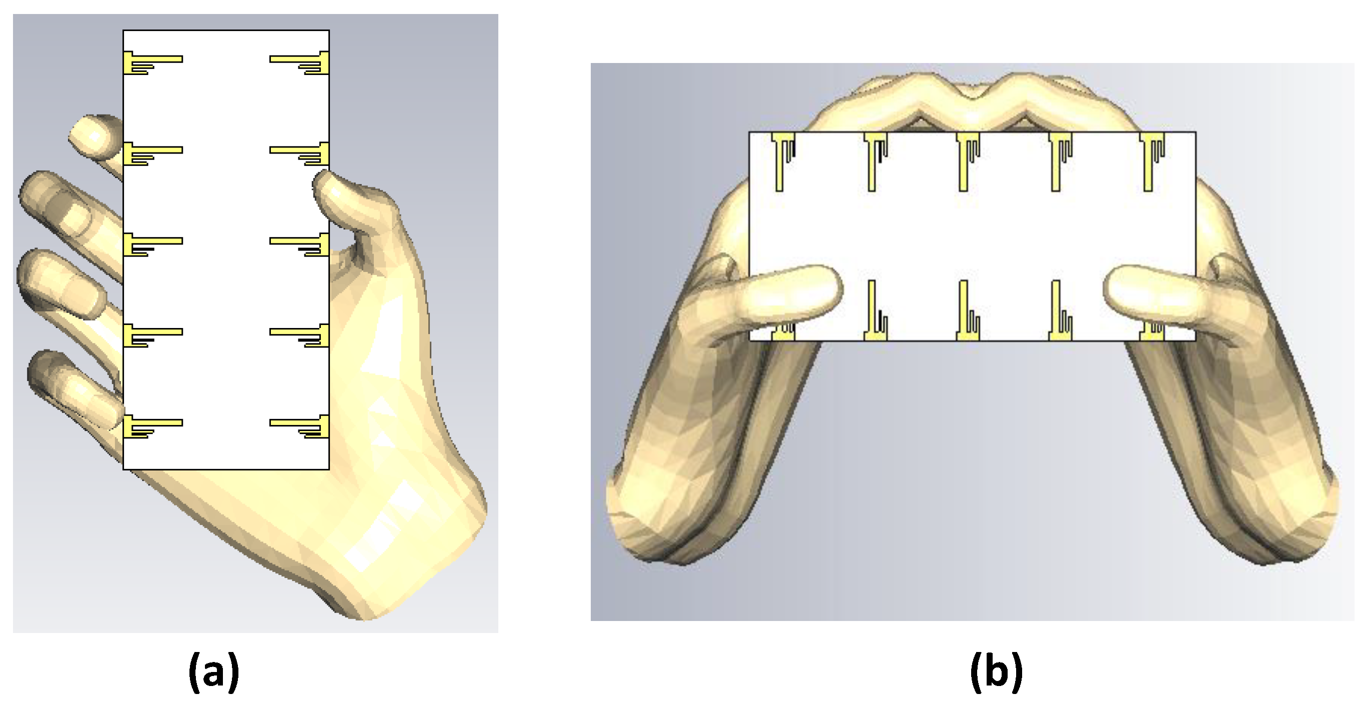
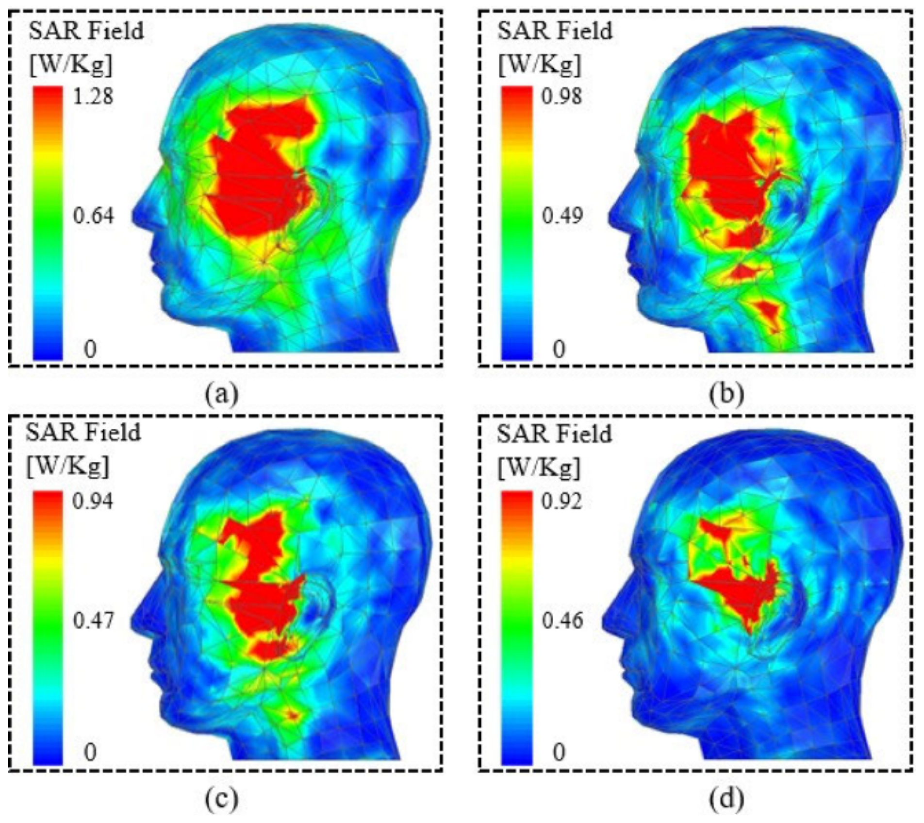
3.5. User Hand Analysis and SAR

The suggested solution is intended to cover desirable sub-6 GHz 5G bands for a smartphone terminal, as was previously mentioned. Therefore, it is necessary to look into how the user’s hand affects the device. As seen in Figure 12, the effects of single-handed chatting and two-handed gaming are examined here. First, a hand model that has the characteristics listed by [41] is imported from a CST library into the simulation file. It is widely known from the literature that a human hand has an effective permittivity range of 28 to 32 and an average electric conductivity range of 0.7 to 0.9 S/m. As a result, the hand model used in this investigation has a permittivity of 29 and an electric conductivity of 0.9 S/m.
The goal of this effort is to demonstrate a cheap, small, and effective mobile terminal. As a result, research is required to determine how such a system affects human health, particularly in uplink and downlink scenarios when it is in operational mode. The Specific Absorption Rate (SAR) is calculated to investigate this. SAR is typically calculated to assess how much a radiating system’s backward radiation affects the human body’s mass per unit of radiation intensity. The SAR should be less than 1.6 W/Kg for a 1-g tissue and 2 W/Kg for a 10-g tissue, in accordance with the guidelines. The apparatus was positioned 2 mm away from a representative human head in the simulated scenario in order to calculate the SAR. A CST library is used to import a human head with a well-known described characteristic. A total of 250 mW of input power was supplied to the antenna units, one unit of the antenna receiving a 25 mW input power. The SAR results of the antenna for 1-g tissue are displayed in Figure 13. The intended frequency bands showed a peak SAR value of 1.28 W/Kg. As a result, it can be said that the suggested antenna is secure for use around a human body.

4. Conclusions

The main target of this article is to design a 5G massive MIMO antenna array that can provide a high gain, high efficiency, and a minimum coefficient of correlation joining the antenna section. The suggested antenna array is anticipated to raise data rates, increase channel capacity, and improve signal quality in order to fulfill the needs of 5G wireless networks. The radiation pattern, gain, efficiency, and correlation coefficient are used to assess how well the planned antenna array performs. According to the simulation results, the suggested antenna array has a low correlation coefficient between the antenna elements, a peak diversity gain of 9.65 dBi, and a total efficiency of 67%. In conclusion, the suggested 10-element 5G massive MIMO antenna array is a potential option for mobile devices operating below 6 GHz, especially for LTE bands 43/48/49 applications. The system capacity and spectral efficiency of 5G wireless networks can both be greatly increased by the suggested antenna array. Additionally, to further highlight the value of such a design as a smart mobile terminal, the influence of a user’s hand for two distinct modes, namely gaming and chatting, is also shown. This study is also compared to other published studies in a brief overview of the literature. A prototype is made and measured to verify the idea and the calculated outcomes. It is discovered that there is very good agreement between the measured results and the simulated results for a number of critical performance characteristics. We think that this structure has a bright future in the upcoming generation of smartphones based on the performance and the measured findings.

Author Contributions

Conceptualization, M.Z.; Methodology, M.Z.; Software, A.K.; Formal analysis, H.M.; Investigation, M.Z. and H.S.; Writing—review & editing, S.S.; Supervision, Y.A. All authors have read and agreed to the published version of the manuscript.

Funding

This research is partially funded by Wrexham Glyndwr University.

Data Availability Statement

The data can be shared upon request.

Conflicts of Interest

The authors declare no conflict of interest.

References

  1. Elobied, A.A.; Yang, X.X.; Xie, N.; Gao, S. Dual-Band 2 × 2 MIMO Antenna with Compact Size and High Isolation Based on Half-Mode SIW. Int. J. Antennas Propag. 2020, 2020, 2965767. [Google Scholar] [CrossRef]
  2. Zhang, S.; Zhao, K.; Ying, Z.; He, S. Adaptive Quad-Element Multi-Wideband Antenna Array for User-Effective LTE MIMO Mobile Terminals. IEEE Trans. Antennas Propag. 2013, 61, 4275–4283. [Google Scholar] [CrossRef]
  3. Liu, X.; Zhang, J.; Xi, H.; Yang, X.; Sun, L.; Gan, L. A Compact Four-band High-isolation Quad-port MIMO Antenna for 5G and WLAN Applications. AEU-Int. J. Electron. Commun. 2022, 153, 154294. [Google Scholar] [CrossRef]
  4. Elfergani, I.T.E.; Hussaini, A.S.; Abd-Alhameed, R.A.; See2, C.H.; Child, M.B.; Rodriguez, J. Design of a compact tuned antenna system for mobile MIMO applications. In Proceedings of the 2012 Loughborough Antennas & Propagation Conference (LAPC), Loughborough, UK, 12–13 November 2012; pp. 1–4. [Google Scholar] [CrossRef]
  5. Dong, J.; Wang, S.; Mo, J. Design of a Twelve-Port MIMO Antenna System for Multi- Mode 4G/5G Smartphone Applications Based on Characteristic Mode Analysis. IEEE Access 2020, 8, 90751–90759. [Google Scholar] [CrossRef]
  6. Li, Z.; Du, Z.; Takahashi, M.; Saito, K.; Ito, K. Reducing mutual coupling of MIMO antennas with parasitic elements for mobile terminals. IEEE Trans. Antennas Propag. 2012, 60, 473–481. [Google Scholar] [CrossRef]
  7. Li, M.; Jiang, L.; Yeung, K.L. A general and systematic method to design neutralization lines for isolation enhancement in MIMO antenna arrays. IEEE Trans. Vehicular Technol. 2020, 69, 6242–6253. [Google Scholar] [CrossRef]
  8. Ikram, M.; Sharawi, M.S.; Shamim, A.; Sebak, A. A multiband dual standard MIMO antenna system based on monopoles (4G) and connected slots (5G) for future smart phones. Microw. Opt. Technol. Lett. 2018, 60, 1468–1476. [Google Scholar] [CrossRef]
  9. Sun, Q.; Sun, B.; Sun, L.; Huang, W.; Ren, Q. Broadband two-element array with hybrid decoupling structures for multimode mobile terminals. IEEE Antennas Wireless Propag. Lett. 2015, 14, 1431–1434. [Google Scholar] [CrossRef]
  10. Dong, J.; Yu, X.; Deng, L. A decoupled multiband dual-antenna system for WWAN/LTE smartphone applications. IEEE Antennas Wireless Propag. Lett. 2017, 16, 1528–1532. [Google Scholar] [CrossRef]
  11. Yu, K.; Li, Y.; Liu, X. Mutual coupling reduction of a MIMO antenna array using 3D novel meta material structures. Appl. Comput. Electromagn. Soc. J. 2018, 33, 758–763. [Google Scholar]
  12. Li, M.-Y.; Ban, Y.-L.; Xu, Z.-Q.; Guo, J.; Yu, Z.-F. Tri-polarized 12-antenna MIMO array for future 5G smartphone applications. IEEE Access 2018, 6, 6160–6170. [Google Scholar] [CrossRef]
  13. Zhu, F.-G.; Xu, J.-D.; Xu, Q. Reduction of mutual coupling between closely-packed antenna elements using defected ground structure. Electron. Lett. 2012, 45, 601–602. [Google Scholar] [CrossRef]
  14. Suntives, A.; Abhari, R. Miniaturization and isolation improvement of a multiple-patch antenna system using electromagnetic bandgap structures. Microw. Opt. Technol. Lett. 2013, 55, 1609–1612. [Google Scholar] [CrossRef]
  15. Adamiuk, G.; Beer, S.; Wiesbeck, W.; Zwick, T. Dual-orthogonal polarized antenna for UWB-IR technology. IEEE Antennas Wireless Propag. Lett. 2009, 8, 981–984. [Google Scholar] [CrossRef]
  16. Iqbal, A.; Saraereh, O.A.; Ahmad, A.W.; Bashir, S. Mutual coupling reduction using F-shaped stubs in UWB-MIMO antenna. IEEE Access 2017, 6, 2755–22759. [Google Scholar] [CrossRef]
  17. Pandit, S.; Mohan, A.; Ray, P. A compact planar MIMO monopole antenna with reduced mutual coupling for WLAN applications using ELC resonator. In Proceedings of the 2016 Asia-Pacific Microwave Conference (APMC), New Delhi, India, 5–9 December 2016; pp. 1–4. [Google Scholar]
  18. Verma, A.K.; Nakkeeran, R.; Vardhan, R.K. Design of 2 × 2 single-sided wrench-shaped UWB MIMO antenna with high isolation. In Proceedings of the 2016 International Conference on Circuit, Power and Computing Technologies (ICCPCT), Nagercoil, India, 18–19 March 2016; pp. 1–3. [Google Scholar]
  19. Cui, L.; Guo, J.; Liu, Y.; Sim, C. An 8-element dual-band MIMO antenna with decoupling stub for 5G smartphone applications. IEEE Antennas Wirel. Propag. Lett. 2019, 18, 2095–2099. [Google Scholar] [CrossRef]
  20. Li, Y.; Sim, C.; Luo, Y.; Yang, G. High isolation 3.5 GHz eight antenna MIMO array using balanced open-slot antenna element for 5G smartphones. IEEE Trans. Antenna Propag. 2019, 67, 3820–3830. [Google Scholar] [CrossRef]
  21. Malathi, A.C.; Thiripurasundari, D. Compact 2 × 1 MIMO Antenna System for LTE Band. Prog. Electromagn. Res. C 2017, 75, 63–73. [Google Scholar] [CrossRef]
  22. Alexa, F.; Bardeanu, B.; Vatau, D. MIMO antenna system for LTE. In Proceedings of the 2013 36th International Conference on Telecommunications and Signal Processing (TSP), Rome, Italy, 2–4 July 2013; pp. 294–298. [Google Scholar] [CrossRef]
  23. Qualcomm. Making the Best Use of Licensed and Unlicensed Spectrum. September 2015. Available online: https://www.qualcomm.com/media/documents/files/making-the-best-use-of-unlicensed-spectrumpresentation.pdf (accessed on 20 June 2023).
  24. IMT-2020 (5G) Promotion Group. White Paper on 5G Concept. February. 2015. Available online: http://www.imt-2020.org.cn/zh/documents/download/4 (accessed on 20 June 2023).
  25. SK Telecom. SK Telecom 5G White Paper. October 2014. Available online: http://www.sktelecom.com/img/pds/press/SKT-5G%20White%20Paper_V1.0_Eng.pdf (accessed on 20 June 2023).
  26. Arunraj, M.; Mathivadhani, A.; Deepa, D.; Kumar, S.A. Design of F shaped MIMO antenna for WIMAX Applications. In Proceedings of the 2019 Third International Conference on Inventive Systems and Control (ICISC), Coimbatore, India, 10–11 January 2019; pp. 159–161. [Google Scholar] [CrossRef]
  27. Yuan, X.-T.; Chen, Z.; Gu, T.; Yuan, T. A Wideband PIFA-Pair-Based MIMO Antenna for 5G Smartphones. IEEE Antennas Wirel. Propag. Lett. 2021, 20, 371–375. [Google Scholar] [CrossRef]
  28. Kumar, D.R.; Babu, G.V.; Narayan, K.S. Compact F-Shaped Antenna with its Analytical Modelling Resonating at 3.5 GHz for 5G Applications. In Proceedings of the 2021 IEEE Indian Conference on Antennas and Propagation (InCAP), Jaipur, India, 13–16 December 2021; pp. 1–4. [Google Scholar] [CrossRef]
  29. Parchin, N.O.; Al-Yasir, Y.I.; Basherlou, H.J.; Abdulkhaleq, A.M.; Sajedin, M.; Abd-Alhameed, R.A.; Noras, J.M. Modified PIFA Array Design with Improved Bandwidth and Isolation for 5G Mobile Handsets. In Proceedings of the 2019 IEEE 2nd 5G World Forum (5GWF), Dresden, Germany, 30 September–2 October 2019; pp. 199–203. [Google Scholar] [CrossRef]
  30. Sharawi, M.S. Printed Multi-Band MIMO Antenna Systems and Their Performance Metrics [Wireless Corner]. IEEE Antennas Propag. Mag. 2013, 55, 218–232. [Google Scholar] [CrossRef]
  31. Li, Y.; Sim, C.-Y.-D.; Luo, Y.; Yang, G. 12-Port 5G Massive MIMO Antenna Array in Sub-6GHz Mobile Handset for LTE Bands 42/43/46 Applications. IEEE Access 2018, 6, 344–354. [Google Scholar] [CrossRef]
  32. Zou, H.; Li, Y.; Sim, C.-Y.-D.; Yang, G. Design of 8 × 8 dual-band MIMO antenna array for 5G smartphone applications. Int. J. RF Microw. Comput.-Aided Eng. 2018, 28, e21420. [Google Scholar] [CrossRef]
  33. Guo, J.L.; Cui, L.; Li, C.; Sun, B.H. Side-edge frame printed eight-port dual-band antenna array for 5G smartphone applications. IEEE Trans. Antennas Propag. 2018, 66, 7412–7417. [Google Scholar] [CrossRef]
  34. Li, Y.; Sim, C.-Y.-D.; Luo, Y.; Yang, G. Metal-frame-integrated eight-element multiple-input multiple-output antenna array in the long term evolution bands 41/42/43 for fifth generation smartphones. Int. J. RF Microw. Comput.-Aided Eng. 2019, 29, e21495. [Google Scholar] [CrossRef]
  35. Wang, H.; Zhang, R.; Luo, Y.; Yang, G. Compact eight-element antenna array for triple-band MIMO operation in 5G mobile terminals. IEEE Access 2020, 8, 19433–19449. [Google Scholar] [CrossRef]
  36. Jaglan, N.; Gupta, S.D.; Sharawi, M.S. 18 elements massive MIMO/diversity 5G smartphones antenna design for sub-6 GHz LTE bands 42/43 applications. IEEE Open J. Antennas Propag. 2021, 2, 533–545. [Google Scholar] [CrossRef]
  37. Huang, J.; Dong, G.; Cai, J.; Li, H.; Liu, G. A quad-port dual band MIMO antenna array for 5G smartphone applications. Electronics 2021, 10, 542. [Google Scholar] [CrossRef]
  38. Huang, J.; Dong, G.; Cai, Q.; Chen, Z.; Li, L.; Liu, G. Dual-band MIMO antenna for 5G/WLAN mobile terminals. Micromachines 2021, 12, 489. [Google Scholar] [CrossRef]
  39. Serghiou, D.; Khalily, M.; Singh, V.; Araghi, A.; Tafazolli, R. Sub-6 GHz dual-band 8 × 8 MIMO antenna for 5G smartphones. IEEE Antennas Wireless Propag. Lett. 2020, 19, 1546–1550. [Google Scholar] [CrossRef]
  40. Ahmed, M.; Zafar, Z.; Javed, I.; Zahid, M.; Amin, Y. 12 Element Inverted E-Shaped Massive MIMO Antennas for Future 5G Smartphone Applications. In Proceedings of the 2023 7th International Multi-Topic ICT Conference (IMTIC), Jamshoro, Pakistan, 10–12 May 2023; pp. 1–5. [Google Scholar] [CrossRef]
  41. Kiani, S.H.; Iqbal, A.; Wong, S.-W.; Savci, H.S.; Alibakhshikenari, M.; Dalarsson, M. Multiple Elements MIMO Antenna System with Broadband Operation for 5th Generation Smart Phones. IEEE Access 2022, 10, 38446–38457. [Google Scholar] [CrossRef]
Figure 1. Dimensions and geometry of a 10 port array (a) front view of the proposed MIMO antenna design (b) dimensions of antenna element (c) rare view of the proposed MIMO antenna configuration (d) dimensions of the ground slots.
Electronics 12 04005 g001
Figure 2. Fabricated prototype (a) Back view. (b) Front view.
Electronics 12 04005 g002
Figure 3. Simulated and measured reflection coefficient S 1 , 1 of antenna 1.
Electronics 12 04005 g003
Figure 4. Simulated reflection coefficients of Ant#1 to Ant#5 (Shaded region for LTE 43, 48/49).
Electronics 12 04005 g004
Figure 5. Simulated transmission coefficients (coupling) between different antenna pairs (Shaded region for LTE 43, 48/49).
Electronics 12 04005 g005
Figure 6. Simulated Diversity Gain of the proposed antenna (Shaded region for LTE 43, 48/49).
Electronics 12 04005 g006
Figure 7. Calculated values for the envelope correlation coefficient (ECC) based on simulated s-parameters in the shaded LTE bands 43, and 48/49.
Electronics 12 04005 g007
Figure 8. Simulated and Measured Gain of Ant#5.
Electronics 12 04005 g008
Figure 9. Current distribution of a proposed antenna at resonance of 3.7 GHz.
Electronics 12 04005 g009
Figure 10. Simulated and measured radiation pattern of 10 port MIMO antenna array.
Electronics 12 04005 g010
Figure 11. Measurement Setup of a Proposed Antenna.
Electronics 12 04005 g011
Figure 12. User Hands (a) Single Hand Mode (SHM). (b) Two Hand Mode (THM).
Electronics 12 04005 g012
Figure 13. SAR of Ant#1 in a prototype. (a) 3.55 GHz (b) 3.6 GHz (c) 3.7 GHz (d) 3.8 GHz.
Electronics 12 04005 g013
Table 1. Comparison of a single Inverted F-shaped Antennas in MIMO.
Ref. No.Dimension (mm 2 )Resonance Freq. (GHz)Bandwidth (MHz)Gain (dBi)
[26]31 × 283.513504.5
[27]15 × 6.24.52000not mentioned
[28]19.3 × 6.23.5250not mentioned
[29]26 × 123.55600not mentioned
Proposed20 × 93.74805.1
Table 2. Parameters of a Proposed Antenna.
ParameterValue (mm)ParameterValue (mm)ParameterValue (mm)
S l 150S w 70gap22
fl16.5fw2.43pw 1 3.5
pw 2 7pw 3 5pl 1 9
pl 2 1.785pl 3 1pl 4 1
pl 5 1gap113gap214.8
gap39.15gap415.15gcw19.99
gcw28gcl11.5gcl 2 1.7
Table 3. Performance comparison of various state-of-the-art 5G antennas.
Ref.Bandwidth (GHz)Isolation (-dB)ECCTotal Eff. (%)Radiator Size in ( λ 3 )
Proposed3.46–3.94 (−10dB)>11<0.19>670.17 × 0.05 × 0.01
 [19]3.3–4.2, 4.8–5.0 (−6 dB)>10<0.1253.8–79.10.21 × 0.07 × 0.01
 [31]3.4–3.8, 5.15–5.92 (−6 dB)>12<0.1541–790.13 × 0.04 × 0.01
 [32]3.4–3.6, 5.15–5.92 (−6 dB)>12<0.1>500.17 × 0.05 × 0.01
 [33]3.4–3.6, 4.8–5.1 (−6 dB)>12<0.140–850.17 × 0.03 × 0.01
 [34]2.49–2.69, 3.4–3.8 (−6 dB)>10.5<0.244–660.02 × 0.17 × 0.01
 [35]3.35–3.82, 4.79–6.2 (−6 dB)>10.5<0.12>430.17 × 0.03 × 0.01
 [36]3.3–3.8 (−10 dB)>20<0.01>870.11 × 0.04 × 0.02
 [37]3.4–3.6, 4.8–5.0 (−10 dB)>16.5<0.0182–850.16 × 0.07 × 0.01
 [38]3.3–3.8, 4.8–5.9 (−10 dB)>15<0.02>700.16 × 0.07 × 0.01
 [39]3.1–3.85, 4.8–6.0 (−10 dB)>17<0.0665–710.20 × 0.05 × 0.01
 [40]2–2.4, 5.8–6.1 (−6 dB)>48<0.1270–840.24 × 0.108 × 0.01
Disclaimer/Publisher’s Note: The statements, opinions and data contained in all publications are solely those of the individual author(s) and contributor(s) and not of MDPI and/or the editor(s). MDPI and/or the editor(s) disclaim responsibility for any injury to people or property resulting from any ideas, methods, instructions or products referred to in the content.

