1. Introduction
Due to the broadcasting and superposition characteristics of electromagnetic waves, wireless communication is very susceptible to the threat of malicious jamming. Traditional communication anti-jamming mainly utilizes direction-sequence spread spectrum (DSSS) and frequency hopping (FH). These methods not only consume additional spectrum resources, but also are easily targeted by intelligent jammers. Recently, with the development of meta-materials, a revolutionary technique called reconfigurable intelligent surface (RIS) has been proposed, which has received extensive attention due to its potential to reconfigure the electromagnetic wave propagation environment in a cost and energy-efficient fashion [
1].
Building upon the aforementioned advantages, RIS has been widely adopted to enable anti-jamming communication by jointly optimizing the beamforming of the base station (BS) and the phase shifts of RIS, enhancing the desired signals while eliminating the jamming signals [
2,
3,
4]. An anti-jamming method was proposed in [
2], in which the transmitting beam and RIS phase shift were joint optimized. Furthermore, the performance of RIS-assisted wireless communication under the conditions of simultaneous jamming and eavesdropping attacks was studied in [
5,
6]. However, the above papers assume that the BS accurately knows about prior information such as jamming power or jamming channel, which often fail in practical situations. In [
5,
7], the optimization and regulation methods of RIS parameters were studied under the conditions of jamming perception error and uncertainty in the direction of jamming. In [
8], the impact of the correlation between interference and communication signals on the performance of communication systems was studied. The results showed that when the spatial correlation matrix between the interference channel and the communication channel is gradually orthogonal, the signal-to-noise ratio (SNR) at the receiver is proportional to the quadratic number of RIS units; otherwise, the SNR at User is linearly related to the number of RIS units. In [
9,
10,
11], a method for channel estimation and RIS beamforming based on codebooks was studied. In imperfect channels, beam optimization of RIS can be achieved by training codebooks.
The above research utilized only one RIS to improve the performance of the wireless communication. Compared with single RIS-assisted communication, dual RIS can increase the number of wireless links from the BS to the User, and the correlation between these wireless links is relatively small. This enables dual RIS-assisted communication to flexibly design beamforming vectors and improve performance [
12,
13,
14,
15,
16]. In fact, multi RIS-assisted communication has been studied in [
17,
18,
19], and the results show that under the premise of a certain transmission power, the symbol error rate of multi RIS-assisted communication is significantly lower than that of a system that is not RIS-assisted and decreases with the increase in the number of RIS and the number of units per RIS. In [
20], distributed RIS-assisted wireless communication was studied by embedding a switch controller in RIS to optimize resource allocation, and the results showed that this scheme has good energy efficiency. In addition, multi-layer RIS was also studied in [
21]. Compared to single-layer RIS, multi-layer RIS utilizes more complex structures to achieve better communication performance.
However, the existing research mainly focused on passive RIS, which suffer from a severe “double fading” effect, and compared to direct links, the performance gain is negligible. To overcome this deficiency, the concept of active RIS was proposed in [
22,
23,
24,
25,
26]. The key feature of active RIS is that each RIS unit is equipped with a power amplifier that not only adjusts the signals’ phase shifts, but also amplifies the amplitude by consuming some power. The results show that, compared with the passive RIS-assisted communication, the active RIS can achieve more than 120% capacity gain, thus overcoming the “double fading” effect [
23]. However, the application of active RIS in anti-jamming communication has not been thoroughly studied, and research in this area is urgently needed.
This paper proposes an anti-jamming communication model assisted by multiple active RISs and a channel space anti-jamming algorithm based on BCD. The main contributions of this paper are summarized as follows:
An anti-jamming communication model assisted by multiple active RISs is proposed, in which the RISs can be dynamically turned on or off depending on the requirements. This model constructs dynamic redundant channels not only to improve anti-jamming communication ability, but also to overcome the inherent drawbacks of “double fading” in passive RIS. At the same time, it can also improve system energy efficiency by turning off RIS through a switch controller.
The performance of active RIS-assisted anti-jamming communication is analyzed through theoretical derivation and compared with passive RIS to reveal the superiority of active RIS. The numerical results show that in small-scale deployment, the performance of active RIS-assisted anti-jamming communication is better than that of passive RIS.
To solve the problem of maximum communication rate, a controllable multi-active RIS assisted anti-jamming algorithm based on BCD is proposed. Firstly, the uncertain jamming information is robustly processed. Secondly, the CCD and SCA are used to optimize the phase and amplitude of the active RIS, respectively. Then, the closed-form solution of the transmitting and receiving beams is derived. Finally, greedy algorithms are used to switch multiple RIS. Compared with semidefinite relaxation (SDR), the proposed algorithm has lower complexity and a better performance.
The main symbols of this article are as follows: The lowercase, bold lowercase, and bold uppercase, such as x, and represent scalars, vectors, and matrices, respectively. represents the absolute value of x, , , , , and represent the absolute, the norm, the conjugate transposition, conjugation and generalized inverse of the vector element , respectively. represents the element in the -th row and -th column. represents the real part of a complex number or matrix. represents a circularly symmetric complex Gaussian (CSCG) distribution with a mean of and a variance of .
2. System Model
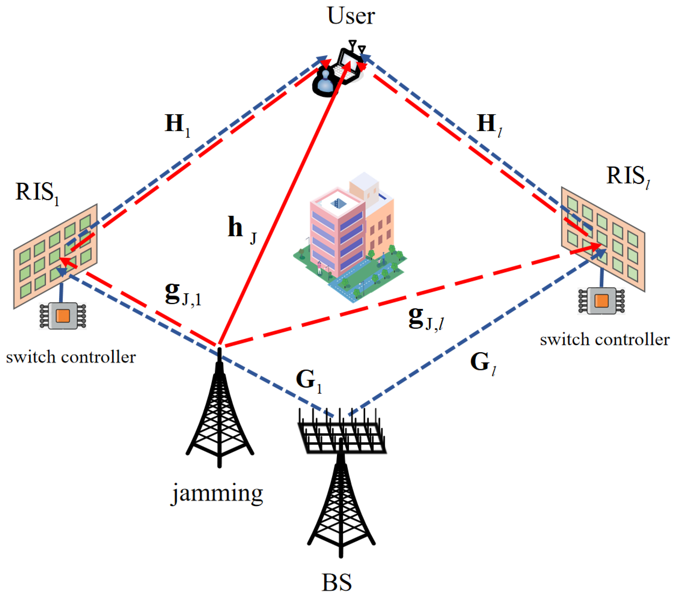
We considered a multi-input multi-output (MIMO) system with
L active RIS as shown in
Figure 1, where the BS and User are equipped with
and
antennas, respectively, and the
-th (
) active
is connected to a switch controller and contains
reflection units. The BS can control the working status of
through a switch controller, represented as
, where “0” and “1” represents
that is off and on, respectively.
Assuming that the direct link between the BS and User is blocked and the channel coefficients of BS-
, jammer-
,
-User, jammer–User are
,
,
,
, respectively. The phase shift matrix and amplitude matrix of active
are
and
, respectively, where
and
represent the reflection phase and reflection amplitude of the
i-th unit of
. The BS beam and User beam are
and
, respectively. Due to the long deployment distance of each RIS and the reflection beam of the RIS pointing towards the BS or User, ignoring the secondary reflection between different active RISs, the signal received from the User can be expressed as
where
and
are the signals of the BS and jammer, respectively. In addition,
and
are the thermal noise of the active
and the noise of the User, respectively, where
,
are the average power of the noise.
From (1), it can be seen that the received signal to jamming plus noise ratio (SJNR) of the User is
Due to the non-cooperative relationship between the jammer and the BS, we assume that the involved channel state information (CSI) of jamming channels, i.e.,
and
, cannot be accurately obtained by the BS. Therefore, determining how to optimize and regulate multi active RIS under the condition of jamming information uncertainty has become the key issue. To solve this problem, we model uncertain jamming information as the uncertainty of channels
and
, namely [
6]:
where
and
are the direction and elevation angles of the channel, and
,
are the upper and lower limits of the corresponding angles, indicating that the jamming has not been precisely identified but is a random variable located within the range. Thus, the anti-jamming problem based on multi active RIS is transformed into the joint optimization of the transmitting beam
, receiving beam
, active
phase-shifting matrix
, and amplitude matrix
, as well as RIS switch status
, to maximize the communication rate under the condition of the uncertain area of jamming information
and the constraints of maximum transmitting power
, maximum active
amplitude
and power
, and receiving beam
, etc., namely:
where C1 is the BS’s power constraint, C2 is the RIS phase shift matrix constraint, C3 is the active RIS amplitude matrix constraint, C4 is the active RIS power constraint, in which
is the maximum power of
, C5 is the User’s antenna beam constraint, and C6 is
state constraint. Objectively, (6) is a non-convex optimization problem that is difficult to solve due to the fact that both numerators and denominators in
are quadratic terms.
3. Performance Analysis
In this section, the performance of active RIS-assisted anti-jamming communication is analyzed and compared with passive RIS to reveal the advantages of active RIS. For the convenience of analysis, this section considers a single input–single output (SISO) system assisted by a single RIS, i.e., , .
3.1. Asymptotic SJNR of Active RIS
We assume that the amplification factor of each active RIS unit is the same, and for comparison with passive RIS, we consider Rayleigh-fading channels similar to [
1,
23]. At this point, we have
Due to the channel model being based on Rayleigh fading channels, we have
,
and
, where
is the corresponding channel fading coefficient.
Obviously, it is difficult to find the optimal solution for (5), as the jamming channel information is difficult to obtain and (5) is a non convex optimization problem. Therefore, we consider the suboptimal solution of active RIS optimization to maximize the denominator of (5); that is, to maximize the transmitted signal. When N is large enough, by invoicing the Lindeberg–Levy central limit theorem, we obtain . Similarly, it can be concluded that , , and . In order to maximize the power utilization of active RIS, it can be concluded from the constraint of (5) that .
By substituting the above transformation into (5), it can be concluded that
From (6), it can be seen that the asymptotic SJNR of active RIS-assisted anti-jamming is proportional to the number of RIS units N and depends on BS power and active RIS power . When , . This indicates that when the BS transmission power is high enough, the impact of BS-RIS channel fading, jamming signals and active RIS thermal noise can be ignored. The asymptotic SJNR of the active RIS only depends on the channel fading of the RIS-User and the noise generated by the User. Similarly, when , . This indicates that when the power of the active RIS is large enough, the asymptotic SJNR upper bound of the active RIS anti-jamming depends on the BS-RIS channel fading, Jammer-RIS channel fading, and RIS thermal noise. At this time, the jamming power and transmission power have a significant impact on the anti-jamming performance.
3.2. Active RIS VS. Passive RIS
Similar to (6), we can obtain the asymptotic SJNR of passive RIS-assisted anti-jamming communication as follows:
According to (7), for passive RIS-assisted anti-jamming communication, the strength of the User’s transmitted signal is proportional to
, while the jamming signal is only proportional to
N, and the noise is independent of the number of RIS units. Comparing (6) with (7), it can be seen that the passive RIS outperforms active RIS, if
In other words, when the number of RIS units is small, the anti-jamming performance of active RIS is better than that of passive RIS. And the critical value N is a function of the RIS-User channel fading , Jammer-RIS channel fading , and the jammer power .
3.3. Simulation Results and Numerical Analysis
In this subsection, we consider a specific scenario to compare the performance between active RIS and passive RIS. Assuming , , and . For fair comparison, we set . The performance of passive RIS exceeds that of active RIS when the number of RIS units is larger than 4988, which requires large-scale deployment of passive RIS and is difficult to achieve.
Figure 2 shows the relationship between the asymptotic SJNR and the number of RIS units
N. When
, the SJNR of an active RIS is 14 dB higher than that of passive RIS. Only when
N approaches 5000 can passive RIS perform better than active RIS. This is consistent with our analysis.
Through the above comparison, it can be found that although active RIS introduces thermal noise and amplifies jamming signals, it can still achieve higher SJNR than passive RIS. This is because the BS’s signal reflected by the active RIS can be coherently superimposed to the User, while the jamming signal and thermal noise cannot. Compared with the “double fading” of passive RIS, active RIS can compensate for the “double fading” effect to some extent by amplifying the transmitted signal. Therefore, when the number of RIS units is small, the auxiliary performance of active RIS-assisted anti-jamming communication is better than that of passive RIS.
4. Problem Optimization
In this section, we propose a low-complexity algorithm to solve the objective function (4). Firstly, the robust jamming channel is obtained via discretization the uncertainty region of jamming information in
Section 4.1. Secondly, the closed-form solution of the BS and User beams is given in
Section 4.2. Thirdly, the CCD algorithm is used to obtain the solution to the active RIS phase shift matrix in
Section 4.3. Next, the active RIS amplitude optimization matrix is obtained using SCA in
Section 4.4. Then, the greedy algorithm is used to obtain the switching matrix of active RIS in
Section 4.5. Finally, the BCD algorithm is used to alternately optimize the above variables and obtain the final solution in
Section 4.6.
Then, the alternative optimization method is used to decouple multiple optimization variables and optimize them, respectively. Finally, the greedy algorithm is used to optimize the RIS switching variables.
4.1. Robust Processing for Uncertain Jamming Information
In order to solve the problem of jamming channel uncertainty, we uniformly discretize the azimuth and elevation of matrix elements in (3); that is,
where
,
represent the azimuth and elevation of channel
,
, respectively. And
,
represent the amount of discretization of the jamming channel azimuth and elevation error range, respectively. We assume that the jamming is uniformly distributed in
, thereby obtaining the robustly processed jamming channel
and
. By incorporating the robust jamming into the objective function (4), the minimization problem of
can be solved.
4.2. Optimization of Transmitting and Receiving Beams
Due to the fact that the system proposed in this paper is a single receiver with multiple antenna, the beam based on the maximum ratio transmission (MRT) [
27] principle is the optimal transmission beam of the objective function (4). In addition, since the transmitting beam power of the BS is directly proportional to SJNR, it can be concluded that the optimal beam for the BS is
In order to minimize the thermal noise of active RIS, the receiving beam using the minimum mean square error (MMSE) criterion is selected as the optimal solution. It can be expressed as:
where
,
,
, respectively.
4.3. Optimization of RIS Phase Shift Matrix
In this subsection, we use the CCD algorithm to optimize the phase shift matrix
of
. Define intermediate variables
,
,
, and
, respectively. Due to the monotonic nature of logarithmic functions, the objective function (4) can be written as
where
,
,
,
, respectively. Equation (
12) is a non-convex quadratic fraction, so
is difficult to solve directly. Therefore, we use the Dinkelbach method to transform the objective function of (12) into the following equivalent form:
where
is a positive Dinkelbach parameter,
,
,
,
, and
, respectively. After removing the constant term in (13), the RIS phase shift matrix optimization subproblem can be obtained.
We use the CCD algorithm to solve (14), which consists of the Dinkelbach parameter
and the optimization vector
, to form a new optimization vector
with a length of
, where
is the sum of the number of multiple RIS units. Then, using the alternating optimization method, the
variables are sequentially optimized until the algorithm converges. Specifically, we expand the objective function in (14) as:
where
. At this point, we can obtain sub-problems for
variables and update them using the CCD algorithm:
where
is a complex set with modulus 1, and
is the part of Equation (
15) that removes the constant term, i.e.,
. Therefore, the optimization variables
in Equation (
16) can be solved using the following equation:
According to the properties of the conjugate function, the closed-form solution of Equation (
17) can be obtained:
By alternately updating and , the optimal closed-form solution of the multi-RIS phase shift matrix can be obtained.
4.4. Optimization of RIS Amplitude Matrix
In this subsection, we use the SCA to optimize the amplitude matrix
of
. Define the intermediate variable
,
,
, and
, respectively. Equation (4) can be rewritten as
To solve the non-convex problem (19), we introduce several auxiliary variables to transform the problem into a solvable form. Let
where the auxiliary variable
represents the jamming and noise power received by the User. It should be noted that the reformulated problem (20) is equivalent to the original problem (16), if the equalities in C7 and C8 hold.
Next, we propose a SCA method, which approximates the square root by using a convex upper-bound in each iteration. For convenience, we define
and
as the iterative optimization variables at the
-th-step iteration. Then, we exploit the first-order Taylor polynomial of
around the point
to approximate the original constraint, and thus we have a convex upper-bound, i.e.,
The problem (20) can be transformed into a convex optimization problem through (21) transformation. By randomly generating initial values of the active RIS amplitude matrix calculating and iteratively updating them until converges, the amplitude matrix of can be obtained.
4.5. Optimization of RIS Switch Status
After solving the RIS phase shift matrix , amplitude matrix , transmit beam , and receive beam , the objective function (4) is transformed into a nonlinear integer optimization problem with multiple RIS switch states as variables. This subsection presents a greedy multi-RIS switch state control algorithm, as shown in Algorithm 1. The basic idea is to first turn on all RIS, then turn them off one by one, and compare the objective functions before and after turning them off to determine whether turning on the RIS is beneficial for anti-jamming, until all RIS are traversed.
At step 1 of Algorithm 1, initialize the switch matrix of RIS to turn all RIS on. At step 2, calculate the initial value
of the objective value (2). At step 5, calculate the target value
by turning off
one by one. And find the maximum objective value
in step 7 and update the initial value
in step 9 until the algorithm converges, which means that turning off
can improve the anti-jamming performance until turning off any
cannot improve the anti-jamming performance. At this point, terminating the loop can obtain the RIS switch matrix
.
| Algorithm 1 Greedy method for RIS switch optimization |
- 1:
Initialize - 2:
Calculate the objective value (2), which is denoted by - 3:
while
do - 4:
if then - 5:
Let , Calculate the objective value (2), which is denoted by - 6:
end if - 7:
Calculate - 8:
if then - 9:
Let , - 10:
else - 11:
break - 12:
end if - 13:
end while - 14:
Output
|
4.6. Multi-Active RIS-Assisted Anti-Jamming Based on BCD Algorithm
The overall process of the proposed algorithm in this paper is shown in Algorithm 2. First, initialize the RIS phase shift matrix
, amplitude matrix
, transmitter beam
, and receiver beam
. And define the tolerable error
, the number of algorithm cycles
N to ensure the robustness of the algorithm. And in step 2, calculate
through (2). Continuously update the optimization variable
in steps 3 to step 11 until it converges or reaches the number of cycles. And output
in step 12.
| Algorithm 2 Multi-active RIS-assisted anti-jamming based on BCD algorithm |
- 1:
Initialize and define error values and number of cycles N - 2:
Calculate the objective value (2), which is denoted by - 3:
for
do - 4:
Calculate (10), (11) and (16) to obtain , , . Calculate (20) using CVX to obtain and run Algorithm 1 to obtain - 5:
Recalculate the objective value (2) to obtain - 6:
if then - 7:
Let - 8:
else - 9:
break - 10:
end if - 11:
end for - 12:
Output , , , ,
|
5. Convergence and Complexity Analysis
5.1. Convergence Analysis
In this paper, convergence analysis is necessary because iterative optimization methods are used to solve the phase matrix and amplitude matrix of active RIS, respectively. This section first proves the monotonicity of CCD and determines that the KKT solution converges to (9) incrementally. Then, it proves the convergence of SCA. Finally, we provide the logic for the overall convergence of the BCD algorithm.
Firstly, we prove the monotonicity of the objective functions
and
in Equation (
16). Assuming
is a function of
and
, the inequality holds as follows
where inequality (a) is due to the update of
, equations (b) and (c) are due to the optimization of
, and inequality (d) follows from the properties of the maximum minimum (MM) problem. It can be seen that the sequence
is monotonically increasing, and due to the existence of C2 constraints,
is bounded.
Secondly, it is demonstrated that the sequence generated by the CCD algorithm converges to the KKT (Karush–Kuhn–Tucker) point of Equation (
9). For the convergence of
, we use the following inequality to obtain proof, namely
These inequalities can be derived from the monotonic increasing property of Equation (
22). When
,
can be obtained based on the convergence of
and the continuity of
and
. Therefore,
is the maximum of
, i.e.,
.
Next, we prove the convergence of
. It can be concluded that [
28]
Therefore,
follows the inequality:
The above inequality holds true due to factor (22) and the upper-bound properties of the optimization function. When
, combined with the convergence of
, it can be concluded that
Obviously,
is the maximum point in the
function, which can be expressed as
where
is a bivariate related to the unit modulus constraint. Finally, combined with some KKT conditions and (26), it can be concluded that
Combining (22) and (28), the conclusion that the KKT solution that gradually converges to (16) can be obtained.
Finally, we prove the convergence of SCA. For problem (20), assuming that is the optimal solution for the t-th iteration of SCA, as SCA is solved using linear approximation, is also the suboptimal solution for the (t + 1)-th iteration, but is the optimal solution for the (t + 1)-th iteration, so we have . This indicates that is an increasing sequence of numbers, and due to the constraint of maximum power C6 on active RIS, is bounded. The SCA algorithm is convergent.
In summary, the convergence of the five subproblems has been proven; that is, each subproblem can obtain the optimal solution. Therefore, the objective function
is a monotonically increasing sequence, which can be represented as
In addition, due to the existence of constraints C1 and C2, the optimization framework has an upper limit, which means that the BCD algorithm is convergent.
5.2. Complexity Analysis
In this subsection, the complexity of the proposed algorithm is analyzed. To optimize , its computational complexity is determined by (10) and can be expressed as . Similarly, the complexity of the received beam mainly depends on the calculation of the generalized inverse of the matrix in (11), which is computed as . For optimized using the CCD algorithm, its computational complexity is due to its continuous update and , where is the number of iterations. For optimized using SCA, its computational complexity is , where is the prescribed accuracy. For optimized using greedy algorithms, its complexity lies in the calculation of the value of (2) in step 5 of Algorithm 1; therefore, its complexity is . Due to the optimization under the BCD framework in this paper, the overall complexity of the proposed algorithm is , where is the number of BCD iterations. Compared with the algorithm using SDR to optimize the phase and amplitude of active RIS with a complexity of , the algorithm proposed in this paper has lower complexity.
6. Simulation Result
In this section, the performance of the proposed algorithm is evaluated through numerical simulation. The simulation parameters are as follows:
,
,
,
,
,
,
,
,
and
, respectively. In addition, BS, jammers,
,
, and Users are deployed (0 m, 0 m, 200 m), (18 m, 18 m, 156 m), (35 m, 35 m, 114 m), (
m, 61 m, 150 m), (
m, 110 m, 63 m), respectively. It is easy to verify that in this deployment,
is located on an extended line between the BS and the User’s line. In this simulation, we adopt the channel model in [
6], and the uncertainty angle of the jamming channel is
. Here, we compare the following architectures and algorithms:
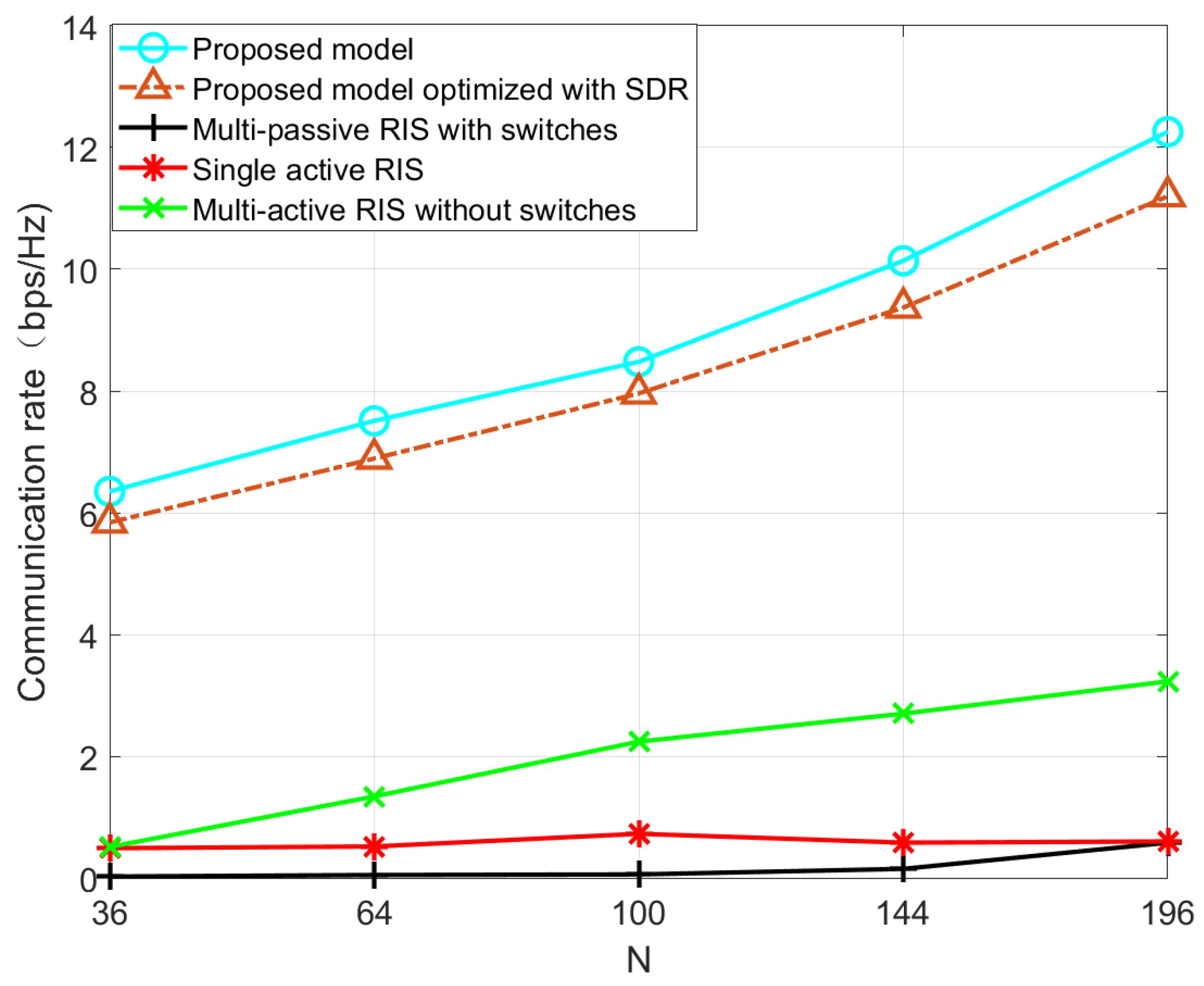
Proposed model: As shown in
Figure 1 and optimized using the above algorithm.
Proposed model optimized with SDR: As shown in
Figure 1 and optimized using the SDR algorithm.
Multi-active RIS without switches: As shown in
Figure 1, but all active RIS are always on.
Multi-passive RIS with switches: As shown in
Figure 1, but replace active RIS with passive RIS. For convenience of comparison, the transmission power of the BS is
Single active RIS: Similar to
Figure 1, but with only one active
. For convenience of comparison, the transmission power and number of units of active RIS are
and
, respectively.
Figure 3 shows the relationship between jamming power and communication rate. It can be seen that when the jamming power is
, the single active RIS-assisted anti-jamming communication has the highest communication rate. But as the jamming power increases, the communication rate decreases sharply, and the proposed algorithm always maintains a high communication rate. This is because in a single-RIS scenario, there are more RIS units and only one dual fading path exists. However, in active RIS-assisted communication with jamming, due to the positive correlation between the jamming channel and the communication channel, adjusting the RIS reflection beam will enhance both the legitimate communication signal and the jamming signal, resulting in a sharp decline in communication performance. The system model proposed in this paper can construct a dynamic heterogeneous redundant channel anti-jamming domain by regulating the RIS switch, making the communication channel irrelevant to the jamming channel. Therefore, optimizing the RIS beam phase to enhance the legitimate communication signal strength while nulling the jamming signal will help to achieve robust anti-jamming communication at high-jamming-power rates.
Figure 4 shows the relationship between the number of RIS units and communication rate. It can be seen that the proposed algorithm can achieve a higher communication rate than other algorithms for different
N. In addition, the communication rate of the proposed algorithm increases with the number of RIS units, whether it is active RIS or passive RIS, while other rates do not. This is because the direction of the BS’s signal and jammer’s signal is consistent, and RIS cannot distinguish between the signal and jamming, and thus is unable to improve the communication rate. However, the proposed algorithm utilizes a redundant channel domain to identify the BS’s signal and jammer’s signal by turning RIS on or off, amplifying the BS’s signal while nulling the jammer’s signal, thereby improving the communication rate.
Figure 5 shows the communication rate of the proposed algorithm for each iteration under different unit numbers. It can be seen that the BCD algorithm basically converges after three iterations, which indicates that the proposed algorithm has a fast and stable convergence rate.

