Abstract
Autonomous underwater vehicles (AUVs) are extensively utilized in various autonomous underwater missions, encompassing ocean environment monitoring, underwater searching, and geological exploration. Owing to their profound underwater capabilities and robust autonomy, AUVs have emerged as indispensable instruments. Nevertheless, AUVs encounter several constraints in the domain of underwater navigation, primarily stemming from the cost-intensive nature of inertial navigation devices and Doppler velocity logs, which impede the acquisition of navigation data. Underwater simultaneous localization and mapping (SLAM) techniques, along with other navigation approaches reliant on perceptual sensors like vision and sonar, are employed to augment the precision of self-positioning. Particularly within the realm of machine learning, the utilization of extensive datasets for training purposes plays a pivotal role in enhancing algorithmic performance. However, it is common for data obtained exclusively from inertial sensors, a Doppler Velocity Log (DVL), and depth sensors in underwater environments to not be publicly accessible. This research paper introduces an underwater navigation dataset derived from a controllable AUV that is equipped with high-precision fiber-optic inertial sensors, a DVL, and depth sensors. The dataset underwent rigorous testing through numerical calculations and optimization-based algorithms, with the evaluation of various algorithms being based on both the actual surfacing position and the calculated position.
1. Introduction
In recent years, AUVs have garnered increasing attention in underwater exploration and military missions [1]. Due to the attenuation of underwater electromagnetic signals, AUVs rely on inertial sensors and acoustic devices for navigation instead of GPS [2,3]. Specifically, for stand-alone strapdown inertial navigation systems (SINS), the estimation of relative velocity and position involves the integration of accelerometer and gyroscope sensor data, which introduces errors and leads to significant drift in the estimated position and velocity [4]. The introduction of a DVL assists navigation by measuring bottom-to-water relative velocity to improve positioning accuracy, but prolonged error accumulation remains a challenge [5]. Navigation methods based on other perceptual sensors, such as vision and sonar, have been applied in specific scenarios but mostly remain in the laboratory stage [6,7]. Limitations in sensing conditions, such as vision being unsuitable in turbid environments and limited acoustic sensing resolution, make perception-based navigation non-universal for underwater applications. In contrast, inertial navigation combined with DVLs and depth sounders has become a mature technology widely used in underwater navigation solutions.
In contrast to indoor settings, the navigation of underwater environments poses significant challenges on a large scale. Consequently, the integration of inertial and Doppler Velocity Log (DVL) navigation techniques can be effectively employed in various scenarios. However, the utilization of optical devices and navigation applications based on structured environments is restricted due to the turbidity and intricacy inherent in natural underwater environments [8]. Concurrently, the high cost of high-precision inertial sensors and sound velocity measurement devices restricts the application and data collection of small AUVs [9]. In particular, the cost of common fiber-optic inertial navigation systems can reach tens of thousands of dollars, making them impractical for small teams. In such cases, the availability of underwater high-precision navigation data allows researchers to analyze the generation and propagation of AUV navigation errors more profoundly and devise strategies to mitigate any potential errors or limitations. This will provide a research foundation for various fields, including marine biology, geology, environmental monitoring, and defense operations [10].
Currently, the collection of AUV navigation data in natural underwater environments is concentrated in authoritative experimental institutions, such as the Naval Surface Warfare Center (NSWC) [11], the Naval Undersea Warfare Center (NUWC) [12], the European Research Agency [13], and the Australian military, etc. [14]. The collection of pertinent data necessitates the utilization of shore-based platforms or motherships, and in intricate environments, human divers are also employed to facilitate navigation, thereby resulting in substantial costs. The range of underwater sensors is limited by the environment, especially in visible light, where active light sources are subject to forward and backward scattering [15]. Acoustic-based forward-looking sonar and side-scan sonar (SSS) are widely used for underwater environment sensing and terrain-matching navigation [16]. Therefore, the collection and organization of underwater datasets will be a high-cost, complex task, and the number of existing publicly available datasets is very small, which reflects this paper’s significance in this work.
In this paper, we present a novel dataset to expand research in underwater navigation. The uniqueness lies in the data sourced from multiple sensors, including high-quality inertial navigation systems (INS) and Differential Global Positioning Systems (DGPS), as well as synchronized DVLs and depth sounder data. In particular, all data are collected in the natural environment, including lakes, reservoirs, and offshore areas. Moreover, the data are generated during the autonomous navigation of the AUV, meaning that the navigation data conform to the kinematics of the vehicle. To the best of our knowledge, this is the first publicly released AUV lake/ocean navigation dataset based on high-precision sensors. The dataset is accessible via the following link: https://github.com/nature1949/AUV_navigation_dataset (accessed on 8 June 2023).
In summary, the main contributions of this article are as follows:
- Presentation of a substantial amount of underwater high-precision navigation data, covering approximately 147 km;
- Collection of data from real scenarios in three different regions, encompassing diverse trajectories and time spans;
- Introduction of navigation challenges in underwater environments and the proposed methods based on dead reckoning and collaborative localization, evaluated against our benchmark.
The paper is structured as follows: Section 2 describes the research foundation and current status of underwater navigation, as well as the characteristics and limitations of publicly available datasets for underwater navigation. Section 3 describes the platforms and sensors used for data acquisition, as well as the acquisition process. Section 4 describes the dataset structure and typical trajectories and tests the dataset by common methods. A discussion of the results and data is carried out in Section 5 and finally summarized in Section 6.
2. Related Work
2.1. Underwater Navigation Methods
Typically, AUVs employ inertial navigation combined with acoustics for collaborative navigation, while ROVs, due to their limited mobility, additionally use visually and acoustically aided navigation. Positioning algorithms often apply filtering or optimization methods, including traditional EKF, UKF, and the latest SLAM techniques, among others. For instance, Harris et al. developed an AUV position estimation algorithm using the ensemble Kalman filter (EnKF) and fuzzy Kalman filter (FKF), which avoids linearization of the AUV’s dynamics model [5]. Jin et al. proposed a single-source assisted passive localization method that combines acoustic positioning with inertial navigation and concluded that time difference of arrival (TDOA) + AOA yields better results [17]. This method utilizes fixed sound sources to periodically emit sound pulses underwater and locate the source using a TDOA positioning technique.
Jorgensen et al. based their approach on the XKF principle and constructed an observer for estimating position, velocity, attitude, underwater wave speed, rate sensor, and accelerometer biases, which demonstrated stability and achieved near-noise optimal performance [18]. Wang et al. integrated depth information into two-dimensional visual images and proposed an online fusion method based on tightly coupled nonlinear optimization to achieve continuous and robust localization in rapidly changing underwater environments [19]. Manderson et al. presented an efficient end-to-end learning approach for training navigation strategies using visual data and demonstrated autonomous visual navigation over a distance of more than one kilometer [20]. Machine learning-based approaches require massive amounts of training data, which highlights the importance of collecting underwater navigation data to enhance the performance of navigation algorithms.
2.2. Underwater Natural Scene Datasets
Publicly available underwater natural scene datasets are continuously released and used for underwater navigation, 3D reconstruction, underwater target recognition, and scene perception. Singh et al. released a marine debris dataset for forward-looking sonar semantic segmentation, which contains typical marine debris segmentation grayscale maps [21]. Zhou et al. constructed a common target detection dataset for sonar image detection and classification, which contained targets such as underwater shipwrecks, wrecks of crashed airplanes, victims, etc. [22]. Zhang et al. disclosed a homemade sonar common target detection dataset and evaluated the performance of a self-trained AutoDL detector [23]. Hou et al. published real side-scan sonar image datasets containing images of different classes of undersea targets and proposed a semi-synthetic data generation method that combines image segmentation with simulation of intensity distributions in different regions using optical images as input [24].
Given the difficulty of acquiring underwater datasets, there are also many researchers investigating deep neural network-based enhancement methods for underwater data. Chang et al. proposed a real-world underwater image dataset (UIDEF) containing multiple degradation types and different shooting perspectives and a color-contrast-complementary image enhancement framework consisting of adaptive chromatic balancing and multiscale weighted fusion [25]. Yin et al. proposed an underwater image restoration (UIR) method based on a convolutional neural network (CNN) architecture and a synthetic underwater dataset that can realize the direct restoration of degraded underwater images [26]. Chen et al. created class-balanced underwater datasets capable of generating underwater datasets with various color distortions and haze effects, and generated class-balanced underwater datasets from the open competition underwater dataset URPC18 via the class-based style enhancement (CWSA) algorithm [27]. Polymenis et al. used object images taken in a controlled laboratory environment to generate underwater images by generative adversarial networks (GANs) in combination with images featuring the underwater environment [28]. Boittiaux et al. provided image datasets from multiple visits to the same hydrothermal vent edifice and estimated camera poses and scenes from navigation data and motion structures. [29]. Extending underwater data through data augmentation methods is a future research direction, but original underwater datasets of natural scenes are still indispensable.
2.3. Underwater Navigation Datasets
The collection of underwater data presents challenges due to costs, technical requirements, and limitations imposed by the underwater environment. Nevertheless, an increasing number of research teams have released datasets related to AUV autonomous navigation, with a focus on easily obtainable visual information. The establishment of these datasets has facilitated the development of AUV technologies, particularly in underwater target recognition and underwater SLAM techniques. For instance, Cheng et al. provided data collected in inland waterways using a stereo camera, LiDAR system, global positioning system antenna, and inertial measurement unit [30]. Song et al. obtained a millimeter-precision underwater visual-inertial dataset through a motion capture system, but the data were acquired in a laboratory setting [31]. Tomasz et al. introduced an underwater visual navigation SLAM dataset that includes ground truth tracking of vehicle positions obtained through underwater motion capture [32].
Martin et al. offered canoe attitude and stereo camera data collected in natural river environments [33]. Panetta et al. presented the Underwater Object Tracking (UOT100) benchmark dataset, which comprises 104 underwater video sequences and over 74,000 annotated frames from natural and artificial underwater videos with various distortions [34]. Angelos et al. provided data collected by AUVs in complex underwater cave systems, particularly equipped with two mechanically scanned imaging sonars [35]. Notably, Kristopher et al. simulated AUV data with advanced sensors by equipping a ground vehicle with two multibeam sonars and a set of navigation sensors [36]. More recently, Maxime et al. collected ROS data for underwater SLAM using a monocular camera, an inertial measurement unit (IMU), and other sensors in harbors and archaeological sites [37]. Li et al. presented an adaptive AUV-assisted ocean current data collection strategy, formulating an optimization problem to maximize the VoI energy ratio, thereby reducing AUV energy consumption and ensuring timely data acquisition [38].
However, the existing datasets primarily concentrate on underwater vision and are obtained from natural environments or created through data augmentation. These datasets are primarily utilized for various applications, including underwater image recognition, underwater 3D reconstruction, and visual/visual-inertial SLAM. However, the availability of independent datasets specifically focused on underwater inertial/DVL navigation remains limited. Therefore, this paper aims to address this gap by compiling AUV navigation data gathered from diverse natural scenarios and presenting it in an enhanced KITTI format, facilitating the extraction of algorithmic data for general purposes.
3. Data Acquisition
3.1. Platform
We used a 325 mm diameter AUV as the acquisition platform and collected data through different trajectories at different times and locations to achieve a diversified data type and a more representative sample set. The platform was equipped with high-precision inertial navigation, differential RTK, DVL, depth finder, and other sensors. The computing platform used a customized motherboard, which allowed different devices access and provided high-speed computing power. The platform structure and sensor layout are shown in Figure 1. The perception and navigation sensors were fixed on the vehicle and could be associated with rigid body transformations, but the provided data were obtained through rotational transformations based on their own sensors.
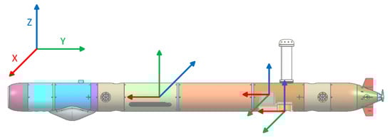
Figure 1.
Schematic diagram of AUV structure and sensor layout.
3.2. Sensor
This section introduces the hardware and software used for data collection, including navigation sensors, DVL, depth sensors, and other payloads. These components work in harmony to capture comprehensive and accurate underwater navigation data. The high-precision fiber-optic inertial navigation system performs inertial measurements, provides six-axis angular velocity and linear acceleration, and has the internal potential for satellite and Doppler fusion. The DVL features a four-phase beam array, allowing it to calculate the vehicle’s velocity relative to the water independently. This additional velocity information contributes to a more comprehensive understanding of the AUV’s motion and aids in precise positioning during underwater navigation. Table 1 lists the complete hardware.

Table 1.
Overview of platform and sensor specifications and performance.
Through the utilization of this sophisticated hardware configuration, we guarantee the attainment of sensor data of exceptional quality, thereby enabling a precise and comprehensive examination of underwater navigation efficacy. The amalgamation of this dataset with the robust and accurate hardware employed presents researchers with a significant resource for the purpose of benchmarking algorithms and assessing navigation performance.
3.3. Data Collection
This dataset was collected from April 2021 to August 2022, spanning 12.63° of longitude and 11.22° of latitude. The data mainly include underwater tracking tasks, surface tracking tasks, and surface manual remote control tasks. Among them, underwater tasks were generally performed at a depth of 10 m to ensure the safety of the equipment. The trajectory estimated from the navigational position does not precisely align with the actual point of departure from the water, indicating a navigation error. Conversely, in surface missions, the presence of GPS signals results in the trajectory error being solely attributed to control error. It should be noted that underwater tasks may be affected by water flow, which limits the accuracy of navigation. However, such data are not allowed to be disclosed at this time. When the surface is moored, drift is generated due to interference from surface factors such as water flow and wind.
3.4. Synchronization
Various sensors first record the timestamp of the captured frames. Through the central processing platform, they are fused with the GPS time and computer time to record events with a time accuracy of 100 ms. For asynchronous inertial and DVL measurements, the lower frequency is mainly recorded. The period is not fixed due to the inconsistent frequencies and times of different sensors.
4. Dataset
4.1. Data Structures
Existing public underwater datasets adopt non-standard data structures based on different types of sensors, which also causes difficulties for researchers to interpret. To unify, this dataset is based on the data structure of the commonly used KITTI car dataset [39] and adds additional data including DVL velocity and depth information. It is finally provided in CSV format, together with Python tools that can be directly transferred to ROS. The file directory structure is shown in Figure 2.
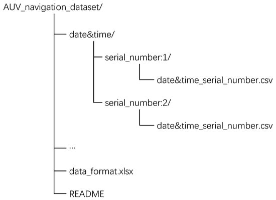
Figure 2.
Directory structure of the file set.
Several typical vehicle trajectories are shown in Figure 3. Note that the dataset contains structured underwater and surface maneuvering trajectories and that switching between surface and underwater sailing also occurs in one segment of the trajectory. We labeled the surface and underwater navigation sections to differentiate between them, while the most significant feature of underwater navigation is the absence of GPS signals, resulting in constant latitude and longitude received from GPS.
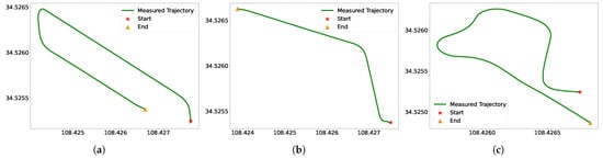
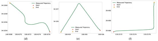
Figure 3.
Various types of AUV tracks in different regions. (a) Scenario 1. (b) Scenario 2. (c) Scenario 3. (d) Scenario 4. (e) Scenario 5. (f) Scenario 6.
Compared with other underwater datasets, most of this dataset is driven autonomously according to the AUV’s own driving method rather than with manual assistance. This is conducive to analyzing the kinematic rules of the AUV. At the same time, underwater navigation based on inertial units inevitably leads to error accumulation, which is fatal to the task. In the dataset, precise global positioning results measured by differential RTK are provided, with RTK base stations deployed on land. During underwater cruising, GPS measurements are unavailable until the AUV surfaces. This helps to determine the accuracy of underwater navigation. The latitude and longitude derived based on waypoints are the initial results of onboard calculations and do not indicate navigation error performance.
4.2. Testing
The mathematical model and engineering implementation of the fiber-optic inertial navigation system are mature cases. In this paper, the performance of the data is initially evaluated by solving the inertial navigation part underwater and comparing it with the initial navigation estimation results. The evaluation uses data acquired from gyroscopes, accelerometers, depth sensors, magnetometers, etc., and performs position estimation after calibration, filtering, and time synchronization. Methods for compensating errors due to underwater welfare, flow, etc., are not the focus of this paper and are to be further investigated.
To begin the evaluation process, we utilize the position and attitude of the AUV at the entry point as the initial state. The initial longitude, latitude, and height values are recorded as and , respectively. The initial velocity is obtained from either the DVL’s effective state or the inertial navigation system. Additionally, the initial strapdown attitude matrix is expressed in (1), providing a reference for the AUV’s initial orientation.
By comparing the results of the inertial navigation solution with those of the initial navigation estimate, we can assess the accuracy and reliability of the fiber-optic inertial navigation system in the underwater environment and verify its ability to provide accurate navigation information to the AUV throughout the underwater mission. Accumulated errors will occur during the solving process, and can be resolved through periodic error correction and position calibration using known landmarks or reference points for accurate navigation [40].
The initial position matrix is expressed as:
The initial angular velocity of the Earth’s rotation is expressed as:
The angular velocity of the AUV, , is calculated based on the output value of the gyroscope. The calculation process is as follows. Compared with the original text, the following optimizations are made:
The quaternion is instantaneously updated using the fourth-order Runge–Kutta method and finally normalized. Over three consecutive sampling periods, , the update equation is expressed as:
At this point, the updated strapdown matrix is shown in (6).
The acceleration output of the accelerometer needs to be transformed from the carrier coordinate system to the navigation coordinate system, that is, . At this point, the acceleration with respect to the ground is shown in (7).
The velocity update is expressed as:
The position angular velocity update equation is:
Due to the slow changes in position during the navigation process, the update of the position matrix can be represented as follows:
At this moment, the position of the AUV is calculated using the following formula:
Here, we assess three representative sequences from the dataset, encompassing distinct movement attributes and geographic regions, as illustrated in Figure 4, Figure 5 and Figure 6. Observing the results, it is evident that the computed velocities and attitude angles align well with the initial data. While the altitude direction remains linked to the resolved velocity, depth gauge measurements offer increased reliability. The deviation between the updated trajectory from the odometer and the measured trajectory, which does not accurately represent the true values, results from the accumulation of measurement errors.
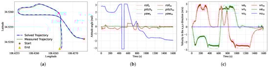
Figure 4.
A comparison between the solved and measured values for Case 1 is presented. The subscript “s” denotes the solved result, while the subscript “m” indicates the measured result. (a) entails a comparison between the initial heading projection position and the solved position. (b) involves a comparison between the measured attitude and the solved attitude. Lastly, (c) examines the contrast between the measured and solved velocity values in the northeast sky direction.
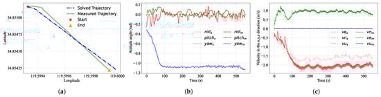
Figure 5.
A comparison between the solved and measured values for Case 2 is presented. The subscript “s” denotes the solved result, while the subscript “m” indicates the measured result. (a) entails a comparison between the initial heading projection position and the solved position. (b) involves a comparison between the measured attitude and the solved attitude. Lastly, (c) examines the contrast between the measured and solved velocity values in the northeast sky direction.
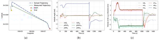
Figure 6.
A comparison between the calculated and measured values for Case 3 is presented. The subscript “s” denotes the solved result, while the subscript “m” indicates the measured result. (a) entails a comparison between the initial heading projection position and the calculated position. (b) involves a comparison between the measured attitude and the calculated attitude. Lastly, (c) examines the contrast between the measured and calculated velocity values in the northeast sky direction.
For independent strapdown inertial navigation systems (SINS), the estimation of relative velocity and position involves the integration of accelerometer and gyro sensor data, which can introduce errors and result in significant drift in the estimated position and velocity [4]. Integrating the DVL and depth gauge measurements would notably enhance underwater navigation precision, even though the challenge of mitigating errors persists.
5. Discussion
Navigation data on lakes and oceans were gathered by employing autonomous underwater vehicles (AUVs) equipped with rudimentary sensors. The trajectories and performance of the navigation data were acquired via dead-reckoning. By considering diving points and upper floating points, the underwater state of the vehicle can be ascertained and examined for diverse trajectories. In particular, the kinematic model of the AUV enables a meticulous analysis of its navigation trajectory attributes, thereby facilitating the augmentation of precision in underwater navigation. Extensive scholarly investigations have been conducted on fusion navigation algorithms for IMU/DVL. However, it is of utmost importance to conduct an integrated evaluation that incorporates openly accessible datasets. The profusion of underwater navigation data presents a valuable resource for comprehensively analyzing the interdependent connection between navigation strategies and devices, thereby revealing possibilities for attaining high-precision navigation through cost-effective sensor solutions. Additionally, future endeavors will explore applications of the navigation dataset.
Until new and efficient means of underwater navigation are developed, the capacity of AUVs to achieve high-precision navigation remains constrained by cost and technological limitations. The predominant approach to AUV navigation is centered on aided navigation techniques based on inertial navigation principles and amalgamating diverse measurements [41]. However, the complex interaction of practical environmental limitations, hydroacoustic channel multipath effects, and submerged ambient noise interference often leads to significant irregularities [42]. Consequently, addressing these challenges, such as mitigating cumulative errors arising from inertial navigation and rectifying measurement inaccuracies from various sensors, becomes a crucial focus for future research efforts.
In future work, we plan to expand our dataset further by incorporating additional sensing modalities, such as perception and acoustic data, to extend its usability. Specifically, we are interested in exploring underwater SLAM techniques based on forward-looking and side-scan sonar data, which will open up new avenues in underwater navigation. Moreover, data-driven pedestrian dead reckoning (PDR) research has already shown promising results with extensive datasets, inspiring us to further improve underwater navigation accuracy through large-scale learning approaches.
6. Conclusions
We have compiled a navigation dataset of AUVs operating in various regions, collected using high-precision inertial navigation, DVL, and depth sensors. The dataset encapsulates a myriad of natural scenarios involving AUVs navigating in both underwater and surface environments and spanning diverse latitudes, longitudes, and timelines. This dataset represents a pioneering collection of underwater navigation data obtained through the combination of high-cost fiber-optic gyroscopes. Drawing upon our dataset, we offer significant data support for the enhancement of underwater navigation algorithms. The assessment of typical algorithms has substantiated the practicality and effectiveness of our dataset. We hope that this dataset will be beneficial to other researchers in the field of autonomous exploration in constrained underwater environments.
Author Contributions
Conceptualization, C.W. and F.Z.; methodology, C.W.; software, C.W. and C.C.; validation, D.Y.; investigation, F.Z.; resources, F.Z. and G.P.; formal analysis, C.C. and D.Y.; writing—original draft preparation, C.W. and C.C.; writing—review and editing, C.W. and F.Z.; visualization, C.W. and C.C.; supervision, F.Z.; project administration, F.Z. and G.P.; funding acquisition, F.Z. All authors have read and agreed to the published version of the manuscript.
Funding
This research was funded by the National Natural Science Foundation of China (52171322), the National Key Research and Development Program (2020YFB1313200), and the Fundamental Research Funds for the Central Universities (D5000210944).
Data Availability Statement
Data available in a publicly accessible repository. The data presented in this study are openly available in the AUV_navigation_dataset at https://github.com/nature1949/AUV_navigation_dataset (accessed on 8 June 2023).
Acknowledgments
The authors gratefully acknowledge the support provided by the Key Laboratory of Unmanned Underwater Transport Technology during the data collection process, as well as the assistance of the research team members.
Conflicts of Interest
The authors declare no conflict of interest.
Abbreviations
The following abbreviations are used in this manuscript:
| AUV | Autonomous underwater vehicle |
| DVL | Doppler Velocity Log |
| SLAM | Simultaneous localization and mapping |
| DGPS | Differential Global Positioning Systems |
| SINS | Strapdown inertial navigation systems |
| INS | Inertial navigation systems |
| IMU | Inertial measurement unit |
| TDOA | Time difference of arrival |
References
- Lapierre, L.; Zapata, R.; Lepinay, P.; Ropars, B. Karst exploration: Unconstrained attitude dynamic control for an AUV. Ocean Eng. 2021, 219, 108321. [Google Scholar] [CrossRef]
- Yan, J.; Ban, H.; Luo, X.; Zhao, H.; Guan, X. Joint Localization and Tracking Design for AUV With Asynchronous Clocks and State Disturbances. IEEE Trans. Veh. Technol. 2019, 68, 4707–4720. [Google Scholar] [CrossRef]
- Liu, R.; Liu, F.; Liu, C.; Zhang, P. Modified Sage-Husa Adaptive Kalman Filter-Based SINS/DVL Integrated Navigation System for AUV. J. Sens. 2021, 2021, 9992041. [Google Scholar] [CrossRef]
- Sahoo, A.; Dwivedy, S.K.; Robi, P. Advancements in the field of autonomous underwater vehicle. Ocean Eng. 2019, 181, 145–160. [Google Scholar] [CrossRef]
- Harris, Z.J.; Whitcomb, L.L. Cooperative acoustic navigation of underwater vehicles without a DVL utilizing a dynamic process model: Theory and field evaluation. J. Field Robot. 2021, 38, 700–726. [Google Scholar] [CrossRef]
- Bucci, A.; Zacchini, L.; Franchi, M.; Ridolfi, A.; Allotta, B. Comparison of feature detection and outlier removal strategies in a mono visual odometry algorithm for underwater navigation. Appl. Ocean Res. 2022, 118, 102961. [Google Scholar] [CrossRef]
- Franchi, M.; Ridolfi, A.; Zacchini, L. 2D Forward Looking SONAR in Underwater Navigation Aiding: An AUKF-based strategy for AUVs*. IFAC-Papersonline 2020, 53, 14570–14575. [Google Scholar] [CrossRef]
- Zhou, W.H.; Zhu, D.M.; Shi, M.; Li, Z.X.; Duan, M.; Wang, Z.Q.; Zhao, G.L.; Zheng, C.D. Deep images enhancement for turbid underwater images based on unsupervised learning. Comput. Electron. Agric. 2022, 202, 107372. [Google Scholar] [CrossRef]
- Su, R.; Zhang, D.; Li, C.; Gong, Z.; Venkatesan, R.; Jiang, F. Localization and Data Collection in AUV-Aided Underwater Sensor Networks: Challenges and Opportunities. IEEE Netw. 2019, 33, 86–93. [Google Scholar] [CrossRef]
- Howe, J.A.; Husum, K.; Inall, M.E.; Coogan, J.; Luckman, A.; Arosio, R.; Abernethy, C.; Verchili, D. Autonomous underwater vehicle (AUV) observations of recent tidewater glacier retreat, western Svalbard. Mar. Geol. 2019, 417, 106009. [Google Scholar] [CrossRef]
- Gallagher, D.G.; Manley, R.J.; Hughes, W.W.; Pilcher, A.M. Development of an enhanced underwater navigation capability for military combat divers. In Proceedings of the OCEANS 2016 MTS/IEEE Monterey, Monterey, CA, USA, 19–23 September 2016; pp. 1–4. [Google Scholar] [CrossRef]
- Dzikowicz, B.R.; Yoritomo, J.Y.; Heddings, J.T.; Hefner, B.T.; Brown, D.A.; Bachand, C.L. Demonstration of Spiral Wavefront Navigation on an Unmanned Underwater Vehicle. IEEE J. Ocean. Eng. 2023, 48, 297–306. [Google Scholar] [CrossRef]
- Huet, C.; Mastroddi, F. Autonomy for Underwater Robots—A European Perspective. Auton. Robot. 2016, 40, 1113–1118. [Google Scholar] [CrossRef][Green Version]
- Bil, C. Concept Evaluation of a Bi-Modal Autonomous System. In Proceedings of the AIAA AVIATION 2023 Forum, San Diego, CA, USA, 12–16 June 2023. [Google Scholar] [CrossRef]
- Li, H.; Zhu, J.; Deng, J.; Guo, F.; Zhang, N.; Sun, J.; Hou, X. Underwater active polarization descattering based on a single polarized image. Opt. Express 2023, 31, 21988–22000. [Google Scholar] [CrossRef]
- Franchi, M.; Ridolfi, A.; Pagliai, M. A forward-looking SONAR and dynamic model-based AUV navigation strategy: Preliminary validation with FeelHippo AUV. Ocean Eng. 2020, 196, 106770. [Google Scholar] [CrossRef]
- Jin, B.; Xu, X.; Zhu, Y.; Zhang, T.; Fei, Q. Single-Source Aided Semi-Autonomous Passive Location for Correcting the Position of an Underwater Vehicle. IEEE Sens. J. 2019, 19, 3267–3275. [Google Scholar] [CrossRef]
- Jorgensen, E.K.; Fossen, T.I.; Bryne, T.H.; Schjolberg, I. Underwater Position and Attitude Estimation Using Acoustic, Inertial, and Depth Measurements. IEEE J. Ocean. Eng. 2020, 45, 1450–1465. [Google Scholar] [CrossRef]
- Wang, Y.; Ma, X.; Wang, J.; Wang, H. Pseudo-3D Vision-Inertia Based Underwater Self-Localization for AUVs. IEEE Trans. Veh. Technol. 2020, 69, 7895–7907. [Google Scholar] [CrossRef]
- Manderson, T.; Gamboa Higuera, J.C.; Wapnick, S.; Tremblay, J.F.; Shkurti, F.; Meger, D.; Dudek, G. Vision-Based Goal-Conditioned Policies for Underwater Navigation in the Presence of Obstacles. arXiv 2020, arXiv:2006.16235. [Google Scholar]
- Singh, D.; Valdenegro-Toro, M. The Marine Debris Dataset for Forward-Looking Sonar Semantic Segmentation. In Proceedings of the 2021 IEEE/CVF International Conference on Computer Vision Workshops (ICCVW), Virtual, 11–17 October 2021; pp. 3734–3742. [Google Scholar]
- Zhou, Y.; Chen, S.; Wu, K.; Ning, M.; Chen, H.; Zhang, P. SCTD 1.0:Sonar Common Target Detection Dataset. Comput. Sci. 2021, 48, 334–339. [Google Scholar] [CrossRef]
- Zhang, P.; Tang, J.; Zhong, H.; Ning, M.; Liu, D.; Wu, K. Self-Trained Target Detection of Radar and Sonar Images Using Automatic Deep Learning. IEEE Trans. Geosci. Remote Sens. 2022, 60, 1–14. [Google Scholar] [CrossRef]
- Huo, G.; Wu, Z.; Li, J. Underwater Object Classification in Sidescan Sonar Images Using Deep Transfer Learning and Semisynthetic Training Data. IEEE Access 2020, 8, 47407–47418. [Google Scholar] [CrossRef]
- Chang, L.; Song, H.; Li, M.; Xiang, M. UIDEF: A real-world underwater image dataset and a color-contrast complementary image enhancement framework. ISPRS J. Photogramm. Remote Sens. 2023, 196, 415–428. [Google Scholar] [CrossRef]
- Yin, X.; Liu, X.; Liu, H. FMSNet: Underwater Image Restoration by Learning from a Synthesized Dataset. In Proceedings of the Artificial Neural Networks and Machine Learning—ICANN 2021, Bratislava, Slovakia, 14–17 September 2021; Farkaš, I., Masulli, P., Otte, S., Wermter, S., Eds.; Springer: Cham, Switzerland, 2021; pp. 421–432. [Google Scholar]
- Chen, L.; Dong, J.; Zhou, H. Class balanced underwater object detection dataset generated by class-wise style augmentation. arXiv 2021, arXiv:2101.07959. [Google Scholar]
- Polymenis, I.; Haroutunian, M.; Norman, R.; Trodden, D. Artificial Underwater Dataset: Generating Custom Images Using Deep Learning Models. In Proceedings of the ASME 2022 41st International Conference on Ocean, Offshore and Arctic Engineering, Hamburg, Germany, 5–10 June 2022. [Google Scholar] [CrossRef]
- Boittiaux, C.; Dune, C.; Ferrera, M.; Arnaubec, A.; Marxer, R.; Matabos, M.; Audenhaege, L.V.; Hugel, V. Eiffel Tower: A deep-sea underwater dataset for long-term visual localization. Int. J. Robot. Res. 2023, 02783649231177322. [Google Scholar] [CrossRef]
- Cheng, Y.; Jiang, M.; Zhu, J.; Liu, Y. Are We Ready for Unmanned Surface Vehicles in Inland Waterways? The USVInland Multisensor Dataset and Benchmark. IEEE Robot. Autom. Lett. 2021, 6, 3964–3970. [Google Scholar] [CrossRef]
- Song, Y.; Qian, J.; Miao, R.; Xue, W.; Ying, R.; Liu, P. HAUD: A High-Accuracy Underwater Dataset for Visual-Inertial Odometry. In Proceedings of the 2021 IEEE Sensors, 31 October–3 November 2021; pp. 1–4. [Google Scholar] [CrossRef]
- Luczynski, T.; Scharff Willners, J.; Vargas, E.; Roe, J.; Xu, S.; Cao, Y.; Petillot, Y.; Wang, S. Underwater inspection and intervention dataset. arXiv 2021, arXiv:2107.13628. [Google Scholar] [CrossRef]
- Miller, M.; Chung, S.J.; Hutchinson, S. The Visual–Inertial Canoe Dataset. Int. J. Robot. Res. 2018, 37, 13–20. [Google Scholar] [CrossRef]
- Panetta, K.; Kezebou, L.; Oludare, V.; Agaian, S. Comprehensive Underwater Object Tracking Benchmark Dataset and Underwater Image Enhancement With GAN. IEEE J. Ocean. Eng. 2022, 47, 59–75. [Google Scholar] [CrossRef]
- Mallios, A.; Vidal, E.; Campos, R.; Carreras, M. Underwater caves sonar data set. Int. J. Robot. Res. 2017, 36, 1247–1251. [Google Scholar] [CrossRef]
- Krasnosky, K.; Roman, C.; Casagrande, D. A bathymetric mapping and SLAM dataset with high-precision ground truth for marine robotics. Int. J. Robot. Res. 2022, 41, 12–19. [Google Scholar] [CrossRef]
- Ferrera, M.; Creuze, V.; Moras, J.; Trouvé-Peloux, P. AQUALOC: An underwater dataset for visual–inertial–pressure localization. Int. J. Robot. Res. 2019, 38, 1549–1559. [Google Scholar] [CrossRef]
- Li, Y.; Sun, Y.; Ren, Q.; Li, S. AUV-Aided Data Collection Considering Adaptive Ocean Currents for Underwater Wireless Sensor Networks. China Commun. 2023, 20, 356–367. [Google Scholar] [CrossRef]
- Geiger, A.; Lenz, P.; Stiller, C.; Urtasun, R. Vision meets robotics: The KITTI dataset. Int. J. Robot. Res. 2013, 32, 1231–1237. [Google Scholar] [CrossRef]
- Wang, C.; Cheng, C.; Yang, D.; Pan, G.; Zhang, F. AUV planning and calibration method considering concealment in uncertain environments. Front. Mar. Sci. 2023, 10, 1228306. [Google Scholar] [CrossRef]
- Zhai, W.; Wu, J.; Chen, Y.; Jing, Z.; Sun, G.; Hong, Y.; Fan, Y.; Fan, S. Research on Underwater Navigation and Positioning Method Based on Sea Surface Buoys and Undersea Beacons. In Proceedings of the China Satellite Navigation Conference (CSNC) 2020 Proceedings, Chengdu, China, 22–25 November 2020; Sun, J., Yang, C., Xie, J., Eds.; Springer: Singapore, 2020. Volume III. pp. 390–404. [Google Scholar]
- Wang, J.; Zhang, T.; Jin, B.; Zhu, Y.; Tong, J. Student’s t-Based Robust Kalman Filter for a SINS/USBL Integration Navigation Strategy. IEEE Sens. J. 2020, 20, 5540–5553. [Google Scholar] [CrossRef]
Disclaimer/Publisher’s Note: The statements, opinions and data contained in all publications are solely those of the individual author(s) and contributor(s) and not of MDPI and/or the editor(s). MDPI and/or the editor(s) disclaim responsibility for any injury to people or property resulting from any ideas, methods, instructions or products referred to in the content. |
© 2023 by the authors. Licensee MDPI, Basel, Switzerland. This article is an open access article distributed under the terms and conditions of the Creative Commons Attribution (CC BY) license (https://creativecommons.org/licenses/by/4.0/).