Abstract
Bond wire fatigue is a prominent problem affecting the reliability of IGBT modules and power electronic converters, and has thus received much attention in the research community. As bond wire fatigue leads to changes in the gate circuit parameters, it affects the IGBT turn-off process. Based on this finding, this paper proposes a fatigue evaluation method for bond wire based on IGBT turn-off time. This includes constructing a turn-off time-bond wire fatigue model that considers the impact of changes in collector current, and developing a control software that utilizes the coupling relationship between the Kelvin terminal voltage VeE and turn-off time for the online extraction of IGBT turn-off time. In summary, the proposed online monitoring method of IGBT bond wire fatigue based on turn-off time can help improve the reliability of power electronic converters.
1. Introduction
The IGBT can achieve high efficiency, great performance and has wide application prospects in electric traction, electric vehicles, aerospace and renewable energy power generation. However, with the improvement of the carrier density and withstanding voltage level of IGBTs, the electrical, thermal and mechanical loads on IGBT modules have become increasingly heavy. Therefore, the reliability of the IGBT module has become a critical issue and limits power electronics converters’ application [1,2,3,4]. According to a survey, IGBT module failure accounts for 34% of power electronic converter failure [5]. Hence, it is necessary to research the reliability of the IGBT module. The failure modes of IGBT modules are generally divided into two categories: IGBT chip failure and module packaging failure. According to research reports, module packaging failure is the main manifestation of IGBT module aging failure. Bond wire serves as a channel for energy exchange between the IGBT chip and the copper substrate, and thus its reliability is of significant concern. Due to the different thermal expansion coefficients of the bond wire material, IGBT chip material and copper substrate material, as the joint part, the heels of bond wire on the substrate and chip both suffer transverse or longitudinal electro-thermal stresses under high temperature and loading current, leading to a significant impact on the reliability of the joint part. Furthermore, since IGBT modules mainly operate in switching states, the reliability issues of heel of bond wire are further accelerated. Consequently, bond wire is the most vulnerable electrical component in an IGBT module, which is prone to cracking and even liftoff and is regarded as a principal module packaging failure mode [6,7].
The physical manifestations of bond wire fatigue are primarily characterized by the appearance of cracks, warping and fractures at the heel of the bond wire [8,9]. As a result, the bond wire resistance increases and the active capacitance area decreases, leading to changes in IGBT switching characteristics and losses. This increases the electro-thermal stress on the bond wire, further raising the risk of bond wire fatigue [10,11,12]. The bond wire fatigue occurs inside the IGBT module and it is difficult to distinguish from the module external features [13,14]. Many methods are applied to the reliability evaluation of the bond wire in IGBT modules, which are mainly divided into three categories. One approach to evaluating the fatigue level of bond wires in IGBT modules involves summarizing the relationship between bond wire fatigue level, power cycling time and junction temperature using an IGBT power cycling platform and assessing the fatigue level of bond wires [10,15], and this needs a lot of time and data. In addition, the power cycling platform is aimed at the comprehensive aging of the IGBT module, so the fatigue type of the module is not accurate, which cannot help module testing engineers quickly analyze the weak links of the module. Furthermore, considering that the existing power cycling platforms do not support the switching of multiple operating conditions, the constructed prediction models do not match the actual operating conditions. The second method involves using active signal measurement to detect the health status of bond wires inside the module. The references [16,17,18,19,20] use an external signal generation device to send sound waves, electrical pulses and other signals to the IGBT module, and the module’s bond wire fatigue degree were evaluated by analyzing the feedback signals, involving Ultrasound Resonators with Spread Spectrum Time Domain Reflectometry. However, the huge equipment and cumbersome detection conditions greatly limit the application of this method. The third method involves using passive signal measurement to identify the health status of bond wires inside the module based on characteristic changes in the signals of the IGBT module terminals. As mentioned earlier, bond wire fatigue can cause an increase in resistance and a decrease in gate capacitance, directly affecting the switching characteristics of the IGBT [21]. Reference [22] used the completion time of gate charging with a constant current source as the characteristic parameter for evaluating bond wire fatigue. Nevertheless, implementing online monitoring requires modification of the driving circuit. Reference [23] utilized overvoltage in the gate voltage during the turn-on process as a characteristic parameter for evaluating bond wire fatigue, which can effectively detect the impact of bond wire fatigue. Considering that bond wire fatigue affects both the input capacitance and inductance of the gate circuit, further research is needed to investigate its specific mechanism. Reference [24] proposed using the ringing characteristics of the voltage during the turn-off process as a characteristic parameter for bond wire fatigue. This parameter can be conveniently used as an online monitoring parameter. Because the turn-off peak voltage is relatively large in normal operating conditions, the influence of measurement probe errors may mask this characteristic. Reference [25] used the transmission characteristics of the IGBT as a characteristic parameter for bond wire fatigue. Because it is difficult to obtain the transmission characteristics of the IGBT under online operating conditions, this parameter is not suitable for online monitoring. Reference [26] proposed using the voltage undershoot in the collector–emitter voltage during the turn-on process as a characteristic parameter for bond wire fatigue. This parameter can be used as an online monitoring parameter, but this characteristic is also susceptible to errors introduced by the measurement probe. References [27,28,29,30,31] utilize the characteristics of the I–V curve of an IGBT and the different operating conditions of power electronic converters and use on-state voltage as a characteristic parameter for the online monitoring of bond wire fatigue. However, the small conduction on-state voltage of IGBTs and the significant impact of changes in collector current on the measurement can lead to less accurate monitoring of bond wire fatigue using this method. Reference [32] improves the aforementioned limitations and further enhances the accuracy of online detection for bond wire fatigue. After analyzing the relationship between Vceon, junction temperature Tj and bond wire fatigue, Reference [33] utilizes an artificial neural network algorithm to evaluate the level of bond wire fatigue. Reference [34] utilized the characteristics of the saturation region of the IGBT and used dVce/dic as a characteristic parameter for bond wire fatigue. It is worth noting that the IGBT needs to be operated within the saturation region, which is not applicable to normal operating conditions of the IGBT, and therefore this parameter is not suitable as a characteristic parameter for online monitoring of bond wire fatigue. Reference [35] utilizes the aging rate constant K of the IGBT module’s thermal resistance to characterize bond wire fatigue. This may provide a novel approach for the online detection of bond wire fatigue in IGBT modules.
This paper proposes a method for the online monitoring of bond wire fatigue using the turn-off time of the IGBT. Compared with detection equipment such as ultrasound and signal generators, extracting the turn-off time does not require complex equipment and does not take up a large space. In addition, the turn-off time itself is an indicator of the dynamic characteristics of the IGBT, and therefore the bond wire fatigue status based on the turn-off time has the conditions for implementing online monitoring. The existence of the Kelvin terminals of the IGBT module enables the convenient and fast extraction of the turn-off time. Compared with the measurement error of the characteristic parameter amplitude, the measurement of turn-off time is relatively more accurate. Given the above conditions, this paper constructed an online turn-off time extraction tool for IGBTs using the communication function of an oscilloscope, which was successfully applied to online monitoring of the turn-off time of IGBTs in power electronic converters. The continuous wavelet transform was also applied to analyze and process the extracted data, which further improved the accuracy of the turn-off time extraction.
2. Relationship between Bond Wire Fatigue and IGBT Turn-Off Time
In this section, an equivalent circuit diagram of an IGBT was constructed based on the physical structure schematic of trench gate IGBTs. Subsequently, the inherent relationship between the time of each stage of the IGBT turn-off process and bond wire fatigue was analyzed, by combining them with the actual turn-off process waveform of the IGBT.
2.1. IGBT Physical Structure and Equivalent Circuit Model
The Figure 1 show the physical structure diagram and equivalent circuit diagram of the IGBT. Thus, the relationship between equivalent circuit parameters and physical structural features can be obtained.
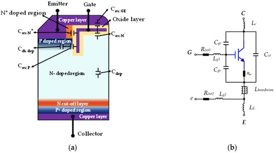
Figure 1.
Schematic diagram of IGBT physical structure (a); IGBT equivalent circuit (b).
The correspondence between the capacitance of the equivalent circuit model and the capacitance of the IGBT physical structure in Figure 1b is shown in Equation (1).
In Equation (1), Cge, Cgc, Cce is the equivalent capacitance of the IGBT, Cox-GE represents the oxide layer capacitance between terminal G and terminal E, Cox-N+ represents the oxide layer capacitance between terminal G and highly doped N-type semiconductors, Cox-N− represents the oxide layer capacitance between terminal G and low-doped N-type semiconductors, Cox-P represents the oxide layer capacitance between terminal G and P-type semiconductor, Cdep represents the depletion region capacitance in the N-type drift region, Cch-dep represents the depletion region capacitance of the channel and Cp + n represents the junction capacitance.
The constituent parameters in Equation (1), such as Cox, etc., can be obtained from Equation (2):
where, AN+, AN−, AP and Ach, respectively denote the areas of the oxide layers in contact with the chip; Cox is the specific oxide capacitance and refers to the capacitance per unit area of the oxide layer; Cdep is the specific space charge capacitance; ΔVT is the voltage of the space charge region in NA doped concentration semiconductors; ε0 and εr denote the vacuum permittivity and the relative permittivity of silicon, respectively; d is the thickness of the oxide layer [36]. The above equation will provide sufficient support for subsequent analysis.
2.2. Analysis of the IGBT Turn-Off Process
According to the definition of the IEC standard for the turn-off process of IGBTs, the turn-off process can be divided into three stages, each of which is described by different electrical parameters. In this article, we will start with the three stages of the turn-off process and analyze in detail the impact of wire bond fatigue on the time of each stage of the IGBT turn-off process based on theoretical derivation formulas, providing theoretical support for the subsequent evaluation of the turn-off time and bond wire fatigue [37,38].
As shown in Figure 2, the duration of the first stage starts from the decline of the driving voltage Vge to the point where the collector current Ic begins to decrease. As the collector current Ic starts to decrease, the collector–emitter voltage Vce rapidly rises. The duration of the second stage starts from the point where the collector current Ic begins to decrease and continues until the collector–emitter voltage Vce rises to the DC bus voltage. The duration of the third stage starts from the point where the collector–emitter voltage Vce rises to the DC bus voltage and continues until the collector current Ic decreases to its initial value of 10%, indicating the disappearance of the voltage generated by the parasitic inductance in the collector–emitter circuit.
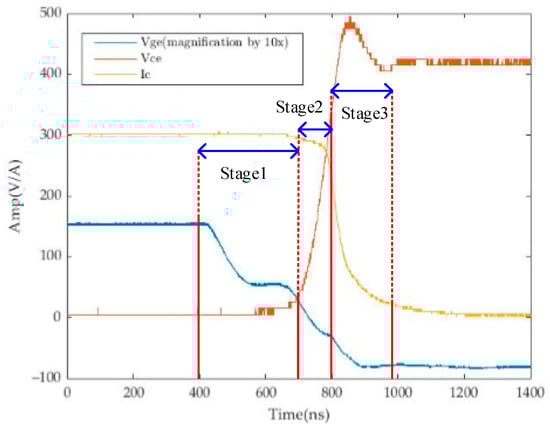
Figure 2.
The schematic diagram of IGBT turn-off process.
The time of stage 1 of the turn-off process can be obtained from Equation (3).
where Rg is the drive resistance, Vgon is the positive value of drive voltage, Vgp is the Miller platform voltage and Vdc is DC source voltage.
The time of stage 2 is considered as the voltage rise time, so it can be obtained using Equation (4):
It should be noted that during the process of voltage rise, the drive current ig is considered to maintain a constant value [37,38].
Since the current drop time of the IGBT is determined by the recombination effect of carriers in the internal storage charge region, the time of stage 3 is considered as the current drop time. The current drop time can be obtained from the internal carrier recombination process model, and its duration can be calculated using Equation (5) [39].
In Equation (5), Da is the bipolar diffusion coefficient, A is the current active area, e0 is the initial charge layer width, un, up is the carrier mobility of electrons and holes, and p0 is the minority carrier concentration near the emitter in the N-type drift region.
2.3. Mechanism of Bond Wire Fatigue Affecting IGBT Turn-off Process
An IGBT chip is composed of multiple cells and is connected by bond wires to achieve the designed current capacity. Figure 3 shows the relative positions between the bond wires and IGBT cells.
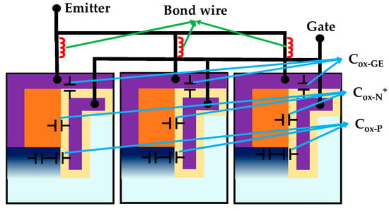
Figure 3.
Position relationship between IGBT chips and bond wires.
Bond wire fatigue can cause failures in the connection between the chip and the copper substrate, resulting in a reduction in the active area of the chip [13]. As shown in Equation (2), the capacitance between the oxide layer and the chip that are in contact with each other decreases as the active area decreases, which in turn leads to a decrease in the capacitance of the equivalent circuit of the IGBT. By combining Equations (1) and (2), it can be seen that as the active area decreases, the capacitances of Cox-GE, Cox-N+ and Cox-N− decrease, resulting in a decrease in gate capacitance Cge, Miller capacitance Cgc and output capacitance Cce.
Therefore, according to Equations (3) and (4), it can be concluded that the duration of stage 1 and stage 2 of the turn-off process will decrease as the gate capacitance Cge and Miller capacitance Cgc decrease. In addition, as shown in Equation (5), the duration of stage 3 is also determined by the change in the active area A, so when the active area A decreases, the duration of the third stage will also decrease. The turn-off time is composed of the durations of the three stages of the turn-off process, so bond wire fatigue can lead to a reduction in the turn-off time of the IGBT.
3. Experimental Verification
In this section, using the SRE100N065FSUT1M2 module as an example, the correctness of the theoretical analysis was experimentally verified by performing dynamic characteristic tests. A turn-off time model for the module was established, providing a theoretical foundation for the online monitoring of bond wire fatigue in IGBT modules.
3.1. Experimental Conditions and Platform
To verify the relationship between bond wire fatigue and turn-off time, dynamic characteristic tests were performed on IGBT modules using a dynamic characteristic test platform developed in our laboratory. The experimental platform is shown in Figure 4 and experimental parameters are shown in Table 1.
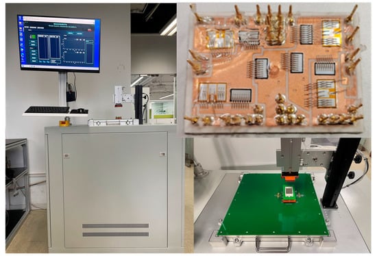
Figure 4.
IGBT dynamic testing platform (left), platform detail (lower right) view, and SRE100N065FSUT1M2 (upper right).

Table 1.
Experimental condition settings.
The experimental platform and SRE100N065FSUT1M2 module are shown in Figure 4.
The dynamic testing platform supports a drive voltage of ±20 V, drive resistance of 3.3/7/10/20/40/50 Ω, load inductance ranging from 20 to 200 µH, loop parasitic parameters less than 50 nH, and is compatible with Flow0, Flow1, Flow2 and Easy2B packaging, and the dynamic testing parameter extraction algorithms are developed in accordance with IEC standards.
3.2. Experimental Result
In this part, the changes in the reference parameters corresponding to the three stages of the turn-off process under different wire bond wire fatigue states were recorded, starting from the three stages of the turn-off process. The correctness of the theoretical analysis in the previous section was verified. In this paper, the bond wire fatigue level was simulated by cutting the bond wires.
The duration of stage 1 of the turn-off process is reflected by the decrease in gate voltage Vge. Therefore, by comparing the gate voltage change during the turn-off process of the IGBT under different wire bond fatigue levels, the relationship can be obtained, as shown in Figure 5.
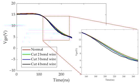
Figure 5.
Relationship between the duration of stage 1 of the turn-off process and bond wire fatigue.
According to the derivation of Equations (1)–(3), it can be concluded that the level of bond wire fatigue is inversely proportional to the duration of stage 1 of the turn-off process. Figure 5 demonstrates the correctness of this theory very well.
Similarly, the duration of stage 2 of the turn-off process is reflected by the rise time of the collector–emitter voltage Vce. Therefore, by comparing the voltage rise process during the turn-off process of the IGBT under different bond wire fatigue levels, the relationship can be obtained, as shown in Figure 6.
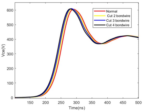
Figure 6.
Relationship between the duration of stage 2 of the turn-off process and bond wire fatigue.
According to the derivation of Equations (1), (2) and (4), it can be concluded that the level of bond wire fatigue is inversely proportional to the duration of stage 2 of the turn-off process. The rise time of the collector–emitter voltage in Figure 6 demonstrates the correctness of this theory very well.
Similarly, the duration of stage 3 of the turn-off process is reflected by the decrease in collector current Ic during the turn-off process. Thus, by comparing the change in the collector current during the turn-off process of the IGBT under different bond wire fatigue levels, the relationship can be obtained, as shown in Figure 7.
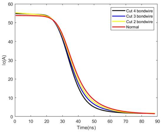
Figure 7.
Relationship between the duration of stage 3 of the turn-off process and bond wire fatigue.
According to the derivation of Equations (1), (2) and (5), it can be concluded that the level of bond wire fatigue is inversely proportional to the duration of stage 3 of the turn-off process. The decreased time for the collector current in Figure 7 demonstrates the correctness of this theory very well.
3.3. Modeling Bond Wire Fatigue and Turn-Off Time Considering Collector Current Variation
Based on the analysis of the experimental results and data organization mentioned above, the relationship between IGBT turn-off time, bond wire fatigue level and collector current amplitude is shown in Figure 8.
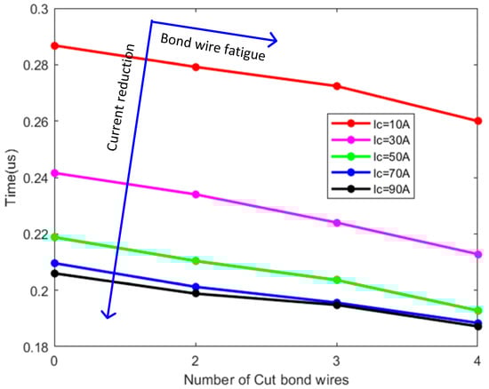
Figure 8.
Relationship between turn-off time, bond wire fatigue and collector current amplitude.
From Figure 8, it can be seen that the turn-off time of the IGBT gradually decreases as the bond wire fatigue level deepens. However, with the variation in the collector current, the turn-off time of the IGBT may exceed the bond wire fatigue level. Therefore, when monitoring bond wire fatigue based on turn-off time, the influence of collector current variation should be eliminated.
By fitting the above data using linear regression, a data-based fitting result can be obtained, as shown in Equation (5):
where X represents the number of cut bond wires. Based on the fitting results of the above data, summarizing the parameters corresponding to the fitting equation can result in a more general bond wire fatigue model based on turn-off time, considering the collector current, as shown in Equation (7).
To verify the fitting accuracy of the model, some data in Figure 9 were compared with the fitted model.
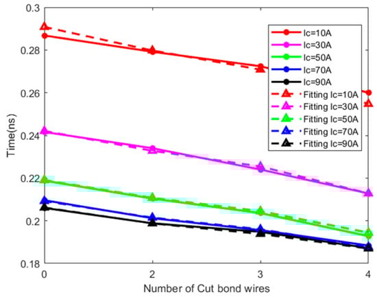
Figure 9.
Comparison between model results and actual results.
By comparing the data generated by the model with the actual data, the error between the two can be clearly and intuitively observed, as shown in Figure 9. The error analysis was carried out for both sets of data using the least squares method, and the resulting fitting R-squared values were all above 0.9, which proves the good accuracy of the model.
3.4. Online Extraction Method for IGBT Turn-Off Time
Assessing the bond wire fatigue of IGBT modules during the normal operation of power electronic converters is a challenging task. As turn-off time can be used as a parameter for evaluating wire bond fatigue, its online extraction method has become critical.
Reference [37] utilized the voltage between the Kelvin terminal and the emitter terminal during the IGBT turn-off process to extract the turn-off delay time. Therefore, this paper uses the Kelvin terminal and Emitter terminal voltages to extract the IGBT turn-off time.
Figure 10 shows the change in VeE between the Kelvin terminal e and the Emitter terminal E in Figure 1b during the turn-off process. The VeE waveform at peak point is caused by the external discharge of the gate capacitor Cge and Miller capacitor Cgc during the turn-off process. This results in a change in the gate current and the generation of voltage due to the inductance on the gate circuit. The VeE waveform at valley point is caused by the change in collector current during the turn-off process, which generates voltage on the bond wire inductance. Thus, the duration of the entire IGBT turn-off process can be represented by the time interval between the peak and valley points of the VeE waveform. This also provides favorable conditions for the subsequent online monitoring of IGBT turn-off time in power electronic converters.
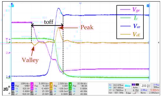
Figure 10.
IGBT turn-off process.
4. Implementation of Online Extraction of IGBT Turn-Off Time
In this section, the triggering and communication functions of an oscilloscope are utilized to acquire IGBT turn-off waveform data in real-time during the operation of a power electronic converter. The online and real-time monitoring of the IGBT module turn-off time is achieved through continuous wavelet transform of the acquired waveform data. The implementation principle of the online monitoring of turn-off time is shown in Figure 11.
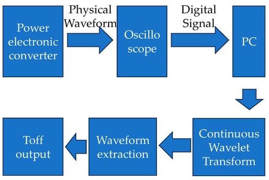
Figure 11.
Schematic diagram of Toff online extraction method implementation.
4.1. Experimental Plan for Online Extraction of Turn-Off Time
Taking IGBT4 in the single-phase reactive power inverter as an example, this study investigates the inverter operating conditions that can provide effective extraction of the turn-off time (Figure 12).
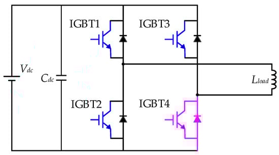
Figure 12.
Topology of single-phase inductor load inverter.
The single-phase inverter adopts the complementary PWM control method for the upper and lower bridge arms, with a switching frequency of 16 kHz and a dead time of 1 us. By analyzing the commutation path of the inductor current in the single-phase inverter, the path of the load current flowing through the IGBT4 switch during the conduction process is shown in Figure 13.
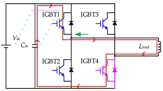
Figure 13.
Operating conditions of single-phase inverter for online monitoring of IGBT4.
Hence, the commutation path of the single-phase inverter that is suitable for online monitoring of the turn-off process of IGBT4. The green arrow in Figure 13 indicates the positive direction of the current probe and the red lines represent one of the commutation paths of the inverter. Therefore, by monitoring the switching status of IGBT4 during the negative half-cycle of the load current in the single-phase inverter, online monitoring of the turn-off time of IGBT4 can be achieved.
4.2. Experimental Results of Online Extraction of Turn-Off Time
By continuously adjusting the triggering settings of the oscilloscope, the waveform data of the Kelvin terminal voltage VeE of a single-phase reactive power inverter during the negative half-cycle of the load current was captured in real-time and transmitted to the toff extraction algorithm, as shown in Figure 14.
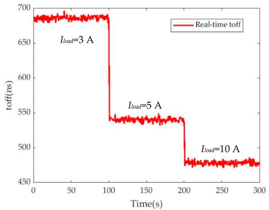
Figure 14.
Online monitoring of IGBT turn-off time.
All of the turn-off time of IGBT4 during half a cycle of load current was obtained, as shown in Figure 15.
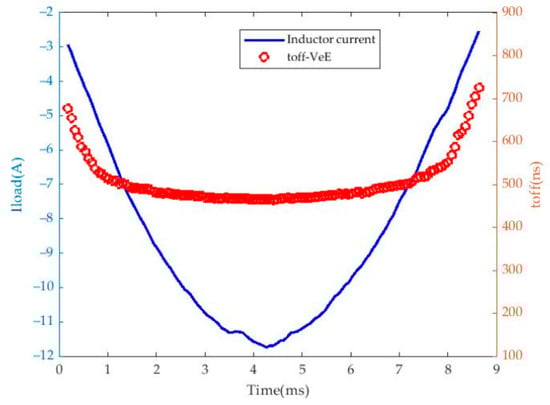
Figure 15.
Trends of load current and IGBT4 turn-off time (toff) vs. time.
In the negative half-cycle of the load current, the turn-off current of IGBT4 is determined by the magnitude of the load current. In other words, changes in the load current will result in changes in the turn-off current of IGBT4. From Figure 8, it can be inferred that the turn-off time will decrease as the turn-off current increases, and the decreasing trend of the turn-off time becomes slower and slower. This can also be observed from Figure 14, where the decreasing trend of the turn-off time becomes flatter as the load current approaches the maximum value in the reverse direction. Therefore, the relationship between the turn-off current (i.e., load current) and turn-off time of IGBT4 is plotted in Figure 16.
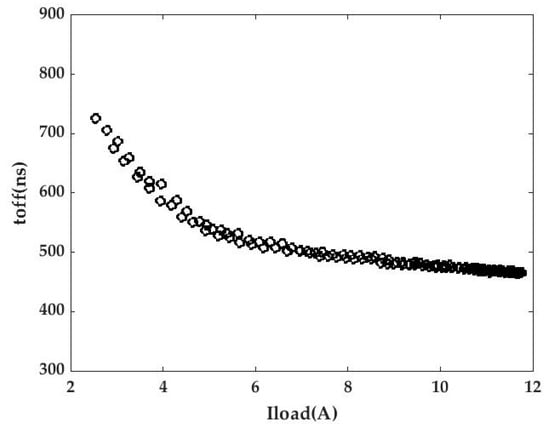
Figure 16.
The relationship between the amplitude of load current and turn-off time of IGBT.
As it is not possible to directly measure the collector current of the IGBT in practical inverters, it is assumed in this study that the turn-off process of the IGBT can be considered complete when the collector–emitter voltage Vce drops from its peak value to the bus voltage Vdc. Therefore, the actual turn-off time of the IGBT can be obtained through the gate voltage Vge and collector–emitter voltage Vce. For this purpose, waveforms of the gate voltage Vge and collector–emitter voltage Vce during the turn-off process of IGBT4 were also simultaneously recorded to determine the actual turn-off time of IGBT4 (Figure 17).
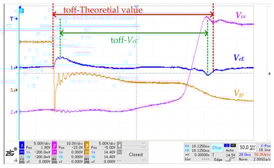
Figure 17.
Theoretical extraction interval of IGBT turn-off time and actual extraction interval based on VeE.
Due to the difference in the extraction interval, Figure 18 shows the difference between the turn-off time extracted based on VeE and the theoretical turn-off time of the IGBT.
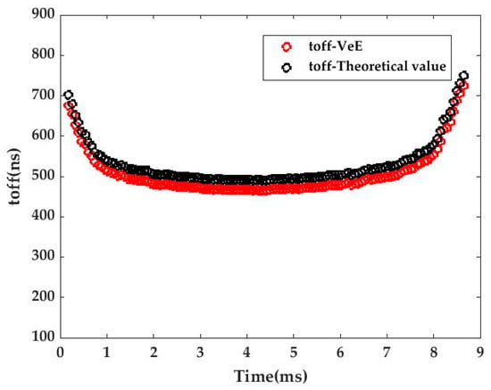
Figure 18.
The relationship between the theoretical turn-off time of IGBT and the extracted value based on VeE.
In theory, the turn-off time extraction method based on VeE should have a fixed proportional relationship with the theoretical turn-off time of the IGBT. In Figure 18, the turn-off time extracted using VeE does indeed have a fixed proportional relationship with the theoretical turn-off time of the IGBT, with a difference of about 25 ns to 30 ns.
4.3. Impact of Other Factors on IGBT Turn-Off Time
The above analysis has discussed the effects of bond wire fatigue and load current variation on turn-off time. However, there are other factors that can also affect the turn-off time, such as the junction temperature and DC bus voltage. Generally speaking, the operating conditions of power electronic converters are in a relatively stable state, and the junction temperature is in a stable state due to the existence of heat dissipation devices. To verify this situation, this study used the real-time monitoring function of the on-state voltage on the experimental platform of the single-phase reactive power inverter to reflect the fluctuation in the junction temperature through the fluctuation of the on-state voltage (Figure 19).
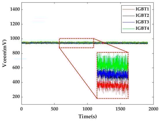
Figure 19.
Trend of IGBT on-state voltage variation in single-phase reactive power inverter.
The single-phase reactive power inverter with a water-cooling machine was set to a temperature of 22 °C, a DC bus voltage of 400 V and a load current of 85 A. It was observed that, during a 1900s operation period, the on-state voltage of the four IGBTs remained very stable throughout the entire process with almost no fluctuations, except for a fixed bias caused by uneven heat dissipation that affected the on-state voltage of the four IGBTs.
Thus, this study assumes that the impact of junction temperature on turn-off time in power electronic converters can be ignored.
5. Conclusions
This study elucidated the feasibility of using turn-off time as a parameter for wire bond fatigue in IGBT modules. A wire bond fatigue assessment model based on turn-off time was constructed for the SRE100N065FSUT1M2 module using an IGBT module dynamic characteristic testing platform. Combined with the experimental platform of the single-phase reactive power inverter, the online extraction of turn-off time was achieved by utilizing the characteristics of the Kelvin terminal voltage VeE during the turn-off process. The accuracy of turn-off time extraction was achieved through the use of signal processing algorithms.
Although the junction temperature can be kept stable during the operation of power electronic converters with the help of water-cooling devices, bond wire fatigue may have already occurred if the inverter’s heat dissipation environment is poor or the heat dissipation conditions are limited, even if the turn-off time does not change. This is because the junction temperature can cause an increase in the IGBT turn-off time. Therefore, a method is still needed to identify both wire bond fatigue and junction temperature to address this situation.
Author Contributions
Methodology, F.W.; Software, H.L.; Validation, H.L., C.S. and W.X. All authors have read and agreed to the published version of the manuscript.
Funding
This research was funded by the National Nature Science Foundations of China, grant number 51977126.
Data Availability Statement
Data openly available in a public repository.
Conflicts of Interest
The authors declare no conflict of interest.
References
- Avenas, Y.; Dupont, L.; Khatir, Z. Temperature Measurement of Power Semiconductor Devices by Thermo-Sensitive Electrical Parameters—A Review. IEEE Trans. Power Electron. 2012, 27, 3081–3092. [Google Scholar] [CrossRef]
- Yang, S.; Xiang, D.; Bryant, A.; Mawby, P.; Ran, L.; Tavner, P. Condition Monitoring for Device Reliability in Power Electronic Converters: A Review. IEEE Trans. Power Electron. 2010, 25, 2734–2752. [Google Scholar] [CrossRef]
- Wu, W.; Held, M.; Jacob, P.; Scacco, P.; Birolini, A. Investigation on the long term reliability of power IGBT modules. In Proceedings of the International Symposium on Power Semiconductor Devices and IC’s: ISPSD ’95, Yokohama, Japan, 23–25 May 1995. [Google Scholar]
- Wang, H.; Liserre, M.; Blaabjerg, F.; de Place Rimmen, P.; Jacobsen, J.B.; Kvisgaard, T.; Landkildehus, J. Transitioning to Physics-of-Failure as a Reliability Driver in Power Electronics. IEEE J. Emerg. Sel. Top. Power Electron. 2014, 2, 97–114. [Google Scholar] [CrossRef]
- Wang, H.; Liserre, M.; Blaabjerg, F. Toward Reliable Power Electronics: Challenges, Design Tools, and Opportunities. IEEE Ind. Electron. Mag. 2013, 7, 17–26. [Google Scholar] [CrossRef]
- Wang, C.L.; Zheng, L.B.; Fang, H.C.; Han, L. Analysis of the performance effect with bonding wires lift-off in IGBT modules. Trans. China Electrotech. Soc. 2014, 29, 184–191. [Google Scholar]
- Choi, U.; Blaabjerg, F.; Lee, K. Study and Handling Methods of Power IGBT Module Failures in Power Electronic Converter Systems. IEEE Trans. Power Electron. 2015, 30, 2517–2533. [Google Scholar] [CrossRef]
- Ciappa, M. Selected failure mechanisms of modern power modules. Microelectron. Reliab. 2002, 42, 653–667. [Google Scholar] [CrossRef]
- Fu, H.; Li, Y.; Li, Q.; Tu, C.; Xiao, B.; Xiao, F.; Liu, P.; Gao, B.; Lu, J. Failure Mechanism Analysis of Bond Wire of High Power IGBT under Different Load Current. In Proceedings of the 2022 IEEE 5th International Electrical and Energy Conference (CIEEC), Nanjing, China, 27–29 May 2022; pp. 798–803. [Google Scholar]
- Smet, V.; Forest, F.; Huselstein, J.; Richardeau, F.; Khatir, Z.; Lefebvre, S.; Berkani, M. Ageing and Failure Modes of IGBT Modules in High-Temperature Power Cycling. IEEE Trans. Ind. Electron. 2011, 58, 4931–4941. [Google Scholar] [CrossRef]
- Yang, L.; Agyakwa, P.A.; Johnson, C.M. Physics-of-Failure Lifetime Prediction Models for Wire Bond Interconnects in Power Electronic Modules. IEEE Trans. Device Mater. Reliab. 2013, 13, 9–17. [Google Scholar] [CrossRef]
- Yang, L.; Agyakwa, P.A.; Johnson, C.M. A time-domain physics-of-failure model for the lifetime prediction of wire bond interconnects. Microelectron. Reliab. 2011, 51, 1882–1886. [Google Scholar] [CrossRef]
- Du, M.; Wei, K.; Li, J.; Xie, L. Condition monitoring IGBT module bond wire lift-off using measurable signals. In Proceedings of the 7th International Power Electronics and Motion Control Conference, Harbin, China, 2–5 June 2012; pp. 1492–1496. [Google Scholar]
- Wei, K.; Du, M.; Xie, L.; Li, J. Study of Bonding Wire Failure Effects on External Measurable Signals of IGBT Module. IEEE Trans. Device Mater. Reliab. 2014, 14, 83–89. [Google Scholar] [CrossRef]
- Hanif, A.; Devoto, D.; Khan, F. Bond Wire Damage Detection and SOH Estimation of a Dual-Pack IGBT Power Module Using Active Power Cycling and Reflectometry. IEEE Trans. Power Electron. 2020, 35, 6761–6772. [Google Scholar] [CrossRef]
- Das, S.; Khan, F.; Alam, M.K.; Goli, P. Detection of Aging Related IGBT Bond-wire Lift-off Using Spread Spectrum Time Domain Reflectometry (SSTDR). In Proceedings of the 2017 IEEE Applied Power Electronics Conference and Exposition (APEC), Tampa, FL, USA, 26–30 March 2017. [Google Scholar]
- Hanif, A.; Khan, F. Degradation Detection of Thermally Aged SiC and Si Power MOSFETs using Spread Spectrum Time Domain Reflectometry (SSTDR). In Proceedings of the 2018 IEEE 6th Workshop on Wide Bandgap Power Devices and Applications (WiPDA), Atlanta, GA, USA, 31 October–2 November 2018; pp. 18–23. [Google Scholar]
- Hanif, A.; Das, S.; Khan, F. Active Power Cycling and Condition Monitoring of IGBT Power Modules using Reflectometry. In Proceedings of the 2018 IEEE Applied Power Electronics Conference and Exposition (APEC), San Antonio, TX, USA, 4–8 March 2018. [Google Scholar]
- Hanif, A.; Azad, A.N.M.W.; Khan, F. Detection of Bond Wire Lift Off in IGBT Power Modules Using Ultrasound Resonators. In Proceedings of the 2020 IEEE Applied Power Electronics Conference and Exposition (APEC), New Orleans, LA, USA, 15–19 March 2020. [Google Scholar]
- Hanif, A.; Major, J.; Devoto, D.; Khan, F. Bond Wire Damage Detection and State of Health Estimation of a 1200V, 900A Dual Pack IGBT Power Module using the RL-Equivalent Circuit. In Proceedings of the 2019 IEEE Applied Power Electronics Conference and Exposition (APEC), Anaheim, CA, USA, 17–21 March 2019. [Google Scholar]
- Zhou, S.; Zhou, L.; Sun, P. Monitoring Potential Defects in an IGBT Module Based on Dynamic Changes of the Gate Current. IEEE Trans. Power Electron. 2013, 28, 1479–1487. [Google Scholar] [CrossRef]
- Wang, K.; Zhou, L.; Sun, P.; Du, X. Monitoring Bond Wires Fatigue of Multichip IGBT Module Using Time Duration of the Gate Charge. IEEE Trans. Power Electron. 2021, 36, 888–897. [Google Scholar] [CrossRef]
- Yang, Y.; Zhang, P. A Novel Bond Wire Fault Detection Method for IGBT Modules Based on Turn-on Gate Voltage Overshoot. IEEE Trans. Power Electron. 2021, 36, 7501–7512. [Google Scholar] [CrossRef]
- Jing, L.; Du, M.; Wei, K.; Hurley, W.G. A Health Monitoring Method for Bond Wires in IGBT Modules Based on Voltage Ringing Characteristics. IEEE Trans. Electron Devices 2019, 66, 3953–3960. [Google Scholar] [CrossRef]
- Peng, Y.; Sun, P.; Zhou, L.; Du, X.; Cai, J. A Temperature-Independent Method for Monitoring the Degradation of Bond Wires in IGBT Modules based on Transfer Characteristics. In Proceedings of the 2017 IEEE Applied Power Electronics Conference and Exposition (APEC), Tampa, FL, USA, 26–30 March 2017. [Google Scholar]
- Zhang, W.; Tan, K.; Ji, B.; Qi, L.; Cui, X.; Zhang, X.; Du, L. In Situ Diagnosis of Multichip IGBT Module Wire Bonding Faults Based on Collector Voltage Undershoot. IEEE Trans. Ind. Electron. 2023, 70, 3045–3054. [Google Scholar] [CrossRef]
- Eleffendi, M.A.; Johnson, C.M. In-Service Diagnostics for Wire-Bond Lift-off and Solder Fatigue of Power Semiconductor Packages. IEEE Trans. Power Electron. 2017, 32, 7187–7198. [Google Scholar] [CrossRef]
- Li, Y.; Zhou, L.; Sun, P.; Peng, Y.; Cai, J. Condition Monitoring for IGBT Module Aging Failure on VCE(on) under Certain IC Conditions. Trans. China Electrotech. Soc. 2018, 33, 3202–3212. [Google Scholar] [CrossRef]
- Singh, A.; Anurag, A.; Anand, S. Evaluation of Vce at Inflection Point for Monitoring Bond Wire Degradation in Discrete Packaged IGBTs. IEEE Trans. Power Electron. 2017, 32, 2481–2484. [Google Scholar] [CrossRef]
- Smet, V.; Forest, F.; Huselstein, J.; Rashed, A.; Richardeau, F. Evaluation of Vce Monitoring as a Real-Time Method to Estimate Aging of Bond Wire-IGBT Modules Stressed by Power Cycling. IEEE Trans. Ind. Electron. 2013, 60, 2760–2770. [Google Scholar] [CrossRef]
- Wang, X.; Sun, P.; Sun, L.; Luo, Q.; Du, X. Online Condition Monitoring for Bond Wire Degradation of IGBT Modules in Three-Level Neutral-Point-Clamped Converters. IEEE Trans. Ind. Electron. 2021, 68, 7474–7484. [Google Scholar] [CrossRef]
- Wang, C.; He, Y.; Jiang, Y.; Li, L. An Anti-Interference Online Monitoring Method for IGBT Bond Wire Aging. Electronics 2021, 10, 1449. [Google Scholar] [CrossRef]
- Hu, Z.; Ge, X.; Xie, D.; Zhang, Y.; Yao, B.; Dai, J.; Yang, F. An Aging-Degree Evaluation Method for IGBT Bond Wire with Online Multivariate Monitoring. Energies 2019, 12, 3962. [Google Scholar] [CrossRef]
- Liu, S.; Tu, C.; Long, L.; Xu, H.; Xiao, B.; Zhu, Z. A Method Monitoring Healthy State of Bond Wires in IGBT Based on dVCE/diC. In Proceedings of the IECON 2022—48th Annual Conference of the IEEE Industrial Electronics Society, Brussels, Belgium, 17–20 October 2022. [Google Scholar]
- Luo, D.; Chen, M.; Lai, W.; Xia, H.; Deng, Z.; Wang, Z.; Yu, K. A Fault Detection Method of IGBT Bond Wire Fatigue Based on the Reduction of Measured Heatsink Thermal Resistance. Electronics 2022, 11, 1021. [Google Scholar] [CrossRef]
- Du, M.; Tang, Y.; Gao, M.; Ouyang, Z.; Wei, K.; Hurley, W.G. Online Estimation of the Junction Temperature Based on the Gate Pre-Threshold Voltage in High-Power IGBT Modules. IEEE Trans. Device Mater. Reliab. 2019, 19, 501–508. [Google Scholar] [CrossRef]
- Luo, H.; Chen, Y.; Sun, P.; Li, W.; He, X. Junction Temperature Extraction Approach with Turn-off Delay Time for High-voltage High-Power IGBT Modules. IEEE Trans. Power Electron. 2016, 1, 5122–5132. [Google Scholar] [CrossRef]
- Sun, P.; Luo, H.; Dong, Y.; Li, W.; He, X. Junction Temperature Extraction of High Power IGBT Module Based on Turn-off Delay Time. Proc. CSEE 2015, 35, 3366–3372. [Google Scholar] [CrossRef]
- Chen, Y.; Luo, H.; Li, W.; He, X.; Iannuzzo, F.; Blaabjerg, F. Analytical and Experimental Investigation on A Dynamic Thermo-Sensitive Electrical Parameter with Maximum di/dt During Turn-off for High Power Trench Gate/Field-Stop IGBT Modules. IEEE Trans. Power Electron. 2017, 32, 6394–6404. [Google Scholar] [CrossRef]
Disclaimer/Publisher’s Note: The statements, opinions and data contained in all publications are solely those of the individual author(s) and contributor(s) and not of MDPI and/or the editor(s). MDPI and/or the editor(s) disclaim responsibility for any injury to people or property resulting from any ideas, methods, instructions or products referred to in the content. |
© 2023 by the authors. Licensee MDPI, Basel, Switzerland. This article is an open access article distributed under the terms and conditions of the Creative Commons Attribution (CC BY) license (https://creativecommons.org/licenses/by/4.0/).