Abstract
In light of the predicament concerning the small gain and narrow frequency range of miniature antennas, this paper employs the implementation of a fractal repeating array structure and a double-layer folding antenna structure. Through these measures, the miniature antenna is endowed with a high gain and an expansive frequency range, all within its diminutive size. The paper presents an exquisite and high-gain flexible multi-band antenna, utilizing a dielectric substrate composed of the flexible material polyimide, with a thickness of merely 0.1 mm. The implementation of this flexible material bestows a feathery mass of merely 4 mg upon the antenna, enabling it to seamlessly conform to various shapes. This makes it particularly well-suited for employment within miniature wireless transmission systems and compact mobile communication devices. In an endeavor to enhance impedance matching and radiation characteristics, the Minkowski fractal structure is ingeniously incorporated as the repeating array element. This repeating array structure assumes a pivotal role and, when combined with the double-layer folding antenna structure, achieves the objective of miniaturization. Remarkably, the antenna’s dimensions measure a mere 0.04 λ0 × 0.026 λ0 (λ0 @ 2.4 GHz). The proposed antenna boasts a remarkably diminutive volume of merely 5 × 3 × 0.1 mm3, with the measured and simulated results exhibiting a striking concurrence. Both sets of results demonstrate resonance across multiple frequencies, namely, 2.4 GHz, 5.2 GHz and 5.8 GHz. Furthermore, within the effective frequency range, the antenna attains a maximum gain of 1.65 dBi and 4.37 dBi, respectively.
1. Introduction
Presently, miniature wireless transmission systems assume an exceedingly significant role in the realms of mobile communications, medical applications and security monitoring. The burgeoning trend of interconnecting multiple devices has emerged as the prevailing wave in miniature wireless transmission system applications [1]. Consequently, this necessitates the elevation of standards pertaining to the integration of antennas within mobile wireless transmission systems, entailing increasingly exacting communication requirements. These requirements encompass dimensions such as compact size, feather-like weight, impeccable radiation characteristics and steadfast impedance matching. Furthermore, it is imperative that the design of antennas adheres to the fundamental limits imposed by the laws of physics, rendering the creation of miniature multi-band antennas the most formidable aspect of the communication unit.
Miniaturized antennas offer a pathway towards the realization of microsystems and portable equipment, while the inclusion of multi-band capabilities renders devices well-suited for diverse and heterogeneous environments. As the advent of 5 G technology unfolds, the significance of miniaturization and multi-band attributes in future miniature wireless transmission systems intensifies. Among the primary challenges confronting miniaturized antennas lies the delicate balance between vital performance metrics such as antenna size and antenna gain. Nevertheless, judicious structural design holds the potential to achieve heightened gain [2]. Consequently, novel antenna architectures pave the way for the realization of high-performance, multi-band miniaturized antennas, poised to meet the burgeoning communication demands of miniature wireless transmission systems.
Therefore, in order to design multi-band and high-performance miniaturized antennas, various antenna designs have been proposed, which are based on special structural patches, fractal structures and special materials [3], and many researchers are committed to the study of micro-multi-band antennas. Firstly, the special patch structure can be used to excite the high resonance mode of the antenna to achieve multi-band and antenna miniaturization. Abolade [4] explored an open B-bend patch to design dual-band antennas operating at 1.85 GHz and 5.89 GHz with bandwidths of 179 MHz and 2290 MHz and an antenna dielectric substrate size of 19 × 12 mm2. Similarly, Zhang [5] proposed an open ring patch structure and designed a reasonable ground plane to achieve 2.4 GHz, 5.2 GHz and 5.8 GHz multi-band resonance, bandwidth of 80 MHz and 3410 MHz, and an antenna dielectric substrate size of 25 × 20 mm2, of which the 2.4 GHz band is narrow. The 2.4 GHz communication band stipulated by ISM cannot be fully covered. Hammoodi [6] proposed a simplified linear structure of tri-band antennas to achieve 2.45 GHz, 3.5 GHz and 5 GHz bands with bandwidths of 220 MHz, 440 MHz and 140 MHz, but the antenna size in the paper is large with a dielectric size of 75 × 75 mm2. Secondly, the Minkowski fractal structure is also an effective structure for achieving antenna miniaturization. Nornikman [7] uses a planar Minkowski fractal structure and diamond-shaped SRR design to achieve 2.4 GHz and 5.5 GHz dual bands with bandwidths of 80 MHz and 229 MHz and a dielectric substrate size of 30 × 28 mm2. Mokhtari [8] proposed a tree-shaped Minkowski fractal structure that reduces the antenna size to 0.0471 λ02, in which the antenna resonant center frequency is 4.48 GHz, the bandwidth is 1560 MHz and the dielectric substrate size is 16 × 13.2 mm2. Thirdly, the flexible antenna, with its minimal thickness, light mass, small volume and easy bending, has significance in the process of antenna miniaturization research significance [9,10] and a broader market development prospect [11,12]. Samal [13] designed a 5.8 GHz antenna with a bandwidth of 130 MHz on a small cross-sectional area and low-loss flexible cable material, combined with slotting techniques, with a dielectric substrate size of 25 × 25 mm2 and a high gain of 6.9 dBi, but there is still room for further optimization of the bandwidth in the paper. Zaidi [14] proposed a reconfigurable small antenna based on a flexible substrate with an overall antenna size of 25 × 25 × 0.245 mm3 and operating bands of 2.5 GHz, 5.5 GH and 6.8 GHz, which can be applied in small communication devices due to its thin and light material. Common flexible substrates such as foam, denim, felt, etc. are used in [15] to design high-gain wearable flexible antennas with special shapes or array structures that are lightweight and can reduce costs. It should be noted that the size of most multi-band miniaturized antennas in the literature is still large, and the working frequency is a narrower band. Although the size of most of these antennas has been less than 0.25 λ0, there is still room for miniaturization in the miniature wireless transmission system. In addition, antennas with more operating bands and wider bandwidths can be used for a wider range of applications simultaneously.
In this study, a flexible dual-band antenna with ultra-small size is proposed. The antenna design adopts the Minkowski fractal structure as the repeating array, which is arranged systematically in turn. In combination with folding technology, the antenna branches are folded and placed on the upper and lower sides of the dielectric substrate to effectively reduce the antenna size. The overall size of the flexible antenna is only 5 × 3 × 0.1 mm3, and the dielectric material adopts a polyimide substrate whose thickness is only 0.1 mm. The antenna can work in the 2.4 GHz/5.2 GHz/5.8 GHz frequency band, and the effective bandwidth exceeds 100 MHz and 1300 MHz. The antenna in this research has a relatively high gain while being small in size. The highest gain in the 2.4 GHz frequency band is 1.65 dBi, and the highest gain in the 5 GHz frequency band is 4.37 dBi. It has strong practicability and wide range of applications.
2. Materials and Methods
2.1. Antenna Design
The design presented in this study revolves around the integration of both the folding structure and the Minkowski fractal structure. Notably, the Minkowski fractal structure emerges from the iterative addition and scaling of regular triangular, square or circular geometries within the plane or space [16,17,18,19]. This intricate structure possesses remarkable attributes of self-similarity, complexity and fractal dimension, enabling the reconfiguration of both the size and performance of the antenna. Consequently, leveraging Minkowski fractal structures in the design of multi-band and miniaturized antennas offers substantial advantages and unrivaled potential.
Figure 1d shows a comparison between the square ring and the first-order and second-order fractal rings. It is noteworthy that all three antenna structures exhibit resonance at the same frequency. It is clear from the figure that the size of the second-order fractal ring is substantially reduced compared to the first-order fractal ring, which is 36% smaller than the square ring. Importantly, there is no significant difference in the radiation characteristics, impedance matching and orientation diagrams of these three antenna structures. The use of folding techniques in antenna design represents a specialized technique called radiating patch technique [20,21]. This design method increases the effective electrical length of the antenna by changing the current path on the antenna surface, thus reducing the resonant frequency point. In this research, we use a deformable structure based on a first-order Minkowski fractal antenna and combine it with the folding technique to introduce a novel structure—a compact antenna with multi-band capabilities and high gain.
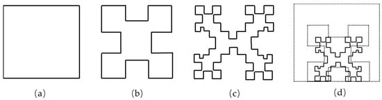
Figure 1.
Fractal ring iteration steps and size comparison. (a) Rectangular ring structure; (b) First-order fractal ring structure; (c) Second-order fractal ring structure; (d) Dimensional comparison of Minkowski fractal ring and square ring.
Figure 2 depicts the design of the novel antenna structure based on the first-order Minkowski fractal structure proposed in this study. The antenna is implemented on a flexible polyimide dielectric substrate with a total thickness of 0.1 mm. The dielectric material possesses a dielectric constant (εr) of 3.5 and a dielectric loss (δ) of 0.008. In the double-layer antenna design, the folding technique is employed to configure the antenna branches on both the front and back sides of the substrate. The size of the antenna branches in this study is λ/4, ensuring optimal performance. On the front side of the antenna, half of the first-order Minkowski’s deformed structure is employed as the unit array. Three identical unit arrays are arranged, satisfying both axial symmetry and center symmetry requirements. The total length of the branches amounts to 27.78 mm. On the rear side of the antenna, the branches are curved in a gate-shaped structure, enabling an extension of the antenna branch length. As a result, the final dimensions of the antenna are 5 × 3 × 0.1 mm3.
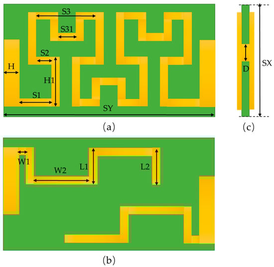
Figure 2.
Antenna structure diagram. (a) Antenna front branching part; (b) Antenna side part; (c) Antenna back branching part.
Table 1 provides a summary of the antenna dimension parameters in this study, including SX, SY, SUBH, H, S1, W2, L2, H1, S2, S3, S31, W1, L1 and D, which are consistent with the description in Figure 2. These parameters are all parameters of the antenna design, but the labeling of the same parameters is omitted; for example, the size of the branch on the lower side of the back of the antenna is the same as the size of the upper side, so they are not labeled in Figure 2 and Table 1. The above antenna parameters are the optimal solutions obtained by structural design and parameter scanning, and the specific dimensions are shown in Table 1.

Table 1.
Antenna parameters of this study.
In order to further understand the radiation mechanism of the antenna, the following material will briefly describe the antenna design method. The simulation tool used in the antenna design in this study is 2020 Ansys HFSS 3D high-frequency simulation software. Figure 3 illustrates the progressive stages of the antenna design process. The initial design centers around the compact arrangement of the first-order Minkowski fractal array structure, aiming to minimize the overall size without compromising the desired radiation characteristics. This unique structure inherently enables the realization of multi-band antennas. By strategically bending the antenna array structure, additional frequency bands can be excited, thereby expanding the antenna’s operational range. Furthermore, the electromagnetic interaction among the branches facilitates the generation of enhanced radiation currents, ultimately elevating the antenna’s gain.
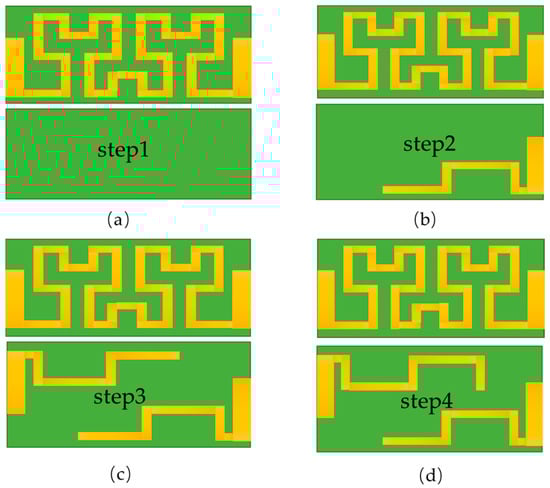
Figure 3.
Antenna design steps. (a) The first step of the design steps; (b) The second step of the design steps; (c) The third step of the design steps; (d) The fourth step of the design steps.
Initially, in the front portion of the dielectric substrate, a three-unit array is crafted as a foundational patch. This choice is made due to the high-performance attributes exhibited by the aforementioned antenna structure. Subsequently, in the second step, the folding antenna structure is introduced, incorporating an additional section of branches on the rear side of the antenna. Building upon the advancements made in the second step, the third step involves further augmentation of the antenna by adding another section of branches to the rear side. Lastly, a 1 mm long branch is appended to fine-tune the frequency band characteristics.
The rectangular basic radiation element length of fc with a given frequency is calculated by the following formula, where L is the antenna branch length, and then the medium substrate length SY [22] is determined by L.
This expression can be simplified as [23]:
where εe is the effective dielectric constant of the dielectric surface, the antenna in this study is a monopole antenna, the effective dielectric constant εe is determined by the surrounding air layer (ε0 = 1) and the dielectric constant εr of the dielectric substrate, fc is the operating frequency of the antenna and c is the velocity of the wavelength in vacuum (c = 3 × 10⁸ m/s).
In order to calculate the effective dielectric constant εe, the width SX of the patch should be determined. Due to the dense structure of the patch in this research, SX can be considered as the width of the dielectric substrate.
The approximate expression of the effective dielectric constant is as follows [24]:
where εr is the dielectric constant of the dielectric substrate and h is the thickness of the dielectric substrate.
Using the aforementioned equation, the length of the antenna branches (L) is calculated within the range of 30–40 mm. The length of the dielectric substrate (SY) is determined to be 5 mm, while the width is set to SX = 3 mm. Figure 4 presents a comprehensive diagram illustrating the different stages of the antenna structure and their corresponding return loss curves. In Figure 3a, the first step demonstrates the antenna structure’s multi-band characteristics. By incorporating the folding antenna technique in the design during the second step (Figure 3b), the effective antenna band is shifted to the left, expanding the absolute bandwidth of the high band by 880 MHz. Figure 3c represents the third step, where a center symmetric structure is adopted for the design at the rear. This further expands the bandwidth of the high-frequency band, allowing full coverage of the communication frequency band of 5.2 GHz/5.8 GHz (5.15–5.85 GHz). The complete bandwidth of the 5 GHz band is 1310 MHz, with a minimum return loss value of −31 dB. Lastly, the fourth step in Figure 3d involves adding 1 mm to adjust the frequency band branches, ensuring complete coverage of the 2.4 GHz (2.4–2.48 GHz) communication band in the low-frequency range.
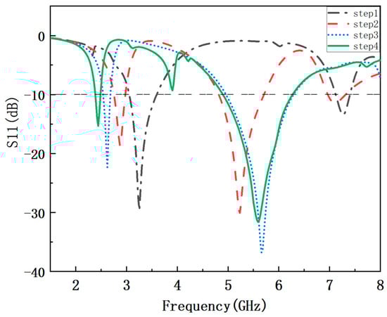
Figure 4.
S11 curve in the antenna design step.
2.2. Methods of Antenna Measurement
The physical characteristics of the antenna were measured experimentally and the reflection coefficient of the antenna was measured by a vector network analyzer on a PCB board with the antenna soldered on, as shown in Figure 5a. The radiation pattern of the antenna was obtained in the microwave far-field region. To perform this measurement, the antenna system was positioned in the far field of a transmitting antenna and placed on a turntable that allowed for free rotation, as shown in Figure 5b. This setup enabled the proposed antenna to be illuminated by the transmitting antenna from various angles, providing a comprehensive assessment of its radiation properties.
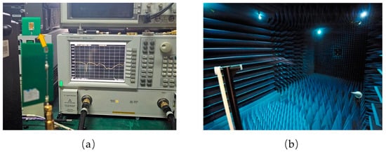
Figure 5.
Antenna test apparatus. (a) Vector network analyzer; (b) Microwave far-field darkroom.
3. Results and Discussion
3.1. Antenna Surface Current Analysis
Figure 6 presents the surface current distribution of the antenna proposed in this article, providing a visual and convenient means to examine the excitation mechanism of the dual-band antenna. Analysis of the figure reveals that, at 2.44 GHz, the surface current of the miniature antenna primarily flows through the Minkowski structure branches on the front side of the antenna and the antenna branches on the top and bottom sides of the back. This indicates that the overall branches of the antenna serve as effective paths for current at 2.44 GHz. On the other hand, at 5.6 GHz, the surface current of the miniature antenna is primarily concentrated in the bent branches on the lower side of the back, with the edge of the middle branch on the front side also contributing slightly to the excitation of the surface current. This suggests that the lower branch on the back provides an effective current path in the resonant mode at 5.6 GHz. Consequently, this design is capable of generating multiple effective working frequency bands simultaneously. The patch current distribution diagram further validates the process of setting the corresponding antenna frequency bands in the antenna design. In the second step of the design, antenna branches are added to the lower side of the back, leading to the appearance of the corresponding frequency band near 5 GHz. In the third step of the design, antenna branches are added to the upper side of the back, causing the low-frequency band to shift to the left, bringing it much closer to the 2.4 GHz band.
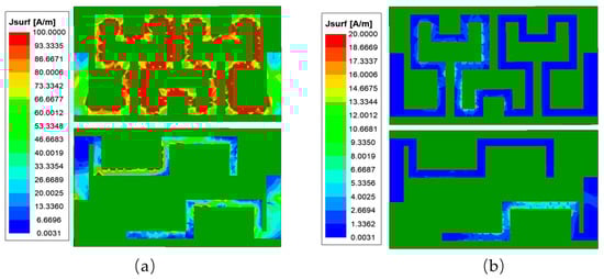
Figure 6.
Antenna surface current excitation diagram. (a) Antenna surface current excitation diagram at 2.44 GHz; (b) Antenna surface current excitation diagram at 5.6 GHz.
3.2. Parametric Study
The final parameter values of the antenna are determined by a combination of theoretical calculations and parameter scan optimization to find the optimal solution. The size of the frontal antenna branches is designed to maximize the utilization of the dielectric substrate. The frontal design of the antenna in this study demonstrates two frequency bands, while the back design enables the antenna to cover the target frequency band. The design challenge in this study for the miniature antenna is to cover the 5.2 GHz/5.8 GHz band while meeting the 2.4 GHz band, which is difficult to achieve. The ideal band is obtained by scanning key parameters, and Figure 6, which shows the antenna surface current excitation diagram, is used to determine the three parameters (W1, W2 and L2) that influence the antenna’s performance at the 2.4 GHz band. These parameters are further studied to match the antenna impedance and investigate the influence of antenna size on resonance, as depicted in the figure below.
Figure 7 is a parameter scan of the parameter W2, where the scan range is 1.4–1.55 mm, the scan step is 0.5 mm and the branch W2 on the 2.4 GHz band becomes larger as the operating frequency becomes lower. When W2 = 1.45 mm, it can cover more of the 2.4 GHz band, so the parameter W2 is determined as 1.45 mm.
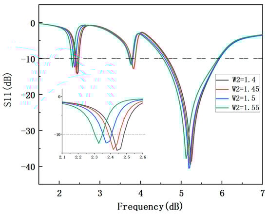
Figure 7.
Comparison chart of scan S11 with parameter W2.
Figure 8 determines that W1 = 1.45 mm. In the parameter scan of W1, the scan range is 0.1–0.4 mm and the influence of parameter W1 on the 2.4 GHz band becomes larger as the frequency becomes lower. Even a small increase in W1 can have a greater impact on the 2.4 GHz band. When W1 = 0.1 mm, it can cover more of the 2.4 GHz band, so this determines that W1 = 0.1 mm.
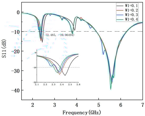
Figure 8.
Comparison chart of scan S11 with parameter W1.
Figure 9 illustrates the parameter scanning of L2, which represents the branch length for frequency regulation, ranging from 0.6 mm to 1.4 mm. The comparison of S11 (return loss) with different values of L2 reveals that L2 has minimal impact on the high-frequency band. However, it does affect the low-frequency band as follows: the larger the value of L2, the lower the frequency band. When L2 is set to 1 mm, the 2.4 GHz frequency band can be completely covered. Based on the parameter scan optimization, the key parameters of the antenna are determined as W2 = 1.45 mm, W1 = 0.1 mm and L2 = 1 mm.
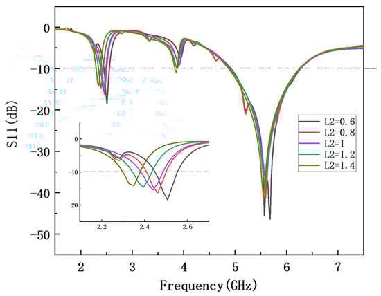
Figure 9.
Comparison chart of scan S11 with parameter L2.
3.3. Antenna Preparation and Characterization
To validate the simulated antenna model, a prototype of the proposed multi-band antenna is fabricated, as depicted in Figure 10, the physical properties of the antenna are shown in Table 2. The antenna’s maximum size does not exceed 5 mm. FPC (flexible printed circuit board) technology is employed to fabricate the antenna structure, and the dielectric material used is polyimide with a dielectric constant (εr) of 3.5 and a loss angle tangent (δ) of 0.008. Due to the small size of the antenna and the close spacing of the branches, a layer of protective oil is applied to the antenna’s exterior to prevent short circuits and friction between the branches that could damage its performance.
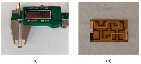
Figure 10.
Antenna physical structure and actual size. (a) Dimensional measurement drawing of the physical antenna; (b) Physical antenna.
Table 2.
Antenna physical properties.
3.4. Measurement of Antenna
Figure 11 presents a comparison between the simulated and measured reflection coefficients of the proposed flexible dual-band antenna based on the Minkowski fractal structure. The measurement results demonstrate that the antenna achieves a reflection coefficient below −10 dB within the measured bandwidth |S11|, which spans from 2.38 to 2.48 GHz and 4.9 to 6.27 GHz. Table 3 provides a comparison between the simulated and measured gain of the antenna, as well as the antenna simulation efficiency. It can be observed that the measured results yield a high gain of 1.65 dBi in the 2.4 GHz band and 4.37 dBi in the 5 GHz band. These measurements indicate that the antenna in this study achieves high gain at a similar or comparable size. When comparing the simulation and measurement results, it is evident that the 2.4 GHz band remains nearly the same, while the measured 5 GHz band slightly shifts towards higher frequencies. Additionally, the realized gain in the 2.4 GHz band decreases from 1.77 dBi (simulation) to 1.65 dBi (measurement), while the gain in the 5 GHz band increases from 3.8 dBi (simulation) to 4.37 dBi (measurement). These small discrepancies in the results may be attributed to factors such as printing issues during antenna fabrication, the presence of protective cover oil on the antenna surface or variations in the measured dielectric properties [25].
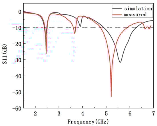
Figure 11.
Comparison of S11 curves between simulation stage and actual measurement stage.
Table 3.
The maximum gain and radiation efficiency of the antenna.
Figure 12 shows the 3D radiation pattern of the simulation stage. Figure 13 illustrates the simulated and measured E-plane and H-plane radiation pattern of the proposed flexible dual-band antenna based on the Minkowski fractal structure. The radiation pattern is selected to visualize the antenna’s behavior at 2.45 GHz and 5.2 GHz. At 2.45 GHz, the measured directional pattern closely aligns with the simulation results. In the radiation pattern, the E-plane exhibits a closer-to-omnidirectional pattern and the directional curve appears smoother with fewer abrupt changes. The H-plane demonstrates better radiation characteristics at 0° and 180°. Similarly, at 5.2 GHz, the E-plane displays improved omnidirectionality, while the H-plane maintains better radiation characteristics at 0° and 180°. To ensure smoother graphics, continuity in the displayed results and ease of interpretation, any anomalies that may arise from connections and stacking are eliminated during the plotting process.
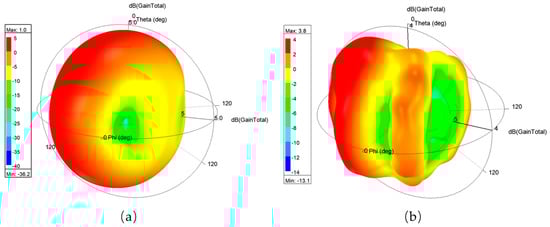
Figure 12.
Simulated 3D radiation pattern. (a) Simulated 3D radiation pattern at 2.45 GHz (b) Simulated 3D radiation pattern at 5.2 GHz.
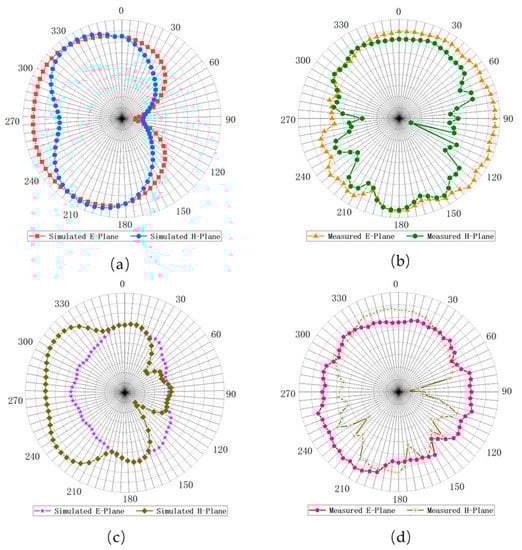
Figure 13.
Antenna EH plane pattern. (a) Simulated pattern at 2.45 GHz (b) Measured pattern at 2.45 GHz (c) Simulated pattern at 5.2 GHz (d) Measured pattern at 5.2 GHz.
Figure 14 shows that when the flexible antenna of this study is connected to the camera communication equipment, the camera can receive the picture and sound normally, and the effective transmission distance of the signal is more than 60 m. Figure 14b shows that if the camera equipment of the flexible antenna is conformal with the surface, then the video signal transmission distance can still reach 60 m. It is easy for the antenna in this research to be conformal with the surface and performance is not affected.
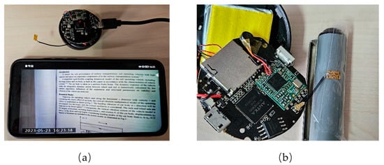
Figure 14.
Antenna physical performance verification diagram. (a) Flexible antenna for camera device; (b) Flexible antenna placed on the curved surface for camera device.
The S11 curve and radiation pattern of the bent antenna and the original antenna are compared in the simulation experiment under the bent state. The S11 curve of the curved antenna is shifted to the right to fully cover the 5.2 GHz and 5.8 GHz bands. The radiation pattern of the curved antenna is basically consistent with that of the original antenna (see Supplementary Materials).
The study also conducted simulations with the addition of obstacles, the results of which are shown in the Supplementary Materials (see Supplementary Materials).
Table 4 provides a performance comparison between the antenna proposed in this study and existing small-size antennas. The comparison demonstrates that the flexible multi-band antenna designed in this study has the ability to fully cover the frequency bands of 2.4 GHz, 5.2 GHz and 5.8 GHz, offering wider bandwidth, higher gain, efficiency and a smaller physical size compared to the current alternatives.
Table 4.
Comparison of the antenna performance in this study with that in the references.
4. Conclusions
This study introduces a novel antenna structure based on the combination of a folded structure and a first-order Minkowski fractal structure. The unique patch design effectively reduces the antenna’s size while maintaining its multi-band capability and high-gain performance. The resulting antenna has an extremely compact size of 0.04λ0 × 0.026λ0 (λ0 @ 2.4 GHz), making it suitable for operation in the 2.4 GHz/5.2 GHz/5.8 GHz frequency bands. The antenna achieves a maximum gain of 1.65 dBi in the low band and 4.37 dBi in the high band. Additionally, the use of a flexible substrate allows for a thin, lightweight and bendable antenna, making it suitable for various micro wireless transmission systems. The antenna’s performance is validated through testing with a camera device, demonstrating an effective transmission distance of over 60 m. The antenna maintains its signal propagation capabilities even in a curved and conformal state. These findings establish a strong foundation for the antenna’s application in microsystems, biomedical devices, small mobile communication devices and other relevant fields.
Supplementary Materials
The following supporting information can be downloaded at: https://www.mdpi.com/article/10.3390/electronics12143059/s1, Figure S1: Antenna bending model; Figure S2: Bending antenna and original antenna of S11 comparison; Figure S3: Comparison of the radiation pattern of the bent antenna and the original antenna; Figure S4: Comparison of antenna models before and after adding obstacles; Figure S5: Comparison of S11 curves of antenna before and after adding obstacles; Figure S6: Comparison of radiation pattern of antenna before and after adding obstacles.
Author Contributions
Conceptualization, K.L. and X.Z.; methodology, K.L. and X.Z.; software, K.L.; validation, K.L.; formal analysis, K.L.; investigation, K.L.; resources, X.Z.; data curation, K.L.; writing—original draft preparation, K.L.; writing—review and editing, X.Z., D.S. and C.L.; visualization, D.S. and T.S.; supervision, X.Z. and D.S.; project administration, C.L.; funding acquisition, C.L. All authors have read and agreed to the published version of the manuscript.
Funding
This research was funded by the Key Research Program of Frontier Projects of the Chinese Academy of Sciences: Original Innovation Projects from 0 to 1 (ZDBS-LY-JSC010), the National Natural Science Foundation of China (12274435) and the Key Deployment Program of National Defense Science and Technology Innovation of Chinese Academy of Sciences (JCPYJJ-2205002).
Data Availability Statement
Not applicable.
Conflicts of Interest
The authors declare no conflict of interest.
References
- Abdulzahra, D.H.; Alnahwi, F.; Abdullah, A.S.; Al-Yasir, Y.I.A.; Abd-Alhameed, R.A. A Miniaturized Triple-Band Antenna Based on Square Split Ring for IoT Applications. Electronics 2022, 11, 2818. [Google Scholar] [CrossRef]
- Mu, W.; Lin, H.; Wang, Z.; Li, C.; Yang, M.; Nie, W.; Wu, J. A Flower-Shaped Miniaturized UWB-MIMO Antenna with High Isolation. Electronics 2022, 11, 2190. [Google Scholar] [CrossRef]
- Ali, S.M.; Sovuthy, C.; Imran, M.A.; Socheatra, S.; Abbasi, Q.H.; Abidin, Z.Z. Recent Advances of Wearable Antennas in Materials, Fabrication Methods, Designs, and Their Applications: State-of-the-Art. Micromachines 2020, 11, 888. [Google Scholar] [CrossRef] [PubMed]
- Abolade, J.O.; Konditi, D.B.; Mpele, P.M.; Orimogunje, A.M.; Oguntoye, J.P. Miniaturized Dual-Band Antenna for GSM1800, WLAN, and Sub-6 GHz 5G Portable Mobile Devices. J. Electr. Comput. Eng. 2022, 2022, 5455915. [Google Scholar] [CrossRef]
- Zhang, X.-Q.; Wang, X.-F.; Song, W.-Y. Compact Triple-band Monopole Antenna with Dual Fork-shaped Strips for WLAN/WiMAX Applications. In Proceedings of the 2020 International Symposium on Antennas and Propagation (ISAP), Osaka, Japan, 25–28 January 2021; pp. 155–156. [Google Scholar]
- Hammoodi, A.I. On the Design on Triple-band Flexible Antenna for Modern Wireless Application. In Proceedings of the 2020 IEEE International Symposium on Antennas and Propagation and North American Radio Science Meeting, Montreal, QC, Canada, 5–10 July 2020; pp. 159–160. [Google Scholar]
- Nornikman, H.; Ahmad, B.; Zakaria, Z.; Ramlee, N.S.; Abd Aziz, M.; Ismail, M. Multiband Minkowski Fractal Patch Antenna with Rhombic SRR for Wireless LAN and WiMAX Applications. In Proceedings of the 2018 IEEE International RF and Microwave Conference (RFM), Penang, Malaysia, 17–19 December 2018; pp. 85–88. [Google Scholar]
- Mokhtari-Koushyar, F.; Grubb, P.M.; Chen, M.Y.; Chen, R.T. A Miniaturized Tree-Shaped Fractal Antenna Printed on a Flexible Substrate: A lightweight and low-profile candidate with a small footprint for spaceborne and wearable applications. IEEE Antennas Propag. Mag. 2019, 61, 60–66. [Google Scholar] [CrossRef]
- Zhang, H.; Lan, Y.; Qiu, S.; Min, S.; Jang, H.; Park, J.; Gong, S.; Ma, Z. Flexible and stretchable microwave electronics: Past, present, and future perspective. Adv. Mater. Technol. 2021, 6, 2000759. [Google Scholar] [CrossRef]
- Kirtania, S.G.; Elger, A.W.; Hasan, M.R.; Wisniewska, A.; Sekhar, K.; Karacolak, T.; Sekhar, P.K. Flexible antennas: A review. Micromachines 2020, 11, 847. [Google Scholar] [CrossRef] [PubMed]
- Shao, L.; Tang, X.; Yang, Y.; Wei, D.; Lin, Y.; He, G.; Wei, D. Flexible force sensitive frequency reconfigurable antenna base on stretchable conductive fabric. J. Phys. D Appl. Phys. 2022, 55, 195301. [Google Scholar] [CrossRef]
- Yu, S.; Lee, S.; Lee, H.; Park, Y.B. Study of mesh pattern for optically transparent flexible antenna with feedline. Appl. Sci. 2021, 11, 10002. [Google Scholar] [CrossRef]
- Samal, P.B.; Chen, S.J.; Fumeaux, C. Miniaturized Wearable Antennas using Resonant Current Path Length Manipulation. In Proceedings of the 2022 International Symposium on Antennas and Propagation (ISAP), Sydney, Australia, 31 October–3 November 2022; pp. 169–170. [Google Scholar]
- Zaidi, A.; Ali, E.M.; Alharbi, A.G.; Khan, S.; Alsharef, M.; Alzaidi, M.S.; Ghoneim, S.S. Multi-mode frequency reconfigurable conformal antenna for modern electronic systems. Comput. Mater. Contin 2022, 73, 3861–3877. [Google Scholar] [CrossRef]
- Yang, X.; Qi, Y.; Yuan, B.; Cao, Y.; Wang, G. A miniaturized high-gain flexible antenna for UAV applications. Int. J. Antennas Propag. 2021, 2021, 9919425. [Google Scholar] [CrossRef]
- Paun, M.-A.; Nichita, M.-V.; Paun, V.-A.; Paun, V.-P. Minkowski’s loop fractal antenna dedicated to sixth generation (6G) communication. Fractal Fract. 2022, 6, 402. [Google Scholar] [CrossRef]
- Bhattacharyya, A.; Banerjee, A.; Chatterjee, S.; Gupta, B. Dual-Band Minkowski Fractal Patch Antenna with Polarization Diversity. In Proceedings of the 2020 IEEE Calcutta Conference (CALCON), Kolkata, India, 28–29 February 2020; pp. 89–92. [Google Scholar]
- Bangi, I.S.; Sivia, J.S. Minkowski and Hilbert curves based hybrid fractal antenna for wireless applications. AEU-Int. J. Electron. Commun. 2018, 85, 159–168. [Google Scholar] [CrossRef]
- Tripathi, S.; Mohan, A.; Yadav, S. A compact UWB antenna with dual 3.5/5.5 GHz band-notched characteristics. Microw. Opt. Technol. Lett. 2015, 57, 551–556. [Google Scholar] [CrossRef]
- Zhang, H.; Shamim, A. An Electrically Small Antenna in Package Design with Embedded Electronics for RPW Detection. In Proceedings of the 2020 IEEE International Symposium on Antennas and Propagation and North American Radio Science Meeting, Toronto, ON, Canada, 5–10 July 2020; pp. 33–34. [Google Scholar]
- Lee, D.; Seo, Y.; Lim, S. Dipole-and loop-mode switchable origami paper antenna. Microw. Opt. Technol. Lett. 2016, 58, 668–672. [Google Scholar] [CrossRef]
- Martínez-Lozano, A.; Blanco-Angulo, C.; García-Martínez, H.; Gutiérrez-Mazón, R.; Torregrosa-Penalva, G.; Ávila-Navarro, E.; Sabater-Navarro, J.M. UWB-printed rectangular-based monopole antenna for biological tissue analysis. Electronics 2021, 10, 304. [Google Scholar] [CrossRef]
- Rekha, S.; Nesasudha, M. Bandwidth improvement of a rear end slot antenna on a Substrate Integrated Waveguide cavity. In IOP Conference Series: Materials Science and Engineering; IOP Publishing: Bristol, UK, 2017; p. 012003. [Google Scholar]
- Saeidi, T.; Mahmood, S.N.; Alani, S.; Ali, S.M.; Ismail, I.; Alhawari, A.R. Sub-6G metamaterial-based flexible wearable UWB antenna for IoT and WBAN. In Proceedings of the 2020 IEEE Intl Conf on Dependable, Autonomic and Secure Computing, Intl Conf on Pervasive Intelligence and Computing, Intl Conf on Cloud and Big Data Computing, Intl Conf on Cyber Science and Technology Congress (DASC/PiCom/CBDCom/CyberSciTech), Calgary, AB, Canada, 17–22 August 2020; pp. 7–13. [Google Scholar]
- Ali, H.; Singh, P.; Kumar, S.; Goel, T. A Minkowski fractal ultrawide band antenna for 5G applications. In Proceedings of the 2017 IEEE International Conference on Antenna Innovations & Modern Technologies for Ground, Aircraft and Satellite Applications (iAIM), Bangalore, India, 24–26 November 2017; pp. 1–5. [Google Scholar]
Disclaimer/Publisher’s Note: The statements, opinions and data contained in all publications are solely those of the individual author(s) and contributor(s) and not of MDPI and/or the editor(s). MDPI and/or the editor(s) disclaim responsibility for any injury to people or property resulting from any ideas, methods, instructions or products referred to in the content. |
© 2023 by the authors. Licensee MDPI, Basel, Switzerland. This article is an open access article distributed under the terms and conditions of the Creative Commons Attribution (CC BY) license (https://creativecommons.org/licenses/by/4.0/).