Abstract
This paper proposes the construction of a real-time simulation testing environment for the electric propulsion systems of unmanned aerial vehicles (UAVs) using a real-time simulator and KDECAN communication equipment. The proposed real-time simulation environment enables the testing of flight controllers and control algorithms using real-time control communication commands that are identical to those used during actual flight. The KDECAN protocol is analyzed and utilized in the proposed real-time simulation environment for control communication. A reduced-size lift–cruise UAV with eight lift motors (for takeoff) and one cruise motor (for cruising) is used as the target hardware for real-time simulation. This is used to verify the construction of the real-time simulation environment. The final goal of this work is to construct a real-time simulation environment for the stable application of propeller-driven devices, and the findings confirm the independent operation of the lift and cruise motors in the constructed testing environment. Additionally, the real-time monitoring of the state of the electronic speed controllers is verified, suggesting that the testing environment can be utilized as a verification tool for the control algorithms and system design data of electric propulsion systems in actual devices in the future.
1. Introduction
The aviation industry is rapidly changing, with the shift from traditional engine-based aircraft to electric propulsion aircraft driven by advancements in electric technology and efforts to adopt new, energy-efficient methods. Due to this transformation, the operation of electric propulsion systems should be simulated in various scenarios to improve their reliability and stability. Such simulations require high precision and reliability, which is why hardware-in-the loop simulation (HILS) is used. A HILS system is an advanced system that combines different hardware to enhance the electric propulsion systems of unmanned vehicles and ensure their safe, efficient operation [1,2].
The electric propulsion system of an aircraft is highly complex and must operate reliably for a long period [3]. In the design process of such a system, a limited ability to predict and solve various problems that may occur in real-world environments increases the likelihood that the electric propulsion system of the aircraft will fail to cope with problems that may arise during flight [4]. Therefore, in the design and verification of the electric propulsion systems of unmanned aerial vehicles (UAVs), a real-time high-fidelity simulation test environment that can imitate real-world environments should be created to ensure system stability and reliability. Therefore, real-time simulation technologies, such as HILS, should be utilized to construct simulation environments that resemble actual flight environments, and the performance of electric propulsion systems should be verified in real time [5,6]. This paper discusses the construction of a real-time simulation test environment using the KDECAN communication protocol and contributes to the design and verification of electric propulsion systems [7]. Aircraft stability and reliability can be ensured by connecting various hardware components that constitute the electric propulsion system of an actual UAV to simulation models, which enables the creation of a testing and verification environment at component level. This established environment will be effectively utilized in the development of flight systems or electric propulsion systems.
HILS is an essential technology for the development and validation of the electric propulsion systems of aircraft. For example, Airbus has conducted initial safety tests for the development of the Vahana, a tilt-wing aircraft for urban air mobility (UAM), using HILS in a constructed environment in Silicon Valley [8]. Furthermore, companies considering the development of various UAM aircraft should establish HILS environments based on real-time simulation to improve system stability in actual operating environments [9]. The use of HILS for the performance evaluation and optimization of the electric propulsion systems of aircraft is being studied actively in various university laboratories. Additionally, the optimization of the energy management systems of electric propulsion aircraft using HILS is being explored. The results of these studies will play a crucial role in the development and operation of electric propulsion aircraft. Specifically, the development of technology that uses HILS to simulate the operation of electric propulsion systems under various conditions, thereby enhancing system stability and reliability, will greatly aid in the future development of the electric propulsion aircraft industry [10,11,12].
In the field of internal communication for UAVs, which has recently been actively researched, uncomplicated application-layer vehicular computing and networking (UAVCAN) is widely used as a communication network due to its high reliability, efficiency, and low cost. UAVCAN is an open-source specialized communication protocol for microcontroller-based devices that can be used in various robot systems, such as flight control systems. UAVCAN is lightweight and provides functions such as speed, reliability, and scalability. Recently, with the upgrade of UAVCAN and the ongoing research on communication protocols, several communication protocols have been developed, such as DroneCAN and OpenCyphal [13]. The selected communication protocol in this study is KDECAN, which was developed by KDE Direct and is widely used in electronic speed controllers (ESCs). Unlike communication protocols, UAV systems currently lack a system that can monitor the operation status or malfunction of ESCs, which drive the motors of electric propulsion aircraft, in real time. An integrated electric propulsion system that can reduce unnecessary wire usage and perform real-time monitoring, control environment, and effective diagnosis of malfunctions can be developed through the effective use of communication networks such as KDECAN [14,15,16,17].
In this study, we propose the setup of a real-time simulation test environment using controller area network (CAN) communication as an initial system setup to achieve the ultimate goal of integrating an electric propulsion system, a monitoring system, and a fault diagnosis system in a HILS environment. We manufacture a reduced-size lift–cruise UAV model equipped with nine commercial motors (T-Motor) and nine UAS40UVC ESCs (KDE Direct) that can communicate via KDECAN. We wire the power and communication lines, simulate commands via MATLAB Simulink model, and establish a test environment that drives the motors in real time while receiving real-time ESC information (voltage, current, revolutions per minute [RPM], temperature, and flag signal). Through the real-time HILS of the UAV electric propulsion system, we aim to simulate the operation of the electric propulsion system in various situations like those occurring in actual environments and develop a technology for building stable, reliable systems based on it. The numerical data obtained through the combination of the actual system and the virtual model are expected to be used for more accurate system modeling and effective control algorithm development. These research results will benefit the development of the electric propulsion aircraft industry as well as the aviation industry as a whole.
2. Simulation Modeling and KDECAN Communication Packet Analysis for Construction of Real-Time Simulation Test Environment
A conceptual diagram of the building of the proposed real-time simulation test environment using KDECAN communication is shown in Figure 1. The Flight Controller (FC), which generates speed command signals for the motors in the actual aircraft, is implemented through MATLAB Simulink modeling, and real-time communication is simulated using a real-time simulator to drive the motors by sending commands to the ESCs in a form that has real-time characteristics. A communication channel is added to receive information about the ESC status while the motor is running, thus enabling the real-time monitoring of various parameters, such as the speed, voltage, current, and temperature of the ESC. Section 2.1 explains the construction of the model for real-time simulation, command transmission, and status monitoring.
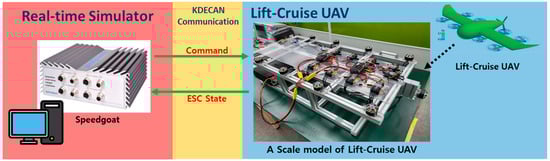
Figure 1.
Conceptual diagram of building of real-time simulation environment using real-time simulator and KDECAN communication.
2.1. Real-Time Simulation Modeling Configuration
A real-time simulator is used to imitate control communication commands through MATLAB Simulink modeling. Figure 2 depicts the entire simulation modeling block for constructing the real-time simulation environment. In the MATLAB Simulink modeling, control communication commands are transmitted through the frame ID corresponding to each ESC ID to drive each motor and configure the ESC status feedback. The left side of the configuration diagram contains the TX section, which is for sending commands; the right side contains the RX section, which is for receiving the ESC status; the IO614 module section, which is at the top, verifies the communication status and configures the communication attributes. The commander block, which is at the bottom, is used in conjunction with the TX section to enable the operator to adjust the speed commands easily using each throttle adjustment slider block, and a separate monitoring section is modeled to monitor the ESC status received by the RX section. In addition, the data inspector function is used to confirm the power consumption of each ESC and the overall power consumption of all installed ESCs.
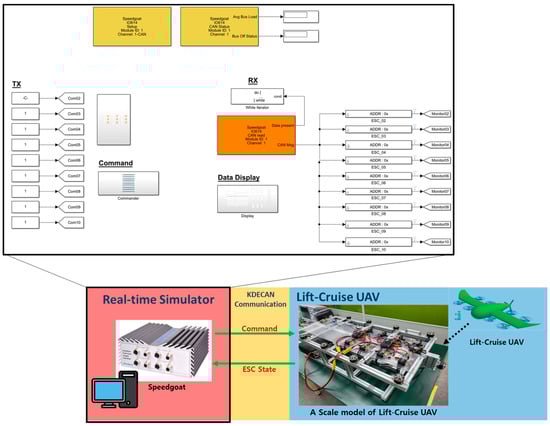
Figure 2.
Configuration of real-time simulation modeling block.
The target hardware for real-time simulation is a reduced-size lift–cruise UAV with an electric propulsion system. The two power distribution units (PDU) that distribute power to the nine ESCs and the CAN bus line from the controller are wired, as shown in Figure 3. In an actual electric propulsion system, a middle terminal, such as a thrust PDU, is required because of the long distance between each ESC and the controller. However, this terminal is excluded from this experiment because the connection target is a reduced-size model. In addition, as seen in Figure 3, the modeling configuration is designed to be circular for communication redundancy, but the CAN bus line is arranged in a daisy chain through each ESC, and termination resistors are installed. Each ESC ID ranges from 2 to 10 (according to the KDECAN protocol, the starting number is 2). Simulink model that generates the control communication commands (Figure 3) takes over the role of the Fligt Controller during real-time simulation.
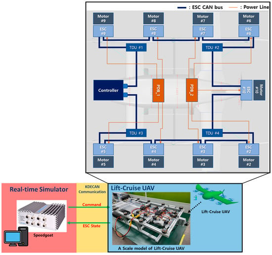
Figure 3.
Configuration of real-time simulation modeling.
2.2. Detailed Modeling of TX and RX Parts
The modeling of the TX part is detailed in Figure 4. It consists of nine TX command generation models, which send commands to the nine ESC IDs. Each of the nine blocks further divides the commands into two frame IDs: one for sending throttle commands for motor control and one for sending signal commands to receive the ESC status data. For example, the frame ID for sending throttle commands to ESC number 2 is ID02_Com, and the signal command for requesting data is designated as ID02_Get_Data. This is designed in the MATLAB ST code script for easy modification and addition of commands for other IDs in the future. Additionally, the KDECAN protocol follows the big-endian format, where the most significant bit is stored at the lowest memory address. Therefore, in the Simulink model, which has little endian as the default format, the byte reversal function block is used to change the endianness.
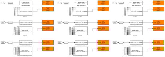
Figure 4.
Modeling of TX part.
The detailed modeling configuration of the RX part is shown in Figure 5. A total of nine blocks are modeled for the number of ESCs connected to this model. Like the TX part, the RX part requests data through the frame ID assigned to each ESC via the address (ADDR) variable, and a block is modeled to match the big-endian format. Five types of data are received from the ESC: voltage, current, RPM, temperature, and flag (error signal). Since each of these data is received in hex format, the modeling is configured by adjusting the scale of each data value for easier monitoring. The voltage, current, and temperature data are converted using Equations (1)–(3), respectively, to use them for data monitoring. The following equations show an example of data conversion using arbitrary values:
Example
Voltage Data = Received Data/Scale Factor
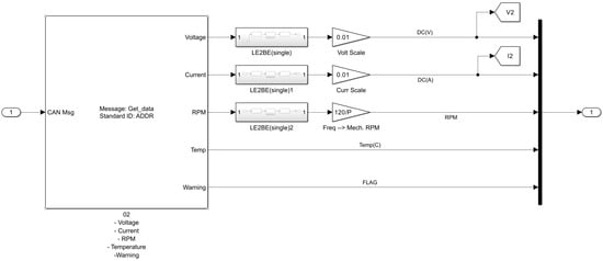
Figure 5.
Modeling of RX part.
- -
- Received Data = Hex: 06 2D 00 00 00 00 00 00 = Dec: 1581
- -
- Scale Factor = 100
- -
- Voltage Data = 1581/100 = 15.81 V
Current Data = Received Data/Scale Factor
- -
- Received Data = Hex: 06 2D 00 00 00 00 00 00 = Dec: 1581
- -
- Scale Factor = 100
- -
- Voltage Data = 1581/100 = 15.81 A
Temperature Data = Received Data
- -
- Received Data = Hex: 1E 00 00 00 00 00 00 00 = Dec: 30
- -
- Temperature Data = 30 °C
The RPM data are obtained by analyzing the signal supplied to one of the three phases of the motor from the ESC. This signal is a sine wave that corresponds to each cycle crossing a motor pole. Dividing the frequency of this sine wave by the number of motor poles yields the rotational frequency (in hertz), which is then multiplied by 60 to convert it to RPM. Equation (4) provides an example of RPM data conversion using an arbitrary value (22 motor poles), and Equation (5) explains the RPM data scale.
Example
RPM Data = Received Data × Scale Factor
- -
- Received Data = Hex: 01 DD 00 00 00 00 00 00 = Dec: 477
- -
- Scale Factor = 60 × (2/22)
- -
- RPM Data = 2061 RPM
Mechanical RPM = Electrical RPM (frequency) × 60 × (2/motor poles)
The signal indicating the error type is obtained from the flag data and distinguished by assigning stall protection (1), over temperature (2), overload protection (3), over voltage (4), low voltage (5), and voltage cutoff (6) to bits 0 to 5.
2.3. KDECAN Communication Packet Analysis and ID and Object Composition
The frame ID, object address, and data can be analyzed by referring to the documentation provided by KDE Direct regarding the KDECAN protocol. The basic structure of the KDECAN protocol consists of a standard frame ID, which is composed of a 1-bit source, 5-bit ESC ID, and 5-bit object, as shown in Figure 6.
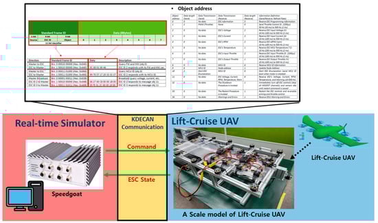
Figure 6.
KDECAN protocol document.
The source bit denotes commands sent from the master to the ESC as 0 and data sent from the ESC to the master as 1, as shown in Equations (6) and (7), respectively.
Master to ESC = bin: 0 (1-bit source)
ESC to Master = bin: 1 (1-bit source)
The ESC ID bit is determined by the assigned ESC ID, as shown in Equations (8)–(10).
ESC ID 01 = bin: 0 0 0 0 1 (5-bit ESC ID)
ESC ID 02 = bin: 0 0 0 1 0 (5-bit ESC ID)
ESC ID 03 = bin: 0 0 0 1 1 (5-bit ESC ID)
The object bit defines various pieces of information associated with each assigned address, allowing users to select and use the desired information. In this study, 11 is set as the object address for requesting and receiving the five ESC status parameters (voltage, current, RPM, temperature, and flag) in an 8-byte data format simultaneously. This is expressed as Equation (11).
Object 11 = bin: 0 1 0 1 1 (5-bit object)
For example, if the master requests data for object 11 from ESC ID 02, the frame ID will be assigned to each bit as follows: master to ESC = bin: 0 (1-bit source), ESC ID 02 = bin: 0 0 0 1 0 (5-bit ESC ID), object 11 = bin: 0 1 0 1 1 (5-bit object). Therefore, the frame ID is expressed as Equation (12).
Frame ID = bin: 0 00010 01011 (11-bit frame ID, hex: 0 × 4B)
In this paper, although a total of nine ESC IDs are used, the actual frame IDs assigned for communication depend on various factors, such as the object used to send data and whether the data are sent from the master to the ESC or from the ESC to the master. Therefore, as shown in Table 1, the configuration of frame IDs for communication with the nine ESCs consists of nine throttle command frame IDs, nine data request command frame IDs, and nine data receive frame IDs, resulting in a total of 27 frame IDs written in MATLAB ST code.

Table 1.
Parameter setup for Frame IDs.
3. Construction of Real-Time Simulation Test Environment Experiment
The reduced-size UAV model was developed for the real-time simulation testing of a lift–cruise UAV. The model had an aluminum profile and was equipped with an electric propulsion system. It consisted of eight lift motors and one cruise motor, all powered by T-Motor’s MN4014 KV400. The ESCs were KDE’s UAS40UVC, and two Mauch power distribution boards (PDBs) were installed in the center for power distribution. The model was driven by control communication commands using a Speedgoat Baseline S real-time target machine; these commands were implemented using MATLAB Simulink modeling and real-time simulation. Therefore, the control communication commands were simulated in real time, and the monitoring values reflected the real-time status of the hardware.
The establishment of the real-time simulation environment was verified through the following process. First, the communication packets during the exchange of control communication commands between one master and one ESC were analyzed and confirmed. Then, the independent control of each motor with the nine ESCs was verified using the control communication commands. Finally, the monitoring quality of the desired information during the operation of the nine motors through the ESCs was checked.
3.1. Setup of Real-Time Simulation Environment
The real-time simulator equipment and PC were set up in an experimental environment, as shown in Figure 7, which includes the specific communication packet being checked using one ESC and one motor. The packet analysis of the control communication commands was performed using an oscilloscope with a CAN analyzer and a high-bandwidth probe. The transmission time of a single communication packet was checked, and the required communication speed was calculated. This was done to determine the modeling sampling time for the real-time simulation. The MATLAB version was 2021b, and the specifications of the real-time simulator are shown in Table 2.
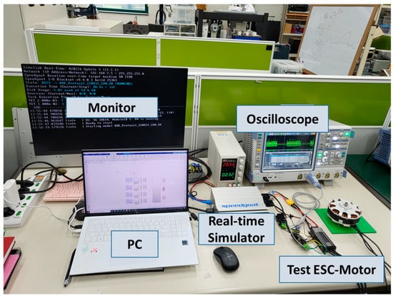
Figure 7.
Real-time simulation environment setup for test communication.
Table 2.
Specifications of real-time simulator.
Figure 8 shows the target hardware driven by control communication commands during the real-time simulation. It is a reduced-size version of a lift–cruise UAV and configured with nine ESCs, nine motors, and two PDBs as an electric propulsion system with only motors attached (without propeller load). The numbers in Figure 8 are the ESC and motor IDs; the starting number in the KDECAN protocol is 2, so the IDs were specified accordingly. The motors with IDs 2 to 9 are the lift motors, which operate during takeoff, and motor ID 10 is the cruise motor, which operates during cruising. Each of the nine ESCs receives and transmits control communication commands through the CAN bus line daisy chain. The specifications of the ESCs, motors, and PDBs are shown in Table 3, Table 4 and Table 5, respectively.
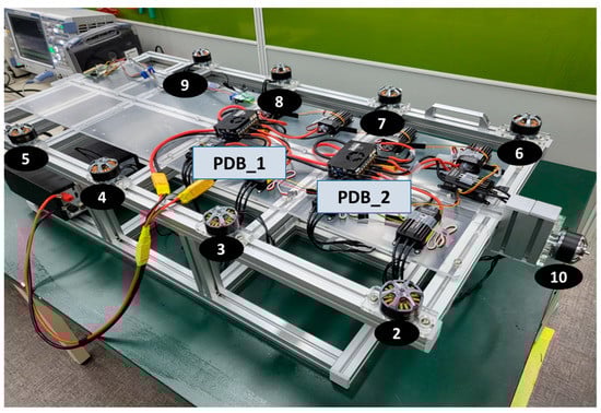
Figure 8.
Scale model of lift–cruise UAV.
Table 3.
Specifications of ESC.
Table 4.
Specifications of motor.
Table 5.
Specifications of PDB.
3.2. Measurement and Analysis of KDECAN Signals
First, we examined a communication packet between an ESC and a motor. Using measurement equipment, we confirmed that the contents of the packet were structured as shown in Figure 9 and then compared it with the KDECAN protocol document.
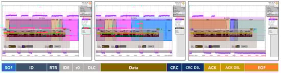
Figure 9.
KDECAN communication packet measurement screen.
KDECAN communication packets are generally transmitted via CAN buses. Each packet typically consists of a start bit, a destination ID, a transmitter ID, the data, cyclic redundancy check (CRC), and an end bit. The start bit indicates that communication has begun; the destination ID is used to identify the data, including the information exchanged between the controller and the target device (ESC); the CRC is used to protect the integrity of the packet. The KDECAN protocol consists of commands and responses. The controller sends commands, and the target device (ESC) receives them and sends a corresponding response. These commands and responses are transmitted as data within KDECAN communication packets, and analyzing these packets enables effective communication between the controller and the target device (ESC). This allows the controller to monitor and control the state of the target device (ESC), and the target device (ESC) can provide necessary information to the controller. Data types and CRC algorithms can be verified by referring to STM32 AN4187, as it was used the internal CRC peripheral of the STM32 product family.
After the packet configuration was verified, the frame ID and data exchanged between the master and each ESC during communication were confirmed using the measured raw data from the measurement equipment. The operation between the master and ESC ID 2 was confirmed. The frame ID value was defined as follows using Equation (12):
- Frame ID @master → ESC ID 02
- -
- Throttle command = hex: 41
- -
- Request ESC voltage = hex: 42
- -
- Request ESC current = hex: 43
- -
- Request motor RPM = hex: 44
- Frame ID @ESC ID → master
- -
- ESC voltage = hex: 442
- -
- ESC current = hex: 443
- -
- Motor RPM = hex: 444
Initially, communication was performed by assigning separate frame IDs to each requested information to obtain the desired data for communication verification. However, ultimately, the frame ID was modified to use object 11 to receive all necessary data (voltage, current, RPM, temperature, and flag signal) in one packet’s internal data simultaneously.
The speed command of each motor was transmitted in the form of a remote-control pulse-width modulation (RC-PWM) signal, where the pulse-width represents the ratio of the speed throttle. Typically, an RC-PWM signal has a pulse-width of 1000–2000 μs. Therefore, at the minimum speed throttle, a pulse-width of 1000 μs was generated for controlling the motor speed. The ESC used in the experiment was calibrated so that the idle state of the motor (0% throttle) was achieved with a 1100 μs pulse-width signal; that is, the motor started running at greater pulse widths. Figure 10, Figure 11 and Figure 12 show the raw data obtained by observing the communication data using the oscilloscope at RC-PWM signal pulse widths of 1100, 1175, and 1200 μs, respectively. The current and rpm information corresponding to each pulse-width could be confirmed as data values in the response signal, with a DC input voltage of 24 V.
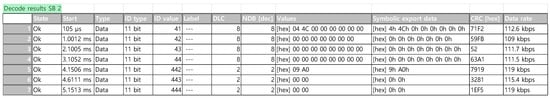
Figure 10.
Data value of KDECAN communication packets (RC-PWM 1100 μs).
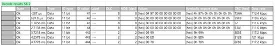
Figure 11.
Data value of KDECAN communication packets (RC-PWM 1175 μs).
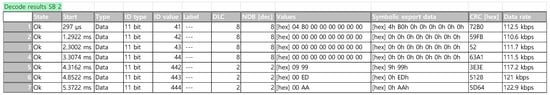
Figure 12.
Data value of KDECAN communication packets (RC-PWM 1200 μs).
Because multiple ESCs needed to be operated, the communication speed was appropriately adjusted to optimize the real-time simulation environment considering the amount of communication required for smooth control and monitoring. Figure 10, Figure 11 and Figure 12 show the data packet information for simple communication testing at 125 Kbps. The maximum baud rate that could be used was 1 Mbps. When the communication packets were measured at the maximum baud rate (1 Mbps), 350 μs was required to send and receive one ESC ID and control communication command, as shown in Figure 13. Therefore, the total time required for the communication control of all nine motors and ESCs was at least 9 × 350 μs = 3.15 ms. The sampling time for the entire real-time simulation should be at least 3.3 ms to ensure suitable communication modeling with some margin. The overall communication load ratio was also monitored in real time during the simulation test to ensure communication stability.
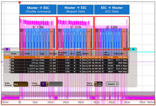
Figure 13.
Communication packet measurement screen (@1 Mbps).
Through these experiments and waveform measurements, the control communication commands driving the ESCs were verified, and real-time data from each of the nine motors in the lift–cruise UAV electric propulsion system were monitored while they were being driven, as shown in Figure 14. The bottom graphs in Figure 14 show the real-time power consumption being shown by the monitoring system using the data inspector feature while the electric propulsion system was operating. In the monitoring system model, the state of each ESC (voltage, current, RPM, temperature, and flag signal) and power consumption were designed to be seen easily. The nine display blocks on the right display the data values of the status of each ESC. The nine display blocks on the left allow the user to check the power consumption over time.
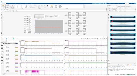
Figure 14.
Monitoring system blocks for real-time simulation.
4. Conclusions
Due to population growth and the overcrowding of ground transportation systems around the world, aerial mobility has emerged as a new alternative to address transportation and environmental issues. In light of this, electric propulsion systems are being actively studied. Various testing environments are needed to verify the stability of such systems. Therefore, this study proposes the establishment of a real-time simulation test environment for the electric propulsion systems of UAVs with a lift–cruise configuration. The real-time simulation environment was designed to operate a UAV’s electric propulsion system based on the KDECAN communication protocol, which is one of the communication protocols used within these aircraft, and to enable state monitoring. Control and communication commands were created through modeling in MATLAB Simulink, and the status of each ESC, which drove the motors, was monitored in real time. Thus, a real-time simulation environment that integrates hardware and simulation, rather than a simple digital simulation, was constructed. A reduced-size lift–cruise UAV electric propulsion system was created. Its communication wiring and power distribution were similar to those of an actual system, enabling experiments to be conducted in an environment similar to that of an actual electric propulsion system. This can serve as a foundation for the implementation of distributed electric propulsion technology, which has recently gained attention in the aviation field as a next-generation aircraft. Distributed electric propulsion systems divide a small number of large propulsion units into multiple small propulsion units distributed throughout the aircraft. Such systems reduce the risk of catastrophic failures and offer advantages in terms of noise reduction and efficiency. Additionally, integrating the propulsion units with the aircraft’s shape allows the aircraft to achieve its maximum performance. Due to the placement of multiple motors in distributed electric propulsion systems, the importance of control and communication commands is elevated. Therefore, the establishment of a real-time simulation environment for control and communication commands, as studied in this paper, can serve as a crucial testing environment for distributed electric propulsion systems.
In the real-time simulation test environment, the reliability of the electric propulsion system was confirmed by comparing the data measured by the monitoring system with the actual data. In addition, the control communication commands for operating the electric propulsion system were implemented through analysis and measurement of the communication packets.
We constructed a real-time simulation environment for the electric propulsion systems of UAVs and derived related research and development results. Using this simulation environment, we analyzed the construction of a simulation environment where various situations that may occur during UAV flight can be simulated. We measured changes in signal data, such as voltage, current, RPM, and temperature, in real time according to changes in the operating conditions of the electric propulsion system. We also established a foundation for deriving various measures to improve system stability and performance. Ultimately, we presented a technological basis for identifying and addressing various potential problems in real-world environments. Such technological advances can provide alternative solutions in the field of air mobility. Specifically, the results of this study will help enhance UAV safety and reliability and play a significant role in addressing transportation and environmental sustainability.
Author Contributions
Conceptualization, K.L. and M.G.; methodology, K.L; software, M.G. and J.P.; validation, M.G., J.P. and K.L.; investigation, K.L. and M.G.; writing-original draft preparation, M.G.; writing-review and editing, K.L.; supervision, J.K.; project administration, K.L.; funding acquisition, K.L. All authors have read and agreed to the published version of the manuscript.
Funding
This research was supported by Unmanned Vehicles Core Technology Research and Development Program through the National Research Foundation of Korea (NRF) and Unmanned Vehicle Advanced Research Center (UVARC) funded by the Ministry of Science and ICT, the Republic of Korea (NRF-2020M3C1C1A01086539).
Data Availability Statement
No new data were created or analyzed in this study. Data sharing is not applicable to this article.
Conflicts of Interest
The authors declare no conflict of interest.
References
- Joshi, D.; Deb, D.; Muyeen, S.M. Comprehensive review on electric propulsion system of unmanned aerial vehicles. Front. Energy Res. 2022, 10, 752012. [Google Scholar] [CrossRef]
- Araújo, J.F.B.; Pedrosa, H.M.; Rodrigues, M.C.B.P.; Barbosa, P.G. Real-time hardware-in-the-loop simulation of components of an electric vehicle powertrain: Modeling and implementation. In Proceedings of the 2016 12th IEEE International Conference on Industry Applications (INDUSCON), Curitiba, PR, Brazil, 20–23 November 2016; pp. 1–7. [Google Scholar]
- Zhang, B.; Song, Z.; Zhao, F.; Liu, C. Overview of propulsion systems for unmanned aerial vehicles. Energies 2022, 15, 455. [Google Scholar] [CrossRef]
- Wen, J.; Ji, H.; Wang, H.; Zhang, M.; Li, D.; Wu, J. Design of a real-time UAV fault injection simulation system. In Proceedings of the 2019 IEEE International Conference on Unmanned Systems (ICUS), Beijing, China, 17–19 October 2019; pp. 767–772. [Google Scholar] [CrossRef]
- Gorospe, G.E.; Kulkarni, C.S. A novel UAV electric propulsion testbed for diagnostics and prognostics. In Proceedings of the 2017th IEEE AUTOTESTCON, Schaumburg, IL, USA, 9–15 September 2017; pp. 1–6. [Google Scholar] [CrossRef]
- Wandarosanza, R.; Trilaksono, B.R.; Hidayat, E. Hardware-in-the-loop simulation of UAV hexacopter for chemical hazard monitoring mission. In Proceedings of the 2016 6th International Conference on System Engineering and Technology (ICSET), Bandung, Indonesia, 3–4 October 2016; pp. 189–193. [Google Scholar] [CrossRef]
- KDECAN. Available online: https://forum.opencyphal.org/uploads/default/original/1X/9e80b97324ad566a741dbc150359caf7ff35dc32.pdf (accessed on 15 April 2023).
- Vahana. Available online: https://acubed.airbus.com/projects/vahana/ (accessed on 15 April 2023).
- Lobo, L.M.; Dufour, C.; Mahseredjian, J. Real-time simulation of more-electric aircraft power systems. In Proceedings of the 2013 15th European Conference on Power Electronics and Applications (EPE), Lille, France, 2–6 September 2013; pp. 1–10. [Google Scholar] [CrossRef]
- Wang, D.; Yang, S.; Wang, L.; Liu, W. Hardware-in-the-loop simulation for aircraft electric power system. In Proceedings of the 2016 International Conference on Electrical Systems for Aircraft, Railway, Ship Propulsion and Road Vehicles & International Transportation Electrification Conference (ESARS-ITEC), Toulouse, France, 5–8 December 2016; pp. 1–5. [Google Scholar] [CrossRef]
- Osman, A.; Alijani, M. Energy-efficient techniques for UAVs in communication-based applications. In Proceedings of the 2021 25th International Conference on Automation and Computing (ICAC), Portsmouth, UK, 2–4 September 2021; pp. 1–6. [Google Scholar] [CrossRef]
- Lu, P.; Geng, Q. Real-time simulation system for UAV based on MATLAB/Simulink. In Proceedings of the 2011 IEEE 2nd International Conference on Computing, Control and Industrial Engineering, Wuhan, China, 20–21 August 2011; pp. 399–404. [Google Scholar] [CrossRef]
- UAVCAN. Available online: https://legacy.uavcan.org/Specification/2._Basic_concepts/ (accessed on 15 April 2023).
- Shixianjun; Jiakun, S.; Hongxing, L. Hardware-in-the-loop simulation framework design for a UAV embedded control system. In Proceedings of the 2006 Chinese Control Conference, Harbin, China, 7–11 August 2006; pp. 1890–1894. [Google Scholar]
- Yoo, C.; Kang, Y.; Park, B. Hardware-in-the-loop test for fault diagnosis system of tilt rotor UAV. In Proceedings of the 2008 International Conference on Control, Automation and Systems, Seoul, Republic of Korea, 14–17 October 2008; pp. 320–323. [Google Scholar] [CrossRef]
- Yoo, C.; Kang, Y.; Park, B. Hardware-In-the-Loop simulation test for actuator control system of Smart UAV. In Proceedings of the ICCAS 2010, Gyeonggi-do, Republic of Korea, 27–30 October 2010; pp. 1729–1732. [Google Scholar] [CrossRef]
- Pizetta, I.H.B.; Brandão, A.S.; Sarcinelli-Filho, M. A Hardware-in-the-loop platform for rotary-wing unmanned aerial vehicles. In Proceedings of the 2014 International Conference on Unmanned Aircraft Systems (ICUAS), Orlando, FL, USA, 27–30 May 2014; pp. 1146–1157. [Google Scholar] [CrossRef]
- Baseline real-Time Target Machine—S. Available online: https://www.speedgoat.com/products-services/real-time-target-machines/baseline-real-time-target-machine (accessed on 23 April 2023).
- KDE-UAS40UVC. Available online: https://www.kdedirect.com/collections/uas-multi-rotor-electronics/products/kde-uas40uvc-40a-uhv-electronic-speed-controller-esc-for-multi-rotor-uas-series (accessed on 23 April 2023).
- MN4014 KV 400. Available online: https://store.tmotor.com/goods-348-MN4014+KV400.html (accessed on 23 April 2023).
- MAUCH PL 2 × 200 A PDB. Available online: https://www.mauch-electronic.com/pl-2x-200a-pdb (accessed on 23 April 2023).
Disclaimer/Publisher’s Note: The statements, opinions and data contained in all publications are solely those of the individual author(s) and contributor(s) and not of MDPI and/or the editor(s). MDPI and/or the editor(s) disclaim responsibility for any injury to people or property resulting from any ideas, methods, instructions or products referred to in the content. |
© 2023 by the authors. Licensee MDPI, Basel, Switzerland. This article is an open access article distributed under the terms and conditions of the Creative Commons Attribution (CC BY) license (https://creativecommons.org/licenses/by/4.0/).