Article

A Novel High-Power Rotary Waveguide Phase Shifter Based on Circular Polarizers

1
Northwest Institute of Nuclear Technology, Xi’an 710024, China
2
College of Advanced Interdisciplinary Studies, National University of Defense Technology, Changsha 410073, China
*
Author to whom correspondence should be addressed.
Electronics 2023, 12(13), 2963; https://doi.org/10.3390/electronics12132963
Submission received: 15 May 2023 / Revised: 28 June 2023 / Accepted: 1 July 2023 / Published: 5 July 2023
(This article belongs to the Special Issue Advanced RF, Microwave Engineering, and High-Power Microwave Sources)

Abstract

:
This paper presents a novel high-power rotary waveguide phase shifter based on circular polarizers specifically engineered for high-power microwave (HPM) applications. The phase shifter is capable of performing a precise 360° linear phase shift through rotation and consists of three parts: a linearly polarized to left-handed circularly polarized (LP-LHCP) mode converter, a left-handed to right-handed circularly polarized (LH-RHCP) mode converter, and a linearly polarized to right-handed circularly polarized (LP-RHCP) mode converter. This paper analyzes the phase-shifting principle, optimizes the three parts of the X-band rotary waveguide phase shifter, and conducts simulation studies on the entire phase shifter, which is made of aluminum. The results show that the reflection is less than −20 dB and the insertion loss is below 0.3 dB within 9.5 GHz to 10.2 GHz. The phase shift is equal to twice the rotation angle within this frequency range. Specifically, the phase shifter can achieve a linear phase shift of 360° when rotated from 0° to 180°, with a maximum deviation of less than 1.2°. Moreover, the power-handling capacity of the phase shifter in vacuum exceeds 242 MW. In the meantime, a prototype of a phase shifter was manufactured, and the experimental results are in good agreement with the simulation results.

1. Introduction

A high-power microwave (HPM) phase shifter is a crucial component in HPM coherent synthesis systems and HPM array antennas [1,2,3]. Its performance directly impacts the technical indicators of the system. Therefore, it is significant to research phase shifters with a low insertion loss, high phase-shifting accuracy, wide operating bandwidth, and high-power capacity.
According to the implementation method, microwave phase shifters can be divided into non-mechanical and mechanical types. The most representative non-mechanical phase shifters include ferrite [4,5,6], PIN diodes [7,8], and dielectric-loaded phase shifters [9,10]. Due to limitations in the working mechanism and the breakdown threshold of dielectric materials, the power-handling capacity of non-mechanical phase shifters is generally lower than megawatt levels, making them unsuitable for HPM applications. Mechanical phase shifters can be divided into push–pull and rotary waveguide types according to the adjustment method. Currently, push–pull waveguide phase shifters, such as the waveguide broad-wall adjustable phase shifter [11], the T-shaped rectangular waveguide phase shifter [12], and the phase shifter based on a dual circular polarizer [13], are commonly used in HPM areas to achieve microwave phase adjustment. The waveguide broad-wall adjustable phase shifter is designed to modify the width dimension of the waveguide, thereby altering the propagation constant and achieving a phase shift. However, the non-linear relationship between the phase and the displacement distance poses a challenge for achieving high-precision phase adjustment. Both the T-shaped rectangular waveguide phase shifter and the phase shifter based on a dual circular polarizer are capable of achieving linear phase adjustment. The T-shaped rectangular waveguide phase shifter utilizes waveguide folding technology to directly alter the length of the microwave transmission path, thereby achieving the desired phase. On the other hand, the phase shifter based on a dual circular polarizer achieves a phase adjustment by sliding the short-circuit metal plug and modifying the transmission path of the circularly polarized (CP) wave. These two phase shifters have made significant advancements in solving high-precision phase adjustments. However, it is worth noting that the push–pull structure employed in these phase shifters generally exhibits two drawbacks: first, they require space for the short circuit slider to move in the waveguide, which makes the HPM system difficult to maintain a high vacuum level and increases the complexity of the HPM vacuum system; second, the sliding of the short circuit slider along the inner wall of the waveguide can cause wear and reduce the service life of the phase shifter.
Considering the limitations of push–pull phase shifters discussed above, researchers in the HPM field are increasingly turning to rotary phase shifters due to their more compact structure and longer lifespan. The waveguide rotating contact surface of a rotary waveguide phase shifter is less prone to wear, making it more durable. There are mainly three types of rotary waveguide phase shifters in the literature: the pressure elliptical waveguide phase shifter [14], the waveguide gap bridge rotary adjustable phase shifter [15], and the TEM-mode phase shifter [16]. The pressure elliptical waveguide phase shifter has a wide working frequency band, but its phase shift has a nonlinear relationship with the rotation angle, resulting in lower phase-shifting accuracy. The waveguide gap bridge rotary adjustable phase shifter consists of a waveguide gap bridge, two circular polarizers, and two inverters, making its structure more complex. To achieve linear phase adjustment, this phase shifter requires the simultaneous rotation of two inverters at the same angle, making its adjustment process more complicated. The L-band TEM-mode rotary waveguide phase shifter comprised two identical TEM-mode to coaxial CP TE11 mode converters. Each converter consists of two coaxial circular waveguides, two metal cones, and four 90°–90° bent rectangular waveguides. To achieve the conversion of the coaxial CP TE11 mode, the lengths of the four rectangular waveguides must be carefully designed so that the lengths of the adjacent waveguides differ by one-fourth of the operating wavelength. As a result, this phase shifter has a relatively narrow operating bandwidth. Furthermore, due to its complex structure and high machining precision requirements, it is challenging to apply this phase shifter in high-frequency ranges.
A high-power rotary waveguide phase shifter based on circular polarizers is presented. As illustrated in Figure 1, the structure of the phase shifter comprises a linearly polarized to left-handed circularly polarized (LP-LHCP) mode converter, a left-handed to right-handed circularly polarized (LH-RHCP) mode converter, and a linearly polarized to right-handed circularly polarized (LP-RHCP) mode converter. The entire phase shifter exhibits mirror symmetry. By rotating the LH-RHCP mode converter, a 360° linear phase shift can be achieved, with the phase shift being twice the rotation angle. Through the simulation analysis and experimental testing of the X-band rotary waveguide phase shifter, it has been demonstrated that the proposed phase shifter possesses advantages such as a high phase-shifting accuracy, low insertion loss, and wide operating bandwidth.
This paper is organized as follows. Section 2 elaborates on the phase-shifting principle of the proposed phase shifter in detail. Section 3 presents the optimization results for the three parts of the X-band rotary waveguide phase shifter. Section 4 conducts a simulation analysis of the entire phase shifter. Section 5 presents the developed prototype of the phase shifter and its experimental results. Moreover, the proposed phase shifter is compared with previous related studies, and the future improvements are discussed in Section 6. Finally, a conclusion is made in Section 7.

2. Phase-Shifting Principle

The LH-RHCP mode converter serves as a crucial component for phase adjustment in the presented high-power rotary waveguide phase shifter. It comprised two mirror-symmetric circular polarizers, which can convert the input LHCP TE11 mode to LP TE11 mode and then to RHCP TE
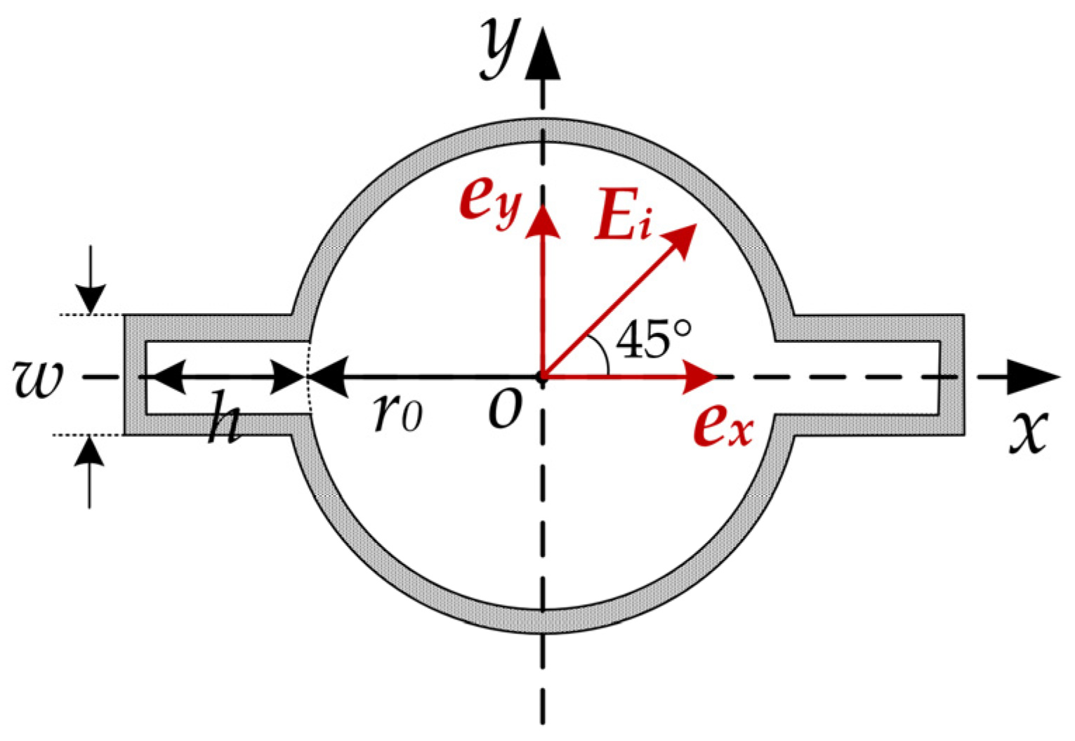
11 mode. The circular polarizer is composed of a circular waveguide and a pair of rectangular grooves protruding from both sides of the waveguide, as shown in Figure 1. To elucidate the principle underlying the conversion between LP and CP TE11 mode by the circular polarizer, two orthogonal coordinate systems, x-y and ex-ey, are established as depicted in Figure 2. In this context, ex is parallel to the direction of the rectangular grooves of the circular polarizer, while ey is perpendicular to that direction.
In order to satisfy the requirement of the CP electric fields having equal amplitudes and a phase difference of 90°, the direction of the input electric field Ei must be oriented at an angle of 45° (resulting in an LHCP wave) or −45° (resulting in an RHCP wave) with the rectangular grooves. When the input electric field Ei is oriented at 45° with the rectangular grooves, it can be decomposed into two orthogonal electric field components along the ex and ey directions, respectively, as shown in Equation (1). Due to the different cavity structures in the ex and ey directions, their electric field propagation constants (βx and βy) and transmission efficiencies (τx and τy) are also distinct. For the TE11 mode in the ey direction, the electric field is primarily concentrated in the middle of the circular waveguide, with a relatively low field strength at the rectangular grooves on both sides. Consequently, the discontinuity caused by the rectangular grooves has minimal impact on the transmission efficiency of electromagnetic waves in that direction, i.e., τy ≈ 1. The transmission efficiency τx of electromagnetic waves in the ex direction is mainly related to the thickness w and height h of the rectangular cavity. Therefore, by selecting the appropriate parameters, a high transmission efficiency can be achieved, i.e., τx ≈ 1. Since the electric field propagation constant βy perpendicular to the direction of the rectangular grooves is greater than the electric field propagation constant βx along the direction of the rectangular grooves, adjusting the length d of the rectangular grooves accordingly can result in a 90° phase difference between the electric fields in both directions, thereby forming an LHCP wave, as shown in Equation (2).
E i = 2 2 E 0 ( e x + e y ) e i δ e i ω t ,
E 0 = 2 2 E 0 ( τ x e i β x d e x + τ y e i β y d e y ) e i δ e i ω t 2 2 E 0 ( e x + e i ( β y β x ) d e y ) e i ( β x d δ ) e i ω t ,
where δ is the initial phase, and ω is the angular frequency.
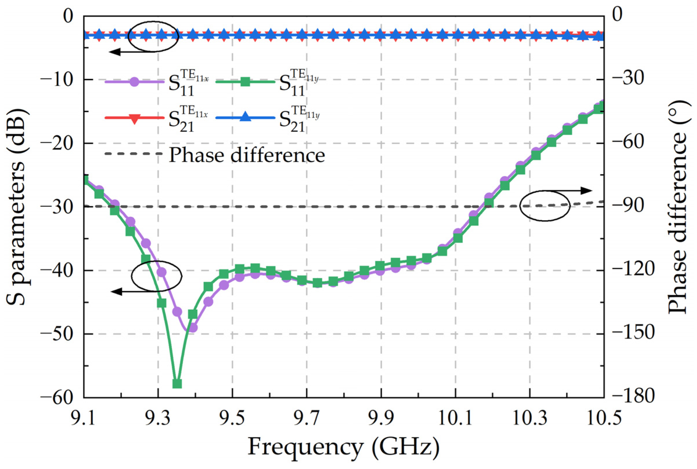
The circular polarizer can also be regarded as a four-port waveguide device, where ports 1 and 2 correspond to the degenerate TE11x mode (TE11 mode polarized along the x-axis) and TE11y mode (TE11 mode polarized along the y-axis) of the input port, respectively, while ports 3 and 4 correspond to the degenerate TE11x mode and TE11y mode of the output port, respectively. The generalized scattering matrix of the circular polarizer can be expressed as
S = 1 2 [ 0 0 1 + i 1 i 0 0 1 i 1 + i 1 + i 1 i 0 0 1 i 1 + i 0 0 ] ,
To illustrate the characteristics of the circular polarizer, for the TE11x mode and TE11y mode wave incident, respectively, at the input port with a normalized amplitude and an equal phase of 0°, corresponding to input vectors a1 = [1,0,0,0]T and a2 = [0,1,0,0]T, the output vectors are b1 = S′·a1 = 2 / 2 0 , 0 , 45 ° , 45 ° T and b2=S′·a2 = 2 / 2 0 , 0 , 45 ° , 45 ° T , respectively. Namely, when the input port electric field is the TE11x mode, the circular polarizer can output an LHCP wave. Conversely, when the input port electric field is the TE11y mode, the circular polarizer can output an RHCP wave.
S = [ 0 0 0 1 0 0 1 0 0 1 0 0 1 0 0 0 ] ,
When an LHCP wave with a normalized amplitude and an initial phase of 0° is injected into the LH-RHCP mode converter, corresponding to the input vector a = 2 / 2 1 , i , 0 , 0 T , the output vector is b = S·a = 2 / 2 0 , 0 , i , 1 T , the conversion from LHCP to RHCP TE11 mode is achieved. Similarly, when an RHCP wave is input, the LHCP wave can be output.
The LH-RHCP mode converter rotates by an angle θ, and the ex-ey coordinate system also rotates accordingly. The rotated coordinate system is defined as e1-e2, as illustrated in Figure 3.
The relationship between the ex-ey coordinate system and the e1-e2 coordinate system is given by
{ e x = cos θ e 1 + sin θ e 2 e y = sin θ e 1 + cos θ e 2 [ e x e y ] = [ cos θ sin θ sin θ cos θ ] [ e 1 e 2 ] = T 12 [ e 1 e 2 ] ,
{ e 1 = cos θ e x sin θ e y e 2 = sin θ e x + cos θ e y [ e 1 e 2 ] = [ cos θ sin θ sin θ cos θ ] [ e x e y ] = T x y [ e x e y ] ,
where T12 and Txy are the coordinate transformation matrices.
For the LH-RHCP mode converter input, an LHCP wave with a normalized amplitude and an initial phase of 0°, the input port electric field can be expressed as
E i = 2 2 ( e x + i e y ) = 2 2 [ 1 i ] [ e x e y ] ,
Substituting Equation (5) into (7), which can be deduced as
E i = 2 2 [ 1 i ] T 12 [ e 1 e 2 ] = 2 2 [ e i θ i e i θ ] [ e 1 e 2 ] ,
In the e1-e2 coordinate system, the total input electric field vector is further written as
E i = 2 / 2 [ e i θ , i e i θ , 0 , 0 ] T ,
By combining Equations (4) and (9), the total output electric field vector of the e1-e2 coordinate system can be obtained.
E 0 = E i S = 2 / 2 [ 0 , 0 , i e i θ , e i θ ] T ,
The expression for the output port electric field can be described as
E 0 = 2 2 [ i e i θ e i θ ] [ e 1 e 2 ] ,
Moreover, the output port electric field of the ex-ey coordinate system can be rewritten as follows by substituting Equation (6) into (11).
E 0 = 2 2 [ i e i θ e i θ ] T x y [ e x e y ] = 2 2 [ i e i 2 θ e i 2 θ ] [ e x e y ] = 2 2 e i 2 θ ( i e x + e y ) ,
By comparing Equations (7) and (10), it can be observed that when the LH-RHCP mode converter rotates by an angle of θ, the input LHCP wave can be converted to the RHCP wave output, and the microwave phase undergoes a change of 2θ. Therefore, the phase shift Δφ and the angle of rotation Δθ satisfy the following formula.
Δ φ = 2 Δ θ ,

3. Structure and Design

Figure 1 illustrates the structure of the high-power rotating waveguide phase shifter. It consists of three parts: an LP-LHCP mode converter, an LH-RHCP mode converter, and an LP-RHCP mode converter. These three parts are coaxially distributed along the center axis of the phase shifter. The LP-LHCP mode converter and the LP-RHCP mode converter are fixed, while the LH-RHCP mode converter can rotate around the central axis. The whole phase shifter has mirror symmetry along the center plane of the phase shifter. To ensure high transmission efficiency, the structures of the three components were meticulously optimized using the finite element method (FEM) of the Computer Simulation Technology Microwave Studio (CST-MS) to design a phase shifter with a center frequency of 9.8 GHz.

3.1. LP-LHCP Mode Converter

The LP-LHCP mode converter is composed of a rectangular waveguide, a rectangular-to-circular transition waveguide, and a rectangular groove circular polarizer, as depicted in Figure 4. To facilitate the connection with other waveguide components in the HPM systems, the rectangular waveguide employs a standard WR90 waveguide. The rectangular-to-circular transition waveguide serves to transform the input rectangular waveguide’s TE10 mode into the LP TE11 mode in the circular waveguide. The rectangular grooves of the circular polarizer are oriented at 45° with respect to the electric field of the input LP TE11 mode, which enables the conversion of the circular waveguide’s LP TE11 mode to the CP TE11 mode. A metal cylinder with a length of t0 and a thickness of e0 is attached to the outer side of the circular waveguide flange on the right side of the LP-LHCP mode converter. The dimensions of the cylinder are identical to those of the slots on the circular waveguide flanges on both sides of the LH-RHCP mode converter. When the LP-LHCP mode converter is connected to the LH-RHCP mode converter, the metal cylinder can be precisely aligned with the grooves to provide robust mechanical support.
It should be noted that in the LP-LHCP mode converter, when the diameter of the circular waveguide is too small, the microwave signal will be cut off. While the diameter of the circular waveguide is too large, the rectangular grooves and other discontinuous structures in the circular polarizer will excite higher-order modes, such as TM01 mode and TE21 mode, which will greatly influence its transmission efficiency. Therefore, in order to ensure that the circular waveguide can only transmit TE11 modes, the range of its diameter r0 is as follows.
c 0 3.41 f < r 0 < c 0 2.61 f ,
where c0 represents the speed of light in free space and f represents the microwave frequency.
Consequently, for a center frequency of 9.8 GHz, the optimal range of the circular waveguide’s diameter r0 can be calculated using Equation (14) to be approximately between 8.98 mm and 11.73 mm.
By carefully optimizing the length of the rectangular-to-circular waveguide transition and the dimensions of the rectangular grooves, the reflection of the LP-LHCP mode converter can be reduced. The specific dimensions of each optimized parameter are shown in Table 1.
Simulated results of the magnitude and phase difference of S parameters are shown in Figure 5. It can be seen that the reflection of the converter is less than −25 dB within the frequency range of 9.4–10.2 GHz. In addition, the amplitudes of the two orthogonal TE11 modes at the output port are almost equal, and the phase difference is about 90°, which satisfies the condition for forming an LHCP wave.
η = ( S 21 T E 11 x ) 2 + ( S 21 T E 11 y ) 2 ,
A R = cot { 1 2 arcsin [ 2 S 21 T E 11 x S 21 T E 11 y sin | φ x φ x | ( S 21 T E 11 x ) 2 + ( S 21 T E 11 y ) 2 ] } ,
The axial ratio (AR) and conversion efficiency of the LP-LHCP mode converter are calculated based on Equations (15) and (16) [17], and the results are shown in Figure 6. The converter has a conversion efficiency greater than 99.7% and an axial ratio less than 0.2 dB within the aforementioned frequency range.

3.2. LH-RHCP Mode Converter

The LH-RHCP mode converter consists of two mirror-symmetric rectangular groove circular polarizers, as shown in Figure 7. The distance t2 between the two rectangular groove circular polarizers should be long enough to ensure that the high-order modes excited by the discontinuous structure of the rectangular groove can be fully cut off. The circular waveguide flanges on both sides of the converter each have a cylindrical slot, which has the same size as the outer metal cylinder of the circular waveguide flange of the LP-LHCP/LP-RHCP mode converter. After optimization, the specific dimensions of each parameter of the LH-RHCP mode converter are shown in Table 2.
When an LHCP wave is injected into the LH-RHCP mode converter, the magnitude and phase difference of S parameters are simulated and displayed in Figure 8. It is observed that the reflection of the LH-RHCP mode converter is less than −25 dB within the frequency range of 9.1–10.2 GHz. Moreover, the amplitudes of the two orthogonal TE11 modes at the output port are nearly identical, and the phase difference is approximately −90°. Consequently, the LH-RHCP mode converter can effectively convert the input LHCP wave into an output RHCP wave. The axial ratio and conversion efficiency of the converter are calculated and presented in Figure 9. It is obvious that the conversion efficiency is greater than 99.7% and the axial ratio is less than 0.1 dB within the frequency range of 9.2–10.2 GHz.

3.3. LP-RHCP Mode Converter

Since the LHCP and RHCP mode converters are mirror-symmetric on the center plane of the phase shifter, the transmission characteristics of the RHCP mode converter are basically the same as those of the LHCP mode converter. It should be noted that the rectangular grooves of the circular polarizer are oriented at −45° with the electric field of the output LP TE11 mode, as shown in Figure 10. The RHCP mode converter can convert the RHCP wave generated by the LH-RHCP mode converter into a rectangular waveguide TE10 mode output.

4. Simulation of the Rotary Waveguide Phase Shifter

After carefully designing the three sections of the phase shifter, the rotary waveguide phase shifter is assembled as illustrated in Figure 1. Taking into account the practical processing conditions, the material of the converter is specified as aluminum with a surface roughness of 1.6 μm.
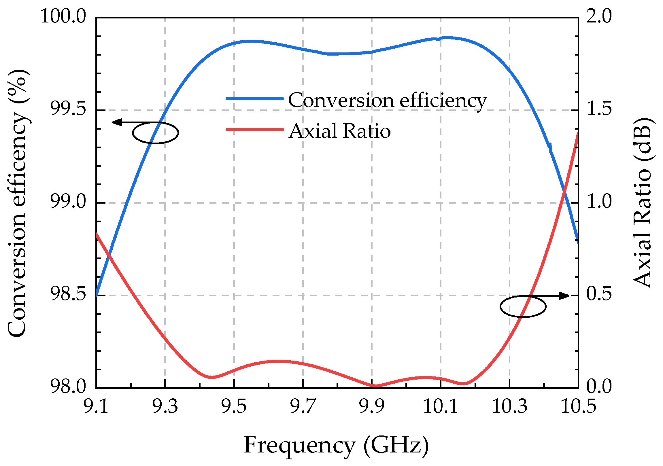
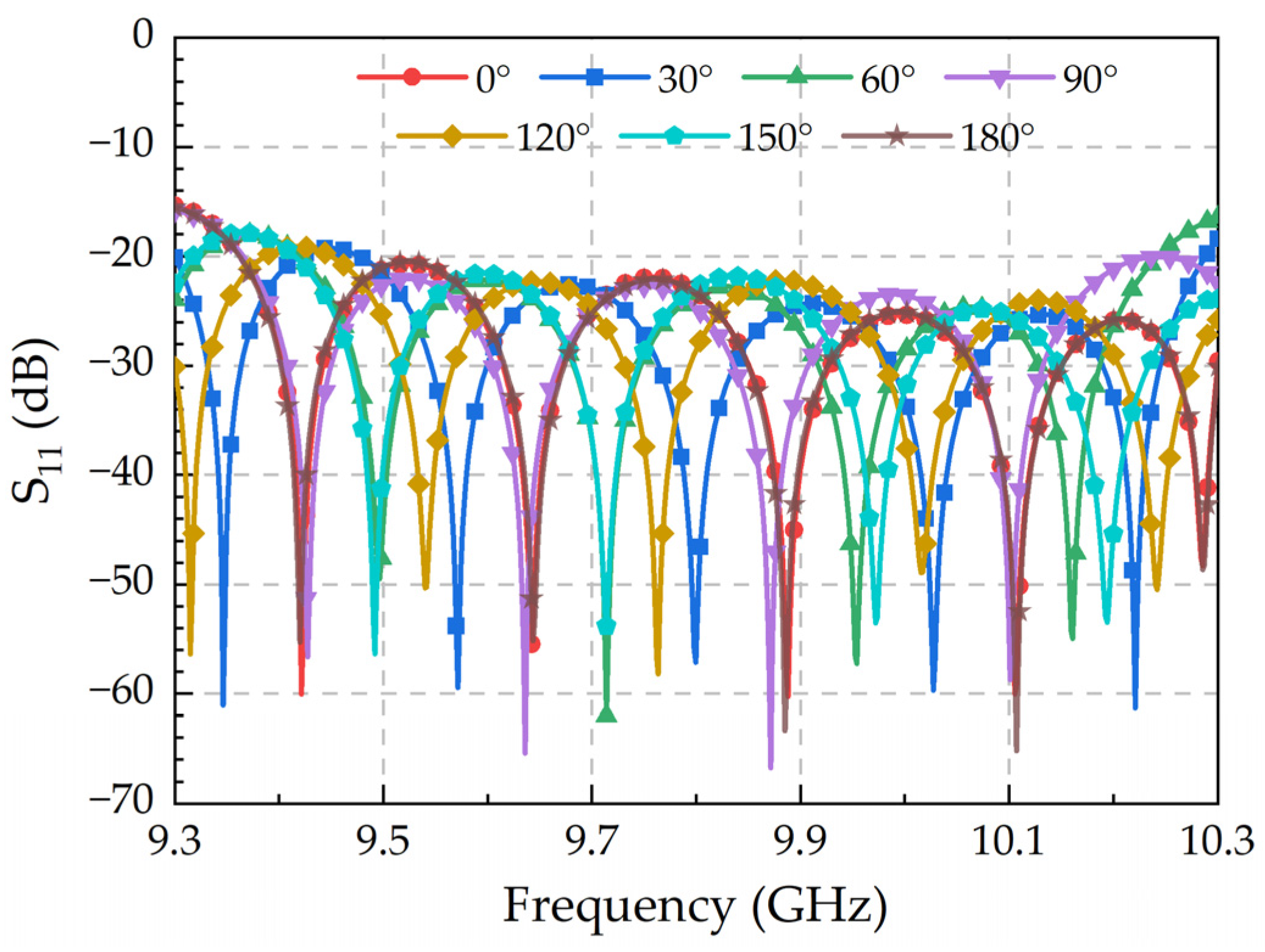
 Figure 11 and 
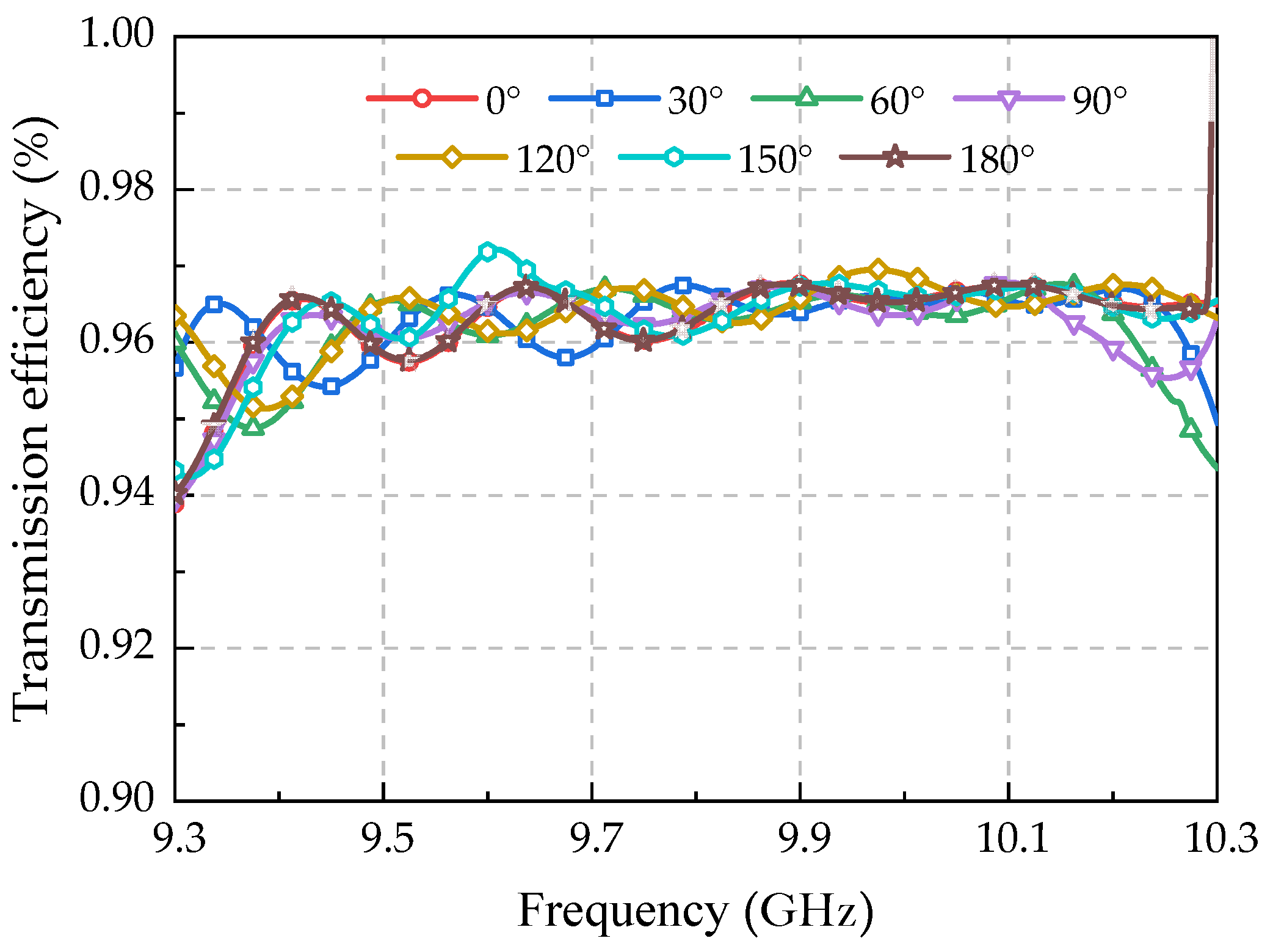
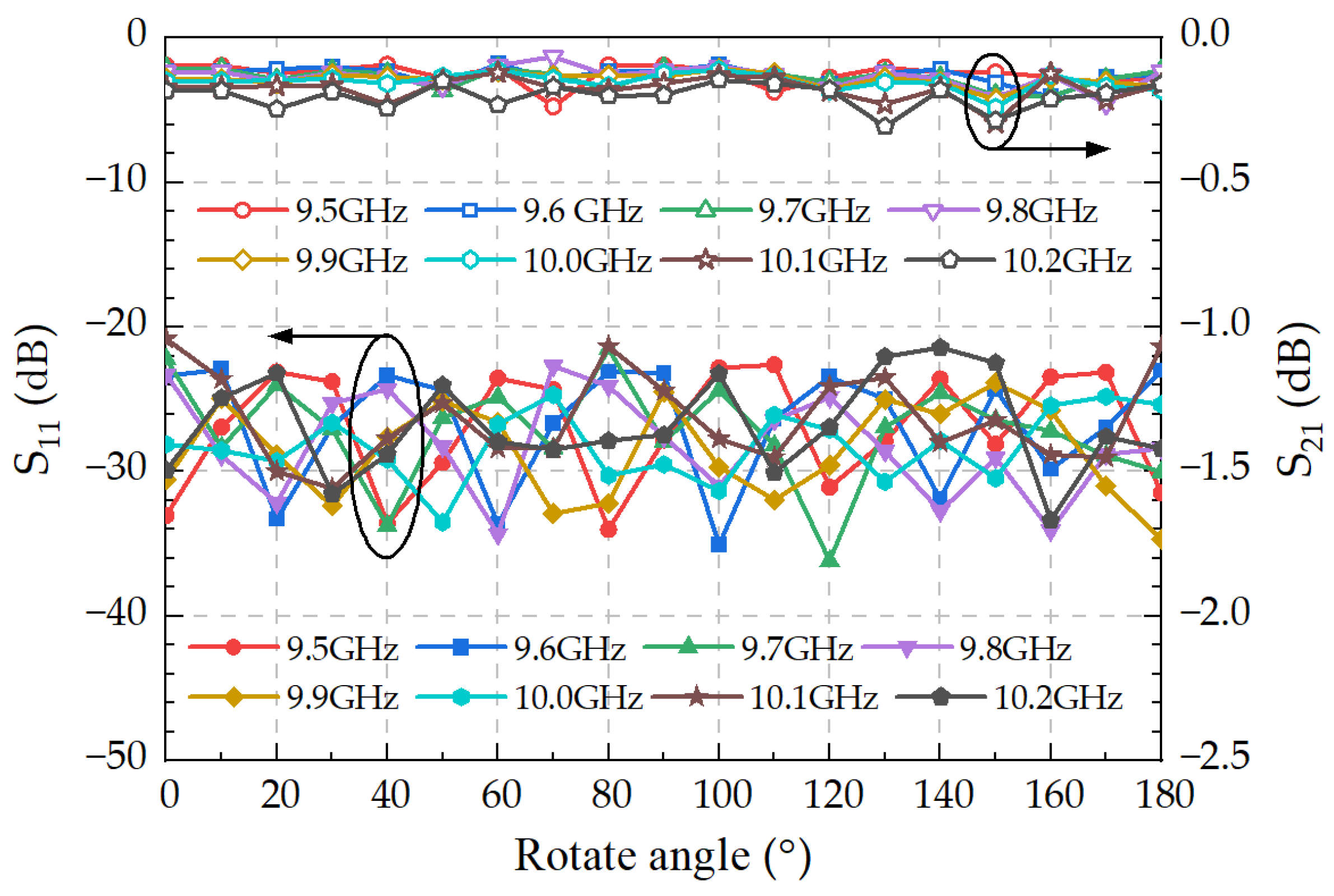
Figure 12 depict the simulation results of the reflection coefficient and transmission efficiency at varying rotation angles, respectively. Notably, the reflection of the phase shifter is less than −20 dB, and the transmission efficiency exceeds 95% (>−0.3 dB) within the frequency range of 9.5–10.2 GHz, indicating that the working frequency band of the phase shifter spans greater than 700 MHz. Furthermore, 
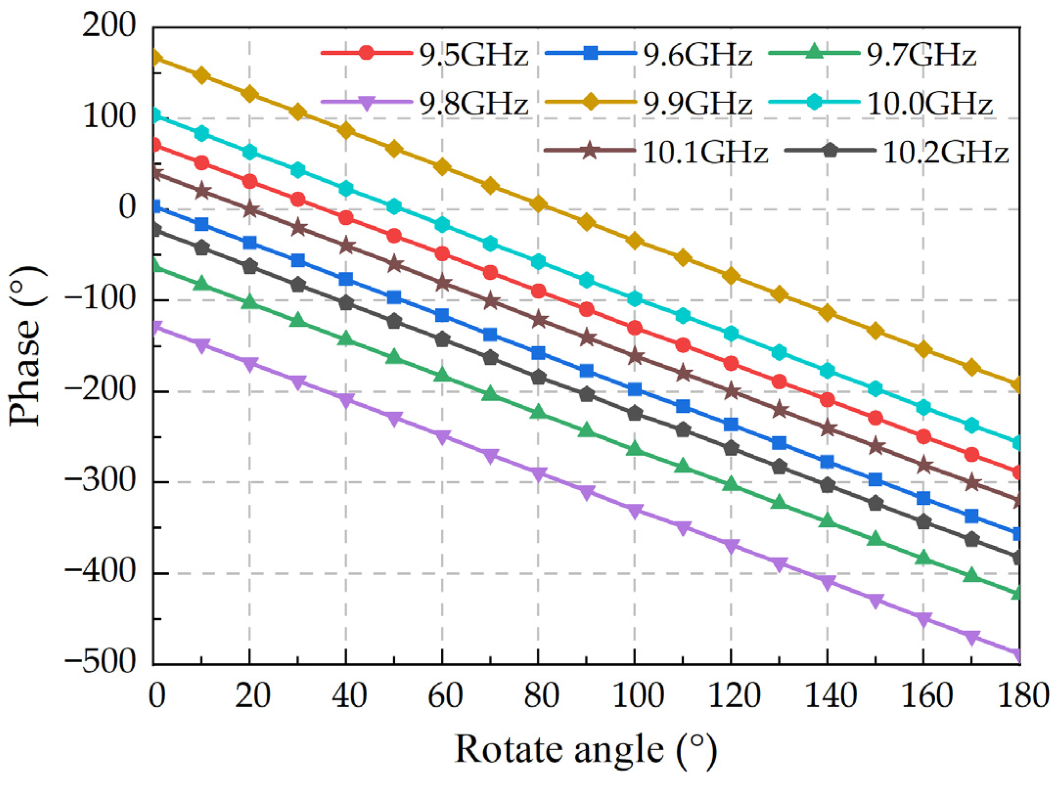
Figure 13 shows the output phase of the phase shifter at varying rotation angles. It can be seen that the phase shifter exhibits an approximately 360° linear phase shift within the aforementioned frequency range as it rotates from 0° to 180°.
Additional research has been conducted on the deviation of the electrical phase shift and the twice mechanical angle at varying rotation angles, and the calculation formula for the phase-shifting deviation is calculated as follows:
error = φ φ 0 2 Δ θ
where φ0 represents the initial phase of the phase shifter when the LH-RHCP mode converter is not rotated, while φ represents the output phase of the phase shifter when the LH-RHCP mode converter is rotated by Δθ.
Figure 14 illustrates the phase-shifting deviation of the phase shifter at different rotation angles. It can be seen that in the frequency range of 9.5–10.2 GHz, the maximum phase-shifting deviation is less than 1.2° during the rotation process from 0° to 180°.
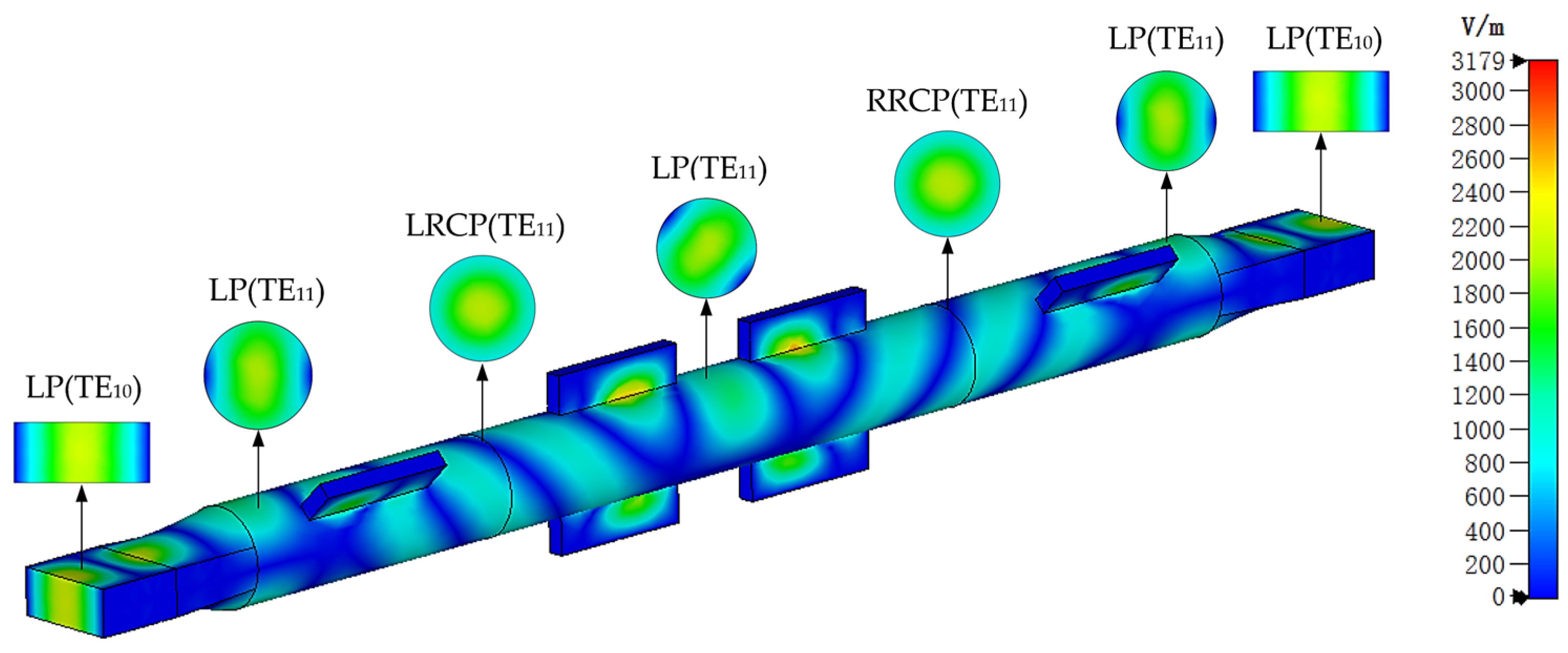
The electric field distribution of the phase shifter is shown in Figure 15. It clearly displays the mode conversion process of the phase shifter. With an input microwave power of 0.5 W, the maximum surface field strength of the phase shifter is 3179 V/m. In HPM applications, phase shifters and other microwave transmission components typically operate under a high-level vacuum condition. Under vacuum conditions, the RF breakdown field strength is approximately 1 MV/cm [18,19]. For assurance, assuming the breakdown field strength is 0.7 MV/cm, the phase shifter has a power-handling capacity larger than 242 MW. Furthermore, the maximum surface field strength of the phase shifter occurs at the intersection of the rectangular groove and the circular waveguide. Hence, implementing a chamfered transition in the intersection further enhances the power-handling capacity of the phase shifter.

5. Experimental Results

To validate the aforementioned phase-shifting principle and design method, a prototype of a phase shifter with a center frequency of 9.8 GHz was manufactured, and its transmission characteristics were tested using an Agilent vector network analyzer (VNA), as shown in Figure 16. Figure 17 presents the measured results of the transmission characteristics of the phase shifter at varying rotation angles. The measured data demonstrate remarkable agreement with the simulation results. Within the frequency range of 9.5–10.2 GHz, the reflectance remains below −20 dB throughout the entire rotation process, while the insertion loss is almost always below 0.3 dB. This indicates that the phase shifter exhibits good stability and transmission efficiency. Finally, Figure 18 illustrates the measured phase characteristics at varying rotation angles. Figure 18 and Figure 13 show the trend of phase variation with rotation angle, but it is worth noting that they show opposite trends. This is due to the different rotation directions of the phase shifter. The measured phase characteristics indicate that the phase shifter is capable of achieving a linear phase adjustment of 360° when rotated by 180° within the frequency range of 9.5–10.2 GHz.

6. Discussion

It is noteworthy that the circular polarizer employed in the phase shifter is realized by incorporating a pair of tilted rectangular grooves in the circular waveguide, which yields a working bandwidth exceeding 700 MHz. For a further extension of the working bandwidth, multiple pairs of tilted 45° rectangular grooves can be employed in the circular polarizer. Simulation results have verified that using two pairs of rectangular grooves is sufficient to achieve a working bandwidth of 1 GHz. However, it is important to consider that the length of the phase shifter will also increase accordingly. Therefore, the choice of the number of rectangular grooves should be made based on the actual requirements.
Table 3 shows the performance comparison of several different phase shifters, which demonstrates that the phase shifter designed in this paper has a wider relative bandwidth and a good transmission performance. Although the phase shifter exhibits obvious advantages in operating bandwidth and transmission efficiency, its physical dimensions are relatively large, measuring about 276 mm (9.0λ, λ is the wavelength of free space). As a result, the phase shifter is restricted to low-frequency HPM applications. In order to meet the requirements of low-frequency applications, the next phase of development involves further optimizing the structure of the phase shifter. This entails conducting research and designing a wideband LHCP/RHCP mode converter without a rectangular-to-circular transition part, as well as developing a more compact wideband circular polarizer structure.

7. Conclusions

This paper presents a high-power rotary waveguide phase shifter based on circular polarizers that is suitable for HPM applications. The phase shifter can achieve a 360° high-precision linear phase shift by rotation, and the phase shift is twice the rotation angle. Through optimized design and simulation of the X-band phase shifter made of aluminum, the results show that the reflection of the phase shifter is less than −20 dB and the insertion loss is below 0.3 dB within the frequency range of 9.5–10.2 GHz. Meanwhile, the maximum phase-shifting deviation is less than 1.2°, and the expected power-handling capacity is up to 242 MW. To validate the phase-shifting principle and design method, a prototype of a phase shifter was manufactured and measured; the experimental results are in good agreement with the simulation results. Accordingly, the phase shifter has broad application prospects in HPM coherent synthesis systems with its advantages of high phase-shifting accuracy, high transmission efficiency, and a simple phase adjustment method.

Author Contributions

Conceptualization, Q.Z. and F.Y.; methodology, Q.Z.; software, M.Y.; validation, Q.Z., F.Y. and M.L.; formal analysis, Q.Z.; investigation, M.Y.; resources, F.Y.; data curation, Z.X.; writing—original draft preparation, Q.Z.; writing—review and editing, Q.Z.; visualization, F.Y.; supervision, Z.X.; project administration, F.Y.; funding acquisition, Q.Z. All authors have read and agreed to the published version of the manuscript.

Funding

This research received no external funding.

Data Availability Statement

No new data were created or analyzed in this study. Data sharing is not applicable to this article.

Conflicts of Interest

The authors declare no conflict of interest.

Abbreviations

Abbreviations used in this paper.
HPMHigh-power microwave
LPLinearly polarized
CPCircularly polarized
LHCPLeft-handed circularly polarized
RHCPRight-handed circularly polarized
LP-LHCPLinearly polarized to left-handed circularly polarized
LH-RHCPLeft-handed to right-handed circularly polarized
LP-RHCPLinearly polarized to right-handed circularly polarized
ARaxial ratio

References

  1. Parker, D.; Zimmermann, D.C. Phased Arrays-Part II: Implementations, Applications, and Future Trends. IEEE Trans. Microw. Theory Tech. 2002, 50, 688–698. [Google Scholar] [CrossRef]
  2. Zhang, Q.; Zhao, X.; Yuan, C.; Zhang, J.; Sun, Y. High-Power Waveguide Phase Shifters for Phased Array Applications. Rev. Sci. Instrum. 2020, 91, 094703. [Google Scholar] [CrossRef] [PubMed]
  3. Guo, L.; Huang, W.; Chang, C.; Li, J.; Liu, Y.; Meng, R. Studies of a Leaky-Wave Phased Array Antenna for High-Power Microwave Applications. IEEE Trans. Plasma Sci. 2016, 44, 2366–2375. [Google Scholar] [CrossRef]
  4. Ghaffar, F.A.; Shamim, A. A Partially Magnetized Ferrite LTCC-Based SIW Phase Shifter for Phased Array Applications. IEEE Trans. Magn. 2015, 51, 4003108. [Google Scholar] [CrossRef]
  5. Deng, G.J.; Huang, W.H.; Li, J.W.; Shao, H.; Guo, L.T.; Xie, S.Y. Effect of Peak Power Enhancement of Ferrite Phase Shifter from Full-Height to Increased-Height Rectangular Waveguide. Rev. Sci. Instrum. 2019, 90, 114705. [Google Scholar] [CrossRef] [PubMed]
  6. Nafe, A.; Shamim, A. An Integrable SIW Phase Shifter in a Partially Magnetized Ferrite LTCC Package. IEEE Trans. Microw. Theory Tech. 2015, 63, 2264–2274. [Google Scholar] [CrossRef] [Green Version]
  7. Parnes, M.; Vendik, O. P-i-n Diode Phase Shifter in Waveguide Structure. Microw. Opt. Technol. Lett. 2015, 57, 1666–1671. [Google Scholar] [CrossRef]
  8. Yin, L.; Yang, P.; Gan, Y.; Yang, F.; Yang, S.; Nie, Z. A Low Cost, Low in-Band RCS Microstrip Phased-Array Antenna with Integrated 2-Bit Phase Shifter. IEEE Trans. Antennas Propag. 2021, 69, 4517–4526. [Google Scholar] [CrossRef]
  9. Guo, L.; Abbosh, A. Phase Shifters with Wide Range of Phase and Ultra-Wideband Performance Using Stub-Loaded Coupled Structure. IEEE Microw. Wireless Compon. Lett. 2014, 24, 167–169. [Google Scholar] [CrossRef]
  10. Romano, P.; Araromi, O.; Rosset, S.; Shea, H.; Perruisseau-Carrier, J. Tunable Millimeter-Wave Phase Shifter Based on Dielectric Elastomer Actuation. Appl. Phys. Lett. 2014, 104, 024104. [Google Scholar] [CrossRef]
  11. Yang, Y.-M.; Yuan, C.-W.; Qian, B.-L. A Novel Phase Shifter for Ku-Band High-Power Microwave Applications. IEEE Trans. Plasma Sci. 2014, 42, 51–54. [Google Scholar] [CrossRef]
  12. Zhuang, Q.; Xiong, Z.; Yan, F.; Yang, M.; Liu, Y. A Novel T-Shaped High-Power Waveguide Phase Shifter with Continuous Linear Phase Adjustment. Rev. Sci. Instrum. 2023, 94, 034704. [Google Scholar] [CrossRef] [PubMed]
  13. Chang, C.; Guo, L.; Tantawi, S.G.; Liu, Y.; Li, J.; Chen, C.; Huang, W. A New Compact High-Power Microwave Phase Shifter. IEEE Trans. Microw. Theory Tech. 2015, 63, 1875–1882. [Google Scholar] [CrossRef]
  14. Chan, K.-L.; Judah, S.R. Modal Analysis at the Junction Formed by a Circular or an Elliptic Waveguide and a Translated and Rotated Elliptic Waveguide. IEE Proc. Microw. Antennas Propag. 1998, 145, 501. [Google Scholar] [CrossRef]
  15. Yuan, C.-W.; Yu, L.-Z.; Zhang, Q.; Xu, L.; Zhao, X.-H. A Novel High-Power Waveguide Phase Shifter with Continuous Linear Phase Adjustment. Rev. Sci. Instrum. 2020, 91, 114704. [Google Scholar] [CrossRef] [PubMed]
  16. Zhao, X.-L.; Yuan, C.-W.; Liu, L.; Peng, S.-R.; Bai, Z.; Cai, D. GW TEM-Mode Phase Shifter for High-Power Microwave Applications. IEEE Trans. Plasma Sci. 2016, 44, 268–272. [Google Scholar] [CrossRef]
  17. Peng, S.; Yuan, C.; Zhong, H.; Fan, Y. Design and Experiment of a Cross-Shaped Mode Converter for High-Power Microwave Applications. Rev. Sci. Instrum. 2013, 84, 124703. [Google Scholar] [CrossRef] [PubMed]
  18. Shao, H.; Hu, Y.; Chang, C.; Guo, L. A High-Power Microwave Circular Polarizer and Its Application on Phase Shifter. Rev. Sci. Instrum. 2016, 87, 044701. [Google Scholar] [CrossRef] [PubMed]
  19. Gong, H.; Yuan, C.; Zhao, X.; Zhang, Q. A Novel TM01-TE01 High-Power Microwave Mode Converter. AIP Adv. 2019, 9, 045114. [Google Scholar] [CrossRef] [Green Version]
  20. Sun, Y.; He, J.; Yuan, C.; Zhang, Q.; Dang, F. Design and Experimental Demonstration of a TEM-TE 10 Phase Shifter for High-Power Microwave Applications. Rev. Sci. Instrum. 2019, 90, 014709. [Google Scholar] [CrossRef] [PubMed]
Figure 1. Structure of the novel high-power rotary waveguide phase shifter.
Electronics 12 02963 g001
Figure 2. Schematic diagram of the structure of the circular polarizer.
Electronics 12 02963 g002
Figure 3. ex-ey and e1-e2 coordinate system.
Electronics 12 02963 g003
Figure 4. Schematic diagram of the structure of the LP-LHCP mode converter.
Electronics 12 02963 g004
Figure 5. Magnitude and phase difference of S parameters for the LP-LHCP mode converter.
Electronics 12 02963 g005
Figure 6. Conversion efficiency and axial ratio of the LP-LHCP mode converter.
Electronics 12 02963 g006
Figure 7. Schematic diagram of the structure of the LH-RHCP mode converter.
Electronics 12 02963 g007
Figure 8. Magnitude and phase difference of S parameters for the LH-RHCP mode converter.
Electronics 12 02963 g008
Figure 9. Conversion efficiency and axial ratio of the LH-RHCP mode converter.
Electronics 12 02963 g009
Figure 10. Schematic diagram of the structure of the LP-RHCP mode converter.
Electronics 12 02963 g010
Figure 11. Conversion efficiency of the phase shifter.
Electronics 12 02963 g011
Figure 12. Transmission efficiency of the phase shifter.
Electronics 12 02963 g012
Figure 13. Output phase of the phase shifter at varying rotation angles.
Electronics 12 02963 g013
Figure 14. Phase-shifting deviation of the phase shifter at varying rotation angles.
Electronics 12 02963 g014
Figure 15. Electric field distribution of the phase shifter.
Electronics 12 02963 g015
Figure 16. Photographs of the phase shifter prototype and the measurement setup: (a) phase shifter prototype; (b) measurement setup.
Electronics 12 02963 g016
Figure 17. Transmission characteristics of the phase shifter at varying rotation angles.
Electronics 12 02963 g017
Figure 18. Phase characteristics of the phase shifter at varying rotation angles.
Electronics 12 02963 g018
Table 1. Specific dimensions of the LP-LHCP mode converter (Unit in mm).
ParametersValueParametersValue
l023h18.1
r010.8t05
d132.7e02
w13.55
Table 2. Specific dimensions of the LH-RHCP mode converter (unit in mm).
ParametersValueParametersValue
d232.7t220.6
w23.7t05
h28.2e02
Table 3. Comparison of several different phase shifters.
ReferencePhase Modulation TypesFrequency (GHz)Bandwidth (%)Insertion Loss (dB)Phase Shift (°)
[13]
2015
push–pull9.3250.430.15360
[2]
2020
push–pull9.5-0.3360
[15]
2020
rotary8.42.40.81360
[16]
2016
rotary1.79-0.06360
[20]
2019
rotary1.570.960.55360
This workrotary9.87.140.3360
Disclaimer/Publisher’s Note: The statements, opinions and data contained in all publications are solely those of the individual author(s) and contributor(s) and not of MDPI and/or the editor(s). MDPI and/or the editor(s) disclaim responsibility for any injury to people or property resulting from any ideas, methods, instructions or products referred to in the content.

