Communication

A Semi-Elliptical UWB Folded Dipole Antenna

1
Institut d’Electronique et des Technologies du numeRique (IETR), Université de Rennes, 35000 Rennes, France
2
THALES SIX GTS France, 49309 Cholet, France
*
Author to whom correspondence should be addressed.
Electronics 2023, 12(13), 2788; https://doi.org/10.3390/electronics12132788
Submission received: 28 April 2023 / Revised: 19 June 2023 / Accepted: 22 June 2023 / Published: 24 June 2023
(This article belongs to the Special Issue Antennas and Microwave/Millimeter-Wave Applications)

Abstract

:
In this paper, a novel structure of a semi-elliptical folded dipole for ultra-wideband (UWB) receiving applications is discussed. This proposed antenna has a directive radiation pattern resulting in a high gain over the bandwidth. The design uses a planar technology including a microstrip line to slot line transition and optimized curves to obtain a measured impedance bandwidth of 2.3–26 GHz with the condition of S11 < −6 dB (level accepted for receiving antenna) and meets S11 < −10 dB in several bands. Additionally, the simulated gain ranges from 5 dBi to 9.5 dBi across the entire bandwidth with an efficiency of at least 75%. This antenna model offers a reconfiguration capability. The symmetrical feeding used in this antenna creates the directive behavior. Characteristics of this semi-elliptical folded dipole antenna make it suitable for modern wireless communications, such as 5 G around 3.5 GHz, and easy to integrate in antenna arrays (MIMO systems). The four ports of the antenna also make it a candidate for radiation pattern reconfigurability applications reducing in this way the number of elements in network antennas.

1. Introduction

Following the Federal Communications Commission’s (FCC) allocation of the frequency band 3.1 GHz to 10.6 GHz for commercial communication applications in 2002 [1], ultra-wideband (UWB) systems have emerged as a significant area of interest in the electronics industry. There are plenty of applications in diverse domains, such as telecommunications, medical, space and military fields [2,3]. Various types of antennas, such as horns, log-periodic antennas, conical antennas, planar monopoles and dipoles, have been extensively studied to achieve wide bandwidths [4,5,6,7,8]. These antennas offer optimized transitions from feeding to free space.
Printed antennas are widely chosen in ultra-wideband applications due to their numerous advantages, including small size, low cost, high radiation efficiency and simple design and production. To meet the specific requirements of different applications, it is common to employ different modifications of geometry. Typically, square, cylindrical, elliptical, or even fractal shapes are good examples to extend the impedance bandwidth of monopole and dipoles antennas [9,10,11,12,13]. Another technique for modifying antenna impedance involves folding the structure over a ground plane, allowing for optimization of the bent structure to yield improved outcomes. This folding technique can also control the orientation of surface currents [14] and enable control over radiation direction. Recent studies on planar folded dipoles have achieved bandwidths ranging from one to several octaves [15,16,17]. In those examples, only microstrip feed lines have been used. This solution is the simplest way to feed an antenna with an asymmetrical wave. However, these examples of folded antennas do not offer any reconfiguration possibilities.
In this study, an elliptical folded dipole antenna design for Ultra-Wide Band (UWB) applications is discussed. The optimized folded monopole shape is used as the basis for the antenna design, and previous studies [18,19,20,21] have examined the folding of thick monopoles and dipoles over a ground plane to enlarge the impedance bandwidth. Parameters such as the thickness of the fed and the folded wires were according to [18,19,20,21]. Stabilization of the radiation pattern of the antenna is achieved by adding a second strand with vertical symmetry. This idea is in opposition to the common folded dipole which includes a horizontal symmetry. It converts the monopole structure into a dipole one. The proposed antenna has four ports which offers reconfigurability. We chose to connect two of them to the ground. Depending on the choice of the feed, symmetrical or asymmetrical, the radiation behavior is modified. Feeding the antenna with a symmetric (0°/180°) wave using a microstrip line to slot line transition [22,23,24] results in a directive radiation pattern. In this paper, different configurations are presented but only the directive version has been fully realized and measured. Applications related to wireless communications such as 5 G (3.5 GHz bands) or antenna arrays requiring directive radiating elements are considered (indoor/outdoor communications). The proposed antenna exhibits an impedance bandwidth of 2.3 GHz to 26 GHz+ when S11 < −6 dB, with a maximum gain of 9.5 dBi at 6.6 GHz. For more common communications applications, this antenna achieves the S11 < −10 dB condition in the bands 3.3–8 GHz, 9.8–12.6 GHz and 13.1–26 GHz. However, at high frequencies (>12 GHz), the directional behavior of this folded dipole antenna is not fully verified. A significant cross-polarization and lateral radiation are observed.

2. Folded Structures and Feeding

2.1. Large Folded Monopole

A large folded monopole of λ/4 in length is comparable with a conventional monopole in many points. In particular, the radiation pattern has a toroidal shape at the resonance frequency fr (Figure 1a). The monopole can be bent to affect this radiation. In Figure 1b, bending the antenna over a ground plane results in a main beam with a significant steering at f = 2 fr, while the pattern is still toroidal at lower frequencies. At f = 5 fr, the null on the axis of the structure is now replaced by a maximum of radiation. This is a technique to obtain a directive antenna in a precise direction at a specific frequency.

2.2. Large Folded Dipole and Symmetrical Feeding

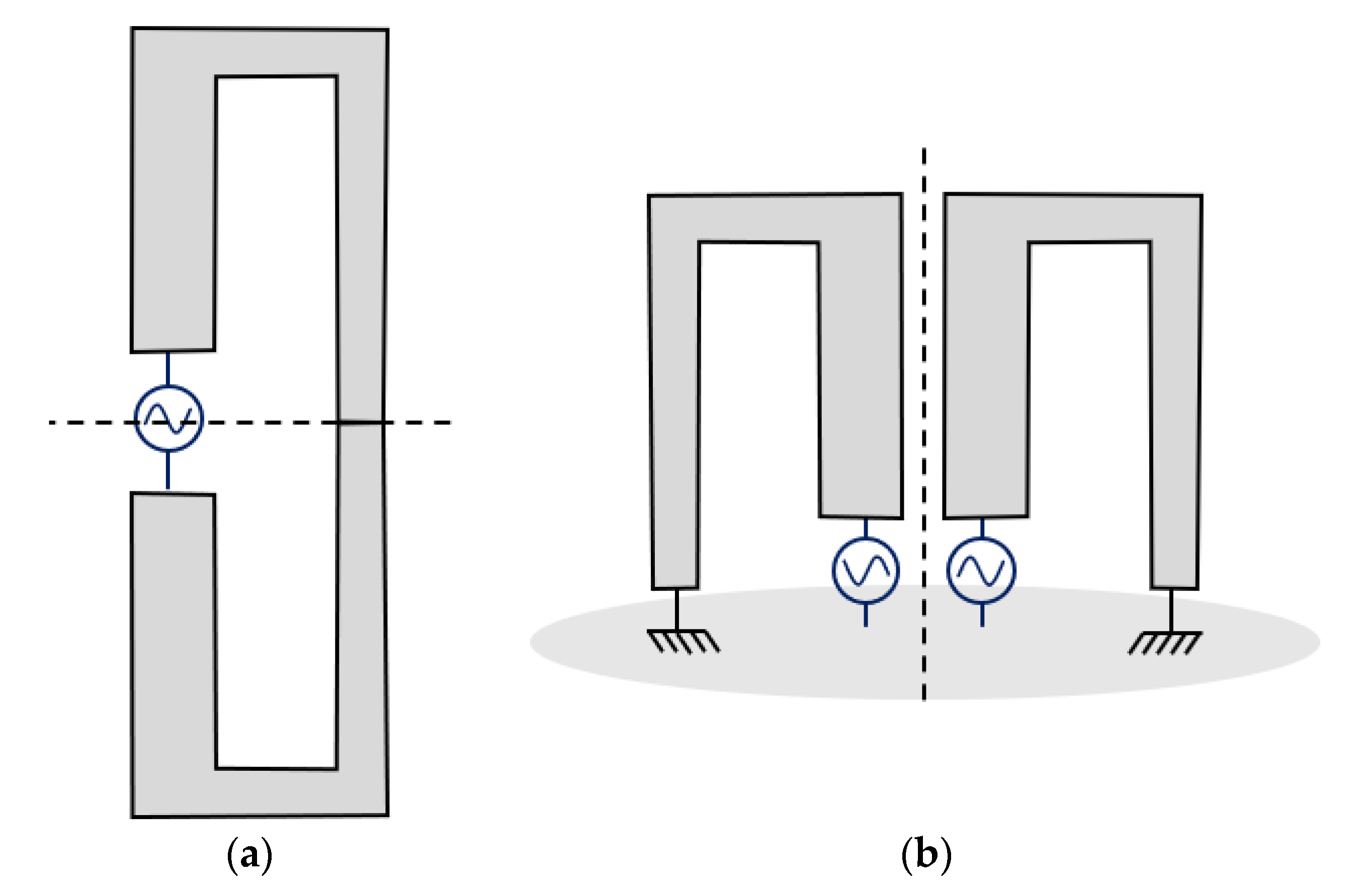
The classic toroidal radiation pattern of the monopole and dipole can be restored throughout the frequency range fr < f < 5 fr by making the structure symmetrical. The conventional folded dipole is designed along a horizontal plane of symmetry, as shown in Figure 2a, but in this paper, we propose to implement this symmetry along a vertical axis and keep the horizontal ground plane (Figure 2b).
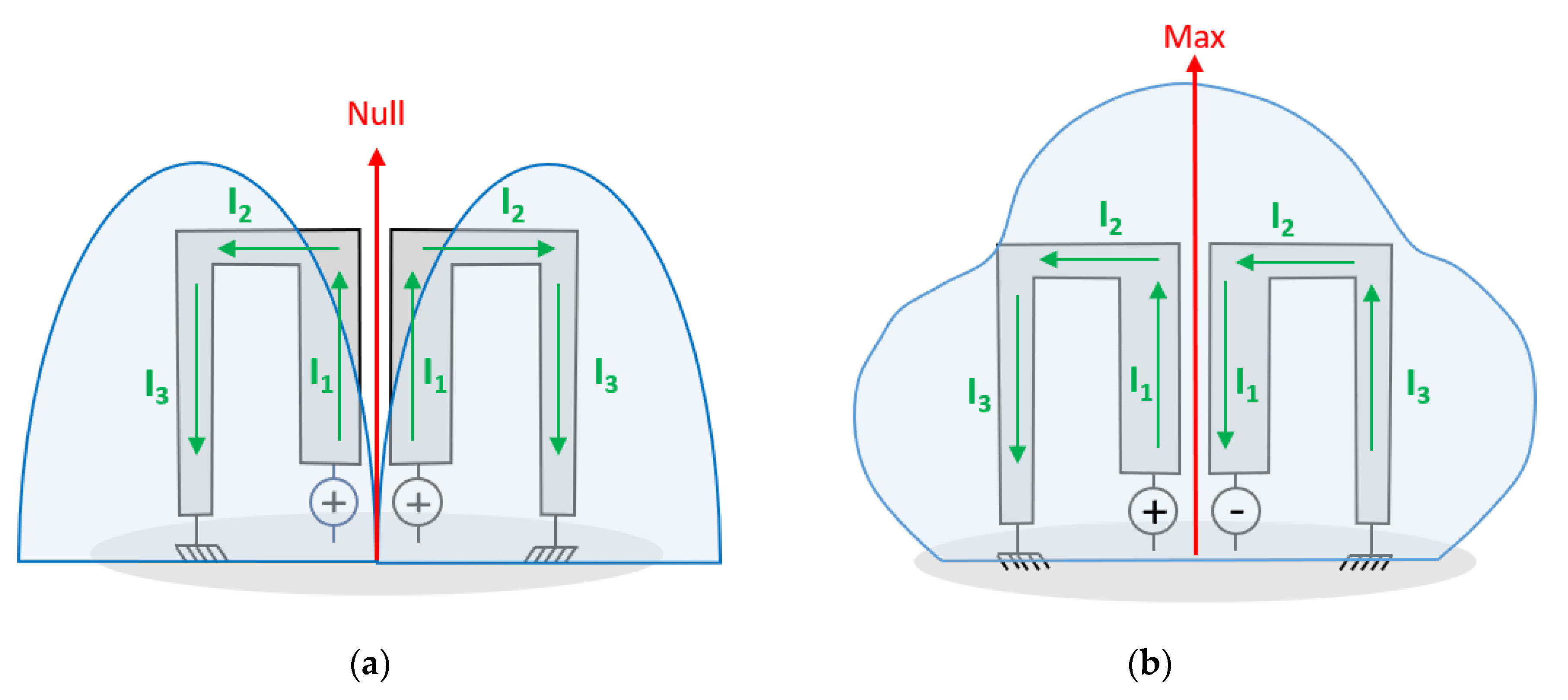
Consequently, when both arms of the antenna are excited with an asymmetrical wave (unbalanced wave), no radiation is observed along the axis of symmetry of the dipole (Figure 3a). We retrieve the typical dipole pattern. However, to obtain a directive behavior, a 180° phase shift is applied to the two arms. As a result, a maximum radiation is now observed along the axis of symmetry in the same frequency range fr < f < 5 fr. By analyzing the electrical currents, we observe that in the case of an asymmetrical feeding, the currents I2 on the two arms of the antenna are opposite. This causes a null of radiation in the axis of the antenna (Figure 3a). However, with a symmetrical feeding (Figure 3b), these two currents add up, which explains the maximum of energy in the axis of the dipole. This maximum is located in the vertical axis because the value of the phase shift is 180°. It is possible that other values such as 90° (or −90°) could redirect this maximum on the right horizontal axis (or left horizontal axis). In other words, using a 90°/−90° coupling circuit, diodes circuits, or even a switch, this antenna design can be seen as a reconfigurable antenna and can still have a directive radiation pattern as mentioned in Figure 4a and b. Otherwise, this behavior is only valid on a narrow band which depends mainly on the antenna height.
This paper only reports on the directive version with a 180° phase difference power supply, since it offers a stable directional behavior over a larger frequency range than the monopole versions. However, work on the reconfigurability aspect of this folded antenna (switch, pin diode, coupling circuit) is in progress, also the beam direction can change with the feed phase difference which could be the subject of a future communication.

3. Design and Simulation

3.1. Semi-Elliptical Monopole to Dipole Design

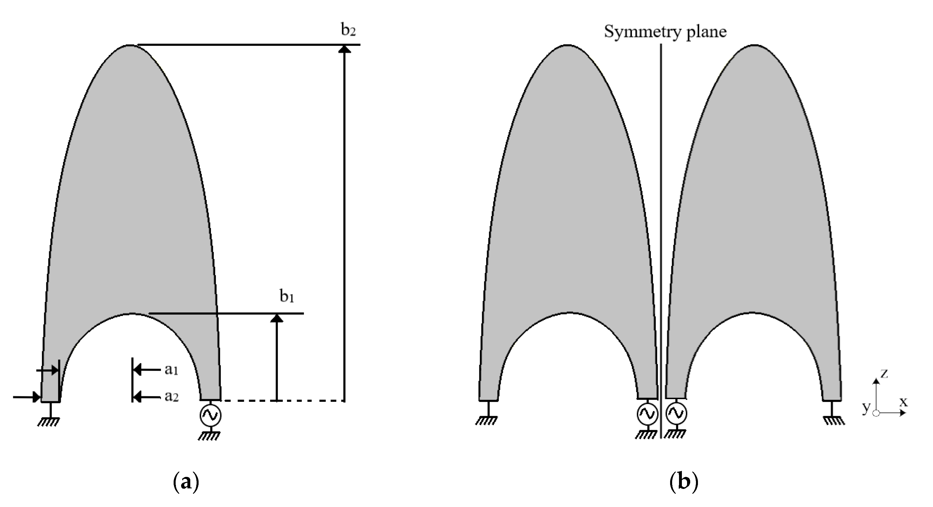
Earlier in the text, we discussed monopoles and dipoles in three dimensions (thick monopoles and dipoles). However, in this paper, we focus only on optimizing planar structures due to their simplified production process and their satisfying performance in terms of matching and radiation. The shape of a semi-elliptical folded monopole antenna that conforms to the principles outlined in the preceding paragraphs, matched to 150 Ω, is shown in Figure 5a. This bending is made of one semi-ellipse and a semi-ellipse hollow. These shapes were chosen because they are known to offer wide bandwidths. The ellipse that defines the outer line has a 0.6 elliptical ratio. The planar structure stands over a ground plane and ends in a short circuit. Various elliptical curves and thicknesses of the monopole were investigated, and the optimal values are outlined in Table 1. The height b2 and the width of the outer ellipse are the dimensions that will mainly define the low frequency of the impedance bandwidth. The inner elliptical trough (hollow), defined by the dimensions a1 and b1, stabilizes the low frequency behavior by changing the current distribution. The currents located on the right edge of the design (Figure 5a) increase with the size of the hollow. To form a dipole, we simply add the symmetrical shape about a vertical plane, as illustrated in Figure 5b. Two of the four ports are grounded, while the two others are connected to the feeding circuit. The gap (g) between the two strands is optimized and produces a 50 Ω matched access. The type of feeding, whether asymmetrical or symmetrical, determines whether it is a null or maximum radiation.
The final design of the folded dipole, obtained by the approach explained in Section 2, is similar to a Vivaldi antenna. The common tapered shape of these two antennas allows a very wide band matching.
In other words, as explained in Section 2, the phase shift means that the antenna’s maximum radiation is off-point. The radiation of several simulated configurations is shown in Figure 6 in the Oxz plane. The case of an in-phase feeding on both wires (0–0°), implies radiation identical to that of a dipole. This behavior is broadband. If we choose a phase shift between 0° and 180°, then we obtain beam steering. In the presented results, at the lowest frequency where the antenna is well matched (1.6 GHz), the steering is around 90°. As the phase shift increases, radiation at 0° appears until it is in the majority when the feed is symmetrical (0–180°). As mentioned earlier, only the directional behavior of the model fed by a 0–180° (or 0–0°) wave is valid over a wide band.

3.2. Microstrip Line to Slot Line Transition

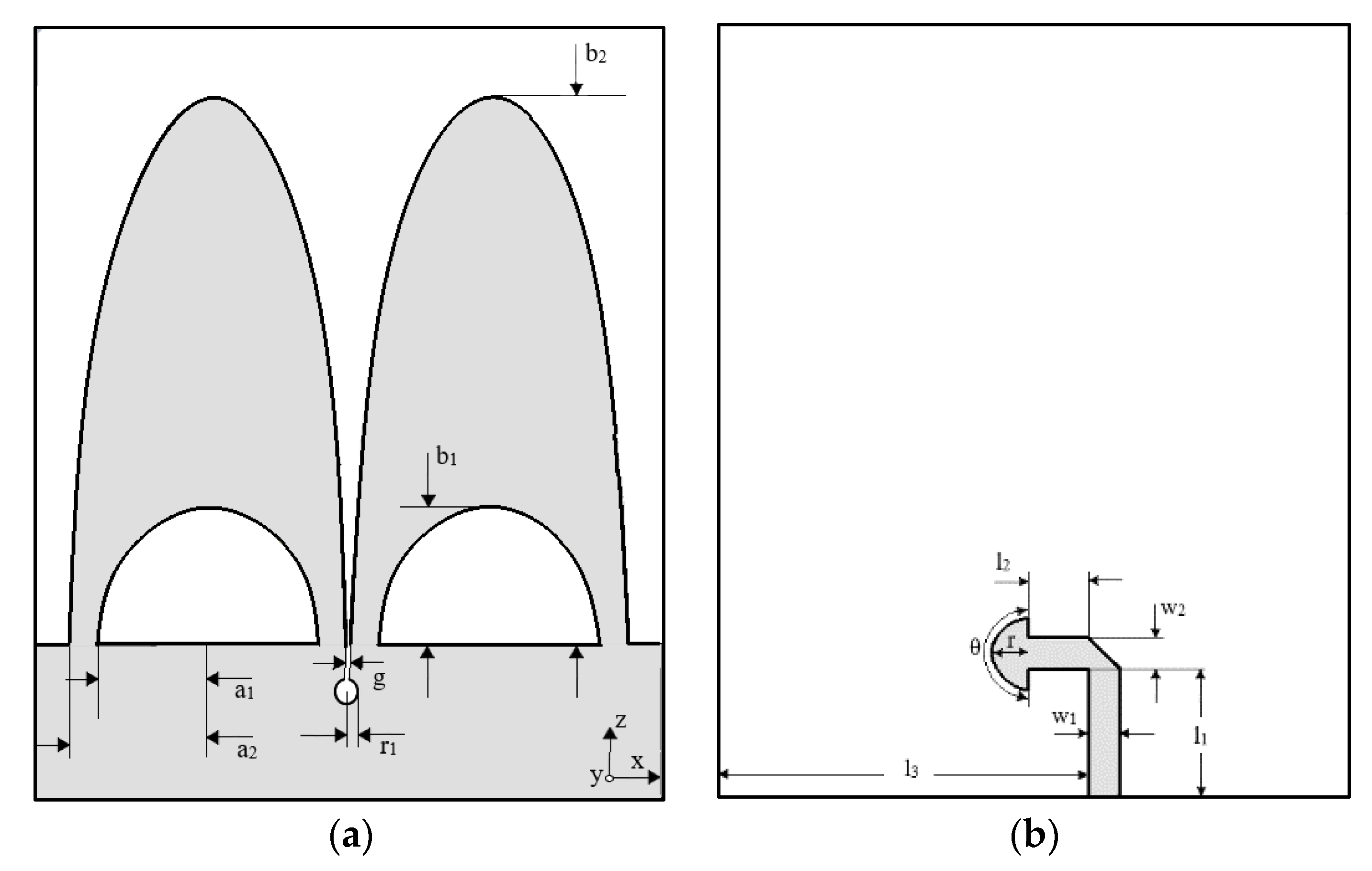
To obtain a maximum radiation in the z-axis, a solution is to feed the two strands of the dipole with a symmetrical wave. In other words, a 180° phase shift feeding circuit must be attached at the bottom of the structure. A proposed method is to feed the antenna using a 50 Ω microstrip line that terminates on an open circuit stub. This line excites the slot between the two arms of the dipole, as depicted in Figure 7b. The difference of potential at these two points of the line results in the creation of a voltage between the two strands, which means that the current is in opposition. However, the transition is a crucial factor in limiting the impedance bandwidth of this type of structure and therefore requires optimization.
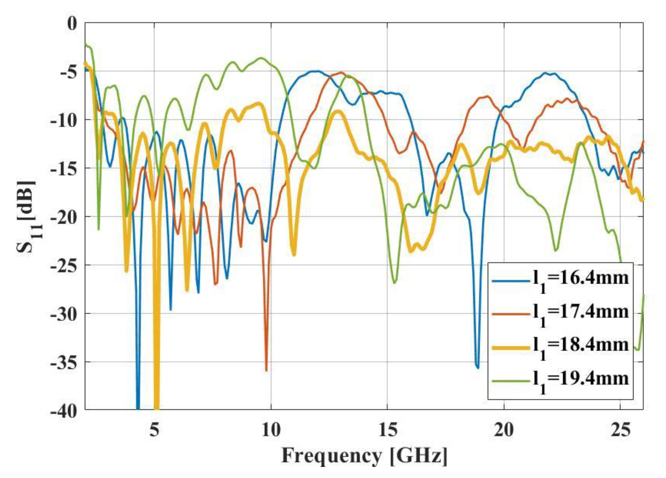
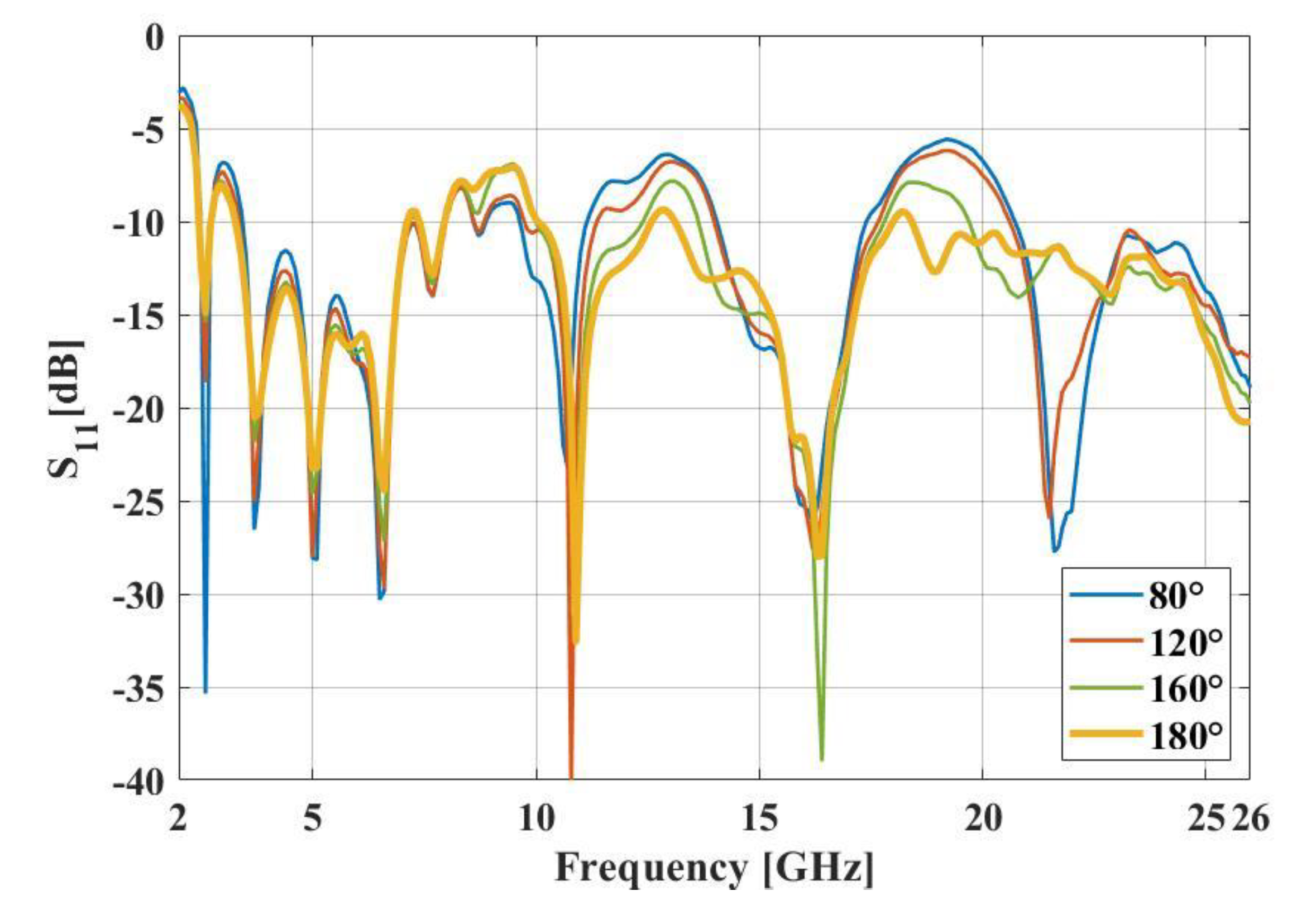
A parametric study on various design parameters of the transition is performed to maximize the frequency range of the antenna. In Figure 8, different l1 lengths are under study. This length impacts the stub position on the slot which changes the impedance matching. Several options are available, depending on the frequency range required. Figure 9 shows the reflection coefficient of a few stub angles (θ). The wider the angle is, the more the S11 is improved, except for the 8–10 GHz frequency range. By combining those results with other minor parametric simulations, we determine the optimized parameters. For example, in this semi-elliptical folded dipole, the combination l1 = 18.4 mm and θ = 180° gave us the best results so far on the whole 2.3–26 GHz frequency range. A1 and b1 are the dimensions (height and width) of the inner semi-ellipse when a2 and b2 are the ones of the outer semi-ellipse.

4. Simulation and Measurement

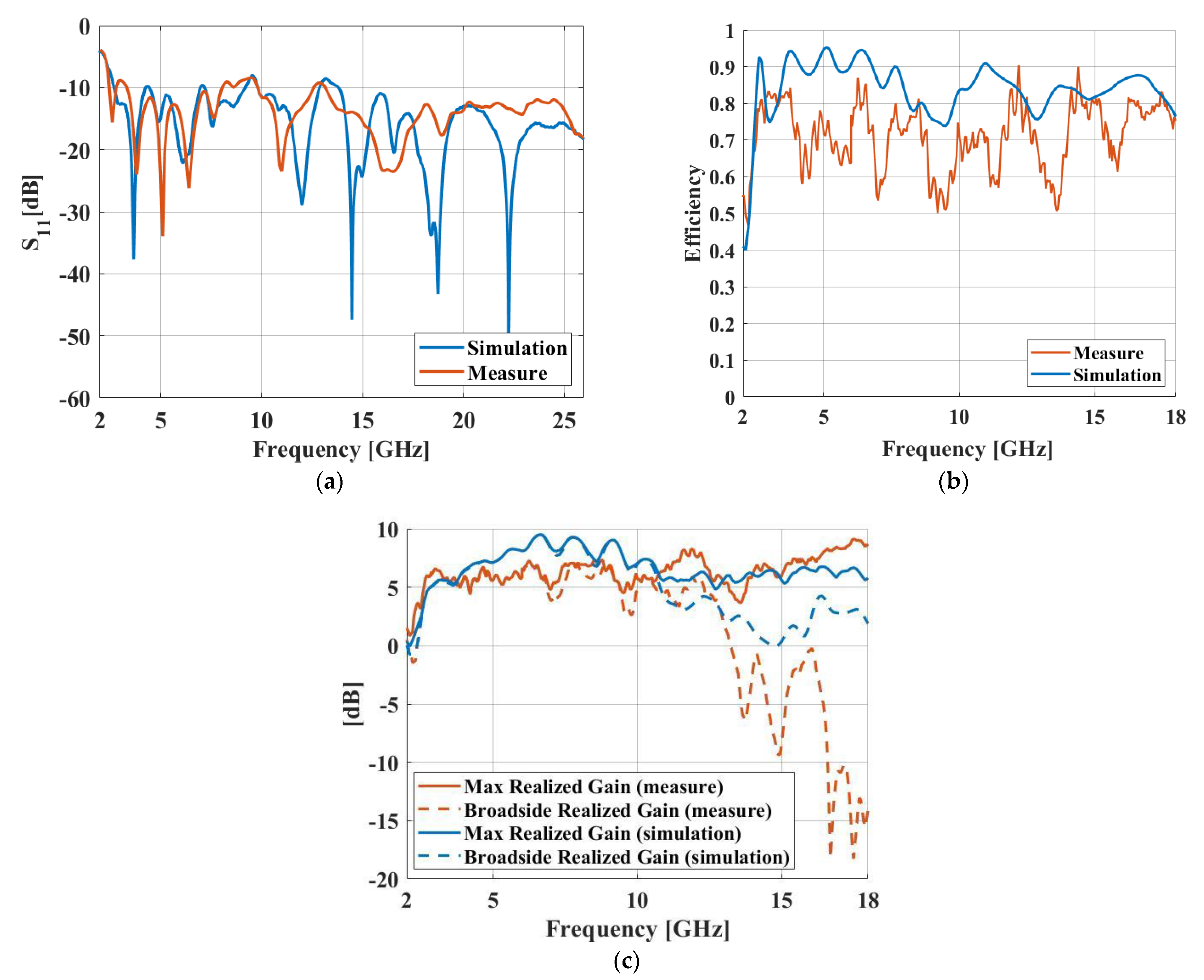
The performance of the semi-elliptical folded dipole antenna, shown in Figure 7, is optimized and simulated using CST Studio Suite. All the parameter values are detailed in Table 1. The substrate used on this antenna design is Rodger R4003C (εr = 3.38, h = 1.52 mm). Figure 10 depicts the prototype of the semi-elliptical folded dipole. The reflection coefficient of the structure is illustrated in Figure 11a. The semi-elliptical dipole has an impedance bandwidth of 2.3 GHz to 25 GHz under the condition of S11 < −6 dB, making it suitable for reception purposes. However, for more restrictive applications, the presented model meets the S11 < −10 dB condition over several bands, including 3.3–8 GHz, 9.8–12.6 GHz and 13.1–26 GHz.
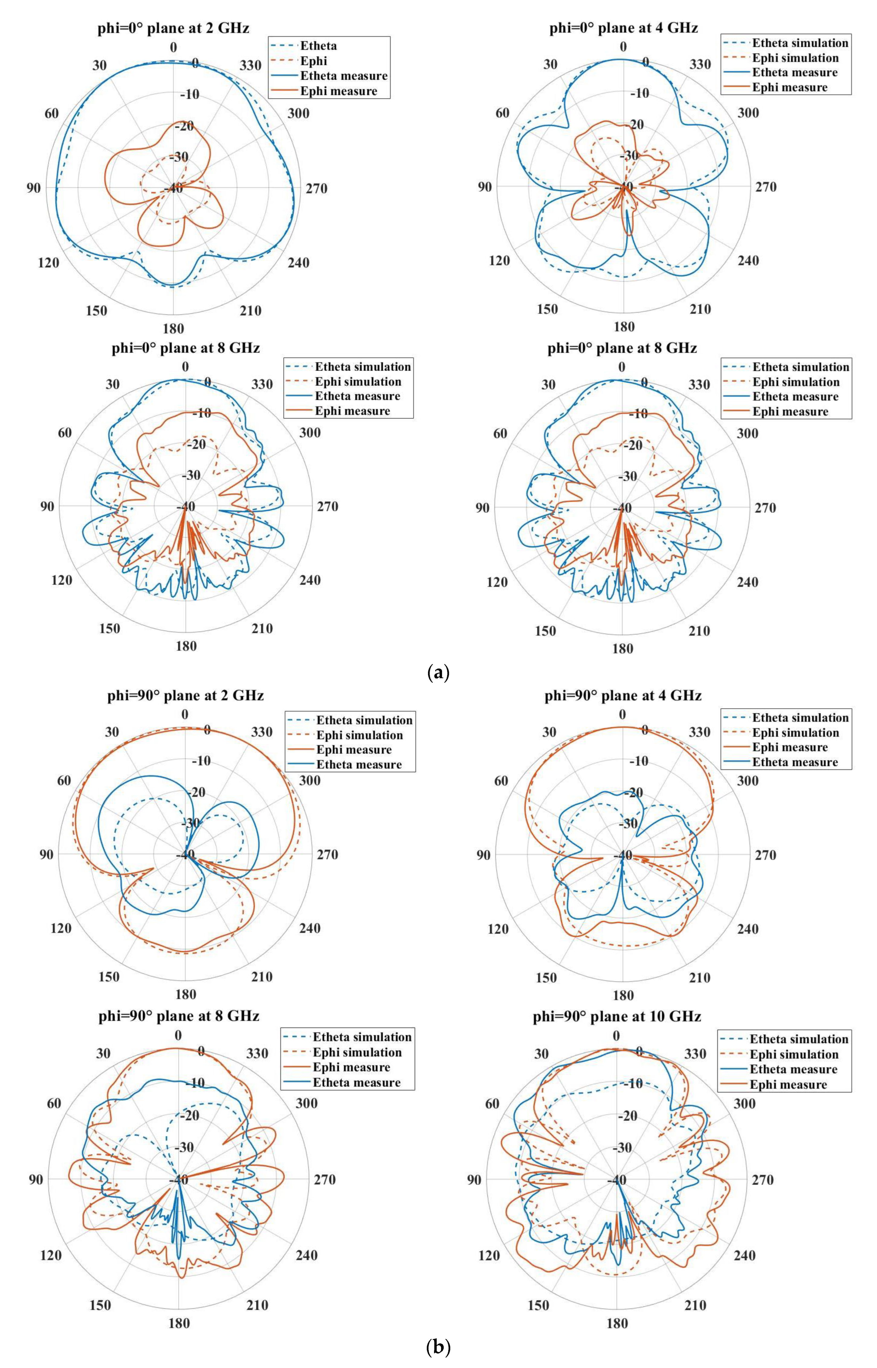
The simulation results for the radiation and total efficiencies of the dipole antenna are presented in Figure 11b. The total efficiency is greater than 75% across the entire bandwidth starting at 2.3 GHz. The proposed structure has directional radiation, resulting in a high maximum gain of 9.5 dBi at 6.6 GHz (Figure 11c), located in the z-axis (broadside). However, above 12 GHz, the maximum radiation is no longer in this direction, and the steering of the main beam and high cross-polarization are observed but not shown in this paper. In this way, broadband radiation behavior is achieved up to 12 GHz. However, for applications that do not require directional radiation (IOT, UWB impulse systems), where the gain remains high, the semi-elliptical folded dipole antenna may be perfectly suitable above 12 GHz. Simulated radiation patterns showing the directional behavior in the 2–10 GHz band are mentioned in Figure 12.
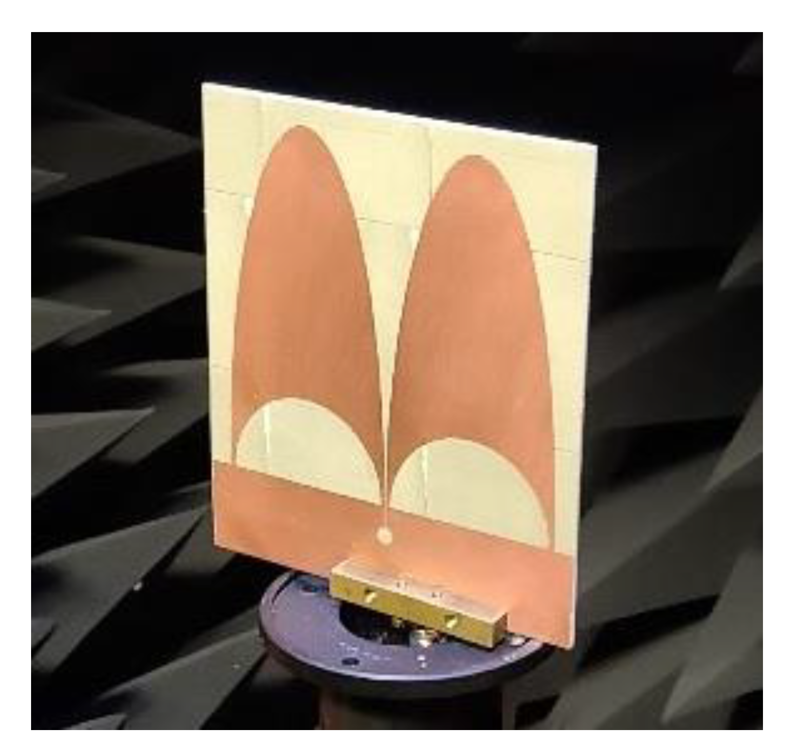
The prototype of the elliptical folded dipole antenna is presented in Figure 13 and has been measured with an MVG—StarLab anechoic chamber. The simulation and measurement results show good agreement. The measured and simulated reflection coefficients are compared in Figure 11a. The measured impedance bandwidth is observed to be 2.3–26 GHz with a condition of S11 < −6 dB. The antenna satisfies the S11 < −10 dB requirement over several bands, including 3.3–8 GHz, 9.8–12.6 GHz and 13.2–26 GHz, similar to the simulation results. The measurement environment (connector, mechanical support, substrate…) used during measurements can explain the differences with simulation results at higher frequencies. Perhaps a connector model could also be considered during the simulation process to improve the reliability of results.
Due to the limitations of the anechoic chamber and software treatments, the efficiency is not as precise as the simulation and has consequences on the measured gain. The peak values vary from 2.9 to 8.2 dBi in the 2.3–12 GHz band. Above 12 GHz, the main beam is no longer in the broadside (z-axis) and causes a diminution of the gain in this direction such as in simulation. The measured radiation patterns show a close resemblance to the simulated ones, with the exception of higher cross-polarization values.
The radiation patterns demonstrate a directive behavior along the dipole axis (at theta = 0°) up to a certain frequency, as observed in the curves. However, above 12 GHz, this radiation becomes more unstable and challenging to characterize. Maybe using an even better connector could solve a part of the difference between simulations and measure above 12 GHz.
Table 2 shows that the proposed antenna provides good impedance bandwidth improvement over other folded dipole antennas [16,17,21]. Compared to other directive solutions such as tapered slots or Vivaldi antennas, the proposed design has the advantage of being reconfigurable thanks to a proper phase-shifting feeding circuit (coupling circuits, diode, switch…).

5. Discussion and Conclusions

In this study, a semi-elliptical folded dipole antenna with ultra-wideband (UWB) characteristics was investigated. Thanks to an optimized dipole shape and a transition between the microstrip line and slot line, we obtain an impedance bandwidth over 167% (2.3–26 GHz) under the condition of S11 < −6 dB. This bandwidth is really wide compared to recent folded dipoles mentioned in this work. The proposed structure offers possibilities of reconfigurability through different feeding phase configurations. The study focused on the circuits that can allow such feeding, so some have not been discussed in this paper. Only the microstrip line to slot line transition, which produces a 180° phase shift feeding, has been studied here. A publication concerning only the reconfigurable aspect of the structure is envisaged. The dipole structure with a symmetrical feeding creates a directive radiation pattern. Both simulation and measurement results indicated that feeding the antenna symmetrically led to maximum gain in the broadside direction. However, cross-polarization increased at higher frequencies. The planar technology used with a common substrate makes this design a really compact and easy to integrate antenna for UWB solutions.

Author Contributions

Conceptualization, R.G. and M.H.; methodology, R.G and M.H.; software, R.G.; validation, R.G. and M.H.; investigation, R.G and M.H.; data curation, R.G.; writing—original draft preparation, R.G.; writing—review and editing, R.G, M.H., D.L., G.L.D., P.T. and C.L.M.; supervision, M.H., D.L., G.L.D., P.T. and C.L.M.; project administration, M.H. and G.L.D. All authors have read and agreed to the published version of the manuscript.

Funding

This research received no external funding.

Data Availability Statement

Not applicable.

Acknowledgments

This work is supported by the European Union through the European Regional Development Fund (ERDF), the Ministry of Higher Education and Research, the Région Bretagne, and through the CPER Projects 2015–2020 STIC & Ondes.

Conflicts of Interest

The authors declare no conflict of interest.

References

  1. Federal Communications Commission. First Report and Order, Revision of Part 15 of the Commission’s Rules Regarding Ultra Wide Band Transmission Systems; Federal Communications Commission: Washington, DC, USA, 2002. [Google Scholar]
  2. Lorho, N.; Hubert, W.; Lestieux, S.; Chousseaud, A.; Razban, T. Bandwidth enhancement of UWB dual-polarized antennas. Prog. Electromagn. Res. C 2016, 68, 57–73. [Google Scholar] [CrossRef] [Green Version]
  3. Mahmood, S.N.; Ishak, A.J.; Saeidi, T.; Soh, A.C.; Jalal, A.; Imran, M.A.; Abbasi, Q.H. Full Ground Ultra-Wideband Wearable Textile Antenna for Breast Cancer and Wireless Body Area Network Applications. Micromachines 2021, 12, 322. [Google Scholar] [CrossRef] [PubMed]
  4. Adamiuk, G.; Zwick, T.; Wiesbeck, W. UWB Antennas for Communication Systems. Proc. IEEE 2012, 100, 2308–2321. [Google Scholar] [CrossRef]
  5. Wiesbeck, W.; Adamiuk, G.; Sturm, C. Basic Properties and Design Principles of UWB Antennas. Proc. IEEE 2009, 97, 372–385. [Google Scholar] [CrossRef]
  6. Ghosh, D.; De, A.; Taylor, M.; Sarkar, T.; Wicks, M.; Mokole, E.L. Transmission and Reception by Ultra-Wideband (UWB) Antennas. IEEE Antennas Propag. Mag. 2006, 48, 67–99. [Google Scholar] [CrossRef]
  7. Schantz, H.G. The Art and Science of Ultra-Wideband Antennas; Artech House: Norwood, MA, USA, 2005. [Google Scholar]
  8. Schantz, H.G. A Brief History of UWB Antennas. IEEE AE Syst. Mag. 2004, 19, 22–26. [Google Scholar] [CrossRef]
  9. Ammann, M.J. Square planar monopole antenna. In Proceedings of the IEE National Conference on Antennas and Propagation, York, UK, 31 March–1 April 1999. [Google Scholar]
  10. Agrawall, N.P.; Kumar, G.; Ray, K.P. Wide-band planar monopole antennas. IEEE Trans. Antennas Propag. 1998, 46, 294–295. [Google Scholar] [CrossRef]
  11. Schantz, H.G. Planar elliptical element ultra-wideband dipole antennas. In Proceedings of the IEEE Antennas and Propagation Society International Symposium (IEEE Cat. No. 02CH37313), San Antonio, TX, USA, 16–21 June 2002; pp. 44–47. [Google Scholar] [CrossRef]
  12. Yan, X.R.; Zhong, S.S.; Tang, X.R. Compact printed monopole antenna with extremely wide bandwidth. In Proceedings of the IET Conference on Wireless, Mobile and Sensor Networks 2007 (CCWMSN07), Shanghai, China, 12–14 December 2007; pp. 337–339. [Google Scholar]
  13. Romeu, J.; Soler, J. Generalized Sierpinski fractal multiband antenna. IEEE Trans. Antennas Propag. 2001, 49, 1237–1239. [Google Scholar] [CrossRef]
  14. Abdallah, M.; Colombel, F.; Le Ray, G.; Himdi, M. Quasi-Unidirectional Radiation Pattern of Monopole Coupled Loop Antenna. IEEE Antennas Wirel. Propag. Lett. 2009, 8, 732–735. [Google Scholar] [CrossRef]
  15. Wang, Z.; Wu, J.; Yin, Y.; Liu, X. A Broadband Dual-Element Folded Dipole Antenna With a Reflector. IEEE Antennas Wirel. Propag. Lett. 2014, 13, 750–753. [Google Scholar] [CrossRef]
  16. Xue, L.; Tan, Q.; Cheng, K.; Fan, K. A Wideband Folded Dipole Antenna with an Improved Cross-Polarization Level for Millimeter-Wave Applications. Appl. Sci. 2022, 12, 11291. [Google Scholar] [CrossRef]
  17. Hwang, I.-J.; Ahn, B.; Chae, S.-C.; Yu, J.-W.; Lee, W.-W. Quasi-Yagi Antenna Array With Modified Folded Dipole Driver for mmWave 5G Cellular Devices. IEEE Antennas Wirel. Propag. Lett. 2019, 18, 971–975. [Google Scholar] [CrossRef]
  18. Dubost, G.; Zisler, S. Antenne a Large Bande Theorie et Applications; Masson: Paris, France, 1976; pp. 175–186. [Google Scholar]
  19. Guillou, L.; Daniel, J.-P.; Terret, C.; Madani, A. Rayonnement d’un Doublet Replié Epais. In Annales Des Télécommunications; Springer: Berlin/Heidelberg, Germany, 1975. [Google Scholar]
  20. Dubost, G.; Havot, H.A. Thick Folded Dipole Which Is Tuneable within a Frequency Band of Two Octaves. U.S. Patent No. 4,005,430, 12 January 1976. [Google Scholar]
  21. Dubost, G. A tuneable thick folded-dipole operating in two octaves. In Proceedings of the 1975 Antennas and Propagation Society International Symposium, Urbana, IL, USA, 3–5 June 1975; pp. 248–251. [Google Scholar]
  22. Ta, S.X.; Choo, H.; Park, I. Broadband Printed-Dipole Antenna and Its Arrays for 5G Applications. IEEE Antennas Wirel. Propag. Lett. 2017, 16, 2183–2186. [Google Scholar] [CrossRef]
  23. Zhang, F.; Zhang, F.S.; Zhao, G.; Lin, C.; Jiao, Y.C. A Loaded Wideband Linearly Tapered Slot Antenna With Broad Beamwidth. IEEE Antennas Wirel. Propag. Lett. 2011, 10, 79–82. [Google Scholar] [CrossRef]
  24. Zhu, H.; Li, X.; Yao, L.; Xiao, J. A Novel Dielectric Loaded Vivaldi Antenna with Improved Radiation Characteristics for UWB Application. Appl. Comput. Electromagn. Soc. J. (ACES) 2018, 33, 394–399. [Google Scholar]
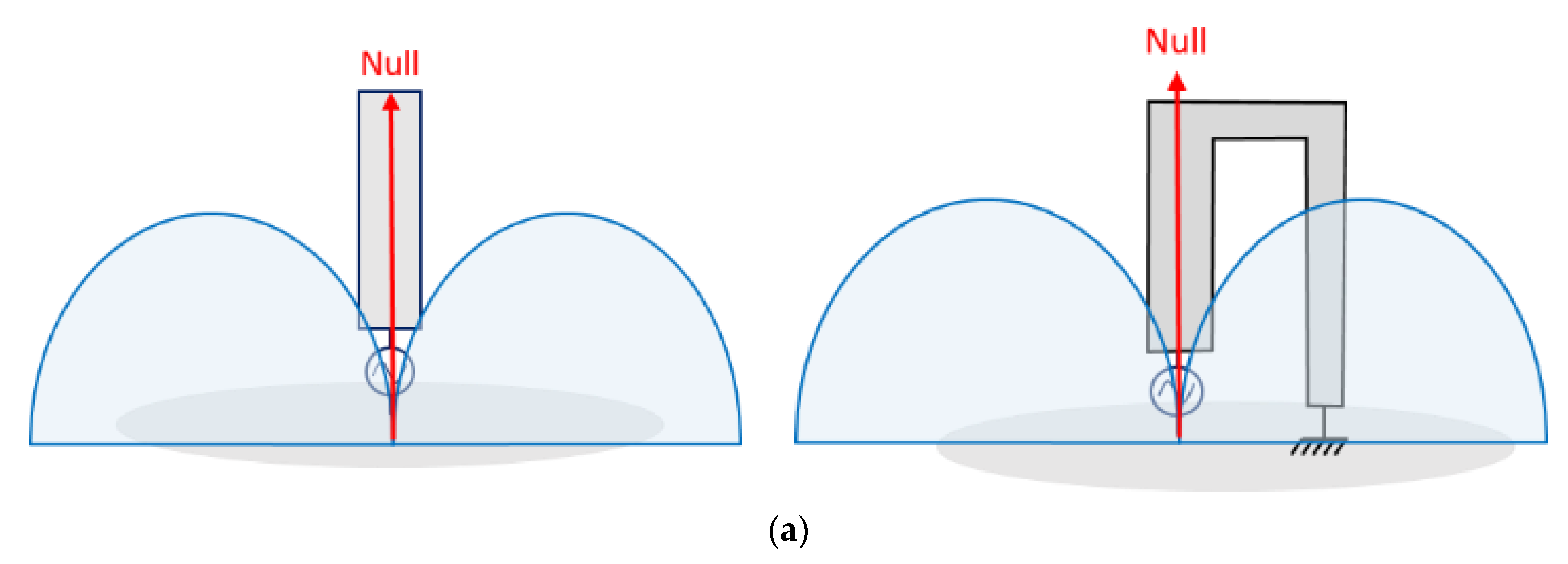
Figure 1. Thick monopole and folded monopole and their radiation pattern (a) at f = fr and folded monopole at f = 2 fr (b) and f = 5 fr (c).
Electronics 12 02788 g001aElectronics 12 02788 g001b
Figure 2. Representation of the classical folded dipole (a) and the folded dipole with vertical symmetry (b).
Electronics 12 02788 g002
Figure 3. Folded dipole with (a) asymmetrical and (b) symmetrical feeding and their respective radiation pattern.
Electronics 12 02788 g003
Figure 4. Folded dipole with (a) 0–90° feeding and (b) 90–0° feeding and their respective radiation pattern.
Electronics 12 02788 g004
Figure 5. Planar monopole (a) and dipole (b) structures. a1 and b1 represent the inner ellipse dimensions, a2 and b2 the outer ellipse.
Electronics 12 02788 g005
Figure 6. Simulations of radiation pattern at lower frequencies with different feed phase difference (at 1.6 GHz).
Electronics 12 02788 g006
Figure 7. Geometry of the folded dipole fed by microstrip line to slot line transition: (a) top view, (b) bottom view.
Electronics 12 02788 g007
Figure 8. Variation of reflection coefficient for different l1 lengths.
Electronics 12 02788 g008
Figure 9. Variation of reflection coefficient for different stub angles (θ).
Electronics 12 02788 g009
Figure 10. Prototype of the folded dipole antenna: (a) top view, (b) bottom view.
Electronics 12 02788 g010
Figure 11. Measured and simulated performances of the semi-elliptical dipole: (a) reflection coefficient, (b) radiation efficiency and (c) max gains.
Electronics 12 02788 g011
Figure 12. Simulated and measured radiation patterns in (a) phi = 0° plane and (b) phi = 90° plane.
Electronics 12 02788 g012
Figure 13. Photograph of the measured dipole antenna inside StarLab (MVG) anechoic chamber.
Electronics 12 02788 g013
Table 1. Optimized dimensions of the proposed antenna.
Parameters Value (mm)
a116
a220
b120
b280
g0.3
r12
l118.4
l28.85
l353
w14.1
w24.2
r5.42
θ180°
Table 2. Performances of the mentioned antennas and the semi-elliptical folded dipole antenna.
ReferenceTypeBandwidth (GHz)Gain (dBi)Reconfigurability
[9]Square monopole2.38–5.21.5–4.5No
[16]Folded dipole30.3–53.74.6–6.7No
[17]Modified folded dipole26.3–29.755.51No
[21]Thick Folded dipole1.2–4.078.2–11.5No
[22]Dipole26.5–38.24.5–5.8No
[23]Tapered slot antenna6.2–12.33–6No
[24]Vivaldi antenna2.9–14.25.5–9No
This workS11 < −6 dBFolded dipole2.3–262.9–8.2Yes
S11 < −10 dB3.3–8, 9.8–12.6 and 13.2–26
Disclaimer/Publisher’s Note: The statements, opinions and data contained in all publications are solely those of the individual author(s) and contributor(s) and not of MDPI and/or the editor(s). MDPI and/or the editor(s) disclaim responsibility for any injury to people or property resulting from any ideas, methods, instructions or products referred to in the content.