Article

An Autonomous Humanoid Robot Designed to Assist a Human with a Gesture Recognition System

Department of Mechatronic Devices, Poznan University of Technology, Piotrowo Street 3, 60-965 Poznan, Poland
*
Author to whom correspondence should be addressed.
Electronics 2023, 12(12), 2652; https://doi.org/10.3390/electronics12122652
Submission received: 14 April 2023 / Revised: 7 June 2023 / Accepted: 9 June 2023 / Published: 13 June 2023
(This article belongs to the Special Issue Autonomous Robots: Design, Sensing and Control)

Abstract

:
This paper presents the design of an autonomous humanoid robot designed to optimize and enrich customer service in showrooms, e.g., electronic equipment, mobile network operators, and generally in stores with various articles. The proposed humanoid robot design is distinguished by two key components: a sensor-equipped mobile platform with drives and a body featuring a head outfitted with a touch tablet and an RGBD camera. The control system enables autonomous navigation in both known and uncharted environments, with a special focus on diverse, crowded, and cluttered spaces. To enhance its adaptability, this robot is not only fitted with LIDAR sensors but also cliff and ultrasonic sensors. While the interactive ability with humans is an expected functionality, this paper brings forth certain distinct innovations in humanoid robot design for customer service. One of these unique aspects includes the robot’s ability to physically alter its configuration, such as rotating its head and adjusting the height of its torso to maintain line-of-sight with the customer. This capability signifies a novel degree of spatial responsiveness that exceeds static interaction. Moreover, the proposed robot is equipped with a user-friendly gesture recognition system, uniquely designed to detect and recognize simple human hand gestures. This attribute paves the way for understanding simple commands such as requests for assistance. Upon recognizing a request, the robot tailors its services by following the person around the showroom, effectively assisting and answering customer queries or displaying requisite information on its screen. This active assistance model, specifically tailored for human interaction, showcases the robot’s unique capability to respond proactively and dynamically to human inputs.

1. Introduction

In the swiftly advancing world of robotics, mobile robots have seen a surge in usage across diverse settings, tasked with various roles that largely involve interaction and cooperation with humans [1,2,3]. The focus of this paper is the development of an autonomous humanoid robot designed for these interactive tasks, with a special emphasis on customer service environments such as hotels, stores, and hospitals.
The authors of [2] discussed the utilization of robots in healthcare recently. They discovered that a considerable number of robots deployed in hospitals aim at facilitating direct cooperation with patients. The authors of [4] introduced a rudimentary robot equipped with a screen and camera, designed to function as a personal assistant and walk-helper. Subsequent work continued on this robot, with the authors delineating and demonstrating the holonomic system of the robot’s mobile base [5]. The authors of paper [6] also exhibited a remotely operated system for the provision of aid.
In [7], human-robot collaboration for on-site construction was discussed. A system designed to augment construction productivity and safety by synchronizing robot intelligence with human skills was showcased. It was pointed out that the rising popularity of personal robots introduces numerous challenges, one of which is security. Robots are often stronger and faster than humans, potentially creating hazardous situations. The second challenge, pertinent to this paper, is the communication gap between the robot and the human. Conventionally, a robot designed to assist a human will typically not cooperate with qualified individuals possessing advanced programming knowledge. Consequently, robot communication cannot rely on complex interfaces but must utilize interfaces comparable to natural human interactions. Robots designed to cooperate with humans should be capable of understanding speech or gestures for natural communication.
There is also a category of robots known as Attract, Interact, and Mindset (AIM). Their function is to draw attention to products in stores or shopping malls, then present offers and advertisements, or assist in shopping. Many AIM robots have been introduced in recent years [8,9,10,11,12], typically comprising a mobile base, a torso with a touchscreen, and a camera. The simplest models [8] offer touchscreen interactions, while more sophisticated ones incorporate voice recognition [9,10]. The tallest model [11] enhances visibility but may intimidate some users. A unique model [12] incorporates gesture recognition for natural interaction. However, none offer the comprehensive interaction modalities and height-adjustable design of our proposed autonomous humanoid robot.
Gesture recognition systems, which are increasingly leveraging artificial intelligence, have become popular recently. Their reliability has improved due to ongoing advancements in algorithms, programming frameworks, and large datasets necessary for such models. The application of gesture recognition systems has been widely discussed in publications [13,14,15,16].
Paper [13] describes a basic system for recognizing gestures, hands, and faces. The authors suggested wide-ranging applications of this system, such as facilitating communication for deaf individuals, enabling children to interact with computers or other devices, detecting lies, or monitoring patients in hospitals. The authors of paper [14] introduced hand gesture recognition systems using 3D depth sensors and reviewed widely-used commercial sensors and datasets. Various gesture recognition systems based on 3D hand modeling, static hand recognition, and hand trajectory tracking were also described. Similar insights into gesture recognition methods were provided in [15], while [16] presented various applications of gesture recognition systems in the realm of human-computer interaction.
Gesture recognition systems have also found an application in robotics. There are environments where a robot may struggle to recognize human speech, such as crowded or noisy places such as shopping malls or factories. Here, robots need alternative communication methods, such as gestures. Given the advancements in image analysis algorithms and portable hardware, robots equipped with various types of cameras could leverage human gesture recognition for interaction.
The authors of [17] suggested the use of a gesture recognition system for therapy with children diagnosed with Autism Spectrum Disorders, as these children often struggle with imitating gestures. They proposed therapeutic games involving joint gesture imitation by the robot and children. The authors of [18] designed a non-verbal communication system using gesture recognition for people fluent in sign language. In [19], a real-time gesture recognition system implemented in a dynamic human-robot application was presented. Paper [20] presented a system where the UR5e robot was operated via gestures in collaboration with humans. The authors of [21] proposed a comprehensive system for gesture-based teleoperation, tested in a pick-and-place case study. The application of a gesture recognition system was also reported in [22], where an agricultural robot with a ZED 2 camera was presented. Recent studies such as [23,24,25] have used the MediaPipe open-source framework [26] for real-time gesture recognition.
In contrast to the existing literature, our innovative mobile humanoid robot has been specifically designed to operate effectively in crowded and noisy environments. Equipped with a gesture recognition system, the robot can understand and respond to human gestures, thus facilitating non-verbal communication when voice recognition might be impractical. This is particularly useful in noisy places such as shopping malls or factories.
The proposed robot introduces several novelties to the challenges associated with traditional robot designs. A unique feature of our design is its ability to adjust its height by modifying the position of its torso, enhancing its interactive capabilities by adapting to the height of the human it is engaging with.
Moreover, our design incorporates an advanced gesture recognition system based on artificial intelligence, capable of accurately and swiftly following human commands. The system uses data from an RGBD camera mounted on the robot’s movable head. The head is equipped with microphones, speakers, a touchscreen and a camera, enabling efficient customer service without the need for continuous human intervention.
Finally, our design presents a cost-effective solution that could significantly reduce the expense of robotic assistants. Despite the increasing market presence of such devices, their high price is a barrier to their widespread adoption. By addressing this issue, we anticipate our affordable design could boost the popularity of robotic assistants.

2. Materials and Methods

2.1. Construction of the Robot

The designed robot consists of a mobile base that is equipped with drive wheels, caster wheels, a main control unit, and sensors. The next part of the robot is a movable torso on which a router and an NVIDIA Jetson TX2 are mounted, serving as a module for calculations related to computer vision and artificial intelligence (AI) models. The last element of the robot is a movable head, which is equipped with a touch tablet, RGBD camera, microphones and speakers. The components of the robot are shown in Figure 1.
The robot is equipped with a total of four drives. Two are located in the base and are used to move the robot around the environment. The robot uses a differential drive mode using two independently driven wheels located on both sides of the robot’s base. The maximum speed of the robot, resulting from its construction and the used motors, is 0.6 m/s, but it has been limited by software to 0.25 m/s for safety reasons. The base of the robot is 470 mm by 560 mm, which allows the robot to move in tight places but also ensures the stability of the entire mechanical structure of the robot. The next drive is located in the robot’s torso and is used to change its height so that it can adjust to, for example, the height of a human. While driving, the robot can reduce its height to achieve better stability. The height of the robot can vary from 1.40 m to 1.75 m; the range of motion of the robot’s torso is 0.35 m. The fourth and last drive is located in the robot’s head and is used to turn the robot’s head right and left. The range of head movement is ±45°. A summary of the basic parameters of the robot’s motion is presented in Table 1.

2.2. Autonomous Navigation

The Robot Operating System (ROS) middleware [27] was used to manage the work of the robot. ROS is an open-source platform for software development and robot control.
Various packages and programs (nodes) were launched on two computers of the robot, responsible, among others, for particular functionalities of the robot. They are listed and described below.
  • Communication and receiving data from sensors (e.g., LIDAR) and communication with low-level controllers (e.g., Roboclaw, dedicated low-level controller). Data from sensors such as IMU, ultrasonic sensors, optical sensors, and limit switches were collected by the dedicated low-level controller. The power controller published data on the batteries’ actual state, including the voltage and current usage.
  • Localization of the robot in the environment. The robot’s odometry was calculated from the IMU and encoders on its drive wheels. The Extended Kalman Filter (EKF) [28,29] was used to combine the odometry derived from the rotation of the wheels with data from the IMU in order to estimate the final odometry from two different sources.
  • Controlling the individual axes of the robot, i.e., controlling the drive wheels, torso, and head. A differential drive mode was used to control the drive wheels. A velocity command was used for controlling, and it was split and then sent to the two wheels of differential drive wheels.
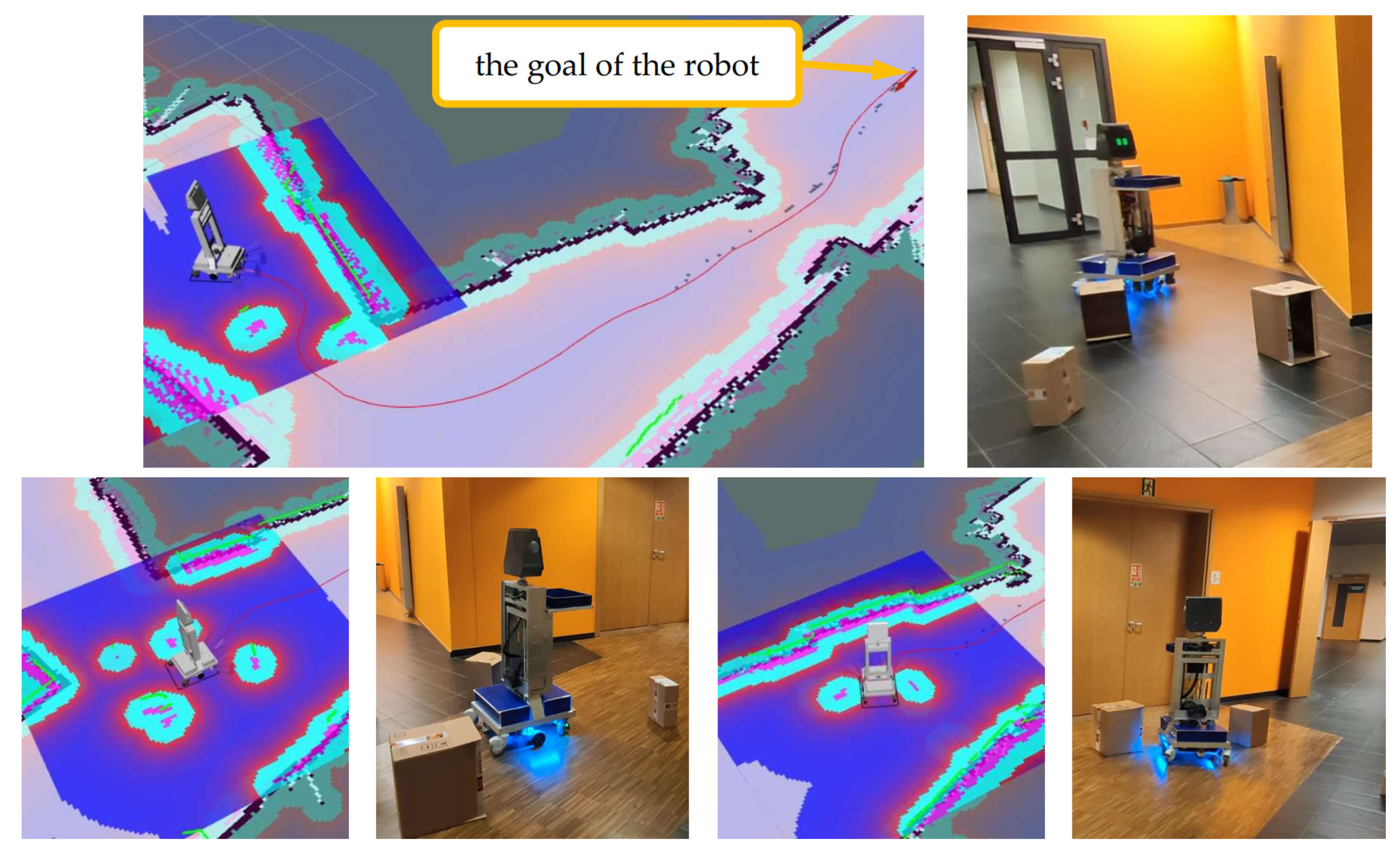
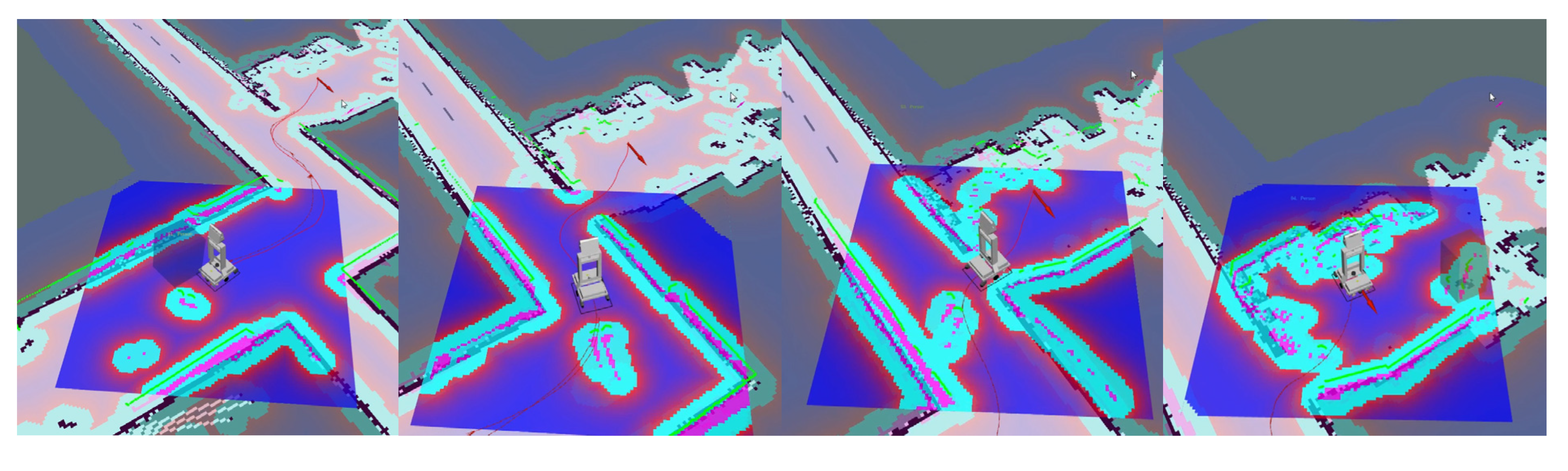
  • Autonomous robot movement. The module was used to detect obstacles and avoid them, and to determine the global and local path of the robot’s movement from its actual position on the map to the goal position. For this purpose, the move_base package, whose inputs included the kinematic parameters of the robot, data from the LIDAR and ultrasonic sensors, odometry, and the current map of the environment, was employed. This package’s output was the robot’s velocity, which was computed by the local planner, a submodule of the move_base package responsible for creating a local path for the robot in the robot’s proximity environment. The move_base package additionally generated a global path that connected the robot’s actual position and the goal position.
  • Robot model and kinematic structure description. The model took into account the masses and moments of inertia as well as the kinematic structure of the robot.
  • Mapping and localization in the created map. The SLAM-Gmapping algorithm was used for simultaneous creation and localization in the created map. The localization in the already produced map was carried out using the Adaptive Monte Carlo Localization (AMCL) algorithm.
  • Camera and artificial intelligence model packages. The robot was equipped with algorithms for face detection, gesture recognition, etc.
The ROS system includes RViz software, which served as a data visualizer that was published on specific topics. This software was able to visualize the robot model, the map currently created by the robot, data from sensors, the path of the robot’s movement, costmaps, and images from the camera, etc. An example of visualization of these data is shown in Figure 2.
In order to ensure autonomous driving of the robot, Simultaneous Localization and Mapping (SLAM) algorithms were implemented. These types of algorithms allow the creation of a map of the environment while locating yourself in the environment. The main sensor that is used in these types of algorithms is LIDAR. In addition, an odometry signal is necessary, which in the case of the presented robot was obtained using encoders mounted on the drive motors. Odometry was combined with the Inertial Measurement Unit (IMU) sensor data using the Extended Kalman Filter (EKF) [28,29]. In the ROS environment, the output of the SLAM algorithm was a map and the corrected position of the robot.
Various available SLAM algorithms were tested, such as CrsmSLAM [30], HectorSLAM [31], Cartographer [32,33], and Gmapping [34,35,36]. Each of the algorithms was launched and tested. The Gmapping algorithm was selected for further work and fine-tuned. To move around on the created map, the Adaptive Monte Carlo Localization (AMCL) algorithm was used. This algorithm is a variant of the Monte Carlo Localization (MCL) [37,38] algorithm, which is enhanced with an algorithm to adjust the number of particles based on the distance of KL [39].

3. Results

3.1. Robot Operation in a Cluttered Environment

During the research, the robot’s behavior in a crowded and dynamically changing environment was tested. The correct operation of the robot’s autonomous systems responsible for moving to a given point was tested. In the testing, the target point was determined randomly on the map by the test software. The task of the robot was to move from the current position to the preset position.
The initial tests consisted in placing obstacles in the form of cardboard boxes in the robot’s path, which were rearranged by the operator during the robot’s movement. Figure 3 shows time-lapse photos from the test. The odd-numbered photos show the RViz visualization environment. The even-numbered photos show the robot placement during the test. In the pictures, it can be seen that the robot control system recalculates the path of the robot’s movement (the red line between the robot’s actual position and goal position-red arrow) after each change in the distribution of obstacles.
The next stage was the testing of the robot’s autonomous systems in an environment where there were a lot of people who were moving around. Such an environment changes very dynamically and the robot must react quickly to changes that occur in such an environment.
Figure 4 shows time-lapse photos from the test. The robot has been marked in the figure in a red frame. The odd-numbered photos show robot placement during the test. The even-numbered photos show the RViz visualization environment. In the photos from the visualization environment, it can be seen how the robot with the LIDAR sensor (green dots) detects people; the robot only detects human legs.
In the tested environment, there were many obstacles between the current position of the robot and its goal position. During the tests, there were situations in which the robot could not find the optimal path to avoid all obstacles without collision (there were too many people around the robot). In such a situation, the robot stopped and waited for the environment to change. If it changed in such a way that the robot could continue to the destination without collision, the robot began moving again. During the tests, it was proved that our robot could safely and autonomously operate in a crowded environment.

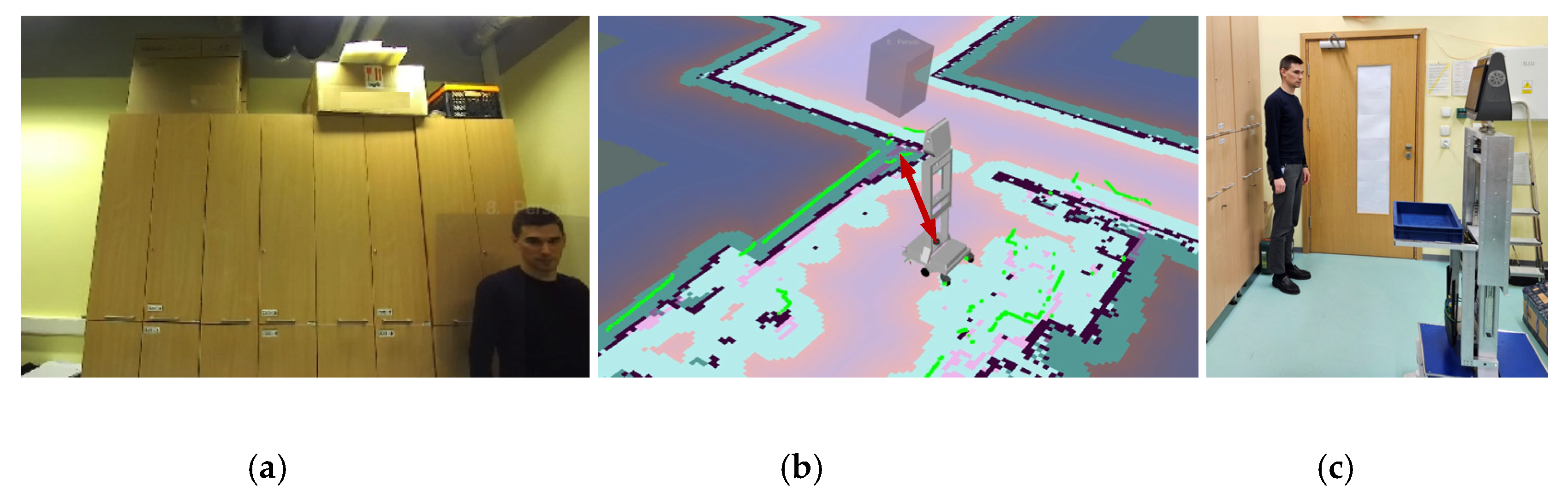
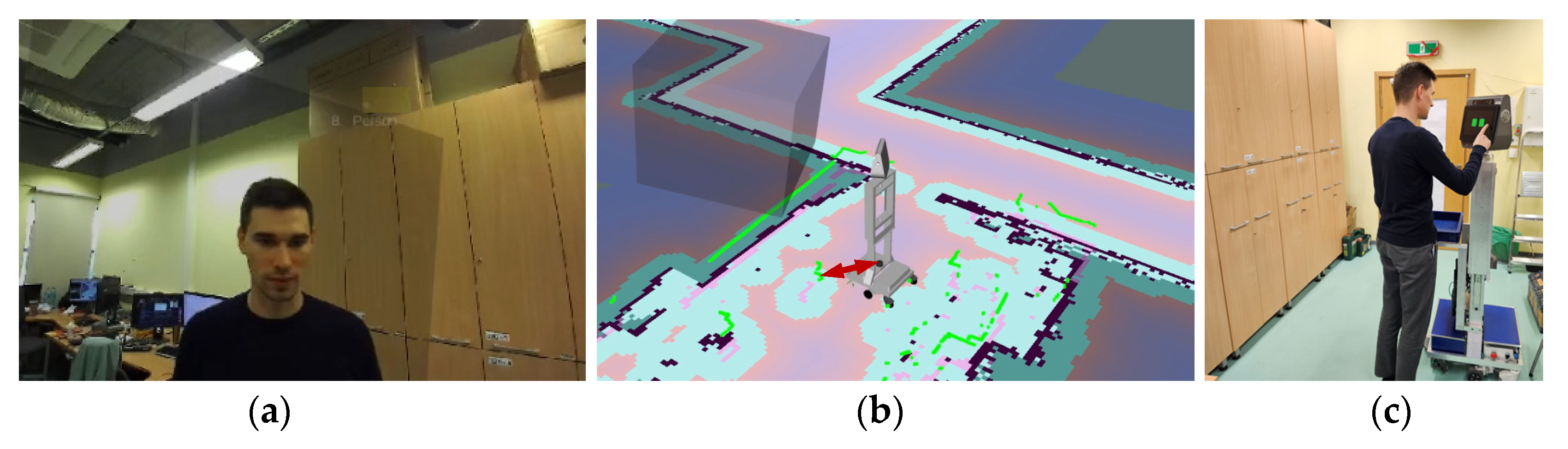
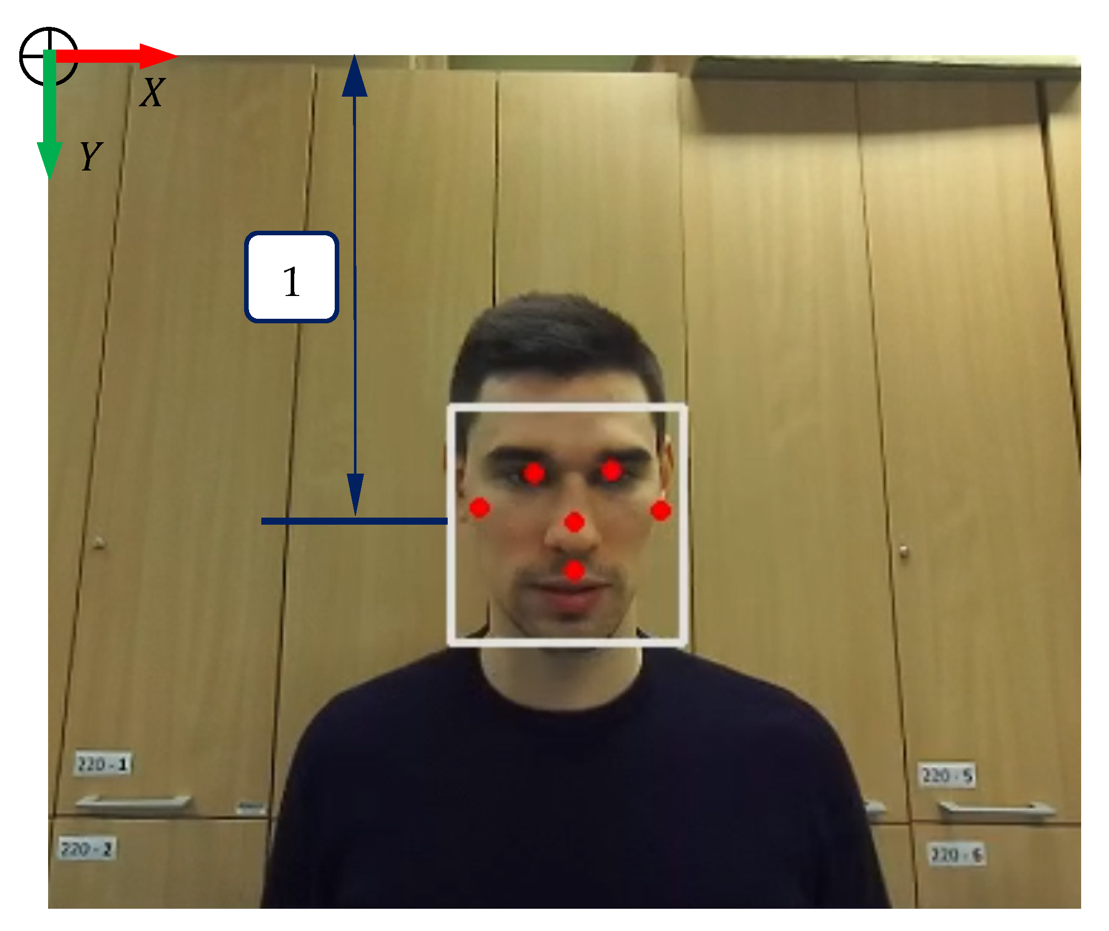
3.2. Human Tracking with Robotic Head Rotation

In order to implement the functionality of tracking the human by rotating the head of the robot, first the software for human detection and determining the distance between the camera and the human was implemented. A detected human was marked on the map created by the robot. This means that the position of the human was known relative to the origin of the map coordinate system and relative to the camera coordinate system. The ZED 2 camera is equipped with the functionality of detecting a person and tracking their position relative to the camera. Using neural networks, functionality was implemented to detect objects present in both the left and right camera images. Then, the 3D position of each object (human), as well as its bounding box, was calculated using data from the depth modulus. These also allowed objects to be tracked in the environment over time, even if the camera was moving.
After determining the position of the human in relation to the position of the camera on the map located in the head, the position of the human in relation to the robot’s base (which was fixed in relation to the rotating head) was calculated. The reference frame of the human position relative to the robot and head with the camera is shown in Figure 5. The figure shows the robot in a world (map) coordinate system ( x W ,   y W ). The robot’s coordinate system ( x R ,   y R ) was marked in blue and the camera coordinate system ( x c ,   y c ) was marked in green. The camera recognized the human body and gave the position relative to the camera frame ( x c p o s ,   y c p o s ). The person was marked in the form of coordinates ( x h p o s ,   y h p o s ) for the X and Y axes in relation to the robot’s position. By changing the coordinate system of the detected human from the camera to the robot’s base, it was possible to calculate the angle between the person and the robot’s base according to the formula:
α = atan ( y h p o s x h p o s )
The rotating angle of the head was sent to the head controller.
The head of the robot followed the detected human only if a human was in proximity distance to the base of the robot. The distance threshold was set to 0.5 m. If this distance was greater, even though the human was detected by the robot, the head did not follow them. If the human was at a distance of less than 0.5 m, the robot’s head followed the changing position of the human.
The two figures below show both the situation in which the robot’s head followed a human being in close proximity to the robot, and the situation in which the human, although detected, was too far from the robot and the robot’s head did not follow the human’s position. Each of the two figures (Figure 6 and Figure 7) consists of three planes, the first of which (a) is an image from the camera placed on the robot’s head. The middle image (b) is a visualization of the robot and the surrounding environment, including the human detected in the RViz. The human is marked as a cuboid. The red arrow shows the distance between the detected human and the robot. The last plane (c) is a photo showing the placement of the robot and human in the test environment.
Figure 6 shows a situation where a human was detected by a robot but was too far away for the robot’s head to follow. In Figure 6b,c it can be seen that the robot’s head is in the center position. When a human approached the robot, the angle of rotation of the robot’s head depended on the current position of the human. Figure 7 shows situations when a human was in close proximity to the robot, standing to its left. In planes (Figure 7b,c) it can be seen that the robot’s head turns towards the changing position of the human.
Due to the fact that the robot rotates its head and adjusts it to the human’s position, it is easier for the human to interact with the robot. A human can freely move around the robot while watching the content shown by the robot on the screen; in addition, if the human is required to enter specific data on the touch panel, the human can do it without changing position and standing in front of the robot. In addition, this behavior of the robot humanizes it a bit, because during interaction it is similar to a real human.

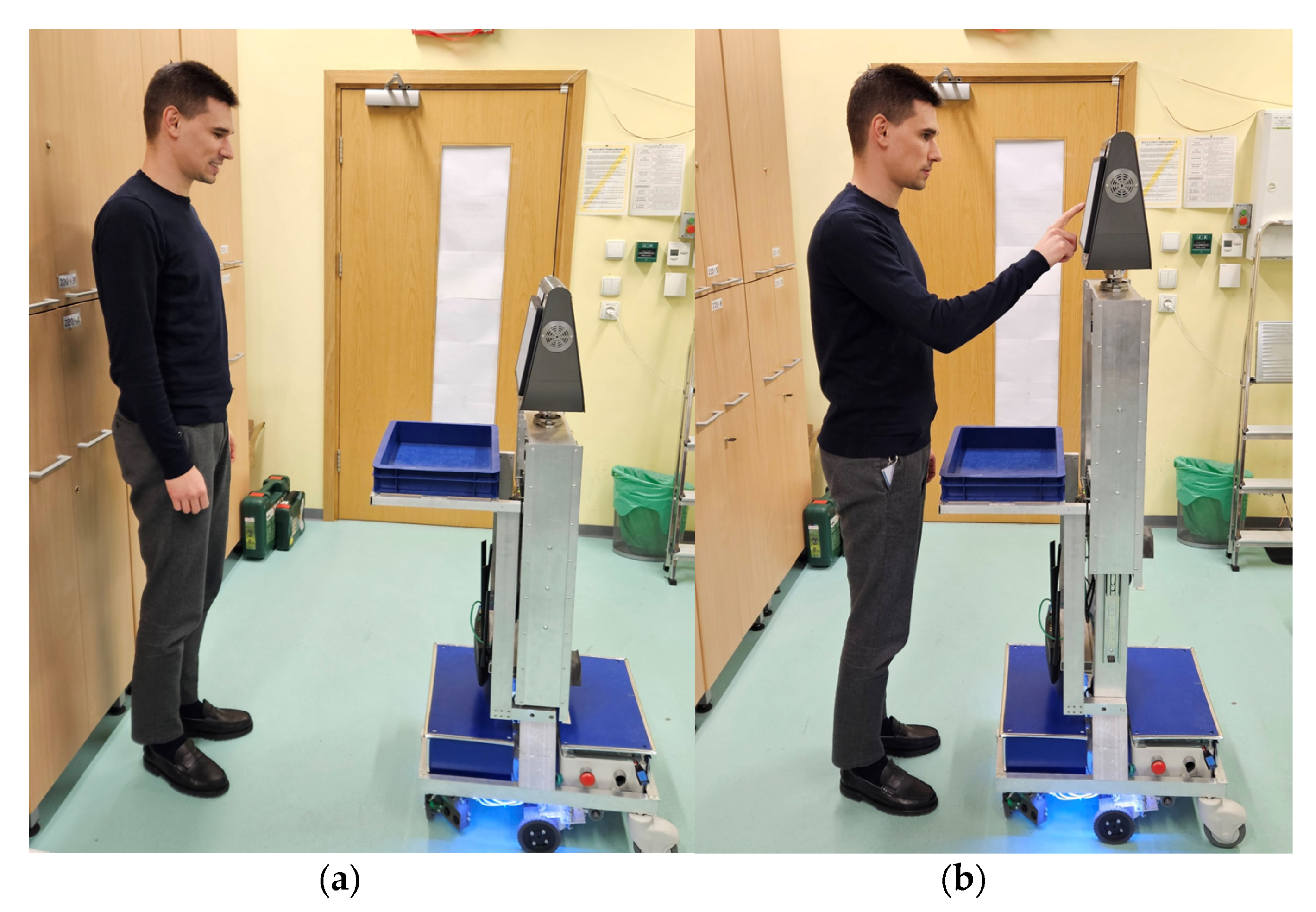
3.3. Adjusting the Height of the Torso According to Human Height

An additional module facilitating human interaction with the robot is adjusting the robot’s height to the human’s height by moving the robot’s torso. Hence, a person can comfortably view content and enter data using the touch panel without the need to bend down or stand on tiptoes. Adjusting the height of the robot is based on detecting the face of a human being in close proximity to the robot. The face is detected in the image from the camera in the robot’s head.
In the first stage, the face is detected and marked as a bounding box, hence the coordinates of the face in the camera image are known. Then, the center of the bounding box for the Y -axis is centered in certain proportions in the Y -axis of the image as shown in Figure 8. The robot’s height control algorithm tries to keep the human face at 65% of the image height ( Y -axis). The current position of the bounding-box face in Figure 8 is marked with (1). If the camera image is 1280 × 720 pixels, the bounding-box position of the face for the image is 720∙0.65 = 468 pixels. A PID controller is used as the height controller of the robot, depending on the position of the human face in the image. Its target position is the y position of the bounding box face at 65% of the image height ( Y -axis), the input is the y position of the face in the image, and the output is the change of the torso height.
Figure 9 shows time-lapse photos of the image from the camera mounted in the robot’s head as the robot adjusted its height to the human. It can be seen how the human’s face in the first photo is in the upper part of the frame, and in the last one it is in the lower part of the frame. Figure 10 shows the initial and final height of the robot after adjusting it to human height.

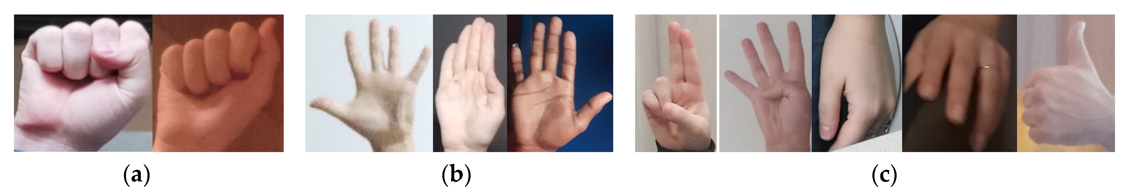
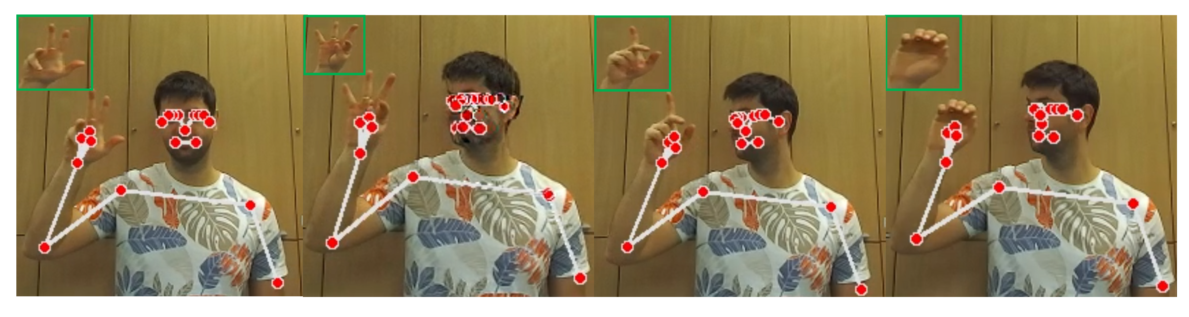
3.4. Gesture Recognition System for Issuing Commands to the Robot

In order to improve the interaction between the robot and the human and to issue commands to the robot, a dedicated system was designed for recognizing gestures by the robot, which were then assigned to specific commands.
The gesture detection module consisted of algorithms based on artificial intelligence and convolutional neural networks (CNN). A dedicated dataset consisting of about 78,000 photos of hands was created to train the algorithm. The set was developed on the basis of the HaGRID dataset [40]. The original HaGRID dataset contains person images in different scenes and lighting conditions. Our dataset contained only images of hands with different gestures that were cropped from the full image. The dataset created by us was divided into three classes, to which commands for the robot were assigned thus:
  • fist—hand clenched into a fist; command: follow human, human requires robot assistance;
  • palm—open hand; command: go back to the starting place, the human no longer needs the robot’s assistance,
  • unknown—unknown gesture, any other hand shape; command: execute the last command.
Figure 11 shows sample photos from the created dataset. The hands in the dataset consist of hand images that are lit differently and were taken against different backgrounds, for the left and right hands, and in different poses. All this was aimed at ensuring the best classification accuracy for the model implemented in real conditions on the robot. Classification accuracy was the main criterion for evaluating the model, and was calculated using the equation:
a c c u r a c y = c o r r e c t   p r e d i c t i o n s t o t a l   p r e d i c t i o n s · 100
Accuracy is expressed in percent. Correct predictions are a sum of true positive and true negative examples.
During the tests of the gesture recognition system, various CNN architectures were tested, including ResNet152, Resnet50, ResNet101 [41], InceptionResNet [42], Inception [43], and EfficientNet [44]. Finally, the ResNet152 architecture was chosen, because it achieved the highest classification accuracy, i.e., about 96.1% for the validation set. However, for all tested models the achieved accuracy for the validation set was above 92%. Table 2 presents the obtained accuracies for the validation set for individual models. The input to each model was a picture of a hand with pixel dimensions (85, 85, 3). Each model was trained for 20 epochs on the dataset described above. For optimization parameters of the tested models, an Adam [45] optimizer was used with a learning rate equal to 1e-4. As a loss function, a categorical cross-entropy loss function was used, which is given by the following formula:
L = i k y i log ( y ^ i )  
where:
k —is the number of classes,
y —is the ground truth label for a given class,
y ^ —is the probability for a given class.
Figure 12 shows the waveforms presenting the classification accuracy for the training and validation sets during learning for each tested model. The accuracy presented in Figure 12 was in the range between 0 and 1 (0–100%).
Figure 13 shows confusion matrices for the validation set consisting of about 3500 images. These matrices show multiclass classification problems by comparing the predicted labels from a model and ground true values from the dataset. As can be seen, all models had the biggest problem with correctly classifying the images of the fist. Models sometimes classified these images as unknown. However, this was a very small percentage as all models achieved very high accuracy. Out of approximately 3500 tested images, an average of 100 fist images for each model were classified as unknown. For the proposed solution, it does not matter much, because the unknown class does not issue any command to the robot. The percentage of incorrectly classified fists and palms as unknown was very small, which was important from the point of view of the proposed solution because any incorrectly detected fist or palm can issue a wrong command to the robot.
The Resnet152 neural network consists of 152 layers, including convolutional layers that form the residual blocks, which are shown in Figure 14.
Residual building blocks are defined as:
z = F ( x { W } ) + x
where W is a parameters matrix from the weight layer, and x is the input to the residual block. The function F ( x ) represents the residual mapping that the model is learning. The main idea behind the residual block is the identity (skip) connection between the layers. It helps very deep networks to learn complicated patterns in data and improves gradient backpropagation.
The last layers in ResNet152 model were fully connected layers; between these layers and the convolutional layers, the global average pooling layer was used. The model, despite having so many layers, consists of only about 58 million parameters. The network was trained for about 1 h for 20 epochs and for the described dataset on a computer with two NVIDIA RTX 2080Ti GPUs. A distributed training method was used, which allowed one model to be trained on two separate graphics cards. For comparison, the training time of the model trained with only the AMD Ryzen Threadripper 2950X CPU (16 cores, 32 threads) was over 19 h.
ResNet152, input to which was only the image of the hand itself, was one of the elements of the entire module for recognizing gestures based on the image from the camera placed in the robot’s head. The diagram of the entire gesture recognition module is shown in Figure 15. Data from individual submodules were taken into account when determining the final command for the robot. The entire gesture recognition module consisted of three sub-modules:
  • pose detection submodule,
  • hand detection submodule,
  • ResNet152.
The detection of the human pose and the hand was developed on the basis of the Single Shot MultiBox Detector (SSD) architecture [46]. The gesture recognition module was implemented in TensorFlow framework and Python language.
The input to the first submodule is an image from a camera placed in the robot’s head of size (1280, 720, 3). The output from the pose detection submodule is the position of individual landmarks on the human body. The submodule returns 32 points (coordinates), e.g., nose, hand, shoulder, knee, etc. The module for issuing commands to the robot is activated only when the hand of the detected person is raised above the right shoulder. In Figure 15a), the image from the camera has been marked with the number (1) for the position of the right shoulder, and the number (2) for the position of the hand. When the hand is raised above the right shoulder, the y position coordinate of the hand is less than the y position coordinate.
Due to the fact that the dataset contains photos of hands that were cropped in an almost perfect way (they did not contain unnecessary background), it was not possible to crop a rectangle of a fixed size, e.g., (80, 75, 3), which contained a hand based on the position of the hand. Such an image, which was the input of the ResNet152 network, was incorrectly classified in most cases, and the classification module should work with high reliability. To tackle this problem, the hand detection submodule was applied. Its input was an image of size (140, 170, 3) created from the position of the hand in the camera image. If the input of the hand detection submodule was a camera image of size (1280, 720, 3), then the submodule did not give satisfactory results and did not detect hands reliably. The output from the hand detection submodule was landmarks for individual elements of the hand and a bounding box, which did not contain unnecessary background. Such a picture most closely resembled the pictures that were in the dataset used to train the ResNet152 network. The image that was the output from the hand detection submodule had a variable size, so it was resized to (85, 85, 3) dimensions so that it could match the desired input shape of the ResNet152 network. The output from the ResNet152 network was a vector of probabilities based on which of the three classes, fist, palm, or unknown, the image was assigned to.
As mentioned above, the module for issuing commands to the robot was active only if the hand of the detected person was raised above their right shoulder. Gesture, position, and hand recognition were still active, but no command was sent to the robot. Figure 16 shows a situation where a man’s hand is below his right shoulder.
In order to ensure the stability of the commands issued to the robot and to avoid a situation where the gesture recognition module detected a gesture for following a human in the first frame of the image, and in the second frame image detected a gesture for returning the robot to the starting point, an algorithm based on a moving average was proposed, analyzing the detected gestures from the last 15 frames of the image. The fist gesture—follow a person—was assigned a value of 1, and the palm gesture—return to the starting place—was assigned a value of 0. If the average of the last 15 frames was greater than 0.5, the command to follow a person was issued, if the average was lower, the command to return to the starting place was issued. This approach prevents unnecessary oscillations and issuing of unwanted commands to the robot. The ResNet152 network assigns a hand image to one of three classes, the first two being commands and the last being any other gesture. Examples of gestures labeled unknown are shown in Figure 17. The green frame on the left of each image shows the input image to the ResNet152 network.
Recognition of commands by the gesture recognition system we proposed, implemented in the autonomous robot, worked very reliably and accurately. During tests in various conditions, the gesture recognition system never recognized a gesture incorrectly, which did not result in issuing any incorrect commands to the robot. The stability of issuing commands to the robot was ensured by the analysis of several consecutive image frames and the highly-accurately-trained ResNet152 network.

3.5. Issuing Commands to the Robot by the Human

In the developed system, the robot can be given two commands to improve the interaction between the robot and the human. If the operator would like to move around the room and requires assistance from the robot to view content on a tablet or enter data on the screen, they should command the robot to follow them by raising their hand above the right shoulder and clenching it into a fist as shown in Figure 18.
Figure 19 shows the individual steps during the movement in the form of time-lapse photos. The odd-numbered photos show the image from the camera placed in the robot’s head with particular layers: map created by the robot, costmaps, data from sensors, the robot’s path, and its goal of movement. The even-numbered photos show the model of the robot and its surrounding environment. The current goal of the robot’s movement in individual photos has been marked with a red arrow, while the planned path of the robot’s movement to the goal position has been marked with a red line.
The last two photos in Figure 19 show a situation where the human has stopped and the robot has also stopped in front of him, waiting for his next move. In this case, the robot performs other activities, e.g., adjusting the height of the torso and following the position of the human rotating its head. If the human changes their position on the map, the robot starts following the human again. Figure 20 shows a situation in which the robot, standing in front of a human, was commanded to return to its starting position. The human raised his open hand above his shoulder, suggesting that the person no longer required the robot’s assistance. Figure 20a shows an image from a camera placed in the robot’s head with layers from the visualization environment; a human is marked as a blue cuboid. Figure 20b shows the visualization of the robot in the RViz environment; a human is marked as a blue cuboid in front of the robot.
Figure 21 shows time-lapse photos showing the robot’s path to the starting point after the human has issued a command suggesting that they no longer need the robot’s assistance. The first picture on the left (Figure 21) shows the first stage of the movement. The goal and the path of movement to the starting point have already been determined by the robot. In addition, in this photo, a person can be seen, marked in the form of a cuboid, still standing in front of the robot and giving commands. In the next three photos, it can be seen that the robot autonomously moves to the starting point and waits for further instructions.

4. Discussion

The work described in this article demonstrates significant strides in the design and construction of a mobile humanoid robot with enhanced user-interaction capabilities. This robot, incorporating advanced autonomous navigation, dynamic physical parameters, and a high degree of human interactivity, represents a solution for human-robot collaboration in a variety of settings.
The incorporation of SLAM and AMCL algorithms ensures reliable navigation by the robot, as they allow the robot to move in both known and unknown environments while taking into account and safely avoiding obstacles on the way to its destination. The effectiveness of these algorithms not only establishes a foundation for the robot’s core functionalities but also contributes to enhancing the user’s trust in the robot’s autonomy. The decision to make the robot’s torso and head movable is a notable improvement in the design of interactive robots. This allows the robot to adjust its height and direction of gaze to match the user’s, which results in a more human-like interaction. The ability to maintain eye contact and respond in a manner similar to human reactions makes the robot more approachable and increases the user’s comfort during the interaction. The successful implementation of a human detection and tracking module, along with the gesture recognition module, adds another layer of interactivity. These modules allow the robot to recognize humans and respond to hand gestures. The robot’s ability to mark a human’s exact location on the map also creates opportunities for further interaction and navigation capabilities. The decision to utilize various neural network architectures for the gesture recognition module ensured high accuracy in gesture recognition. The implemented solution, composed of three submodules, allowed the robot to adjust its height and rotate its head according to the human’s actual position, adding to the robot’s responsiveness and adaptability.
While this work has resulted in a promising solution for robotic human assistance, it also opens the door to potential future advancements. The prospects of developing and testing the robot in customer service scenarios, as well as analyzing the user experience, are exciting opportunities for further exploration. By evaluating user interactions with the robot, it may be possible to fine-tune its capabilities and improve the overall human-robot interaction experience.
The presented work has demonstrated results in the design and operation of a humanoid robot capable of interacting with humans and navigating its environment autonomously. However, it has its limitations and sets directions for future research and development. One limitation of the current system is its scalability. The deployment of a fleet of such robots and their coordinated operation will require advancements in multi-robot systems. Future work should therefore focus on developing algorithms and systems that can allow the robot to operate with other robots in larger, more complex environments and coordinate effectively. While the robot is equipped with algorithms for face detection and gesture recognition, its adaptability to diverse, dynamic environments could be improved. This includes its ability to interact with people of different ages, abilities, and cultural backgrounds, and to handle unexpected situations. Future research should consider incorporating more advanced AI algorithms and more robust sensor technology to enhance the robot’s adaptability.
On the other hand, deploying humanoid robots in public spaces raises a number of ethical and social concerns, particularly in terms of privacy, security, and human-robot interaction. Robots equipped with cameras and sensors could potentially capture and store data on individuals without their consent, breaching their privacy rights. They could also capture sensitive information in the environment that individuals might not want to share. Humanoid robots could potentially be hacked, leading to misuse of data or the robot itself. This could result in damage to property or even harm to individuals. As robots become more common in public spaces, they will inevitably interact more frequently with humans. This raises questions about how these interactions should be managed to ensure they are safe and positive. In our tests in a crowded environment, we noticed that people willingly interacted with the robot. People’s behavior towards the robot was positive and friendly. The authors did not notice a negative reception of the presented robot.
Public perception will play a critical role in the adoption and integration of humanoid robots in society. Therefore, transparency in design, deployment, and operation, and the inclusion of public opinion in regulatory decisions, will be vital for the successful and ethical application of such technologies.
Our autonomous humanoid robot excels in environments where traditional robots, such as those discussed in [2,4] might falter. While the robots described in these studies are used primarily in health care settings or as personal assistant robots, ours is designed for noisy and crowded environments such as shopping malls or factories, broadening the potential scope of application significantly.
The adaptability of our robot sets it apart from many discussed in the literature. The Attract, Interact, and Mindset (AIM) robots described in [8,9,10,11,12], while effective at attracting customer attention, lack the height-adjustability feature found in our robot. This adaptability improves the engagement experience as the robot can adjust its torso height to match the height of the human it interacts with. This detail, though seemingly minor, enhances the human-robot interaction experience.
The gesture recognition system of our robot is also noteworthy in comparison with those highlighted in [13,14,15,16]. While many systems rely on a mix of 3D hand modeling, static hand recognition, or trajectory tracking of the hand, our robot uses a comprehensive AI-based gesture recognition system. It leverages data from an RGBD camera on the robot’s head to follow human commands accurately, making it more robust and dynamic.
Moreover, compared to the therapy robots for children with Autism Spectrum Disorders presented in [17] or those for sign language communication in [18], our robot serves a wider audience. While the aforementioned robots cater to niche segments, ours is designed for general public use, further widening its reach and potential impact.
Finally, a key comparison point lies in the affordability of our robot. The cost of many robotic assistants, such as those found in [8,9,10,11,12], often proves to be a significant barrier to widespread adoption. Our design prioritizes cost-effectiveness, potentially leading to more widespread use and acceptance of such technology.
In summary, our proposed robot builds upon the strengths of existing technologies while addressing some of their limitations, making it a promising advancement in the field of humanoid robotics.

5. Conclusions

This paper presents a mobile humanoid robot, designed to assist in public spaces by following human operators via hand gestures. We have devised and tested a navigation system enabling it to operate in known and unknown environments while avoiding obstacles. Unique to this robot are its features for enhanced human interaction, including a height-adjustable torso and a rotating head that limits excessive movement and offers a more natural, efficient tracking of humans. Its human detection, tracking, and gesture recognition modules are based on several neural network architectures and offer precise location and interaction capabilities. In tests, the robot adeptly recognized and responded to human gestures.
In conclusion, this work presents a compelling contribution to the field of mobile humanoid robotics, showing that robots can successfully interact with humans in a natural, intuitive manner. This achievement has the potential to revolutionize the way we utilize robots in environments such as hotels, hospitals, and shopping malls, thus significantly enhancing the quality of services provided in these settings.

Author Contributions

Conceptualization, T.L. and D.W.; methodology, T.L.; software, T.L.; validation, T.L., D.W. and A.M.; formal analysis, T.L. and D.W.; investigation, T.L. and D.W.; resources, T.L. and D.W.; data curation, T.L. and D.W.; writing—original draft preparation, T.L. and D.W.; writing—review and editing, T.L., D.W. and A.M.; visualization, T.L.; supervision, A.M.; project administration, A.M.; funding acquisition, A.M. All authors have read and agreed to the published version of the manuscript.

Funding

This research was funded by the Polish Ministry of Science and Higher Education: 0614/SBAD/1565 and by the European Regional Development Fund: RPMA.01.02.00-14-B521/18.

Data Availability Statement

Not applicable.

Conflicts of Interest

The authors declare no conflict of interest.

References

  1. Ye, H.; Sun, S.; Law, R. A Review of Robotic Applications in Hospitality and Tourism Research. Sustainability 2022, 14, 10827. [Google Scholar] [CrossRef]
  2. Holland, J.; Kingston, L.; McCarthy, C.; Armstrong, E.; O’Dwyer, P.; Merz, F.; McConnell, M. Service Robots in the Healthcare Sector. Robotics 2021, 10, 47. [Google Scholar] [CrossRef]
  3. Vasco, V.; Antunes, A.; Tikhanoff, V.; Pattacini, U.; Natale, L.; Gower, V.; Maggiali, M. HR1 Robot: An Assistant for Healthcare Applications. Front. Robot. AI 2022, 9, 813843. [Google Scholar] [CrossRef] [PubMed]
  4. Palacín, J.; Clotet, E.; Martínez, D.; Martínez, D.; Moreno, J. Extending the Application of an Assistant Personal Robot as a Walk-Helper Tool. Robotics 2019, 8, 27. [Google Scholar] [CrossRef] [Green Version]
  5. Moreno, J.; Clotet, E.; Lupiañez, R.; Tresanchez, M.; Martínez, D.; Pallejà, T.; Casanovas, J.; Palacín, J. Design, Implementation and Validation of the Three-Wheel Holonomic Motion System of the Assistant Personal Robot (APR). Sensors 2016, 16, 1658. [Google Scholar] [CrossRef] [PubMed] [Green Version]
  6. Clotet, E.; Martínez, D.; Moreno, J.; Tresanchez, M.; Palacín, J. Assistant Personal Robot (APR): Conception and Application of a Tele-Operated Assisted Living Robot. Sensors 2016, 16, 610. [Google Scholar] [CrossRef] [PubMed] [Green Version]
  7. Zhang, M.; Xu, R.; Wu, H.; Pan, J.; Luo, X. Human–Robot Collaboration for on-Site Construction. Autom. Constr. 2023, 150, 104812. [Google Scholar] [CrossRef]
  8. Smart Delivery Robot-Pudu Robotics. Available online: https://www.pudurobotics.com/ (accessed on 2 April 2023).
  9. Cheetah Mobile—Make the World Smarter. Available online: https://www.cmcm.com/en/ (accessed on 2 April 2023).
  10. Schulenburg, E.; Elkmann, N.; Fritzsche, M.; Girstl, A.; Stiene, S.; Teutsch, C. LiSA: A Robot Assistant for Life Sciences. In Proceedings of the KI 2007: Advances in Artificial Intelligence, Osnabrück, Germany, 10–13 September 2007; Hertzberg, J., Beetz, M., Englert, R., Eds.; Springer: Berlin/Heidelberg, Germany, 2007; pp. 502–505. [Google Scholar]
  11. ARI—The Social and Collaborative Robot. Available online: https://pal-robotics.com/robots/ari/ (accessed on 2 April 2023).
  12. Intelligent Telepresence Healthcare Robot—SIFROBOT-1. Available online: https://sifsof.com/product/intelligent-telepresence-robot-sifrobot-1-1 (accessed on 2 April 2023).
  13. Mitra, S.; Acharya, T. Gesture Recognition: A Survey. IEEE Trans. Syst. Man Cybern. Part C Appl. Rev. 2007, 37, 311–324. [Google Scholar] [CrossRef]
  14. Cheng, H.; Yang, L.; Liu, Z. Survey on 3D Hand Gesture Recognition. IEEE Trans. Circuits Syst. Video Technol. 2016, 26, 1659–1673. [Google Scholar] [CrossRef]
  15. Suarez, J.; Murphy, R.R. Hand Gesture Recognition with Depth Images: A Review. In Proceedings of the 2012 IEEE RO-MAN: The 21st IEEE International Symposium on Robot and Human Interactive Communication, Paris, France, 9–13 September 2012; pp. 411–417. [Google Scholar]
  16. Rautaray, S.S.; Agrawal, A. Vision Based Hand Gesture Recognition for Human Computer Interaction: A Survey. Artif. Intell. Rev. 2015, 43, 1–54. [Google Scholar] [CrossRef]
  17. Ivani, A.S.; Giubergia, A.; Santos, L.; Geminiani, A.; Annunziata, S.; Caglio, A.; Olivieri, I.; Pedrocchi, A. A Gesture Recognition Algorithm in a Robot Therapy for ASD Children. Biomed. Signal Process. Control 2022, 74, 103512. [Google Scholar] [CrossRef]
  18. Illuri, B.; Sadu, V.B.; Sathish, E.; Valavala, M.; Roy, T.L.D.; Srilakshmi, G. A Humanoid Robot for Hand-Sign Recognition in Human-Robot Interaction (HRI). In Proceedings of the 2022 Second International Conference on Advances in Electrical, Computing, Communication and Sustainable Technologies (ICAECT), Bhilai, India, 21–22 April 2022; pp. 1–5. [Google Scholar]
  19. Scoccia, C.; Menchi, G.; Ciccarelli, M.; Forlini, M.; Papetti, A. Adaptive Real-Time Gesture Recognition in a Dynamic Scenario for Human-Robot Collaborative Applications. Mech. Mach. Sci. 2022, 122 MMS, 637–644. [Google Scholar] [CrossRef]
  20. Mustafin, M.; Chebotareva, E.; Li, H.; Martínez-García, E.A.; Magid, E. Features of Interaction Between a Human and a Gestures-Controlled Collaborative Robot in an Assembly Task: Pilot Experiments. In Proceedings of the International Conference on Artificial Life and Robotics (ICAROB2023), Oita, Japan; 2023; pp. 158–162. [Google Scholar]
  21. Zhang, W.; Cheng, H.; Zhao, L.; Hao, L.; Tao, M.; Xiang, C. A Gesture-Based Teleoperation System for Compliant Robot Motion. Appl. Sci. 2019, 9, 5290. [Google Scholar] [CrossRef] [Green Version]
  22. Moysiadis, V.; Katikaridis, D.; Benos, L.; Busato, P.; Anagnostis, A.; Kateris, D.; Pearson, S.; Bochtis, D. An Integrated Real-Time Hand Gesture Recognition Framework for Human–Robot Interaction in Agriculture. Appl. Sci. 2022, 12, 8160. [Google Scholar] [CrossRef]
  23. Damindarov, R.; Fam, C.A.; Boby, R.A.; Fahim, M.; Klimchik, A.; Matsumaru, T. A Depth Camera-Based System to Enable Touch-Less Interaction Using Hand Gestures. In Proceedings of the 2021 International Conference “Nonlinearity, Information and Robotics” (NIR), Innopolis, Russia, 26–29 August 2021; pp. 1–7. [Google Scholar]
  24. Veluri, R.K.; Sree, S.R.; Vanathi, A.; Aparna, G.; Vaidya, S.P. Hand Gesture Mapping Using MediaPipe Algorithm. In Proceedings of the Third International Conference on Communication, Computing and Electronics Systems, Coimbatore, India, 28–29 October 2021; Bindhu, V., Tavares, J.M.R.S., Du, K.-L., Eds.; Springer: Singapore, 2022; pp. 597–614. [Google Scholar]
  25. Boruah, B.J.; Talukdar, A.K.; Sarma, K.K. Development of a Learning-Aid Tool Using Hand Gesture Based Human Computer Interaction System. In Proceedings of the 2021 Advanced Communication Technologies and Signal Processing (ACTS), Virtural, 15–17 December 2021; pp. 1–5. [Google Scholar]
  26. Lugaresi, C.; Tang, J.; Nash, H.; McClanahan, C.; Uboweja, E.; Hays, M.; Zhang, F.; Chang, C.-L.; Yong, M.G.; Lee, J.; et al. MediaPipe: A Framework for Building Perception Pipelines. arXiv 2019, arXiv:1906.08172. [Google Scholar]
  27. Stanford Artificial Intelligence Laboratory; Quigley, M.; Gerkey, B.; Conley, K.; Faust, J.; Foote, T.; Leibs, J.; Berger, E.; Wheeler, R.; Ng, A. Robotic Operating System (ROS). Available online: http://robotics.stanford.edu/~ang/papers/icraoss09-ROS.pdf (accessed on 13 April 2023).
  28. Kalman Filter and Its Application|IEEE Conference Publication|IEEE Xplore. Available online: https://ieeexplore.ieee.org/document/7528889 (accessed on 2 April 2023).
  29. Daum, F.E. Extended Kalman Filters. In Encyclopedia of Systems and Control; Baillieul, J., Samad, T., Eds.; Springer: London, UK, 2015; pp. 411–413. ISBN 978-1-4471-5058-9. [Google Scholar]
  30. Tsardoulias, E.; Petrou, L. Critical Rays Scan Match SLAM. J. Intell. Robot. Syst. 2013, 72, 441–462. [Google Scholar] [CrossRef]
  31. Kohlbrecher, S.; von Stryk, O.; Meyer, J.; Klingauf, U. A Flexible and Scalable SLAM System with Full 3D Motion Estimation. In Proceedings of the 2011 IEEE International Symposium on Safety, Security, and Rescue Robotics, Kyoto, Japan, 1–5 November 2011; pp. 155–160. [Google Scholar]
  32. Cartographer ROS Integration—Cartographer ROS Documentation. Available online: https://google-cartographer-ros.readthedocs.io/en/latest/ (accessed on 29 March 2023).
  33. Hess, W.; Kohler, D.; Rapp, H.; Andor, D. Real-Time Loop Closure in 2D LIDAR SLAM. In Proceedings of the 2016 IEEE International Conference on Robotics and Automation (ICRA), Stockholm, Sweden, 16–21 May 2016; pp. 1271–1278. [Google Scholar]
  34. Grisetti, G.; Stachniss, C.; Burgard, W. Improving Grid-Based SLAM with Rao-Blackwellized Particle Filters by Adaptive Proposals and Selective Resampling. In Proceedings of the 2005 IEEE International Conference on Robotics and Automation, Barcelona, Spain, 18–22 April 2005; IEEE: Barcelona, Spain, 2005; pp. 2432–2437. [Google Scholar]
  35. Grisetti, G.; Stachniss, C.; Burgard, W. Improved Techniques for Grid Mapping with Rao-Blackwellized Particle Filters. IEEE Trans. Robot. 2007, 23, 34–46. [Google Scholar] [CrossRef] [Green Version]
  36. Brian Gerkey. Gmapping. Available online: http://wiki.ros.org/gmapping (accessed on 2 April 2023).
  37. Fox, D.; Burgard, W.; Dellaert, F.; Thrun, S. Monte Carlo Localization: Efficient Position Estimation for Mobile Robots. Proc. Natl. Conf. Artif. Intell. 1999, 343–349. Available online: http://robots.stanford.edu/papers/fox.aaai99.pdf (accessed on 13 April 2023).
  38. Dellaert, F.; Fox, D.; Burgard, W.; Thrun, S. Monte Carlo Localization for Mobile Robots. In Proceedings of the 1999 IEEE International Conference on Robotics and Automation (Cat. No.99CH36288C), Detroit, MI, USA, 10–15 May 1999; IEEE: Detroit, MI, USA, 1999; Volume 2, pp. 1322–1328. [Google Scholar]
  39. Thrun, S. Probabilistic Robotics. Commun. ACM 2002, 45, 52–57. [Google Scholar] [CrossRef]
  40. Kapitanov, A.; Makhlyarchuk, A.; Kvanchiani, K. HaGRID—HAnd Gesture Recognition Image Dataset. arXiv 2022, arXiv:2206.08219. [Google Scholar]
  41. He, K.; Zhang, X.; Ren, S.; Sun, J. Deep Residual Learning for Image Recognition. In Proceedings of the IEEE Conference on Computer Vision and Pattern Recognition, Las Vegas, NV, USA; 2016; pp. 770–778. [Google Scholar] [CrossRef] [Green Version]
  42. Szegedy, C.; Ioffe, S.; Vanhoucke, V.; Alemi, A. Inception-v4, Inception-ResNet and the Impact of Residual Connections on Learning. In Proceedings of the AAAI Conference on Artificial Intelligence, San Francisco, CA, USA, 4–9 February 2017. [Google Scholar]
  43. Szegedy, C.; Vanhoucke, V.; Ioffe, S.; Shlens, J.; Wojna, Z. Rethinking the Inception Architecture for Computer Vision. In Proceedings of the IEEE Conference on Computer Vision and Pattern Recognition, Las Vegas, NV, USA, 27–30 July 2016. [Google Scholar]
  44. Tan, M.; Le, Q.V. EfficientNetV2: Smaller Models and Faster Training. In Proceedings of the International Conference on Machine Learning, Virtual, 18–24 July 2021. [Google Scholar]
  45. Kingma, D.P.; Ba, J. Adam: A Method for Stochastic Optimization. arXiv 2017, arXiv:1412.6980. [Google Scholar]
  46. Liu, W.; Anguelov, D.; Erhan, D.; Szegedy, C.; Reed, S.; Fu, C.-Y.; Berg, A.C. SSD: Single Shot MultiBox Detector. In Computer Vision–ECCV 2016: 14th European Conference, Amsterdam, The Netherlands, 11–14 October 2016, Proceedings, Part I 14; Springer International Publishing: New York, NY, USA, 2016; Volume 9905, pp. 21–37. [Google Scholar]
Figure 1. Humanoid robot with its individual components marked.
Electronics 12 02652 g001
Figure 2. Data visualization in the RViz environment: (1)—the goal of the robot; (2)—determined robot movement path from the global planner; (3)—distance data from ultrasonic sensors; (4)—robot model; (5)—data from the LIDAR sensor (green points); (6)—obstacles; (7)—local costmap; (8)—map created by a robot with a global costmap.
Electronics 12 02652 g002
Figure 3. Time-lapse photos showing the various stages of the robot’s movement while avoiding obstacles.
Electronics 12 02652 g003
Figure 4. Time-lapse photos showing the various stages of the robot’s movement while avoiding humans in a cluttered environment. The robot has been marked in a red frame.
Electronics 12 02652 g004
Figure 5. Reference frame for human position relative to robot’s base position.
Electronics 12 02652 g005
Figure 6. Human tracking by rotating the head of the robot. The human is not at a close distance to the robot > 0.5 m. (a)—image from the camera in the robot’s head; (b)—visualization of the robot and the environment, red arrow—the distance between the robot and the human, human marked as a cuboid; (c)—robot and human placement during the test.
Electronics 12 02652 g006
Figure 7. Human tracking by rotating the head of the robot. The human is at a close distance to the robot < 0.5 m on the left side of the robot. (a)—image from the camera in the robot’s head; (b)—visualization of the robot and the environment, red arrow—the distance between the robot and the human, human marked as a cuboid; (c)—robot and human placement during the test.
Electronics 12 02652 g007
Figure 8. Detected human face in the image from the camera placed in the robot’s head. The current bounding box distance of the detected face in the Y -axis is marked as (1). The detected face is marked in the white frame. Red dots indicate face landmarks (eyes, ears, nose, mouth).
Electronics 12 02652 g008
Figure 9. Time-lapse photos showing the image from the camera mounted in the robot’s head at the moment when the robot was adjusting its height to the human. The detected face is marked in the white frame. Red dots indicate face landmarks (eyes, ears, nose, mouth).
Electronics 12 02652 g009
Figure 10. Adjusting the height of the torso according to human height: (a)—the initial height of the robot when the human approached it. The robot is too small for the person who wants to interact with it; (b)—the height of the robot after adjusting its height to the height of a human.
Electronics 12 02652 g010
Figure 11. Examples of photos from the created dataset divided into three classes: (a)—fist: a person requires assistance; (b)—palm: the person no longer requires assistance; (c)—unknown: any other hand gesture that does not change the currently executed command.
Electronics 12 02652 g011
Figure 12. Classification accuracy for training and validation sets for individual models: (a)—ResNet50; (b)—ResNet101; (c)—ResNet152; (d)—InceptionV3; (e)—InceptionResNetV2; (f)—EfficientNetV2.
Electronics 12 02652 g012aElectronics 12 02652 g012b
Figure 13. Confusion matrices for the validation set for individual models: (a)—ResNet50; (b)—ResNet101; (c)—ResNet152; (d)—InceptionV3; (e)—InceptionResNetV2; (f)—EfficientNetV2.
Electronics 12 02652 g013
Figure 14. Residual building block from ResNet architectures.
Electronics 12 02652 g014
Figure 15. The gesture recognition module consists of the following submodules: (a)—pose detection, (b)—hand detection, (c)—ResNet152. (1)—position of the detected person’s shoulder in the camera image; (2)—hand position of the detected person in the camera image. Red dots indicate pose landmarks (eyes, ears, elbow, hand, shoulder, knee, etc.).
Electronics 12 02652 g015
Figure 16. The hand of the detected person is below his right shoulder. The module for issuing commands to the robot is not active. (1)—position of the detected person’s shoulder in the camera image; (2)—hand position of the detected person in the camera image. (a)—an image from the camera with the output from the pose detection submodule—pose landmarks marked as red dots (eyes, ears, elbow, hand, shoulder, knee, etc.); (b)—an image that is the input to the hand detection submodule with the marked output from this submodule—hand landmarks marked as color dots (joints of fingers, wrist, etc.) and bounding boxes marked as a green frame; (c)—robot and human placement during the test.
Electronics 12 02652 g016
Figure 17. Examples of gestures classified by the gesture recognition module as unknown. Red dots indicate pose landmarks (eyes, ears, elbow, hand, shoulder, knee, etc.). The green frame on the left of each image shows the input image to the ResNet152 network.
Electronics 12 02652 g017
Figure 18. An example of commanding a robot to follow a human. (a)—image from the camera with the output from the pose detection submodule—pose landmarks marked as red dots (eyes, ears, elbow, hand, shoulder, knee, etc.); (b)—an image that is the input to the hand detection submodule with the marked output from this submodule—hand landmarks marked as color dots (joints of fingers, wrist, etc.) and bounding boxes marked as a bold green frame. The dark green frame on the left upper corner of the image shows the input to the ResNet152 network.; (c)—robot and human placement during the test.
Electronics 12 02652 g018
Figure 19. Time-lapse photos showing the various stages of the robot’s movement while following a human.
Electronics 12 02652 g019
Figure 20. The human raises the open hand above the shoulder, which means that the human no longer requires the assistance of the robot. (a)—image from a camera placed in the robot’s head with layers from the visualization environment; (b)—visualization of the robot and the environment, a human marked as a cuboid; (c)—robot and human placement during the test.
Electronics 12 02652 g020
Figure 21. Time-lapse photos showing the path of the robot’s movement to the goal position.
Electronics 12 02652 g021
Table 1. Basic technical parameters of a humanoid robot.
ParameterValue
Maximum speed0.25 m/s
Robot heightmin: 1.40 m, max: 1.75 m
Head rotation range±45°
Base dimensionlength: 470 mm, width: 560 mm
Torso move range0.35 m
Table 2. Classification accuracy for validation set for every tested model architecture.
Model NameValidation Set Accuracy
ResNet5092.13%
ResNet10195.23%
ResNet152V296.09%
InceptionV395.24%
InceptionResNetV295.47%
EfficientNetV294.04%
Disclaimer/Publisher’s Note: The statements, opinions and data contained in all publications are solely those of the individual author(s) and contributor(s) and not of MDPI and/or the editor(s). MDPI and/or the editor(s) disclaim responsibility for any injury to people or property resulting from any ideas, methods, instructions or products referred to in the content.

