Article

Study on the Systematic Design of a Passive Balancing Algorithm Applying Variable Voltage Deviation

Department of Mechanical Engineering, Chosun University, Gwangju 61452, Republic of Korea
*
Author to whom correspondence should be addressed.
Electronics 2023, 12(12), 2587; https://doi.org/10.3390/electronics12122587
Submission received: 8 April 2023 / Revised: 4 June 2023 / Accepted: 6 June 2023 / Published: 8 June 2023
(This article belongs to the Special Issue Advanced Energy Supply and Storage Systems for Electric Vehicles)

Abstract

:
A balancing circuit in a multi-series battery pack prevents a specific cell from being overcharged by reducing the voltage difference between the cells. Passive cell balancing is widely used for easy implementation and volume and size reduction. For optimal passive cell balancing, the charging/discharging current conditions and the state of charge (voltage condition) of the battery must be determined. In addition, the balancing algorithm must determine an allowable voltage deviation threshold between the cells connected in series to determine whether a specific cell performs a balancing operation. However, previous studies have not dealt with the design of balancing operating conditions in detail. In addition, the balancing time and efficiency improvement effect under specific conditions for arbitrary battery cells used in each previous study were mainly presented. Therefore, this study proposes a variable voltage deviation method in which the threshold for determining the voltage to be balanced is changed by reflecting the battery capacity, rated current specification, open-circuit voltage, and resistance of the balancing circuit. In addition, the voltage management performance and efficiency analysis results of the existing balancing algorithm and the proposed balancing method for the case where there is parameter deviation in the cells of the battery pack are also presented. The proposed method was verified through the simulation and experimental results of a reduced battery module in which three types of battery cells, INR 18650-30Q, INR 18650-29E, and INR 21700-50E, were arranged in 4-series.

1. Introduction

Recently, as the demand for electric vehicles, electric ships, and energy storage systems (ESS) has increased, research on high-voltage and large-capacity lithium-battery systems has been actively conducted. Large-capacity battery packs are manufactured by connecting multiple battery cells in series and parallel. The battery pack has variations in the state of charge, internal resistance, and capacity for each applied battery cell due to manufacturing and assembly errors of the applied battery cells. In addition, as the battery supplies current to the load, temperature deviations occur between the modules and cells in the pack, which cause the aging rate of the battery cells to change [1,2,3]. Therefore, because the voltage deviation between the cells of a battery pack gradually increases as cycling progresses, a balancing circuit is applied to prevent a specific cell from being overcharged. The cell-balancing circuit equalizes the state of charge of the cells applied to the battery pack by consuming the energy of a cell with a high state of charge or transferring it to another cell. At this time, voltage or SOC can be used as a criterion for determining whether the state of charge is high or low; A. Petri [4] mentioned that balancing operations using SOC require high estimation accuracy. Therefore, in this paper, the switch of the balancing circuit is controlled by the voltage difference between cells.
The passive balancing method balances each cell by connecting a resistor in parallel with the battery and lowering the energy of the cell with a relatively high voltage to the resistor. It is widely used owing to its simple circuit configuration, small volume, and low price; however, it has the disadvantages of low energy efficiency and heat problems. Passive balancing methods are divided into fixed and switched shunting resistor methods [5,6,7,8,9,10,11,12,13,14,15]. The fixed shunting resistor method is a circuit in which a resistor is connected in parallel to a battery, as shown in Figure 1a. The voltage of each battery cell is determined by the ratio of the balancing resistor so that a specific cell can be prevented from being overcharged. However, because the resistance is always connected, it causes large energy loss. Accordingly, as shown in Figure 1b, the switched shunting resistor method, which can selectively connect a resistor through a switch, has been widely applied. This can reduce the voltage deviation between cells by discharging energy through a resistor only in cells with a relatively high voltage through a switch on/off control. The active balancing method is generally a method of transferring energy from a cell with relatively high energy to a cell with relatively low energy by using a power conversion circuit. Figure 1c shows a representative balancing circuit using the buck–boost method and Figure 1d shows a flyback converter. Active balancing has the advantages of faster balancing speed and higher efficiency than passive balancing, but has a disadvantage in that size increases as the number of parts increases compared to passive balancing. Therefore, in the case of an active balancing circuit, it is necessary to study to minimize the size by determining the power capacity to be processed in the balancing circuit of the battery pack. In addition, converters applied to active balancing must apply a high-efficiency topology through efficiency analysis including switching loss and conduction loss of the applied power semiconductor switch and loss in the case of applying a transformer. The balancing time that can stabilize the voltage deviation also depends on the converter topology and serial/parallel configuration of the input/output. Therefore, the selection of the optimal active balancing topology should be determined through a trade-off between energy efficiency, balancing speed, volume, and cost of circuit implementation, as suggested in [16]. On the other hand, passive balancing is widely used in industries because it can be integrated into a battery monitoring board due to a simple circuit and control. However, if the number of balancing operations is not reduced, there is a disadvantage of poor efficiency, and a design method for performing balancing is not systematically presented. Therefore, in this paper, research on an efficient operation method of the passive balancing circuit is conducted.
Because a balancing circuit must be applied to ensure the voltage stability of a battery pack in which multiple battery cells are connected in series, several studies on passive balancing have been conducted. Existing studies have primarily focused on reducing the balancing time and analyzing the efficiency according to balancing algorithms. However, because previous studies did not suggest a design method for the charging/discharging current condition for balancing, cell voltage deviation threshold, or voltage range to apply the balancing function, it is challenging to apply the proposed method immediately when the battery cell changes [17,18,19,20]. Thiruvonasundari researched reducing the balancing time by connecting additional balancing resistors in parallel when the voltage deviation between cells increases in a circuit, in which several passive balancing resistors and switches can be selectively connected in parallel [17]. The balancing operation algorithm operates under a charging stage of 0.2 C-rate or less and a cell voltage of 3.3 V or more. For voltage deviation of 10 mV or more and 25 mV or less, one balancing resistor was connected; additional balancing resistors were connected for deviations of 2 5 mV or more. Another study, [18], presented an algorithm that performs balancing when the cell voltage is 3.9 V or more and the voltage deviation is 30 mV or more. However, even in this study, a method for setting the voltage deviation threshold of the balancing algorithm and the operating range for balancing was not presented. Ismail researched increasing the balancing current using the internal resistance of a MOSFET power semiconductor as the balancing resistance in a battery pack with a 15-series of 200 Ah high-capacity cells [19]. Since the balancing current of this study is larger than the current limit of 100 mA when using the switch built into the battery management system (BMS) monitoring IC, it is suggested that balancing is performed when the battery cell with a full charge voltage of 3.6 V is over 3.55 V. S. Kivrak presented a balancing algorithm when the voltage difference between cells is more than 50 mV using a MOSFET as a balancing resistor, but a voltage deviation threshold setting method was not presented in this study [20].
As mentioned above, in a previous study, a circuit topology for increasing the balancing current in passive balancing and the voltage management performance between cells according to the balancing operation time and voltage deviation was conducted. The design values of previously studied balancing algorithms are listed in Table 1. However, it was challenging to directly utilize the design method when the battery cell was changed because a design method for the balancing algorithm has not been presented in the existing studies.
Therefore, this study proposed a method to systematically design the voltage deviation threshold and the current and voltage conditions, which are the design variables of the passive balancing algorithm, when the battery cell is determined. The voltage deviation threshold is designed to have a variable value according to the operating point (voltage) of the battery, considering the battery cell capacity, open-circuit voltage (OCV), load current, and balancing resistance. The proposed method was validated through the simulation and experimental results of a reduced module with three types of cylindrical battery cells (INR 18650-30Q, INR 18650-29E, and INR 21700-50E) in series.
The remainder of this paper is organized as follows. Section 2 presents the variable voltage deviation threshold and algorithm operation range design method proposed in this paper. Section 3 presents a case where there is parameter deviation of the battery cell and the battery algorithm performance results in terms of voltage management performance and efficiency when the cells are changed. Section 4 demonstrates the feasibility of the proposed method through a balancing experiment on a scaled-down module using three types of battery cells. Finally, Section 5 summarizes the study.

2. Balancing Algorithm Design Methodology

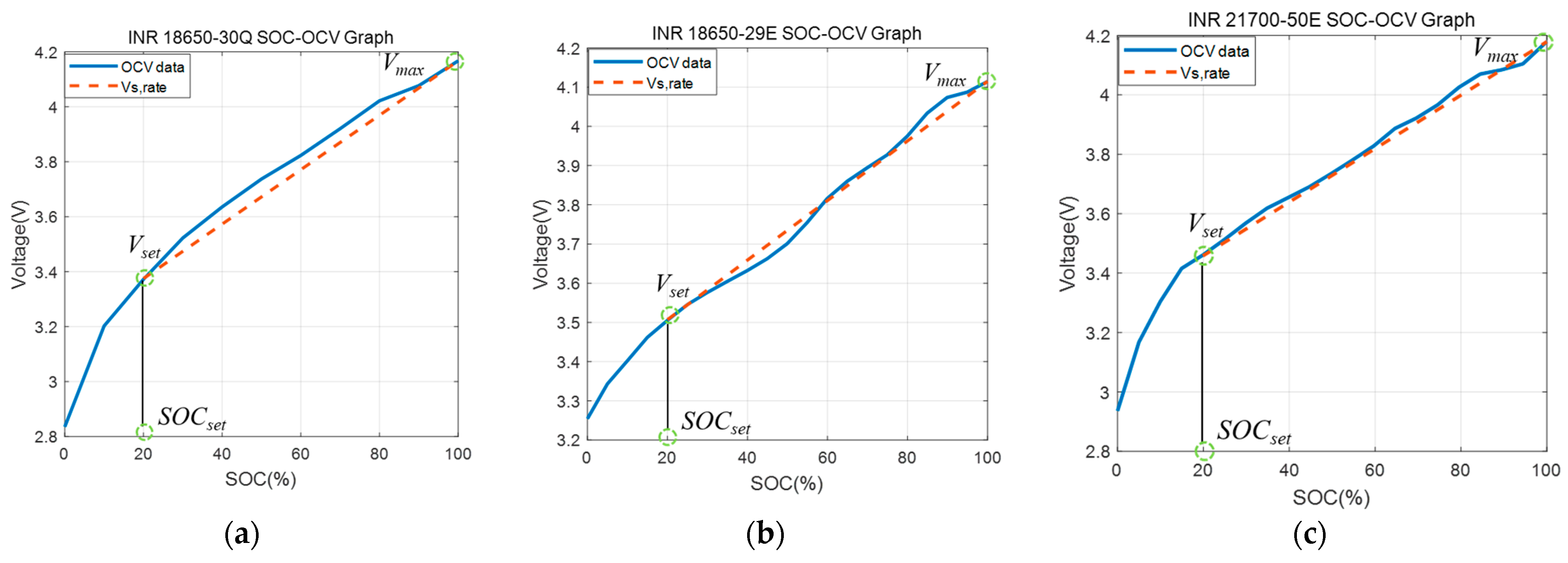
2.1. Balancing Voltage Deviation Determination

The proposed balancing method is a variable voltage deviation method in which the allowable voltage deviation between cells varies according to the voltage operating point of the battery. When a battery with a capacity of Ah and a state of charge of SOC is charged with Irated, which is the rated charging current, Tch, representing the time required to be fully charged, can be summarized as in Equation (1).
T c h = A h × ( 1 S O C ) I r a t e d × 3600
However, when charging proceeds while balancing a specific cell inside the battery pack, the cell is charged with a current reduced by the balancing current shown in Equation (2); thus, it is fully charged at the time shown in Equation (3), where Ibal represents the balancing current, Vnom is the nominal voltage of the battery, and Rbal is the balancing resistance.
I b a l = V n o m R b a l
T c h , b a l = I r a t e d ( I r a t e d I b a l ) × T c h
Assuming that the relationship between the battery SOC and voltage is linear, Vs,rate representing the voltage change rate per second can be expressed by Equation (4). In addition, when the battery is charged with the rated current, the time required to reach the full-charge voltage Vmax from Vset, which is the minimum voltage at which the balancing function operates, Tch,set, can be summarized using Equation (5). Therefore, the allowable voltage deviation threshold between cells at a specific operating point of the battery can be represented by Equation (6).
V s , r a t e = ( V m a x V s e t ) T c h , s e t
T c h , s e t = A h × ( 1 S O C s e t ) I r a t e d × 3600
V d i f f = ( T c h , b a l T c h , s e t ) × V s , r a t e
Therefore, if the voltage deviation between the cells at the full charge voltage of the battery is defined as Vdiff,target, the voltage deviation threshold (Vth) for the balancing operation can be designed as shown in Equation (7).
V t h = V d i f f , t a r g e t + V d i f f
Figure 2 shows the OCV-SOC and Vs,rate graphs of three types of batteries with different capacities and characteristics to show the voltage deviation design method described above. Vset, representing the lower limit voltage for performing the balancing operation, was selected at approximately 20% SOC to avoid a balancing operation at low SOC, where the deviation between battery cells is essentially significant.
The proposed variable voltage deviation method has the advantage of being able to design the voltage deviation between cells to be managed for each operating voltage of the battery when the capacity, OCV characteristics, and balancing resistance of the cell applied to the battery pack are known. Therefore, even when the battery cells are different, a voltage-deviation threshold for balancing can be systematically established. Figure 3 shows the variable voltage deviations for the three types of batteries with different capacities and characteristics according to the proposed method. At this time, the allowable voltage deviation target between cells at full charge voltage and the balancing resistor were set to 10 mV and 33 Ω, respectively, considering the specifications of the dedicated IC used for cell voltage monitoring and balancing [21]. In all three cases, as the operating voltage of the battery decreased, there was time to balance until the battery was fully charged, increasing the allowable voltage deviation between the cells. In addition, because the voltage deviation threshold was high at a low SOC, the balancing circuit operation was minimized at a low SOC.

2.2. Load Condition Determination for Balancing

The balancing algorithm consumes the energy of the corresponding cell through a resistor when the voltage deviation between the cells exceeds the threshold voltage. However, because the balancing operation affects the charge/discharge efficiency depending on whether it is a charge or discharge condition, it is necessary to determine the load conditions for balancing. Therefore, the effect of the balancing algorithm operation according to the charge/discharge/rest load conditions was analyzed using a simulation model of a reduced module with four INR 18650-30Q battery cells in series.
Research on various electrical equivalent circuit models (ECMs) to simulate the characteristics of lithium batteries has been conducted [22,23,24,25]. A lithium battery can be modeled by including an RC ladder in which a resistor and a capacitor are connected in parallel in addition to modeling represented by an open voltage source and a resistor [22]. At this time, the number of RC ladders affects the improvement of modeling accuracy, so it is determined by considering the accuracy and calculation amount. Additionally, J. Meng proposed a modeling method in which a resistance was added in parallel to the battery terminals mentioned above to detect the defect of the battery’s internal short circuit [26]. In this paper, since the analysis of the voltage management characteristics between cells according to the design of the balancing algorithm is being studied, a reduced module simulation model was designed using the electrical equivalent circuit cell model as shown in Figure 4. The battery cell can be represented by Equation (8). The open-circuit voltage is simulated by VOCV, and the Ri, Rdiff, and Cdiff parameters are used to simulate the dynamics of the voltage versus current. The ECM parameters according to the SOC of the battery cell are shown in Figure 5 and the detailed values are summarized in Table A1 in Appendix A. Additionally, the voltage accuracies of the MATLAB/Simulink battery simulation model to which the parameters were applied are shown in Figure 6. Figure 6 shows that the simulation model shows a voltage error of up to 0.18 V in low SOC with large nonlinearity, but it can simulate a real battery well within the root mean squared error (RMSE) error of 0.0121 V in the entire operating range of the battery.
V t e r m i a l = V O C V I R i I R d i f f ( 1 e t τ ) w h e r e , τ = R d i f f × C d i f f
To determine whether the balancing operation should be performed under a load condition among a charging process, discharging process, or rest condition, a simulation analysis using a reduction module including a balancing circuit and the algorithm shown in Figure 7 was performed. The parameters of each block in Figure 7 are shown in Table A4 of Appendix A. As shown in Table 2, an SOC deviation of 3%, capacity deviation of 1%, OCV deviation of 0.05%, and resistance deviation of 10% were set for one cell (cell #3) of the reduced battery module. The reduced battery module was fully discharged and charged.
Figure 8a shows the simulation results of balancing under the discharge conditions. A balancing loss energy of 0.24 Wh was generated to satisfy the target voltage deviation of 10 mV at the full charge point during the balancing operation under discharge conditions. Figure 8b shows the result of the balancing operation in the rest condition; a balancing loss of 0.53 Wh occurred to satisfy the target voltage deviation. Figure 8c is the result of the balancing operation under the charging condition; a balancing loss of 0.22 Wh was generated to satisfy the voltage deviation target of 10 mV. Table 3 summarizes the energy loss during one charge/discharge cycle according to the balance by the load condition.
The following conclusions were drawn from the simulation analysis of the three conditions to establish a balancing algorithm. First, balancing should not be performed during rest at low SOC. Even if the state of charge is the same at a low SOC, the voltage deviation between cells is significant, so the balancing operation can change the state of charge. This is confirmed by the simulation results in Figure 8b. Second, Figure 8a,c show that balancing at a specific voltage (set to 3.4 V in this case) or higher in the discharge or charge phase can manage the voltage deviation between the cells while consuming a similar level of energy. However, balancing during the discharging phase further reduces the usable energy of the battery, allowing balancing to be performed while the battery is charged, which can increase the usable energy. Therefore, based on this analysis result, an algorithm to balance above the variable voltage deviation threshold under charging conditions was designed, as shown in Figure 9.

3. Performance Analysis of the Proposed Method

This section analyzes the voltage management performance of the proposed balancing method for battery cell parameters and type variations through a simulation. In addition, by analyzing the efficiency of the proposed method and the balancing algorithms with a fixed voltage deviation presented in previous studies, it is suggested that the proposed method is equivalent to or better than the existing method.

3.1. Performance Analysis According to Parameter Deviation

Simulations reflecting the parameter deviations were performed in the INR 18650-30Q cell four-series reduced modules. As shown in Figure 10, the battery cell parameters were set by considering the parameter deviation of the cell measured in the experiment. At this time, the average value of the measured parameters was applied to the parameters of the three battery cells, and cell #4 was set to −1% capacity, +10% resistance, and +0.5% OCV compared to the average value, which was slightly higher than the deviation between the cells. In addition, the SOC of cell #4 was set to 1.5% higher than that of the other cells to generate an initial voltage deviation.
Figure 11 shows the simulation results of CC-CV charging (constant current–constant voltage) with a charging current of 0.5C-rate while the battery is fully discharged. Figure 11a shows the battery cell voltage, and Figure 11b shows the voltage deviation of the cell with the minimum and maximum voltages and the variable voltage deviation target value. Figure 11c shows the current of the battery module, and Figure 11d shows the balancing operation flag of each cell. The fully discharged battery is charged with the rated current, and balancing begins when the cell voltage reaches 3.4 V or higher, the SOC 20% point. Although there is a voltage deviation owing to a difference in the initial state of charge, the voltage is managed by the target variable voltage deviation as balancing is performed in the charging stage. As described above, the proposed balancing algorithm using variable voltage deviation can perform cell-to-cell voltage management well even under manufacturing deviation and differences in the state of charge of each cell used in the battery module.

3.2. Performance Analysis According to Battery Cell Type

This section presents the voltage management performance of the proposed balancing method when a reduced module using three cylindrical lithium batteries (INR 18650-30Q, INR 18650-29E, and INR 21700-50E) is fully charged at a current of 0.5C-rate. To facilitate the analysis of parameter deviation influence, the three cells of the reduced module set the same parameters and applied the parameter deviation to only one cell. The battery parameters used in the simulation are shown in Figure 5 for INR 18650-30Q, and in Figure 12 and Figure 13 for INR 18650-29E and INR 21700-50E, respectively. The detailed parameter values of Figure 12 and Figure 13 are summarized in Table A2 and Table A3. As shown in Table 4, the parameter settings of the reduced module to which the three cell types were applied were set to a slightly smaller capacity and a higher SOC for cell #4.
Figure 14a shows the charging simulation results of the reduced module using INR 18650-30Q. Voltage deviation of 50 mV exceeded at 3.4 V or less, which is not balanced due to SOC’s initial error. However, balancing is performed when the voltage deviation between cells exceeds the threshold voltage during charging; when the full charge voltage is reached, it can be confirmed that the voltage is controlled to the 10 mV target voltage.
Figure 14b shows the results of the charging simulation of the reduced module using INR 18650-29E. In the charging phase, balancing is performed because the target variable voltage deviation of 35 mV, indicated by the red dotted line, exceeds the 3.5 V voltage point. Compared with the other two batteries, the OCV characteristic of the 29E cell is that the voltage variation rate of the OCV increases rapidly depending on the state of charge (SOC); therefore, the voltage deviation is maintained for a long time, even after balancing. However, if balancing is performed up to the constant voltage (CV) control phase of the full-charge voltage, a target voltage deviation of 10 mV can be satisfied.
Figure 14c shows the simulation results of the reduced module using INR 21700-50E. As described above, if the 3.4 V voltage point is exceeded during charging, the balancing function operates, and the voltage deviation is maintained around the designed threshold range as the charging progresses.
When the proposed method is applied, even if the battery cells are changed, the voltage deviation between the cells can be managed stably by systematically designing the design variables of the balancing algorithm.

3.3. Efficiency Analysis of the Proposed Algorithm

This section analyzed the efficiencies of the proposed balancing method and the balancing method with a fixed voltage deviation. The simulation was performed under charging conditions, in which the INR 18650-30Q cell was fully charged in the fully discharged state of the 4-series reduced module. The passive balancing algorithm was set to perform a balancing operation when the voltage deviation was over 10 mV at 3.7 V or higher in the charging phase, considering the previous research results presented in Table 1. The battery cells of the reduced module used the parameters applied to Module 1, as listed in Table 4.
Figure 15a shows the voltage and current waveforms of the cells with parameter deviations as the battery module is charged in the cases of no balancing, balancing with a fixed voltage deviation, and balancing with the proposed variable voltage deviation. Figure 15b shows the maximum voltage deviation between the cells for each algorithm and the energy loss in the balancing resistance. As shown in the figure, the proposed balancing algorithm can maintain the voltage deviation of the cells within the target value at the fully charged voltage point, similar to the existing methods. In addition, it can be confirmed that the energy efficiency can be improved by approximately 2% (12 mWh) compared with the existing balancing method. This is because the proposed balancing algorithm avoids unnecessary balancing by allowing the voltage difference between the cells to reach the maximum voltage deviation corresponding to the voltage operating point.

4. Experiment Results

The proposed passive balancing algorithm was verified using a reduction module with four battery cells of three types connected in series, a charge/discharge cycler, and a BMS controller, as shown in Figure 16. The experimental setup consisted of a 30 V/10 A class battery charge/discharge cycler, DC1651A monitoring/balancing board with an LTC 6083 IC, Arduino controller in charge of external communication and balancing control logic, reduced battery module, and control/monitoring computer.
To analyze the feasibility of the proposed method, three of the four batteries were set to have the same state of charge, and one cell was additionally charged such that the maximum voltage deviation occurred at the corresponding battery operating voltage. The voltage deviation of each cell of the reduced module was managed using a balancing board, and the module was fully charged under CC-CV conditions.
Figure 17a shows the experimental results for the voltage, current, maximum voltage deviation between the cells, and balancing operation of the reduced module applied with INR 18650-30Q. Although there is a voltage of 50 mV between cells at the 3.4 V point, the proposed balancing algorithm operates during charging to maintain a target voltage deviation of 10 mV at the full charge voltage. Figure 17b shows the experimental results for the INR 18650-29E battery module. Although there is a maximum voltage deviation between the cells of 40 mV level at the 3.5 V point, the voltage deviation is reduced to 10 mV level at the full charge voltage by the proposed balancing algorithm. Figure 17c shows the experimental results obtained using the INR 21700-50E cell. Although there is a maximum voltage deviation between the cells of 30 mV at the initial point, the proposed balancing algorithm operates, and as charging progresses, the voltage deviation reaches the target voltage level of 10 mV. As described above, the balancing algorithm with variable voltage deviation proposed in this paper presents a design method capable of stably managing the voltage between cells, even when the battery cells are changed.

5. Conclusions

This study proposed a variable voltage deviation threshold design method for passive balancing when the specifications of the battery cell capacity, OCV characteristics, balancing resistance, and rated charging current are given. The proposed method can easily design and apply the algorithm even if the battery cell is changed because it presents a voltage deviation design method that reflects the primary characteristics of the cell applied to the battery pack.
In addition, the effect of the deviation of the parameters applied to the battery pack on the balancing performance was analyzed and presented. In this study, an experiment was conducted to measure the parameter deviation of the battery cell applied to the module. It was confirmed that the cells of three different types of cylindrical lithium batteries (INR 18650-30Q, INR 18650-29E, INR 21700-50E) had an initial deviation of 0.3% in capacity, 0.3% in OCV, and 5% in resistance. Through the balancing simulation of the reduction module reflecting the parameter deviation of the battery cell, it was confirmed that the proposed balancing method designed using the average value of the battery cell parameter does not affect the voltage deviation management performance. In addition, it was found through simulation that the balancing algorithm applying the proposed variable voltage deviation in the charging phase brought about an efficiency improvement equal to or more than 2% compared to the balancing algorithm with a fixed voltage. The proposed method was validated through simulations and experiments using a reduced battery module with three cylindrical lithium batteries in series.
However, the proposed method has a limitation in that it has been verified only for short-term charging and discharging conditions at room temperature. As the battery module continues to be charged and discharged, a difference in temperature and aging state between cells occurs. Therefore, after analyzing the aging and temperature distribution characteristics of each cell through long-term cycling experiments of the battery module, the performance of the proposed algorithm will be further analyzed.

Author Contributions

Conceptualization, S.L.; Methodology, H.S. and S.L.; Software, H.S.; Validation, H.S.; Formal analysis, H.S. and S.L.; Investigation, H.S.; Resources, S.L.; Data curation, H.S.; Writing—Original draft preparation, H.S.; Writing—Review and editing, S.L.; Visualization, H.S.; Supervision, S.L.; Project administration, S.L.; Funding acquisition, S.L. All authors have read and agreed to the published version of the manuscript.

Funding

This study was supported by a research fund from Chosun University (2019).

Conflicts of Interest

The authors declare no conflict of interest.

Appendix A

The battery cell parameters at 25 °C and 0.5 C-rate used in the simulation and experiment of this study are shown in Table A1, Table A2 and Table A3. Table A1 shows INR 18650-30Q parameters, Table A2 shows INR 18650-29E parameters and Table A3 shows INR 21700-50E parameters.
Table A1. INR 18650-30Q battery parameters.
SOCOCV (V)Ri (Ω)Rdiff (Ω)Cdiff (F)
100%4.1682 0.02190.03311058
90%4.0765 0.02190.03311058
80%4.0157 0.02130.02472476
70%3.91680.02120.04301507
60%3.82040.02060.0305898
50%3.73360.02130.02912451
40%3.63220.02140.03372007
30%3.52000.02080.03391680
20%3.35130.02150.03922525
10%3.20190.02190.0613610
0%2.82770.02330.0613610
Table A2. INR 18650-29E battery parameters.
SOCOCV (V)Ri (Ω)Rdiff (Ω)Cdiff (F)
100%4.11460.02700.01742318
90%4.07370.02660.01744330
80%3.97480.02730.02362366
70%3.89450.02680.03111878
60%3.81610.02660.03281780
50%3.70100.02630.02011232
40%3.63220.02700.02012849
30%3.57640.02700.02553425
20%3.50510.02680.02422603
10%3.40220.02800.02063039
0%3.25430.02880.06965361
Table A3. INR 21700-50E battery parameters.
SOCOCV (V)Ri (Ω)Rdiff (Ω)Cdiff (F)
100%4.17940.02810.01871616
90%4.08420.02760.01643237
80%4.02530.02740.02012924
70%3.92150.02740.02432113
60%3.82750.02760.01941506
50%3.73420.02720.01813108
40%3.65420.02750.02403359
30%3.56770.02760.02203219
20%3.46080.02830.01893556
10%3.30360.02890.03771648
0%2.93620.03230.05821215
The ECM parameters of the battery cell applied to the simulation model in Figure 7 are designed as a lookup table that outputs the values of Table A1, Table A2 and Table A3 for each SOC point. The battery is charged and discharged with CC discharge and CC-CV charge currents determined from blocks marked with a CC-CV Cycler. The parameters of the model block applied to Figure 7 are shown in Table A4.
Table A4. Parameters of simulation model.
ParametersValues
Battery
Cell
Model
OCVTable A1 for INR 18650-30Q
Table A2 for INR 18650-29E
Table A3 for INR 21700-50E
Ri
Rdiff
Cdiff
Cn3.0 Ah for INR 18650-30Q
2.66 Ah for INR 18650-29E
4.83 Ah for INR 21700-50E
CC-CV CyclerCC 1.5 A, CV 4.2 V (cutoff current 150 mA) for INR 18650-30Q
CC 1.25 A, CV 4.125 V (cutoff current 62.5 mA) for INR 18650-29E CC 2.5 A, CV 4.2 V (cutoff current 98 mA) for INR 21700-50E
Passive Balancing ModelIdeal Switch and balancing resistor (30 Ω)

References

  1. Ren, D.; Hsu, H.; Li, R.; Feng, X.; Guo, D.; Han, X.; He, X.; Gao, S.; Hou, J.; Li, Y.; et al. A comparative investigation of aging effects on thermal runaway behavior of lithium-ion batteries. ETransportation 2019, 2, 100034. [Google Scholar] [CrossRef]
  2. Ma, S.; Jiang, M.; Tao, P.; Song, C.; Wu, J.; Wang, J.; Deng, T.; Shang, W. Temperature effect and thermal impact in lithium-ion batteries: A review. Prog. Nat. Sci. Mater. Int. 2018, 28, 653–666. [Google Scholar] [CrossRef]
  3. Pesaran, A.; Santhanagopalan, S.; Kim, G.H. Addressing the Impact of Temperature Extremes on Large Format Li-Ion Batteries for Vehicle Applications (Presentation); No. NREL/PR-5400-58145; National Renewable Energy Lab (NREL): Golden, CO, USA, 2013. [Google Scholar]
  4. Petri, A.M.; Petreuș, D. Balancing and SOC Estimation in a Battery Management System for Electric Vehicle. In Proceedings of the IEEE 2021 44th International Spring Seminar on Electronics Technology (ISSE), Bautzen, Germany, 5–9 May 2021; pp. 1–6. [Google Scholar]
  5. Kutkut, N.H.; Divan, D.M. Dynamic equalization techniques for series battery stacks. In Proceedings of the IEEE Intelec’96-International Telecommunications Energy Conference, Boston, MA, USA, 6–10 October 1996; pp. 514–521. [Google Scholar]
  6. Lee, Y.; Jeon, S.; Lee, H.; Bae, S. Comparison on cell balancing methods for energy storage applications. Indian J. Sci. Technol. 2016, 9, 92316. [Google Scholar] [CrossRef] [Green Version]
  7. Habib, A.A.; Hasan, M.K.; Mahmud, M.; Motakabber, S.M.A.; Ibrahimya, M.I.; Islam, S. A review: Energy storage system and balancing circuits for electric vehicle application. IET Power Electron. 2021, 14, 1–13. [Google Scholar] [CrossRef]
  8. Omariba, Z.B.; Zhang, L.; Sun, D. Review of battery cell balancing methodologies for optimizing battery pack performance in electric vehicles. IEEE Access 2019, 7, 129335–129352. [Google Scholar] [CrossRef]
  9. Cao, J.; Schofield, N.; Emadi, A. Battery balancing methods: A comprehensive review. In Proceedings of the 2008 IEEE Vehicle Power and Propulsion Conference, Harbin, China, 3–5 September 2008; pp. 1–6. [Google Scholar]
  10. Abdul-jabbar, T.A.; Kersten, A.; Mashayekh, A.; Obed, A.A.; Abid, A.J.; Kuder, M. Efficient Battery Cell Balancing Methods for Low-Voltage Applications: A Review. In Proceedings of the 2022 IEEE International Conference in Power Engineering Application (ICPEA), Shah Alam, Malaysia, 7–8 March 2022; pp. 1–7. [Google Scholar]
  11. Hua, Y.; Zhou, S.; Cui, H.; Liu, X.; Zhang, C.; Xu, X.; Ling, H.; Yang, S. A comprehensive review on inconsistency and equalization technology of lithium-ion battery for electric vehicles. Int. J. Energy Res. 2020, 44, 11059–11087. [Google Scholar] [CrossRef]
  12. Kelkar, A.; Dasari, Y.; Williamson, S.S. A comprehensive review of power electronics enabled active battery cell balancing for smart energy management. In Proceedings of the 2020 IEEE International Conference on Power Electronics, Smart Grid and Renewable Energy (PESGRE2020), Cochin, India, 2–4 January 2020; pp. 1–6. [Google Scholar]
  13. Daowd, M.; Omar, N.; Van Den Bossche, P.; Van Mierlo, J. Passive and active battery balancing comparison based on MATLAB simulation. In Proceedings of the 2011 IEEE Vehicle Power and Propulsion Conference, Chicago, IL, USA, 6–9 September 2011; pp. 1–7. [Google Scholar]
  14. Hemavathi, S. Overview of cell balancing methods for Li-ion battery technology. Energy Storage 2020, 203, 1–12. [Google Scholar]
  15. Moore, S.W.; Schneider, P.J. A review of cell equalization methods for lithium ion and lithium polymer battery systems. SAE Tech. Pap. 2001, 2001, 01–0959. [Google Scholar]
  16. Bayati, M.; Abedi, M.; Farahmandrad, M.; Gharehpetian, G.B.; Tehrani, K. Important technical considerations in design of battery chargers of electric vehicles. Energies 2021, 14, 5878. [Google Scholar] [CrossRef]
  17. Thiruvonasundari, D.; Deepa, K. Optimized passive cell balancing for fast charging in electric vehicle. IETE J. Res. 2021, 69, 2089–2097. [Google Scholar] [CrossRef]
  18. Duraisamy, T.; Kaliyaperumal, D. Adaptive passive balancing in battery management system for e-mobility. Int. J. Energy Res. 2021, 45, 10752–10764. [Google Scholar] [CrossRef]
  19. Ismail, K.; Nugroho, A.; Kaleg, S. Passive balancing battery management system using MOSFET internal resistance as balancing resistor. In Proceedings of the IEEE 2017 International Conference on Sustainable Energy Engineering and Application (ICSEEA), Jakarta, Indonesia, 23–24 October 2017; pp. 151–155. [Google Scholar]
  20. Kıvrak, S.; Özer, T.; Oğuz, Y.; Erken, E.B. Battery management system implementation with the passive control method using MOSFET as a load. Meas. Control 2020, 53, 205–213. [Google Scholar] [CrossRef] [Green Version]
  21. Aizpuru, I.; Iraola, U.; Canales, J.M.; Echeverria, M.; Gil, I. Passive balancing design for Li-ion battery packs based on single cell experimental tests for a CCCV charging mode. In Proceedings of the IEEE 2013 International Conference on Clean Electrical Power (ICCEP), Alghero, Italy, 11–13 June 2013; pp. 93–98. [Google Scholar]
  22. Meng, J.; Luo, G.; Ricco, M.; Swierczynski, M.; Stroe, D.I.; Teodorescu, R. Overview of lithium-ion battery modeling methods for state-of-charge estimation in electrical vehicles. Appl. Sci. 2018, 8, 659. [Google Scholar] [CrossRef] [Green Version]
  23. Windarko, N.A.; Choi, J.H. SOC estimation based on OCV for NiMH batteries using an improved takacs model. J. Power Electron. 2010, 10, 181–186. [Google Scholar] [CrossRef] [Green Version]
  24. Miniguano, H.; Barrado, A.; Lázaro, A.; Zumel, P.; Fernández, C. General parameter identification procedure and comparative study of Li-Ion battery models. IEEE Trans. Veh. Technol. 2019, 69, 235–245. [Google Scholar] [CrossRef]
  25. Zhang, L.; Peng, H.; Ning, Z.; Mu, Z.; Sun, C. Comparative research on RC equivalent circuit models for lithium-ion batteries of electric vehicles. Appl. Sci. 2017, 7, 1002. [Google Scholar] [CrossRef] [Green Version]
  26. Meng, J.; Boukhnifer, M.; Diallo, D. On-line model-based short circuit diagnosis of lithium-ion batteries for electric vehicle application. In Proceedings of the IEEE IECON 2019-45th Annual Conference of the IEEE Industrial Electronics Society, Lisbon, Portugal, 14–17 October 2019; Volume 1, pp. 6022–6027. [Google Scholar]
Figure 1. Passive and active cell-balancing circuits: (a) Fixed-shunt resistor passive balancing, (b) switched-shunt resistor passive balancing, (c) buck–boost active balancing circuit, (d) flyback active balancing circuit.
Electronics 12 02587 g001aElectronics 12 02587 g001b
Figure 2. Algorithm design variables for a total of three types of batteries with different capacities; (a) INR 18650-30Q, (b) INR 18650-29E, and (c) INR 21700-50E.
Electronics 12 02587 g002
Figure 3. Allowable voltage deviation according to battery type.
Electronics 12 02587 g003
Figure 4. Equivalent electrical circuit model of lithium battery.
Electronics 12 02587 g004
Figure 5. Extracted battery parameters of INR 18650-30Q.
Electronics 12 02587 g005
Figure 6. Simulation modeling verification of INR 18650 30Q; (a) experimental and simulation voltage results, (b) battery current, and (c) modeling error rate.
Electronics 12 02587 g006
Figure 7. 4s1p battery module simulation model.
Electronics 12 02587 g007
Figure 8. Balancing operation results according to load conditions during (a) discharge, (b) rest, and (c) charge phases.
Electronics 12 02587 g008
Figure 9. Proposed passive balancing algorithm.
Electronics 12 02587 g009
Figure 10. Parameter deviation of INR 18650-30Q: (a) Capacity, (b) OCV, (c) Ri, and (d) Rdiff.
Electronics 12 02587 g010
Figure 11. Balancing algorithm operation results according to parameter error: (a) Cell voltages, (b) Cell voltage deviation and proposed variable deviation boundary, (c) Load Current, (d) Cells balancing on/off command.
Electronics 12 02587 g011
Figure 12. Extracted battery parameters of INR 18650-29E.
Electronics 12 02587 g012
Figure 13. Extracted battery parameters of INR 21700-50E.
Electronics 12 02587 g013
Figure 14. Simulation results of the proposed balancing method for each battery type (1st waveform: cell voltage, 2nd: voltage deviation, 3rd: load current, 4th: balancing operation flag); (a) INR 18650-30Q, (b) INR 18650-29E, (c) INR 21700-50E.
Electronics 12 02587 g014
Figure 15. Comparison of the efficiency of the proposed and existing algorithms: (a) cell voltage and current waveforms; (b) voltage deviation and balancing loss.
Electronics 12 02587 g015
Figure 16. Battery module experimental configuration.
Electronics 12 02587 g016
Figure 17. Experimental results of the proposed balancing method for each battery type (1st waveform: cell voltage, 2nd: charging current, 3rd: voltage deviation, 4th: balancing operation flag); (a) INR 18650-30Q, (b) INR 18650-29E, (c) INR 21700-50E.
Electronics 12 02587 g017
Table 1. Balancing algorithm operating conditions in previous studies.
Balancing AlgorithmCurrent
Condition
Voltage ConditionVoltage Threshold
D. Thiruvonasundari [17]Chargeabove 3.3 V25 mV
D. Thiruvonasundari [18]Chargeabove 3.9 V30 mV
K. Ismail [19]Chargeabove 3.55–3.6 V50 mV
S. Kivrak [20]Chargewhole range50 mV
Table 2. Simulation initial conditions.
ParameterInitial Condition
Cell #1, #2, #4Cell #3
SOC100%97%
Cn100% (3.0 Ah) 99%
OCVOCV parameter of Figure 5 +0.05% compared to other cells
Ri/RdiffRi, Rdiff/Cdiff parameters of Figure 5+10% compared to other cells
Table 3. Balancing loss according to current conditions.
Balancing ConditionBalancing Loss Energy during 1-CC/CV Cycle
Discharging0.24 Wh
Rest0.53 Wh
Charging0.22 Wh
Table 4. Battery simulation initial conditions.
Battery TypeParameterInitial Condition
Cell #1, #2, #3Cell #4
Module #1
with
INR 18650-30Q
SOC0%1.4%
Cn100% (3.0 Ah) 99%
OCVOCV parameter of Figure 5 +0.05% compared to other cells
Ri/RdiffRi, Rdiff/Cdiff parameters of Figure 5+10% compared to other cells
Module #2
with
INR 18650-29E
SOC0%1.4%
Cn100% (2.66 Ah) 99%
OCVOCV parameter of Figure 12+0.05% compared to other cells
Ri/RdiffRi, Rdiff/Cdiff parameters of Figure 12+8% compared to other cells
Module #3
with
INR 21700-50E
SOC0%1%
Cn100% (4.83 Ah) 99%
OCVOCV parameter of Figure 13+0.02% compared to other cells
Ri/RdiffRi, Rdiff/Cdiff parameters of Figure 13+8% compared to other cells
Disclaimer/Publisher’s Note: The statements, opinions and data contained in all publications are solely those of the individual author(s) and contributor(s) and not of MDPI and/or the editor(s). MDPI and/or the editor(s) disclaim responsibility for any injury to people or property resulting from any ideas, methods, instructions or products referred to in the content.

