Article

Image Recognition of Group Point Objects under Interference Conditions

by
Viliam Ďuriš
1,*,
Anatoly V. Grigoriev
2 and
Sergey G. Chumarov
2
1
Department of Mathematics, Constantine the Philosopher University in Nitra, Tr. A. Hlinku 1, 94901 Nitra, Slovakia
2
Department of Radio Engineering, I. N. Ulyanov Chuvash State University, 428015 Cheboksary, Russia
*
Author to whom correspondence should be addressed.
Electronics 2023, 12(11), 2537; https://doi.org/10.3390/electronics12112537
Submission received: 4 May 2023 / Revised: 27 May 2023 / Accepted: 2 June 2023 / Published: 4 June 2023
(This article belongs to the Special Issue Advances in Image Processing and Detection)

Abstract

:
The process of forming a vector-field model of flat images of group point objects, with various field-forming functions, is considered in this paper. Algorithms for recognizing group point objects in the presence of false and missing point objects are proposed. The quality of the recognition of group point objects by the proposed algorithms is also evaluated.

1. Introduction

Image processing problems involving clusters of point objects quite often arise in various technical applications. Typical examples of such objects are images of constellations on the celestial sphere, reference marks applied to products in automated lines, shiny dots in radar images of extended sections of the Earth’s surface, optical and radar images of sections of the celestial sphere containing space debris, models of human posture, etc. [1,2].
Consider an image containing k point objects Γ = { γ ( n ) } 0 , k , where n is the point number. The order of the dots in the image is determined by the way it is scanned. Each point object will correspond to one cell—the retina formed by the memory cells of the image (Figure 1a). In the graphic representation of the image, point objects are represented by a geometric point in the center of a square cell (Figure 1b). A more convenient representation is when point objects are located in the nodes of the retina; for this, a new retina is formed, the nodes of which are located in the centers of the cells of the old retina [3,4,5].
In general, point objects can occupy several retinal cells; in this case, we neglect the shape of the object and replace it with a geometric point—a representative of the object, such as its center of gravity [6].
We consider the retina as a discrete complex plane. In this case, a point object can be defined by a bundle of radius vectors B = β n 0 , k (Figure 1c), or by a chain of vectors X = x n 0 , k 2 (Figure 1d). In the first case, the origin is the pole O. Each point object is given by a complex-valued radius vector β ( n ) = β 1 ( n ) + j β 2 ( n ) , n = 0, 1, …, k − 1, connecting the point O with the point γ n (Figure 1c). In the chain representation, point objects are connected sequentially with each other by vectors x n = x 1 n + j x 2 n , n = 0,1 , , k 2 . The closure of the chain description forms a contour that gives the point object a shape. There are other representations of a collection of point objects, such as “Minimal tree”. The beams of radius vectors B and contour X are considered as complex-valued signals containing information about a point object, Γ [7].
High-resolution solid images with high densities require significant computing resources of the image processing system [8]. The refusal to process each element of the image stored in memory cells, and the transformation of solid images into a set of point objects, can significantly reduce the requirements for the computing system. The preprocessing of images for the given models of interaction of background and signal images makes it possible to best identify the most informative areas of the contour images [8]. The chain representation of a line describing a contour in the basis of elementary vectors, X = 1 j ; 1 ; 1 + j ; j ; 1 + j ; 1 ; 1 j ; j , sets a contour description with a resolution at the level of a storage device cell (Figure 2). The transition to the polygonal representation of the contour is obtained by approximating the contour with linear segments (Figure 2). The coding of the contour consists of fixing the coordinates of the ends of these segments.
A measure of the similarity of two complex-valued contours, X = x n 0 , k 1 and V = v n 0 , k 1 , where x n = x 1 n + j x 2 n and v n = v 1 n + j v 2 n , is their scalar product in the real E 2 k and complex C k spaces [7]:
X , V E 2 k = n = 0 k 1 x 1 n v 1 n + x 2 n v 2 n ,
X , V C k = X , V E 2 k j n = 0 k 1 x 2 n v 1 n + x 1 n v 2 n .
Due to the imaginary part, the product, X , V C k , is more informative. The scalar product of the contours of two rectangles rotated by 90 0 in the space E 2 k is zero; in the space C k , it is equal to the square of the contour modulus. Thus, in the second case, the correct decision is made about the similarity of the contours regarding the estimation of the contour rotation angle. Next, we denote the totality of the point object, Γ = γ n 0 , k , as a group point object (GrPO).
The disappearance of signal point objects, and the appearance of false ones in the GrPO, distorts the shape of the beam of the radius vectors B and contour X which, in turn, makes it difficult or practically impossible to correctly identify the GrPO. As a result, the search for a description of the GrPO that provides the best quality of processing in a complex interference environment, with acceptable computational costs, is the most urgent task considered in numerous sources. In [9], a model was used based on the conditional probability of the spatial–temporal gradient of the image given by a specific velocity model, and on the a priori geometry of the calculated field of motion that favors the boundaries of motion of the minimum length. A scale–space continuation can be used to enlarge the capture region surrounding a feature [10]. Snakes provide a unified account of a number of visual problems, including the detection of edges, lines, and subjective contours, motion tracking, and stereo matching. The use of the wavelet transform [11] in the processing of images of nanoparticles obtained by the dynamic scattering method increases the resolution of the method and creates better images [12]. The methods of merging images in the frequency domain have been considered [13,14]. The practical applications of image processing methods are discussed in [15,16,17,18,19].
We note the wide variety of methods and approaches to solving image processing problems and the successes achieved in this area, especially with the help of neural network algorithms. However, the high computational requirements of these approaches and the difficulties of implementing algorithms for mobile platforms stimulate the search for more cost-effective methods based on a well-developed theory of processing radio signals. The vector-field GrPO model, which is a contour on a complex plane, is resistant to interference [20].

2. Research Methods

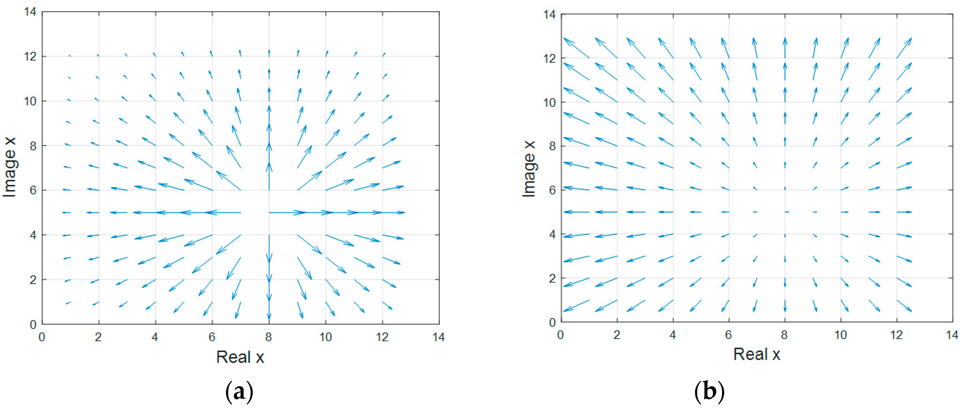
2.1. Vector-Field Model of a Flat Image of a GrPO

The formation of the vector-field model of a GrPO is based on the placement of single charges in the positions of the point marks, Γ = γ ( n ) 0 , k 1 , of the image, creating a force field, H n , the intensity of which is determined by the module, H n . As a result:
H n , m = f x n , m , x n , m = x n , m e x p j θ n , m , n , m = 0,1 , , k 1 , n m ,
where x n , m = β m β n is the vector connecting the point γ ( n ) with the point γ ( m ) ; β n is the radius vector drawn from the origin or center of mass of the point object to the point with the coordinate γ ( n ) ; and f is a function describing the field change in the plane of the image. The set of vectors x n , m connecting the point marks of the GrPO forms a contour X = x n 0 , k 1 , and the radius vectors connecting the origin and point marks form a bundle of vectors B = β n 0 , k 1 .
The process of forming the vector of field, H n , m , at point, γ ( m ) , is defined as follows:
H n , m = H n , m e x p j θ n , m , n , m = 0 , 1 , , k 1 , n m
Let us explain this with an example calculating the vector of the field created by a charge placed at the point, γ n = 1 + 1 j , at a point with the coordinates γ m = 4 + 1 j (Figure 3). The charge creates a field whose intensity decreases with distance according to the law:
H n , m = e x p x n , m 2 2 σ 2
In the case of σ = 4 , expression (3) gives H n , m = e x p x n , m 2 32 . The vector, x n , m , is defined as the difference between the radii of the vectors β m and β n . For the given coordinates of the points γ ( n ) and γ ( m ) , we have x n , m = 4 + 1 j 1 + 1 j = 3 . The field intensity modulus at a point with coordinates γ m = 4 + 4 j , according to expression (3), is equal to H n , m = 0.7548 , and the argument of the field vector at the point, γ m , is equal to a r g H n , m = arg x n , m = θ n , m = 0 . Using expression (2), we find the desired vector H n , m = 0.7548 .
The calculation of vector fields of unit charge, γ ( n ) , with a radius vector equal to β n = 8 + 5 i in the cases of exponential H n , m = e x p x n , m 2 32 and linearly increasing H n , m = x n , m laws of variation of the field intensity, is shown in Figure 4.
The vector-field model H ^ = H ^ n 0 , , l 1 of a GrPO consists of l -many vectors of the resulting field specifying the code of this object [20]:
H ^ n = m = 0 , m n l 1 H n , m e x p j θ n , m , n , m = 0,1 , , l 1 ,
where H n , m is defined by expressions (1) and (2).
Each vector, H ^ n , is equal to the value of the field at the point γ ( n ) , created by the other l 1 -many point objects of the GrPO, except for the charge of the point object, γ ( n ) , for which the elementary vector of the vector-field model is determined. The vectors, H ^ n , forming the vector-field description are complex numbers, and the modulus, H ^ n , is determined by the total effect of vector fields created by all charges placed in point objects, γ n , n = 1 , , l 1 , within the image.
Let us consider an example of the formation of a vector-field model H ^ = H ^ n 0,3 , a group point object Γ = γ ( n ) 0,3 , given by radius vectors β n = 6 + 0 j , 3 3 j , 1 + 1 j , 2 + 7 j relative to the pole O (Figure 5). The positions of point objects Γ = γ ( n ) 0,3 , are marked with blue circles. The calculation of the vectors, H ^ n , and vector-field model, H ^ = H ^ n n = 0 , , l 1 , in the case of the Gaussian law of field intensity variation with σ = 4 , carried out using expression (4), gives the vectors: H ^ 0 = H 1,0 + H 2,0 + H 3,0 = 2.5720 0.4552 j ;   H ^ 1 = H 0,1 + H 2,1 + H 3,1 = 1.4388 2.1261 j ;   H ^ 2 = H 0,2 + H 1,2 + H 3,2 = 0.3595 + 0.0558 j ; and H ^ 3 = H 0,3 + H 1,3 + H 2,3 = 0.7738 + 2.5255 j . Thus, each vector, H ^ n , n = 0 , , 3 , is equal to the value of the field at the point, γ ( n ) , created by the charges of the other three points of the GrPO. The charge of the point, γ ( n ) , is not taken into account in the calculation of the vector, H ^ n . The concatenation of the obtained vectors, H ^ n , forms a contour, H ^ (Figure 5), which is a description of the GrPO based on a vector-field model. The resulting description has advantages over the contour formed by the junction of the ends of the radius vectors β n .
The initial description of the GrPO in the form of a radius beam β n carries information about the position in the plane of the image of individual POs, while the contour X = X n n = 0 , , l 1 , connecting point objects, γ ( n ) , gives information about the relative positions of neighboring point markers. The vector-field model contains, in each vector H ^ n , information about all the POs in the image, which ensures the stability of the description in the appearance of false POs and the disappearance of signals [20,21].
It should be noted that the contour of the vector-field model is closed, which manifests itself in the equality of the sum of all vectors, H ^ n , of the contour of the vector-field model to zero.
n = 0 l 1 H ^ n = 0
The properties of the contour description of the vector-field model [20,21]:
  • The rotation of all GrPO points by a certain angle, Δ φ , leads to the rotation of the contour, H ^ , by the same angle.
  • An offset by d of the origin of the GrPO points will lead to a similar offset of the origin of the contour, H ^ .

2.2. Recognition of GrPOs by Vector-Field Models

The contour, H ^ = H ^ n n = 0 , , l 1 , formed on the basis of a vector-field model contains information about the mutual position of point objects of a GrPO, on the basis of which the problems of its recognition are solved. In general, the applied Gaussian field-forming function (3) is a nonlinear transformation of the elementary vectors of the initial beam of vectors in the form of an additive mixture of the GrPO and normally distributed radius vectors of coordinate noise. A summing at each point, γ ( n ) , of the field vectors, H ^ n , m , normalizes the distribution of the interference of the final description according to the central limit theorem of probability theory. The use of the most powerful decision rules based on the likelihood function make it possible to use their scalar product as a measure of the similarity of contours [20,21]:
H ^ , E ^ = n = 0 l 1 H ^ n E ^ s , n * , s = 0 , 1 , , M 1 ,
where E ^ s , n * is the n -th contour vector of the vector-field model of the GrPO of the s -th class, and * denotes complex conjugation.
The modulus of the scalar product of the signal and reference circuits, H ^ Δ φ , E ^ s , is invariant to the rotation of the GrPO image by an arbitrary angle, Δ φ , as a result of which it acts as a measure of the similarity of the contours in the absence of a priori information about the rotation of the signal GrPO by Δ φ .
The magnitude of the scalar product of the contours of the vector-field model H ^ , E ^ depend on the shift of the initial point of the signal and reference GrPO by an arbitrary value, d . The cyclic calculation of the scalar product of contours, H ^ d , E ^ s , with shifts in the starting point of the reference GrPO vector-field model, forms a scan of the counts of the mutual correlation function, the maximum value of which is formed when the initial points of the contours coincide. This procedure is performed using a contour matched filter [7]:
η d = n = 0 l 1 H ^ n E ^ s , n d + k 1 * , d = 0 , 1 , , M 1 .
Let d 0 be the reference number at which the modulus of expression (7) becomes maximal; then, the value, η d 0 , is a measure of the similarity of two GrPOs, invariant to the shift of their initial points and the angle of mutual rotation, i.e.,
η d 0 = I n v Δ φ , d .
The normalization of the corresponding signal and reference contours eliminates the influence of image scales on the output signal module of the contour-matched filter [20,21].
Based on the above, the algorithm of the recognition device is as follows:
  • Reference vector-field descriptions of the GrPO are formed.
  • Based on the localized and numbered GrPO image, its vector-field model is calculated.
  • This vector-field model is compared with each reference model. The similarity measure is the output signal of the contour-matched filter (8). A prerequisite for solving the recognition problem is that the recognized GrPO belongs to one of the reference classes.
  • The recognized one is the GrPO, for which η d 0 reaches the maximum.

2.3. Field-Forming Functions

The properties of vector-field models depend significantly on the distribution of the vector field [22]. The following field-forming functions are most often used:
  • Gaussian:
    H n , m = μ e x p x n , m 2 2 σ 2
This function has two parameters: scale, μ , and rate of decreasing field intensity, σ . The selection of these parameters affects the localization of the GrPO and, accordingly, the form of the description. A decrease in σ leads, on the one hand, to the selection of the most closely spaced POs, which reduces the sensitivity to the appearance of false marks; on the other hand, the sensitivity to coordinate noise increases due to a decrease in the number of POs involved in the formation of the model.
2.
Constant field intensity:
H n , m = c o n s t .
This eliminates the influence of scale on the shape of the GrPO. The generated model is determined only by the direction of interaction.
3.
Linear increase in field intensity:
H n , m = x n , m
The linear nature of this dependence makes the transformation invariant to scaling; the increasing nature highlights the POs located in the most remote areas of the image, excluding the central point objects.
4.
Hyperbolic decrease in field intensity:
H n , m = 1 / x n , m
This is similar to a Gaussian function, and the shape of the field contour is preserved when the scale is changed.
The vector-field graphs, in the case of exponential and linearly increasing field-forming functions of a point object, γ(n) = 5 + 8j, are shown in Figure 4a,b, with uniform and hyperbolic field intensity shown in Figure 6a,b.

2.4. Numbering of GrPO Points

The position of the point marks in the plane of the image is determined by two coordinates, as a result of which there is uncertainty in the order of the point marks in the GrPO; this, in turn, leads to the problem of the optimal numbering of GrPO points. The arbitrary ordering of the point objects destroys the GrPO by making the connections between them random. The algorithm for ordering point marks in the plane of the image forms a new representation of the GrPO and affects the quality of recognition. The essentially nonlinear nature of this procedure should be noted.
There are various approaches to the ordering of point objects [20,23]. In this article, an approach based on natural numbering is used as it provides the lowest probability of an erroneous solution, and we compare this with ordering the vectors by their length (modulus). In both cases of numbering, a bundle of radius vectors, β n 0 , l 1 , is constructed connecting the center of gravity of the GrPO with each of the points, γ n . The initial number is assigned to the point, γ n , with the vector of maximum radius. Further numbering takes place in the ascending or descending order of the angle between the current radius vector and the radius vector of the maximum length. An example of the natural numbering of a GrPO (Figure 5) is shown in Figure 7.

3. Results

We evaluated the stability of the GrPO recognition algorithm in the form of a vector-field model regarding the effects of coordinate noise, the appearance of false point objects, and missing point objects. An evaluation of computational complexity at this stage is not within the scope of this work. The measure of similarity of the contours of the vector-field model, H ^ = H ^ n n = 0 , , l 1 , is the scalar product of the signal and reference contours [20]. The modeling of algorithms and construction of recognition characteristics were carried out in the Matlab environment by implementing the general algorithm shown in Figure 8.
The modeling process was divided into the following stages:
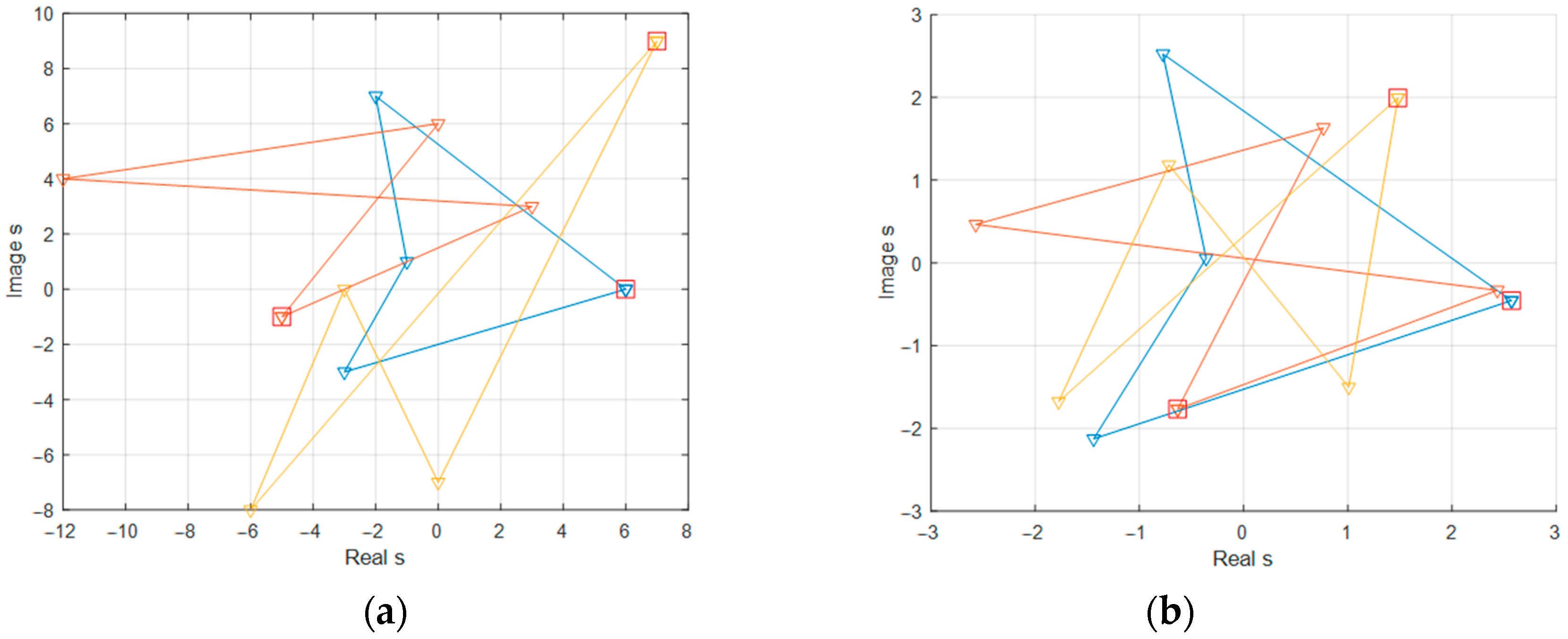
  • The formation of a bank of reference and signal GrPOs localized in the plane of the image, with the construction of a vector-field model. The simulation of the location of GrPO points was carried out by generating an array of quasi-random numbers obeying a normal distribution. The initial data in the process of obtaining the reference contours of the vector-field model were as follows: size of the image, 10 × 10 ; number of reference point objects, 3; and dimension of point objects, 4. In the Matlab application software package, images of the reference GrPO Γ 1 , Γ 2 , Γ 3 are constructed (Figure 9a). Visual separation of GrPO Γ 1 , Γ 2 , Γ 3 is carried out using a color scheme. The positions of the point objects γ n 0,3 of each reference GrPO are marked with triangular markers, the starting points are square. The lines connecting the point objects form the contours X 1 , X 2 , X 3 corresponding to the chain representation of the GrPO. The contours of the vector-field models H ^ 1 , H ^ 2 , H ^ 3 of the reference GrPO Γ 1 , Γ 2 , Γ 3 (Figure 9a) are formed using expression (4) in the Matlab environment. The images of the contours of the reference vector-field models H ^ 1 , H ^ 2 , H ^ 3 are constructed in Matlab (Figure 9b). The color scheme of the contours of the vector-field models H ^ 1 , H ^ 2 , H ^ 3 , marking the starting point of the contour and the ends of the vectors forming the contour corresponds to the designation GrPO Γ 1 , Γ 2 , Γ 3 (Figure 9a). The signal GrPO was obtained by shifting the starting point, d , scaling factor, μ , and rotation angle, Δ φ , of the reference radius vectors of the reference vector of the signal GrPO. In order to simplify modeling, we set the zero shift of the starting point, d = 0 , a scale of μ = 1 , and a rotation angle of Δ φ = 0 .
  • The creation of an interference situation caused by coordinate noise with contour, Z , along with the omission of signals, γ x n , and the appearance of false marks, γ z n . This study was carried out within the framework of an additive model defined by the expression, Y = X + Z , where Y is the contour of the noisy GrPO, X is the contour of the signal GrPO, and Z is the noise contour. The level of coordinate noise was set in the source data as the value of the signal-to-noise ratio by converting to the standard deviation using the expression:
    σ = X 2 / 1 q l 1 / 2 ,
    where q is the signal-to-noise ratio.
The values of the signal-to-noise ratio in the construction of recognition characteristics were selected in the range from 0.1 to 100. The number of missing point objects was determined by the probability of missing the signal, and the numbers of deleted GrPO point markers were determined using a random number generator obeying a uniform distribution.
The size of the image and the specified false alarm probability level determined the number of false point objects added to the scene. We considered two variants of the location of false point objects in a noisy scene: a compact arrangement of false and signal point markers and a mixed one. The first variant was obtained by the concatenation of two matrices of point marks γ x n and γ L n ; in the mixed variant, the elements of the combined matrix were ranked according to certain characteristics. The suboptimal nature of the vector-numbering algorithm leads to the mixing of signal GrPO points and false marks with the permutation of signal GrPO vectors.
3.
The normalization and centering of the reference, E ^ , and signal, H ^ , contours of the vector-field model allows us to eliminate the uncertainty caused by scaling the contours. The reference contour, E ^ , corresponding to the signal contour, H ^ , in the adopted implementation, Y , was selected as the reference contour, Y ^ .
4.
The recognition of the signal GrPO. The best noise immunity, when recognizing a GrPO against a background of coordinate noise, is provided by a contour-matched filter (6) that maximizes the signal-to-noise ratio at its output. The direct calculation of the correlation function by the filter is limited by the following factors:
  • The discrepancy between the dimensions of the reference contour and the signal one due to the appearance of false marks and the disappearance of signal marks;
  • The violation of the order of the point marks in the signal circuit as a result of the ordering of point marks.
The presence of a priori information about the possible angle of rotation of the contour makes it possible to simplify the recognition algorithm by limiting the calculation of the real part of the normalized scalar product:
η d = R e H ^ d , E ^ * H ^ d E ^ * .
The modeling of the GrPO recognition problem using a vector-field model, in the absence of missing or false point marks with the initial data given in stages 1 and 2, ends with the construction of recognition characteristics (Figure 10). Four field-forming functions were used: Gaussian with the parameter σ = 10 , uniform, linearly increasing, and hyperbolic. The reference GrPO used in the test images is shown in Figure 9a, and the bank of reference vector-field models formed from it is shown in Figure 9b.
The nature of the dependence of the probability of the correct recognition of PD on the signal-to-noise ratio, q , (Figure 10) allows us to conclude that the vector-field description of the GrPO is sufficiently stable under various interference conditions. In the absence of false or missing marks (Figure 10a), the recognition characteristics with the accepted field-forming functions under the conditions of coordinate noise show approximately the same recognition quality. A slight difference in the nature of the behavior of the graphs is related to the form of the particular GrPO. The appearance of missing signals and false point objects leads to a deterioration in the quality of recognition (Figure 10b–d), which is associated with a distortion of the shape of the signal GrPO compared to the reference image. The nature of the location of false and missing point objects relative to the center of gravity of the GrPO affects the qualitative recognition indicators with specific field-forming functions.
The discrepancy between the dimensions of the signal and reference circuits was solved in several ways. In the simplest case of solving the recognition problem, the noisy contour of the vector-field model, Y ^ , or the reference, E ^ , was supplemented with zero vectors until the contour dimensions coincided. The recognition characteristics for this case are shown in Figure 10. Compensating for the disappearance of missing point objects allows an approach in which a sweep of correlation functions is formed between the noisy contour, Y ^ , and the reference field contours, E ^ m , when vectors, E ^ n , m , of the reference contours are added to the noisy contour, Y ^ . If false point objects appear in the scene, the vectors, Y ^ n , m , of the noisy contour are deleted. A reasoned decision on the class number gives the maximum value of the response of the contour-matched filter in the procedure of sorting the dimensionally aligned contours. This method provides recognition quality comparable to that in the absence of false or missing point marks. At the same time, the practical application of this method is limited by an excessively large amount of calculations, which increase with an increase in the number of standards, the dimension of the contour, the probability of a false alarm, and signal skipping.
In case of violation of the order of the point marks in the signal circuit, a procedure for ordering the vectors of the signal and reference circuits is necessary. The characteristics of recognition in the absence of false and missing point objects are shown in Figure 11.
It should be noted that there is a general deterioration in the quality of recognition in the presence of only coordinate noise in comparison with the characteristics for the normal following of the signal loop vectors. The reason for this is the lack of a priori information about the possible order of the point objects, which leads to a suboptimal ranking of vectors. Among the presented methods, natural numbering should be highlighted as providing better recognition characteristics compared to the Y ^ n modulus ranking method. The nature of the distributions of the graphs with various field-forming functions (Figure 11) indicates the influence of the distance of point objects from the figure’s center of gravity. A linearly increasing function is preferred for GrPOs in which point objects are maximally removed from the center of gravity of the figure; hyperbolic and Gaussian, on the contrary, are preferred for GrPOs in which point objects form clusters in the center of the mass, while uniform assumes the same density of distribution of the POs along the plane of the image.
It is possible to reduce the influence of violation of the sequence order of point objects in the signal contour of the vector-field model, Y ^ , by abandoning contour-matched filtering and switching to a vector comparison of contours [20]. In this case, the integral nature of the vector-field model is taken into account, since each vector carries information about all the vectors of the GrPO. In this case, the optimality of the recognition procedure is violated in comparison with the formation of a scalar product of contours.

4. Conclusions

The vector-field model of flat GrPO images considered in this paper carries information about all point objects in the plane of the image due to the integral effect during its formation. This, in turn, ensures the stability of the GrPO description when coordinate noise, signal loss, and the appearance of false marks are present. The constructed recognition characteristics, if the order of the vectors of the field contour is observed, show high resistance to interference conditions.
Approaches were proposed herein to overcome the dimensional inequality of the signal and reference contours of vector-field models. The first approach involves the alignment of dimensions by adding zero vectors to the signal or reference contour; the second, in the case of a smaller dimension of the signal contour compared to the reference, involves borrowing the missing vectors in the reference bank, or, in the case of the signal dimension exceeding that of the reference contour, sequentially removing the vectors of the signal contour. A scan of scalar products is formed for all possible combinations of borrowed or deleted vectors in the search for the extreme value of the similarity measure. The decision is made in favor of the reference GrPO that has the maximum value.
It should be noted that, the quality of recognition deteriorates when the order of the POs in the vector-field contour is violated. The applied ordering algorithms ensure the quality of recognition only in cases of a simple interference situation, which leads to the problem of finding the best ranking algorithm.

Author Contributions

Conceptualization, V.Ď.; data curation, S.G.C.; formal analysis, V.Ď.; investigation, A.V.G.; methodology, S.G.C.; resources, A.V.G.; supervision, V.Ď.; validation, S.G.C.; visualization, A.V.G. All authors have read and agreed to the published version of the manuscript.

Funding

This study received no external funding.

Data Availability Statement

Not applicable.

Conflicts of Interest

The authors declare no conflict of interest.

References

  1. Witman, R.L.; Rear, R.L.O. Automating clustering of synthetic aperture radar (SAR) targete. IEEE. Naecon. 1980, 3, 717–724. [Google Scholar]
  2. Krajčovič, S.; Šilha, J.; Zigo, M.; Ďurikovič, R. The Image Processing System for Ultra-Fast Moving Space Debris Objects. Arab. J. Sci. Eng. 2023, 1–6. [Google Scholar] [CrossRef]
  3. Frank, Y.S. Mathematical Morphology. In Image Processing and Pattern Recognition: Fundamentals and Techniques; IEEE: Piscataway, NJ, USA, 2010; pp. 63–118. [Google Scholar] [CrossRef] [Green Version]
  4. Li, Z.N.; Drew, M.S.; Liu, J. Graphics and Image Data Representations. In Fundamentals of Multimedia; Springer: Berlin/Heidelberg, Germany, 2014; pp. 57–80. ISBN 978-3-319-05289-2. [Google Scholar] [CrossRef]
  5. Li, Z.; Ma, L.; Chen, M.; Xiao, J.; Gu, Q. Patch Similarity Aware Data-Free Quantization for Vision Transformers. In Computer Vision—ECCV 2022; Lecture Notes in Computer Science; Avidan, S., Brostow, G., Cissé, M., Farinella, G.M., Hassner, T., Eds.; Springer: Berlin/Heidelberg, Germany, 2022; p. 13671. [Google Scholar] [CrossRef]
  6. Burger, W.; Burge, M.J. Image Matching and Registration. In Digital Image Processing; Springer: Berlin/Heidelberg, Germany, 2016. [Google Scholar] [CrossRef]
  7. Furman, Y.A.; Krevetsky, A.V.; Peredreyev, A.K.; Rozentsov, A.A.; Hafizov, R.G.; Yegoshina, I.L.; Leukhin ANFurman, Y. Contour Analysis Introduction and Its Image and Signal Processing Application. In International Academic Publishing Company “Nauka”; Russian Academy of Sciences: Moscow, Russia, 2002; 592p. [Google Scholar]
  8. Qiao, W.; Zhao, Y.; Xu, Y.; Lei, Y.; Wang, Y.; Yu, S.; Li, H. Deep learning-based pixel-level rock fragment recognition during tunnel excavation using instance segmentation model. Tunn. Undergr. Space Technol. 2021, 115, 104072. [Google Scholar] [CrossRef]
  9. Cremers, D.; Soatto, S. Motion Competition: A Variational Approach to Piecewise Parametric Motion Segmentation. Int. J. Comput. Vis. 2005, 62, 249–265. [Google Scholar] [CrossRef] [Green Version]
  10. Martin, P.; Refregier, P.; Goudail, F.; Guerault, F. Influence of the noise model on level set active contour segmentation. IEEE Trans. Pattern Anal. Mach. Intell. 2004, 26, 799–803. [Google Scholar] [CrossRef] [PubMed]
  11. Ďuriš, V.; Semenov, V.I.; Chumarov, S.G. Wavelets and digital filters designed and synthesized in the time and frequency domains. Math. Biosci. Eng. 2022, 19, 3056–3068. [Google Scholar] [CrossRef] [PubMed]
  12. Ďuriš, V.; Chumarov, S.G.; Mikheev, G.M.; Mikheev, K.G.; Semenov, V.I. The Orthogonal Wavelets in the Frequency Domain Used for the Images Filtering. IEEE Access 2020, 8, 211125–211134. [Google Scholar] [CrossRef]
  13. Zhang, P.; Wang, L.; Eslami, H. A Mathematical Model of PCNN for Image Fusion with Non-Sampled Contourlet Transform. In Applied Mathematics and Nonlinear Sciences; Sciendo: Warsaw, Poland, 2022. [Google Scholar] [CrossRef]
  14. Yang, X.; Zeng, J.; Xu, C.; Peng, L.; Alsultan, J. Modeling of Fractional Differential Equation in Cloud Computing Image Fusion Algorithm. In Applied Mathematics and Nonlinear Sciences; Sciendo: Warsaw, Poland, 2022. [Google Scholar] [CrossRef]
  15. Aram, M.; Abessi, O. Optimal design of green buildings using computational fluid dynamics and climate simulation tools. Int. J. Environ. Sci. Technol. 2019, 17, 917–932. [Google Scholar] [CrossRef]
  16. Cai, W. Chinese Painting and Calligraphy Image Recognition Technology Based on Pseudo Linear Directional Diffusion Equation. In Applied Mathematics and Nonlinear Sciences; Sciendo: Warsaw, Poland, 2022. [Google Scholar] [CrossRef]
  17. Dharmik, R.C.; Chavhan, S.; Gotarkar, S.; y Pasoriya, A. Rice quality analysis using image processing and machine learning. 3C TIC. Cuad. Desarro. Apl. A Las TIC 2022, 11, 158–164. [Google Scholar] [CrossRef]
  18. Paikrao, P.; Doye, D.; Bhalerao, M.; Vaidya, M. Verification of role of data scanning direction in image compression using fuzzy composition operations. 3C Tecnología. Glosas Innovación Apl. A Lapyme 2022, 11, 38–49. [Google Scholar] [CrossRef]
  19. Paikrao, P.; Doye, D.; Bhalerao, M.; y Vaidya, M. Near-lossless compression scheme using hamming codes for non-textual important regions in document images. 3C TIC. Cuad. Desarro. Apl. A Las TIC 2022, 11, 225–237. [Google Scholar] [CrossRef]
  20. Furman, Y.A.; Krevetsky, A.V.; Rozentsov, A.A.; Hafizov, R.G.; Leukhin, A.N.; Yegoshina, I.L. Complex and Hypercomplex System at Tasks of Multidimensional Signal Processing; Fizmatlit: Moscow, Russia, 2023; p. 456. [Google Scholar]
  21. Rozentsov, A.; Evdokimov, A.; Grigoriev, A. Recognition of flat images of group point objects in the presence of detection errors. Instrumentation 2006, 49, 59–64. [Google Scholar]
  22. McNally, W.; Vats, K.; Wong, A.; McPhee, J. Rethinking Keypoint Representations: Modeling Keypoints and Poses as Objects for Multi-person Human Pose Estimation. In Computer Vision—ECCV 2022; Lecture Notes in Computer Science; Avidan, S., Brostow, G., Cissé, M., Farinella, G.M., Hassner, T., Eds.; Springer: Cham, Switzerland, 2022; p. 13666. [Google Scholar] [CrossRef]
  23. Berry, K.J.; Kvamme, K.L.; Johnston, J.E.; Mielke, P.W., Jr. Permutation Statistical Methods. In Permutation Statistical Methods with R; Springer: Cham, Switzerland, 2021; ISBN 978-3-030-74360-4. [Google Scholar] [CrossRef]
Figure 1. Image with point objects: (a) representation of a binary image of point objects on a square retina, (b) setting point objects with a geometric point in the center of the cell, (c) setting point objects with complex-valued radius vectors, (d) chain representation of the image of point objects.
Electronics 12 02537 g001aElectronics 12 02537 g001b
Figure 2. Polygonal representation of a contour as a result of contour approximation by linear segments.
Electronics 12 02537 g002
Figure 3. Construction of the vector of field, H n , m , at point, γ m , created by the charge placed at point γ n .
Electronics 12 02537 g003
Figure 4. Vector fields in the case of (a) an exponential field; (b) a linearly increasing field.
Electronics 12 02537 g004
Figure 5. Formation of the contour of the vector-field model GrPO Γ = γ ( n ) 0,3 .
Electronics 12 02537 g005
Figure 6. Vector fields in the case of (a) uniform and (b) hyperbolic fields.
Electronics 12 02537 g006
Figure 7. Numbering of GrPO points via natural numbering.
Electronics 12 02537 g007
Figure 8. Algorithm for modeling the GrPO recognition problem using a vector-field model.
Electronics 12 02537 g008
Figure 9. Contours of the GrPO: (a) the initial localization and (b) the bank of formed contours of vector-field models with a Gaussian field-forming function in the case of σ = 30 .
Electronics 12 02537 g009
Figure 10. Characteristics of GrPO recognition using a vector-field model with a compact arrangement of the signal and reference contours in the case of (a) the absence of false or missing marks; (b) the addition of 3 false POs; (c) the absence of false POs and the disappearance of 1 signal PO out of 4; and (d) the addition of 3 false POs and the disappearance of 1 signal PO.
Electronics 12 02537 g010aElectronics 12 02537 g010b
Figure 11. Characteristics of GrPO recognition by a vector-field model ordered by (a) argument and (b) module, in the absence of false or missing objects.
Electronics 12 02537 g011
Disclaimer/Publisher’s Note: The statements, opinions and data contained in all publications are solely those of the individual author(s) and contributor(s) and not of MDPI and/or the editor(s). MDPI and/or the editor(s) disclaim responsibility for any injury to people or property resulting from any ideas, methods, instructions or products referred to in the content.

