Article

A High-Throughput Processor for GDN-Based Deep Learning Image Compression

Institute of Information and Control, Hangzhou Dianzi University, Hangzhou 310000, China
*
Author to whom correspondence should be addressed.
Electronics 2023, 12(10), 2289; https://doi.org/10.3390/electronics12102289
Submission received: 27 March 2023 / Revised: 28 April 2023 / Accepted: 14 May 2023 / Published: 18 May 2023

Abstract

:
Deep learning-based image compression techniques can take advantage of the autoencoder’s benefits to achieve greater compression quality at the same bit rate as traditional image compression, which is more in line with user desires. Designing a high-performance processor that can increase the inference speed and efficiency of the deep learning image compression (DIC) network is important to make this technology more extensively employed in mobile devices. To the best of our knowledge, there is no dedicated processor that can accelerate DIC with low power consumption, and general-purpose network accelerators based on field programmable gate arrays (FPGA) cannot directly process compressed networks, so we propose a processor suitable for DIC in this paper. First, we analyze the image compression algorithm and quantize the data of the network into 16-bit fixed points using a dynamic hierarchical quantization. Then, we design an operation module, which is the core computational part for processing. It is composed of convolution, sampling, and normalization units, which pipeline the inference calculation for each layer of the network. To achieve high-throughput inference computing, the processing elements group (PEG) array with local buffers is developed for convolutional computation. Based on the common components in encoding and decoding, the sampling and normalization units are compatible with codec computation and utilized for image compression with time-sharing multiplexing. According to the control signal, the operation module could change the order of data flow through the three units so that they perform encoding and decoding operations, respectively. Based on these design methods and schemes, DIC is deployed into the Xilinx Zynq ZCU104 development board to achieve high-throughput image compression at 6 different bit rates. The experimental results show that the processor can run at 200 MHz and achieve 283.4 GOPS for the 16 bits fixed-point DIC network.

1. Introduction

Image coding technique has been widely followed since it was established as an independent subject. Especially with the development of the information age, the demand for both quality and quantity of video images is gradually increasing. An uncompressed image might be tens or even hundreds of MB in size, which puts tremendous pressure on image storage and transmission. Image compression technology can achieve lossy or lossless image compression by eliminating redundancy between data [1], which can significantly relieve the pressure on hardware devices. Most compression methods used in daily life are lossy compression, which can be divided into traditional image compression and deep learning image compression (DIC) [2].
Traditional image compression, i.e., JPEG [3], has been developed for nearly three decades and is usually capable of compressing an image 9–40 times. The original image, for example, is first divided into equal-sized pixel blocks (typically 8 × 8 blocks), and then each block is 2D DCT transformed to generate DCT coefficients. Then the coefficients are quantized and entropy coding to further data compression [4]. The decoding stage includes the entropy decoding, inverse quantization, and IDCT transformation of the encoded data, which can be regarded as the inverse process of encoding. However, the quality of image compression rapidly declines with an increase in compression rate, resulting in the appearance of visible artifacts. In addition, traditional image compression generally adopts handcrafted encoder/decoder (codec) block diagrams with fixed transform matrices, and thus, are suboptimal for image compression [5]. Therefore, the deep learning-based image compression method is proposed.
Most deep learning-based image compression methods belong to lossy compression, which can be divided into the following three types according to the network model: CNN-based image compression model, RNN-based image compression model, and generative adversarial network-based image compression model [2]. Comparatively speaking, image compression using the CNN approach is less complicated and progressively creates a full set of frameworks, whereas the training and inference of image compression based on RNN and GAN are quite complicated and lack a uniform standard. In comparison to traditional image compression standards, i.e., JPEG [3], JPEG2000 [6], and BPG [7], CNN-based image compression has overtaken them now, and the gap keeps widening.
Despite the outstanding performance, DIC is difficult to be deployed in daily applications and devices due to the limitation of hardware resources. For personal devices, it is hard for traditional CPU platforms to handle CNN models for large-scale computation [8]. GPUs are common accelerators that can effectively increase computational speed through their high parallelism and high-frequency characteristics. However, the high power consumption of GPUs makes it difficult to apply to embedded platforms. The flexibility of field-programmable gate array (FPGA) is a strong contender for CNN accelerators due to its reconfigurability and low power consumption. There are already many cases of mapping CNNs into FPGAs to achieve inference acceleration [9,10,11,12]. However, current acceleration schemes target models, according to our study, mostly for applications such as image classification, target detection, etc., while the specificity of DIC makes it difficult to map directly to traditional accelerator frameworks. Therefore, in this paper, we propose a processor suitable for DIC to accelerate GDN-based image compression operations. The main contributions of this paper are as follows.
(1)
We provide a processor architecture suitable for deep-learning image compression. The processor can speed up the encoding and decoding calculation in image compression to obtain reconstructed images at six different bit rates.
(2)
Dynamic hierarchical quantization is proposed to quantize the weights into 16-bit fixed points, which is conducted to save memory and computation resources. A PE group array with local buffers is provided to evaluate convolutional layers. The array conforms to the various types of data reuse, which increases the utilization of hardware resources.
(3)
The algorithms of coding and decoding are analyzed to design a common hardware architecture. The proposed sampling unit realizes the calculation of upsampling and downsampling. The normalization unit is proposed to perform GDN and IGDN.
(4)
Using the Xilinx Zynq ZCU104 as the hardware implementation platform for the end-to-end image compression inference process. The input image with a resolution of 256 × 256 requires 15.87 ms and 14.51 ms for encoding and decoding, respectively. In addition, the processor throughput reaches 283.4 GOPS at 200 MHz.

2. Image Compression Methods

2.1. CNN Image Compression

Some neural networks for image classification and target detection have achieved unprecedented success in recent years [13,14,15,16,17], and the majority of these models include fully connected, convolutional, pooling, normalization, and normalization layers, which are both similar to and distinct from CNN image compression. The similarity is that downsampling (pooling layer), activation function, and convolutional layer are still needed for CNN image compression to extract visual information. The distinction is that the CNN image compression includes additional layers such as the generalized divisive normalization (GDN) layer [18] and upsampling to suit picture encoding and decoding needs [19]. Transform, quantizer, and entropy codec are three main components that make up a classical image compression system [19], and the DIC module is no different. As part of the compression process, CNN is used to accomplish the coding-decoding transformation and reduce data correlation. GDN is added to the coding process. It can accelerate the model convergence while also extracting the Gaussian features of images. The decoding is performed by upsampling to restore the image to its original size. As a result, DIC is unable to directly leverage current network models, much less convert them to a general neural network accelerator. As a result, we first examine and investigate the DIC algorithm before suggesting a neural network processor that is appropriate for DIC.
Ballé proposed end-to-end variational autoencoder structure for image compression [20] is shown in Figure 1. The network can be divided into two parts: the analysis and synthesis transform GA and GS. The GA part first transforms the image nonlinearly to create a continuous potential representation of the image during encoding. Then the potential representation is quantized to approximate it within a reasonable range and finally performs arithmetic coding to create a lossless compressed representation of the binary codes. The decoding is performed by first arithmetic decoding and inverse quantization of the encoded codes, and then the final decoded compressed file is obtained by GS, which would restore the original resolution of the image by upsampling. DIC networks have an advantage over conventional image compression in that they may create a connection between compression rate and image loss and simultaneously optimize rate (Ra) and distortion (Di), as in Equation (1), to find the most effective compression method for a given degree of compression. We trained the network and recovered six sets of parameters corresponding to different λ , where they have values in the range of ( 2 7 , 2 12 ). The image quality increases with increasing A while the image compression rate decreases. This approach solves the drawback that CNN image compression cannot control the compression rate, where only the network weights change for different values of λ , not the network design. The different layers in DIC, along with the number of features in each layer, feature dimensions, and the total number of operations in each layer, are summarized in Table 1.
L o s s = λ × R a + D i
The network in [19] incorporates a hyperprior model based on the variational autoencoder, which is able to improve the image compression performance by removing spatial dependencies in the latent representation. The suggested design simply has to contain the Relu function to be compatible with the proposed hyperprior network. It is based on [20] and includes convolutional layers, pooling layers, and ReLu, which is more structurally similar to typical neural networks.

2.2. GDN and IGDN

Several network models incorporate Batch Normalization (BN) layer to improve the capacity of CNN to detect targets. This strategy, however, has little positive impact on image compression work. It is shown that generalized divisive normalization (GDN) is more efficient in the Gaussian distribution of local joint statistics of natural images compared to BN [20], which can reconstruct the linear–nonlinear transformed data to eliminate the inter-pixel correlation further. On the other hand, GDN can improve the convergence of the network and keep the output of the linear filter within acceptable bounds. The equation of GDN can be expressed as
y n = x n β n + γ n x n · 2
where x n and y n denote the input and output of the GDN layer, respectively, and λ n and γ n are the trainable parameters, which can be fixed after the training phase. x n · 2 is the square of the input feature map pixel itself. Since the γ n has less effect on the Gaussian distribution, it can be simplified to a symmetric matrix (i.e., γ n ( i , j ) = γ n ( j , i ) ), and after the simplification, the parameters’ volume is decreased by almost a factor of two. The GDN operation requires fewer parameters than the BN operation, making it simpler to implement in hardware. Even so, the exponential operation has a huge overhead for the hardware resources and causes uncertain delays. As a consequence, we choose to construct the exponential operation shown in Equation (3) using the piece-wise linear approximation.
f u 0 = ( u 0 ) 1 2 k p u 0 + b p
y n = x n k p γ n ( x n . ) 2 + β n + b p
where k p and b p represent the slope and bias in the corresponding segment interval. Combined with (2)–(4), GDN can computed as below:
y n = x n γ ^ n ( x n . ) 2 + β ^ n
γ ^ n = k p γ n
β ^ n = k p β n + b p
A four-stage pipelining can implement the operation in (5) using three multipliers and one adder. We select 25 points in the definition domain of the exponential function and approximate it using piecewise linear approximation with a maximum error of less than 1.05%, as shown in Figure 2a. Such an architecture is also compatible with the BN. IGDN is an inverse operation of GDN, and the calculation formula is shown in (7). It is easier to implement than GDN, only the input weights are changed, which can share the same hardware architecture as GDN.
x n = y n β n i + γ n i ( y n . ) 2
f u 0 = u 1 2 k p i u 0 + b p i
x n = y n γ ^ n i ( y n . ) 2 + β ^ n i

2.3. Downsampling and Upsampling

Unlike the CNN model of vision tasks, complete image compression consists of encoding and decoding sessions. In the coding process, the image undergoes multiple convolutional and downsampling transforms, and the formula for downsampling is Equation (11). s k denotes the current downsampling step, by which the feature map dimension can be significantly reduced. Obviously, downsampling does not require multipliers, which is simpler than pooling and easier to implement in hardware.
y n ( i , j ) = x n ( s k i , s k j )
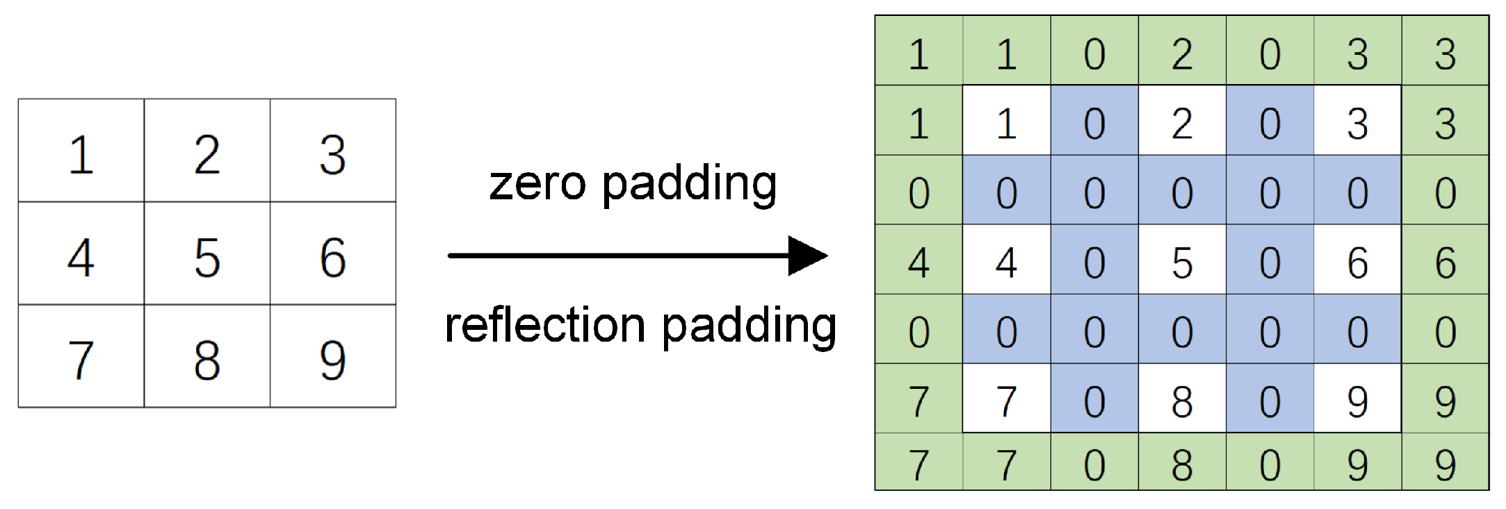
Upsampling is commonly used in image super-resolution processing. To restore the original image size during the decoding, upsampling is also required. Upsampling and convolution are combined in DIC during decoding, and reflection padding is performed to avoid the loss of edge features before convolution. The reflection padding and zero padding are incorporated into the upsampling module, which is convenient for hardware implementation. The process of upsampling is shown in Figure 3. Firstly, zero padding is executed with a step of s k , as the blue part in Figure 3. Then the result after zero padding is reflection padding in the order of (left-right-top-bottom), as shown in the green part.

3. CNN Acceleration Strategy

3.1. Dynamic Hierarchical Quantification

Model compression is essential for mapping complex and heterogeneous CNN models to embedded platforms. Common methods of network compression include pruning [21], sparse matrix [22,23], and quantization [8,10,12]. Model pruning and sparse matrix are not suitable for all networks, such as DIC, because there are no massive zero elements or redundant channels. Fixed-point quantization is an effective way to compress data and help reduce hardware storage and bandwidth workload.
A decimal number n can be expressed in a binary of length L as
n = 2 f l × i = 0 L 1 B i × 2 i
where f l is denoted as the length of the fractional part. Directly converting the 32-bit floating-point numbers trained in DIC to 16-bit fixed-point numbers is coarse-grained quantization, which will cause undesired image distortion. According to the quantization in [8,11], we propose dynamic hierarchical quantization combined coarse- and fine-grained quantization as shown in Figure 4. First, we train the DIC network using 32-bit floating point numbers. Then tensor is collected to obtain information about the network parameters and draw a histogram to show the dynamic range of these parameters. Then the coarse-grained quantization is performed by converting the data and weights into 16-bit fixed points form, respectively, with the overflow data set to the maximum and minimum values. Then fine-grained quantization is performed by converting the parameters to floating-point numbers and importing them into the model for retraining. The trained parameters are fine-tuned so that different layers (i.e., convolutional layers, GDN layers) dynamically adjust the position of the decimal point to meet the accuracy of the operation. Finally, after global adjustment, the 16-bit fixed points data are output.

3.2. Convolution Operations in CNN

The convolution operations are the most computationally intensive component in DIC. Increasing the parallelism of convolutional layer computation can maximize the speed of convolutional computation. However, designing an effective convolutional unit to perform various sizes of convolution at high speed and with compatibility while taking into account hardware platform limitations like storage and multipliers becomes a significant challenge for neural network accelerators [24]. We analyze different schemes of loop optimization and model the function between parallelism and energy efficiency to choose the optimal choice of convolutional parallel strategy.
A convolutional layer can be described by ( M , N , R , C , K , K ) [9] as shown in Figure 5. M and N denote the number of input and output channels. R and C define the number of rows and columns of output feature maps (map). K represents the size of the kernel(or filter) window, which is generally equal in length and width. In addition, the number of rows and columns of the input feature map [25] can be expressed in terms of R i n and C i n . Without considering the padding, ( R i n , C i n ) can be calculated from ( R , C ) and the step size S k .
R i n = ( R 1 ) × S k + K
C i n = ( C 1 ) × S k + K
To obtain the output feature map of layer I, a single convolution required performing multiplication and accumulate(MAC) operations N u m _ s e r i a l _ c o n v ( l ) times. So it is necessary to introduce a loop optimization strategy, where multiple loops perform multiplication and addition in parallel, thus, improving the efficiency of the computation. According to earlier research [9,26,27], the commonly used convolutional loop optimization strategies are mainly classified as loop unrolling, loop tiling, and loop interchange.
N u m _ s e r i a l _ c o n v ( l ) = 2 × M × N × R × C × K × K
# T o t a l _ n u m _ c o n v = l N L N u m _ s e r i a l _ c o n v ( l )
  • Loop unrolling. The loop unrolling design variables are ( U m , U n , U r , U c , U k , U k ) , which represents the number of parallel computations for each layer in the same loop. Loop unrolling is used to do the fully parallel computation for six levels of convolution loops, as shown in Figure 6, which contributes to improving the computational speed of CNN processing. However, some loops are too complicated to unroll under limited hardware resource constraints. On the other hand, it is impossible to unroll all of the loops due to the data reliance between the various loop dimensions.
  • Loop tiling. The data required by the loop are not read one by one when executing the instruction of access for hardware, but a piece of data in a continuous area is stored in a cache line to avoid repeated reading. However, because of the limited size of the cache line, the original data would be lost if fresh data needed to be read but was not previously placed in the cache line. Therefore, it is necessary for loop tiling and storing the data used in convolution into the on-chip buffer to reduce repeated reads. Tiling sizes are represented by variables prefixed with “T”, which are denoted as ( T m , T n , T r , T c , T k , T k ) .
  • Loop interchange. The coarse-grained loop can be promoted outwards to increase parallelism and reduce synchronization overhead. You can also use loop vectorization inward to reduce dependencies between data. Loop interchanges are commutative only if their instances do not depend on each other.
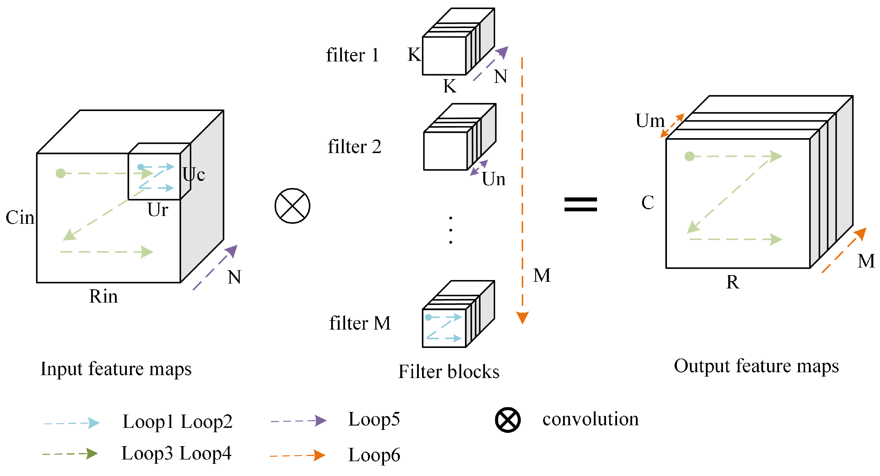
Figure 6. Six levels of convolution loops and loop unrolling.
Electronics 12 02289 g006

3.3. Loop Optimization Modeling

3.3.1. Loop Unrolling Factor

According to previous studies, Loop 1–4 iterations computed early contribute to reducing the storage of partial sums. However, there are three challenges in unrolling K. (1) Since kernel size is generally small that it cannot provide sufficient parallelism. (2) The size of the convolution kernel is different in different layers, so the architecture of convolution may be changed for another layer. (3) To pipeline the computation of the convolution, sampling, and normalization units, it is required to compute the pixels of numerous rows, columns, and the output channels as soon as feasible, which can balance the workload and reduce the waiting cycle of PEs [28]. Therefore, we set the unroll factors ( U r , U c , U m ) to achieve minimum data movements. The cycle required for a complete convolution layer is
c o n v _ c y c l e s = t i l i n g _ o p r e a t i o n s × u n r o l l i n g _ c y c l e s
t i l i n g _ o p r e a t i o n s = M T m N T n R T r C T c K T k K T k
u n r o l l i n g c y c l e s = T m U m T n U n T r U r T c U c T k U k T k U k
The block of data determines the storage size of the on-chip buffer, which in turn affects the read of off-chip storage. In addition, loop unrolling determines the number of multiplication and accumulating units, which in turn affects the DSP resource usage. According to Equations (18) and (19), we need to set ( U r , U c , U m ) be the common factors of R, C, and M as much as possible. Finally, for the DIC network shown in Figure 1.

3.3.2. Loop Tiling Factors

The loop tiling variables affect the accelerator in three main places: (1) the storage size of the on-chip buffer, (2) the DRAM accesses, and (3) the latency of DRAM transactions. Since the data needed to compute one final output feature map are fully buffered, we set T k = K , T n = N , to reduce the partial sum (psums) movement in the PE array. The full rows of the feature map should be cached, i.e., T r = R , to guarantee that DRAM accesses originate from continuous addresses. The hardware platform’s resources must be combined with the determination of T c and T m . We set T c = U c and T m = U m for the Xilinx ZCU104 platform that we used.

4. System Architecture

In this chapter, we give a top-down overview of the design space for the image compression processor. First, the overall architecture of the hardware design is presented to introduce the components of the processor. Then, we will demonstrate each module of our design, including its role and microarchitecture of them. Finally, some implementation details will be added.

4.1. Overall Architecture

Figure 7 shows the overall architecture of the processor described in this paper, which can generate six different bit rates for compressed images after encoding and decoding the input images. The whole system is considered to be composed of PS (Processing System) and PL (Programmable Logic). PS is an ARM-based application processing unit with a large number of integrated memory controllers and peripherals (i.e., I/O interfaces, external memory), which are responsible for providing image data, trained weights, and the corresponding instructions. PS can be completely independent of the programmable logic unit or interconnected to the PL side through the interaction module via the HP and GP interfaces of AXI. PL can be divided into four parts: Storage Buffers, DMAs, Controller, and Operation Module.
  • Storage Buffers include Input Buffer (IB), Output Buffer (OB), and Intermediate Buffer (TB). IB uses a ping-pong structure to store the uncompressed image data and weights, reading, and writing data between the two buffers to increase data reading performance. The encoded or decoded data are stored by OB. The encoded data can either be sent to the operation module through control signals for image decoding operation, or it can be output centrally for decoding by the top computer.
  • DMAs are employed to transport data and instructions between PS and PL to lessen the terminal workload of PS and increase the effectiveness of data transfer. The DMA controller is included internally to import the original image data and weights into different addresses of the input buffer, and the instructions received from the PS are transferred to the Controller after decoding. The enable signal is issued while the IB is filled to start the inference process of the DIC.
  • Controller receives instructions from PS side. On the other hand, it controls the compression inference process according to the state of the operation module. Different from the common image classification application, image compression is divided into the encoding phase and decoding phase. The controller could configure the image to go through convolution, downsampling, and GDN operation during the encoding phase, as shown in Figure 7. The encoded data can be transmitted to the PS directly through the OB as dataflow. Moreover, it can be delivered to the operation module to be decoded, go through IGDN, upsampling, and convolution operation, and finally transmitted to the PS to display the compressed image.
  • The Operation Module is the main part of the image compression processor that is capable of encoding and decoding by adjusting dataflow with the control signal. It contains three pipelined parts: Conv, Sample, and Norm units. Image data and weights are transferred to the Conv unit for convolution first during encoding. The output of the convolution unit would then flow immediately to the downsampling without an idle cycle, which would increase computing efficiency. We design the microarchitecture of the Norm unit with some multipliers and adders that are compatible with IGDN and Batch Normalization (BN).

4.2. Convolution Unit

The pre-encoded image and weights are passed into different regions of the on-chip IB in burst mode via DMA. The three major methods for increasing computational efficiency and conserving data space when executing convolutional operations are parallel operations, data reuse, and reduced psums movement. A PE group (PEG) array is created to accomplish these, as seen in Figure 8. Weights are transferred into the vertical PEG, while the image data are transferred into the horizontal PEG in the form of a broadcast.
The PEG array is based on the traditional PE array, adding one more hierarchy of array depth. P d PEs form a PE group (PEG), and P r × P c PEG form a PEG array. Each PE group has a corresponding local buffer that can store bias. Each PE in the group is responsible for one multiplication and accumulation to compute feature maps of different output channels, and the computed psums can be stored in the local buffer. During the calculation, P r × P c data are passed into the corresponding PE group sharing p d PEs. p d weights are transferred vertically in the array sharing P r × P c PEs. Since the direct unroll of the kernel is not performed, the structure of the adder tree is not needed in the PEG array. The corresponding psums are stored in the local buffer, which can be directly added to the next calculation result. It reduces the movement of partial sums, improves the operation frequency, and increases the storage space of each computational unit. In the implementation, the parameters of the PE group array are reconfigurable, and the structure parameters can be changed according to different networks. Specifically, for the DIC, since the output channels are mostly multiples of 12, the final settings of P r = U r = 9 , P c = U c = 9 , P d = U m = 12 , in combination with the conclusions in Section 3.3.

4.3. Sampling Unit

Downsampling further compresses the features after convolution, and reduces inter-pixel spatial redundancy without multipliers and adders. To be compatible with a generic network model (e.g., VGG-16), we use max-pooling to implement the downsampling process. Since the pooling unit only requires the feature map data from the convolution unit, the output of Conv can be adjusted and passed directly into the max-pooling layer on a per-row basis without additional data access. For a 2 ∗ 2 max-pooling layer, compare each row of data in pairs according to the index with the steps of 2, and the larger value is passed into the buffer for preparation as shown in Figure 9. If the current row is odd (count starts from zero), the odd line needs to be compared again with the data calculated from the previous line, and finally, the largest value is written to the sample output buffer.
The decoding process needs to zero-padding the feature map first to increase the resolution and then convolve it to obtain a larger output feature map. We implement zero-padding by using the sampling unit together with the control module, and adjust the sampling unit to upsampling with the control signal. The inner row is padding with zero first, and the inter-row is padding in the next cycle to achieve the purpose of padding the entire picture. This structure can share a set of storage units with downsample saving hardware overhead.

4.4. Normalization Unit

As seen in Section 3, we implement the GDN layer using a piecewise linear approximation to avoid expensive resource consumption. The sampled pixels are subjected to triple multiplication and one addition operation to acquire the final output data and output it to the Output Buffer. The IGDN is simpler than GDN, requiring only two multiplications and one addition operation, and can reuse the same hardware architecture. As shown in Figure 10, the brown line is the common data line for encoding and decoding, and the purple line is the data line for decoding, which is used in IGDN. To perform the GDN operation, a block of input feature map is cached, multiply γ ^ n plus β ^ n corresponding to the weights of the bars γ ^ n and the bias data point β ^ n . In addition, this architecture can also perform BN by adjusting the control signal Normal Selection, or the input feature data can be output using the comparator to implement ReLu.

5. Experimental Results

5.1. Evaluation of Quantization

Deep learning image compression cannot measure the quality of compression in terms of accuracy directly, unlike using CNN for image classification or target detection, which may analyze errors by checking the accuracy of inference results. Therefore, we need other evaluation indicators to verify the quality of the compressed image. We introduce PSNR and MS-SSIM errors to compare the consequences of dynamic hierarchical quantization.
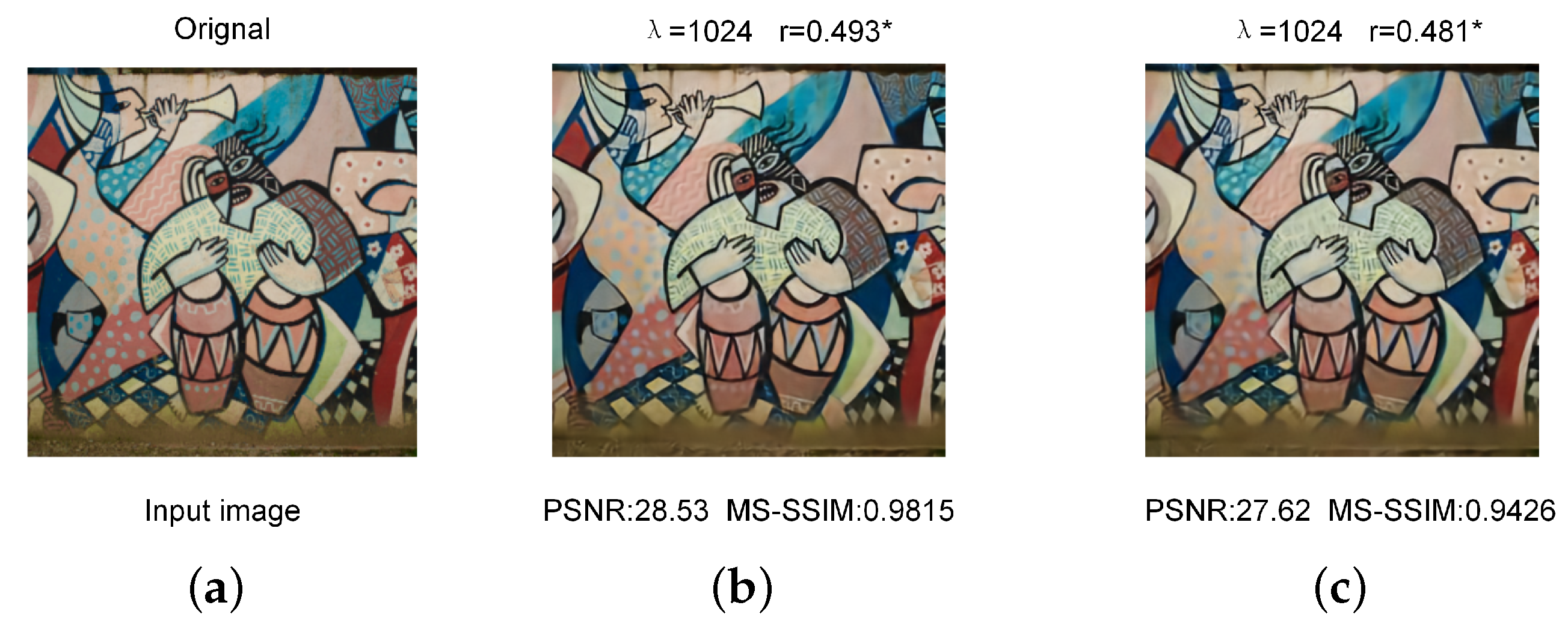
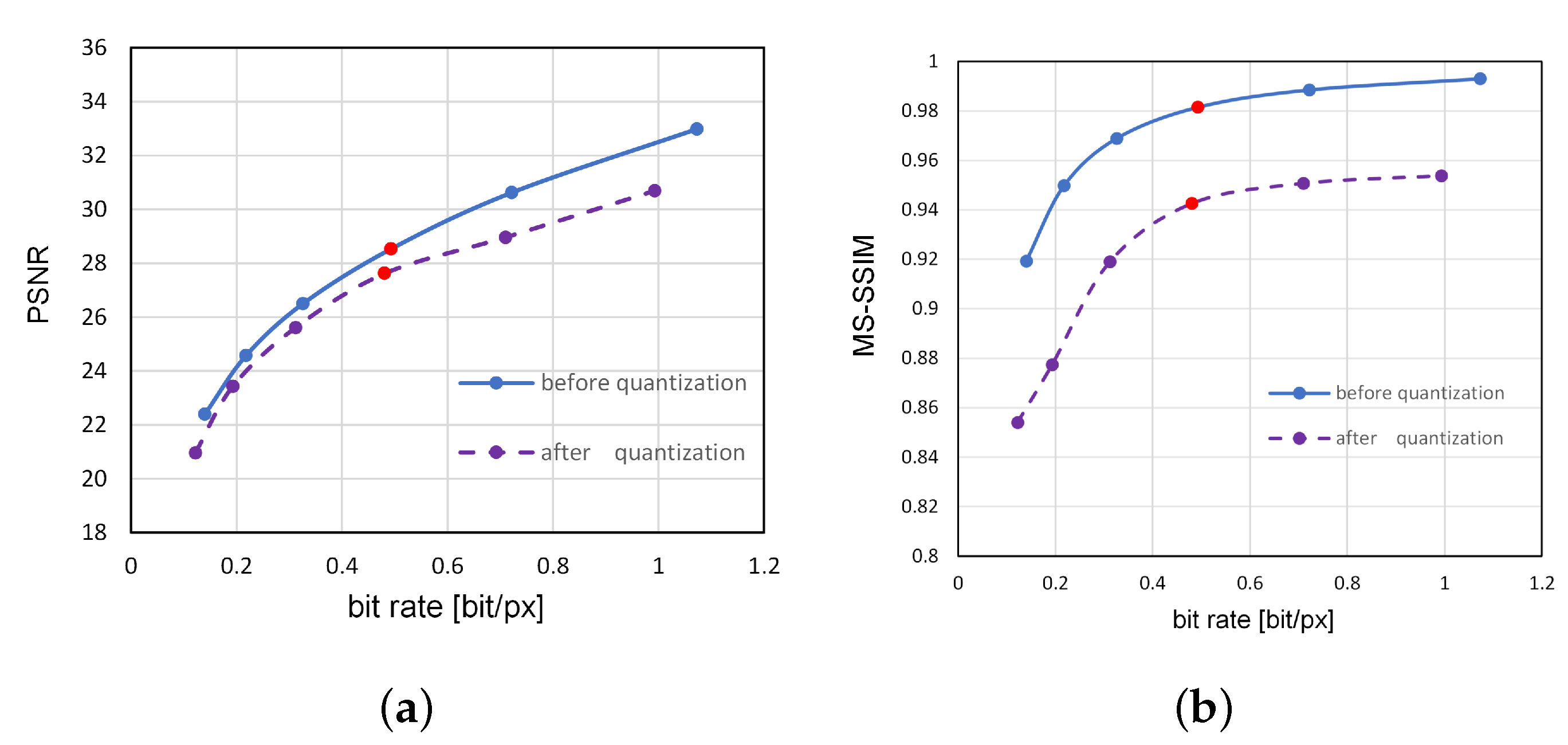
We retrained the DIC network using 6507 images obtained from the Kodak image set and the ImageNet database [29] to obtain the network parameters after dynamic hierarchical quantization. We employ 60 original images in the inference phase, 24 of which come from the Kodak image set. The remaining images are from the ImageNet database, of which 15 images are not included in the training set. Each image can generate six images using DIC at various compression rates depending on λ . We first calculate the reconstructed 360 images and the corresponding PSNR and MS-SSIM values. The model then uses the 16-bit data that have performed dynamic hierarchical quantization to produce 60 sets of images with various compression ratios and corresponding quality metrics. When λ = 2 10 , the evaluation index of the image before and after quantization is shown in Figure 11 and Figure 12. We work out the PSNR error and MS-SSMI error corresponding to each group of images before and after quantization, and the error results are within 7.6% and 5.8%, respectively.

5.2. Hardware Performance

The hardware platform of this experiment is based on the Xilinx Zynq ZCU104, including ARM-Cortex processors, 230K look-up tables (LUT), 461K CKB flip-flops (FF), 1728 digital signal processing (DSP48E). Four 2GB DDR4 DRAMs are used as off-chip storage, equipped with a MicroSD card interface. The development environment is Vivado 2021.2, and the development language is Verilog HDL. After the DIC model is quantized, it is deployed to the FPGA. In addition, to compare the performance of this hardware architecture in different FPGAs, we chose the Zynq ZCU102 as a comparison. Since the hardware architecture has not changed, both development boards use Zynq UltraScale+ MPSoC devices with AMD 16 nm FinFET+ programmable logic architecture. The number of resources used after synthesis and implementation is the same; only the resource utilization differs, as shown in Table 2. It can be seen that the resource utilization on Zynq ZCU102 is lower compared to the Zynq ZCU104.
We tested the Kodak image set, and some other network images, which are divided into more than 60 groups, and each group corresponds to 7 images, including 1 original image and 6 compressed images with different bit rates. We store the parameters of the weights corresponding to the 6 different lambda sets in the off-chip memory. The corresponding weights are transferred to the operator module according to the index without programming the bitstream file into the development board each time.
Since the accelerator for different applications and different models refer to various architectures, we only compare the performance of the convolutional computation modules of the accelerator in a fair way. The throughput rate of the convolutional can be derived as follows by measuring the time of all convolution layers t i m e _ c o n v . This processor, running in Zynq ZCU104 at 200 MHz, compresses a 256 × 256 image taking an average of 15.87 ms for encoding and 14.51 ms for decoding. In comparison with the prior accelerators, the convolutional layer throughput is 283.4 GOPS, which is an obvious improvement, as shown in Table 3. For comparison, the processor on Zynq ZCU102 takes a total of 34.25 ms to compress an image achieving 250.2 GOPS at 200 MHz, due to the difference in resources on board and external structure between the two FPGAs. It can be seen that our proposed processor can efficiently complete the inference process of deep learning image compression with six different compression rates, which may have performance distinctions for different hardware platforms. On the other hand, relative to the current neural network accelerator such as [30,31], the throughput of our processor is improved by 19%, which outperforms previous approaches significantly.
t h r o u g h p u t = # t o t a l _ n u m _ c o n v / t i m e _ c o n v
Earlier neural network accelerator [9] mapped the network model directly into the hardware platform with only loop unrolling and pipelining without quantization, making the DSP efficiency only reach 0.028 GOPS/DSP. A simple data quantization method and a data arrangement method are proposed to ensure high utilization of the external memory bandwidth in [10]. The average performance of convolutional layers is 187.8 GOPS under 150 MHz working frequency in this article. Then, [11] first quantized the weight data with different degrees of 8/10/16/32-bit, using the OpenCL-based scheme to map the VGG-16 into the Altera Stratix-V series boards, which increase in throughput rate from the previous one to 136.5 GOPS. However, such multiple weights with different bit widths make it necessary first to unify the bit widths for multiplication, and additionally, this architecture consumes high energy when performing inference calculations. A unified quantization strategy and compilation tool are proposed in [8] to quantize some specific network weights to 8 bits while the accuracy loss is within 6%, which reduces the power consumption of the hardware. However, this quantization only works better for networks such as VGG, YOLO, etc. [30] explores a faster algorithm using Winograd’s minimal filtering theory for efficient FPGA implementation. This algorithm uses fewer computing resources but puts more pressure on the memory bandwidth. Zhang proposes a reconfigurable CNN accelerator with AXI bus based on ARM + FPGA architecture in [31]. They implemented the proposed architecture on the Xilinx ZCU102 FPGA for YOLOv2. However, it can only reach a throughput of 237.6 GOPS at 300 MHz.
Some articles investigate different hardware architectures to achieve efficient convolutional computation. Systolic arrays have been proposed early for matrix multiplication, and [32] deploys CNN into FPGA with a 2D systolic array. A push-button design flow framework is designed in this article. which raises the frequency to 240 MHz and achieves up to 1TOPS on Intel’s Arria 10 device. To solve the problem of the fast mapping of different networks, [21] created an automated tool called DNNBuilder to develop an optimized parallel mapping method depending on the hardware storage bandwidth and computational resources. However, this approach is not suitable for all network models, and the direct quantization makes the classification network accuracy degrade significantly. When multiple zero operands are present in CNNs, [27] propose a hardware accelerator for sparse CNNs to address the irregular connections in the sparse convolutional layers. At 200 MHz, these final results could achieve 223.4 GOPS on ZCU102. In [33], the YOLO network is mapped directly into the FPGA using a full pipelined approach, which can directly improve the throughput and energy efficiency of the accelerator. However, this scheme requires 3121 DSP support, which is impotent for many FPGA devices.

6. Summary

In this paper, we propose a processor for deep-learning image compression. We first analyze the similarities and differences between deep learning image compression approaches and traditional neural networks. To effectively increase the storage capacity for PE computation while decreasing the part and movement, we propose a PE group array for the convolutional operation in DIC. Each PE group has p d PE computation units accompanied by a local buffer. The sampling unit, in combination with the comparison unit and the filling unit, can efficiently implement the downsampling and upsampling calculations for the codec process. For the GDN and IGDN calculation in the compression process, since it is difficult for the hardware to perform the exponential operations directly, we adopt the piece-wise linear approximation and use a four-stage pipelining to realize the normalization operation step by step. This approach improves computational efficiency and has a fixed latency. Finally, the DIC is implemented on Xilinx ZCU104, which achieves 283.4 GOPS at 200 MHz.

Author Contributions

Conceptualization, H.S. and Z.L.; methodology, B.L., Z.L. and Y.S.; formal analysis, B.L. and H.S.; software, H.S. and Y.S.; investigation, B.L.; data curation, Z.L.; resources, C.Y.; editing, T.W.; supervision, C.Y.; validation, T.W. All authors have read and agreed to the published version of the manuscript.

Funding

This work was supported by the National Key Research and Development Program of China under Grant (2020YFB1406604), National Nature Science Foundation of China (61931008, U21B2024, 62071415), “Pioneer” and “Leading Goose” R&D Program of Zhejiang Province (2022C01068).

Conflicts of Interest

The authors declare no conflict of interest.

References

  1. Jiang, F.; Tao, W.; Liu, S.; Ren, J.; Guo, X.; Zhao, D. An end-to-end compression framework based on convolutional neural networks. IEEE Trans. Circuits Syst. Video Technol. 2017, 28, 3007–3018. [Google Scholar] [CrossRef]
  2. Yasin, H.M.; Abdulazeez, A.M. Image compression based on deep learning: A review. Asian J. Res. Comput. Sci. 2021, 8, 62–76. [Google Scholar] [CrossRef]
  3. Wallace, G.K. The JPEG still picture compression standard. IEEE Trans. Consum. Electron. 1992, 38, xviii–xxxiv. [Google Scholar] [CrossRef]
  4. Liu, Z.; Liu, T.; Wen, W.; Jiang, L.; Xu, J.; Wang, Y.; Quan, G. DeepN-JPEG: A deep neural network favorable JPEG-based image compression framework. In Proceedings of the 55th Annual Design Automation Conference, San Francisco, CA, USA, 24–29 June 2018; pp. 1–6. [Google Scholar]
  5. Li, M.; Zuo, W.; Gu, S.; Zhao, D.; Zhang, D. Learning convolutional networks for content-weighted image compression. In Proceedings of the IEEE conference on computer Vision and Pattern Recognition, Salt Lake City, UT, USA, 18–23 June 2018; pp. 3214–3223. [Google Scholar]
  6. Skodras, A.; Christopoulos, C.; Ebrahimi, T. The JPEG 2000 still image compression standard. IEEE Signal Process. Mag. 2001, 18, 36–58. [Google Scholar] [CrossRef]
  7. Sullivan, G.J.; Ohm, J.R.; Han, W.J.; Wiegand, T. Overview of the high efficiency video coding (HEVC) standard. IEEE Trans. Circuits Syst. Video Technol. 2012, 22, 1649–1668. [Google Scholar] [CrossRef]
  8. Guo, K.; Sui, L.; Qiu, J.; Yu, J.; Wang, J.; Yao, S.; Han, S.; Wang, Y.; Yang, H. Angel-eye: A complete design flow for mapping CNN onto embedded FPGA. IEEE Trans. Comput.-Aided Des. Integr. Circuits Syst. 2017, 37, 35–47. [Google Scholar] [CrossRef]
  9. Zhang, C.; Li, P.; Sun, G.; Guan, Y.; Xiao, B.; Cong, J. Optimizing FPGA-based accelerator design for deep convolutional neural networks. In Proceedings of the 2015 ACM/SIGDA International Symposium on Field-Programmable Gate Arrays, Monterey, CA, USA, 22–24 February 2015; pp. 161–170. [Google Scholar]
  10. Qiu, J.; Wang, J.; Yao, S.; Guo, K.; Li, B.; Zhou, E.; Yu, J.; Tang, T.; Xu, N.; Song, S.; et al. Going deeper with embedded fpga platform for convolutional neural network. In Proceedings of the 2016 ACM/SIGDA International Symposium on Field-Programmable Gate Arrays, Monterey, CA, USA, 21–23 February 2016; pp. 26–35. [Google Scholar]
  11. Suda, N.; Chandra, V.; Dasika, G.; Mohanty, A.; Ma, Y.; Vrudhula, S.; Seo, J.s.; Cao, Y. Throughput-optimized OpenCL-based FPGA accelerator for large-scale convolutional neural networks. In Proceedings of the 2016 ACM/SIGDA International Symposium on Field-Programmable Gate Arrays, Monterey, CA, USA, 21–23 February 2016; pp. 16–25. [Google Scholar]
  12. Chen, Y.H.; Krishna, T.; Emer, J.S.; Sze, V. Eyeriss: An energy-efficient reconfigurable accelerator for deep convolutional neural networks. IEEE J. Solid-State Circuits 2016, 52, 127–138. [Google Scholar] [CrossRef]
  13. Krizhevsky, A.; Sutskever, I.; Hinton, G.E. Imagenet classification with deep convolutional neural networks. Commun. ACM 2017, 60, 84–90. [Google Scholar] [CrossRef]
  14. Dong, C.; Loy, C.C.; He, K.; Tang, X. Learning a deep convolutional network for image super-resolution. In Proceedings of the Computer Vision–ECCV 2014: 13th European Conference, Zurich, Switzerland, 6–12 September 2014; Proceedings, Part IV 13; Springer: Cham, Switzerland, 2014; pp. 184–199. [Google Scholar]
  15. Girshick, R.; Donahue, J.; Darrell, T.; Malik, J. Rich feature hierarchies for accurate object detection and semantic segmentation. In Proceedings of the IEEE Conference on Computer Vision and Pattern Recognition, Columbus, OH, USA, 23–28 June 2014; pp. 580–587. [Google Scholar]
  16. Agustsson, E.; Timofte, R. Ntire 2017 challenge on single image super-resolution: Dataset and study. In Proceedings of the IEEE Conference on Computer Vision and Pattern Recognition Workshops, Honolulu, HI, USA, 21–27 July 2017; pp. 126–135. [Google Scholar]
  17. Lim, B.; Son, S.; Kim, H.; Nah, S.; Mu Lee, K. Enhanced deep residual networks for single image super-resolution. In Proceedings of the IEEE Conference on Computer Vision and Pattern Recognition Workshops, Honolulu, HI, USA, 21–27 July 2017; pp. 136–144. [Google Scholar]
  18. Ballé, J.; Laparra, V.; Simoncelli, E.P. Density modeling of images using a generalized normalization transformation. arXiv 2015, arXiv:1511.06281. [Google Scholar]
  19. Ballé, J.; Minnen, D.; Singh, S.; Hwang, S.J.; Johnston, N. Variational image compression with a scale hyperprior. arXiv 2018, arXiv:1802.01436. [Google Scholar]
  20. Ballé, J.; Laparra, V.; Simoncelli, E.P. End-to-end optimized image compression. arXiv 2016, arXiv:1611.01704. [Google Scholar]
  21. Zhang, X.; Wang, J.; Zhu, C.; Lin, Y.; Xiong, J.; Hwu, W.M.; Chen, D. DNNBuilder: An automated tool for building high-performance DNN hardware accelerators for FPGAs. In Proceedings of the 2018 IEEE/ACM International Conference on Computer-Aided Design (ICCAD), San Diego, CA, USA, 5–8 November 2018; pp. 1–8. [Google Scholar]
  22. Han, S.; Liu, X.; Mao, H.; Pu, J.; Pedram, A.; Horowitz, M.A.; Dally, W.J. EIE: Efficient inference engine on compressed deep neural network. ACM SIGARCH Comput. Archit. News 2016, 44, 243–254. [Google Scholar] [CrossRef]
  23. Gondimalla, A.; Chesnut, N.; Thottethodi, M.; Vijaykumar, T. SparTen: A sparse tensor accelerator for convolutional neural networks. In Proceedings of the 52nd Annual IEEE/ACM International Symposium on Microarchitecture, Columbus, OH, USA, 12–16 October 2019; pp. 151–165. [Google Scholar]
  24. Li, H.; Fan, X.; Jiao, L.; Cao, W.; Zhou, X.; Wang, L. A high performance FPGA-based accelerator for large-scale convolutional neural networks. In Proceedings of the 2016 26th International Conference on Field Programmable Logic and Applications (FPL), Lausanne, Switzerland, 29 October–2 November 2016; pp. 1–9. [Google Scholar]
  25. Ma, Y.; Cao, Y.; Vrudhula, S.; Seo, J.s. Optimizing the convolution operation to accelerate deep neural networks on FPGA. IEEE Trans. Very Large Scale Integr. (VLSI) Syst. 2018, 26, 1354–1367. [Google Scholar] [CrossRef]
  26. Nguyen, D.T.; Nguyen, T.N.; Kim, H.; Lee, H.J. A high-throughput and power-efficient FPGA implementation of YOLO CNN for object detection. IEEE Trans. Very Large Scale Integr. (VLSI) Syst. 2019, 27, 1861–1873. [Google Scholar] [CrossRef]
  27. Lu, L.; Xie, J.; Huang, R.; Zhang, J.; Lin, W.; Liang, Y. An efficient hardware accelerator for sparse convolutional neural networks on FPGAs. In Proceedings of the 2019 IEEE 27th Annual International Symposium on Field-Programmable Custom Computing Machines (FCCM), San Diego, CA, USA, 28 April–1 May 2019; pp. 17–25. [Google Scholar]
  28. Ma, Y.; Cao, Y.; Vrudhula, S.; Seo, J.S. Performance modeling for CNN inference accelerators on FPGA. IEEE Trans. Comput.-Aided Des. Integr. Circuits Syst. 2019, 39, 843–856. [Google Scholar] [CrossRef]
  29. Deng, J.; Dong, W.; Socher, R.; Li, L.J.; Li, K.; Fei-Fei, L. Imagenet: A large-scale hierarchical image database. In Proceedings of the 2009 IEEE Conference on Computer Vision and Pattern Recognition, Miami, FL, USA, 20–25 June 2009; pp. 248–255. [Google Scholar]
  30. Xiao, Q.; Liang, Y.; Lu, L.; Yan, S.; Tai, Y.W. Exploring heterogeneous algorithms for accelerating deep convolutional neural networks on FPGAs. In Proceedings of the 54th Annual Design Automation Conference 2017, Austin, TX, USA, 18–22 June 2017; pp. 1–6. [Google Scholar]
  31. Zhang, S.; Cao, J.; Zhang, Q.; Zhang, Q.; Zhang, Y.; Wang, Y. An fpga-based reconfigurable cnn accelerator for yolo. In Proceedings of the 2020 IEEE 3rd International Conference on Electronics Technology (ICET), Chengdu, China, 8–11 May 2020; pp. 74–78. [Google Scholar]
  32. Wei, X.; Yu, C.H.; Zhang, P.; Chen, Y.; Wang, Y.; Hu, H.; Liang, Y.; Cong, J. Automated systolic array architecture synthesis for high throughput CNN inference on FPGAs. In Proceedings of the 54th Annual Design Automation Conference 2017, Austin, TX, USA, 18–22 June 2017; pp. 1–6. [Google Scholar]
  33. Huang, W.; Wu, H.; Chen, Q.; Luo, C.; Zeng, S.; Li, T.; Huang, Y. FPGA-based high-throughput CNN hardware accelerator with high computing resource utilization ratio. IEEE Trans. Neural Netw. Learn. Syst. 2021, 33, 4069–4083. [Google Scholar] [CrossRef] [PubMed]
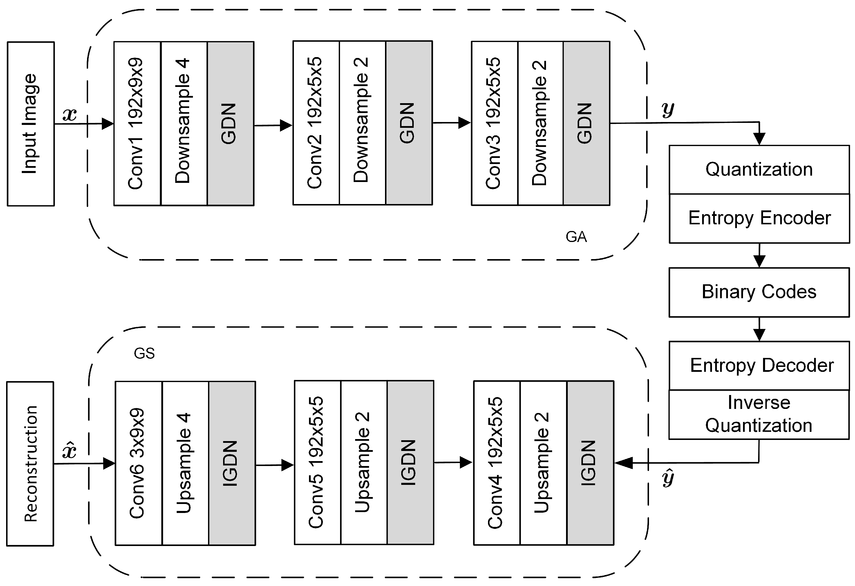
Figure 1. Architecture of DIC. A vector of image intensities x is converted to a latent code space y via analysis transform (GA). y is then quantized, entropy encoded, and inverse transmitted to obtain y ^ . The decoder then feeds y ^ into synthesis transforms (GS) to obtain the reconstructed image x ^ .
Electronics 12 02289 g001
Figure 2. Piecewise linear function. (a) Approximate function for Equation (3); (b) approximate function for Equation (9).
Electronics 12 02289 g002
Figure 3. Upsampling with zero and reflection padding.
Electronics 12 02289 g003
Figure 4. Dynamic hierarchical quantification.
Electronics 12 02289 g004
Figure 5. Six levels of convolution loops, where l c denotes the index of convolution layer.
Electronics 12 02289 g005
Figure 7. The overview of the proposed image compression processor architecture.
Electronics 12 02289 g007
Figure 8. The microarchitecture of the conv unit.
Electronics 12 02289 g008
Figure 9. The microarchitecture of the sampling unit.
Electronics 12 02289 g009
Figure 10. The microarchitecture of Norm unit.
Electronics 12 02289 g010
Figure 11. Evaluation of quantization. (a) The original image; (b) the reconstructed image before quantization; (c) the reconstructed image after quantization; * bit rate (bit/pixel).
Electronics 12 02289 g011
Figure 12. Rate–distortion curves for the luma component of the image. (a) Peak signal-to-noise ratio; (b) measured with multi-scale structural similarity (MS-SSIM). The red dots indicate the bit rates and evaluation metrics corresponding to when λ = 2 10 as shown in Figure 11.
Electronics 12 02289 g012
Table 1. Operations in DIC model.
LayerChannelFm Size (R = C)Kernel Size (K)Stride#Operations
Original
image
3256——————
Conv11927794553,246,848
Conv219237522,523,340,800
Conv31921752532,684,800
Conv419237522,523,340,800
Conv51927752553,246,848
Conv63256941,887,436,800
#Operations indicates the number of sums and products in each layer.
Table 2. Resource utilization of the processor.
ResourceFFLUTDSP48BRAM
(18 Kb)
Utilization197,843214,7051042549
Percent (Zynq ZCU102)36.0278.3341.2730.1
Percent (Zynq ZCU104)42.9393.1960.387.98
Table 3. Performance comparison with previous works.
Work [8] [10] [30] [31]This Work
ModelVGG16VGG16VGG16YOLOV2DICDIC
PlatformXC7Z020XC7Z020XC7Z045ZCU102ZCU102ZCU104
Clock (MHz)214150100300200200
Precision8-bit fixed16-bit fixed8-bit fixed16-bit fixed16-bit fixed16-bit fixed
CNN size (GOP)30.7630.7630.765.48.578.57
Power (W)3.59.639.411.813.713.2
DSP used78078082460910421042
Throughput  a 84.3187.8239237.6250.2283.4
Efficiency  b 24.119.5024.4220.1318.2621.47
DSP Efficiency  c 0.1080.2410.2900.3900.2400.272
a: Giga Operations Per Second(GOPS); b: Throughput/power(GOPS/W); c: Throughput/DSP(GOPS/DSP).
Disclaimer/Publisher’s Note: The statements, opinions and data contained in all publications are solely those of the individual author(s) and contributor(s) and not of MDPI and/or the editor(s). MDPI and/or the editor(s) disclaim responsibility for any injury to people or property resulting from any ideas, methods, instructions or products referred to in the content.