Abstract
Overtaking is a maneuver that consists of passing another vehicle traveling on the same trajectory, but at a slower speed. Overtaking is considered one of the most dangerous, delicate and complex maneuvers performed by a vehicle, as it requires a quick assessment of the distance and speed of the vehicle to be overtaken, and also the estimation of the available space for the maneuver. In particular, most drivers have difficulty overtaking a vehicle in the presence of vehicles coming on other trajectories. To solve these overtaking problems, this article proposes a method of performing safe, autonomous-vehicle maneuvers through the PreScan simulation program. In this environment, the overtaking-maneuver scenario (OMS) is composed of highway infrastructure, vehicles and sensors. The proposed OMS is based on the solution of minimizing the risks of collision in the presence of any oncoming vehicle during the overtaking maneuver. It is proven that the overtaking maneuver of an autonomous vehicle is safe to perform through the use of advanced driver-assistance systems (ADAS) such as adaptive cruise control (ACC) and technology-independent sensors (TIS) that detect the driving environment of the maneuver.
1. Introduction
Over time, the process of integrating automation systems into commercial vehicles is becoming more and more evident. Among the triggers for this integration are, in particular, traffic accidents, and specifically, collisions, which are mostly related to human mistakes when performing high-risk maneuvers, such as overtaking and obstacle avoidance. Basically, overtaking is passing another vehicle traveling on the same trajectory at a lower speed [1]. To avoid a collision, the driver performing the maneuver calculates the time remaining before colliding with the vehicle approaching from the opposite direction. Performing these calculations in real time is difficult, because it means that the human driver must take into account situations such as traffic or the speed of other vehicles [2].
Therefore, different manufacturers and research groups around the world are working on the development of systems to improve driving in urban areas and highways [3]. Autonomous vehicles (AVs) are part of this development, due to their role as an intelligent transportation system (ITS), in which control and communication techniques such as advanced driver-assistance systems (ADAS) are applied [4]. The research into cooperative maneuvers such as overtaking between AVs is one of the most challenging areas in the field of ITS and ADAS systems, since overtaking is a high-risk maneuver. Decisions made in the execution of overtaking maneuvers depend not only on the state of the vehicle, but also on many other variables, such as environmental factors, surrounding conditions, the distance of the vehicle to curves and intersections, the position and speed of other vehicles, etc.
The ADAS systems also provide control systems such as adaptive cruise control (ACC); this system allows the vehicle to drive in an autonomous mode once a cruising speed and a safety distance have been set. Thanks to this device, the vehicle accelerates and brakes in accordance with the traffic conditions present, and the driver has the opportunity to relax in the driver’s seat while keeping the situation under control [5,6].
Several studies have suggested applications associated with ADAS systems to perform an overtaking maneuver. Similarly, many studies have explored the use of control systems such as model predictive control (MPC), algorithms, and sensors such as cameras, the Global Positioning System (GPS) and RADAR, to perform an autonomous overtaking maneuver.
However, no study has focused solely on the performance of overtaking maneuvers with ADAS systems such as ACC and technology-independent sensors (TIS), whose operations are a combination of RADAR and LIDAR.
In this study, in order to provide parity between the different elements that constitute the overtaking situation, an overtaking-maneuver scenario (OMS) with optimal trajectory generation for autonomous vehicle overtaking without collisions, was developed. This OMS is proposed for a three-lane highway, in which several elements, such as the highway infrastructure, sensors, and vehicles are combined. PreScan was used to build and recreate the OMS simulation features for the overtaking maneuver.
This study explores how an autonomous vehicle overtakes another vehicle traveling io the same trajectory at a lower speed. This includes comprehending what elements are involved and how sensors, highway infrastructure, vehicles or their combination contribute to the successful performance of the overtaking maneuver. Furthermore, it implies understanding in the near future how the ADAS system will adapt to real-life interaction with AVs.
This article is structured as follows. Section 2 discusses the overtaking maneuver and the different control methods to improve active safety. Section 3 describes the OMS. Section 4 presents the OMS results. Section 5, together with the limitations of the study, discusses and analyses the results obtained. Finally, the last section presents the conclusions of the study.
2. Literature Review
Driving systems have become more complex with time, leading to the development of new technologies in order to improve driving performance and stability [7]. This is also the case with AVs, which provide numerous benefits to people who, for some reason, cannot or should not drive. Such a solution could lead to improved access to education, employment opportunities, and increased productivity, by reducing the burden on the families and friends of people who cannot drive [8,9].
The AVs also have numerous advantages, such as reducing traffic congestion, reducing fuel consumption, improving public transportation services, and facilitating maneuvers [10]. The application of new technologies in maneuvers implies that interactions between AVs and environmental sensing may improve safety, efficiency and sustainability [11,12].
One of the most challenging maneuvers is overtaking, because the maneuver does not depend only on the state of the vehicle but also on many other variables, such as environmental conditions, the distance of the vehicle to curves or intersections, the type of highway, the traffic signals, and the position and speed of other vehicles. Overtaking, considered a common practice between vehicles, involves the consideration of a series of factors by the users. These factors include the dimensions of the highway, the speed of both the vehicle performing the maneuver and the vehicle to be overtaken, and also the applicable traffic laws and regulations. [13].
Regarding autonomous overtaking, the main issue is to determine the onboard system carried by the AVs. The onboard system determines how decision making is planned during the operation of the AVs on the highway. The systems are also responsible for providing safety in various scenarios. To achieve successful overtaking, the vehicle with the onboard system must calculate parameters such as speed, distance and time [14].
One of the most popular onboard systems used in AVs is the adaptive cruise control (ACC). The ACC system bases its operation on sensors and RADARs, which are used to control the speed and position of the AVs automatically. A notable feature of ACC systems is the possibility of detecting and analyzing avoidable collisions with other vehicles in a specific environment [15]. The emergency brake is activated if the system detects that the collision is inevitable even with evasive maneuvers [16].
Yi et al. [17] proposed a control scheme that uses a full-range ACC with braking, for a collision-avoidance system. The algorithm can perform user-like driving in high and low-speed gears. Moon et al. [18] also used an algorithm comprised of full-range ACC for collision avoidance. With this algorithm, the vehicle in question operates in three modes: (1) comfort, (2) high, and (3) severe braking.
Another method for improving overtaking maneuvers is the model predictive control (MPC). MPC is a control algorithm that calculates in real time a sequence of future actions of a system, in order to provide a basis for optimizing future control actions [19,20]. Wang et al. [21] used the MPC as a method for autonomous navigation of unmanned surface vessels (USVs). MPC creates commands for precise tracking control of the USVs, to avoid collisions with objects detected around. The study carried out by Wang et al. [22] proposed a method to minimize the risk of collisions between a group of vehicles. This method uses an MPC controller and a coordinated brake control (CBC) that further helps the vehicle to reduce the impact when a collision with another vehicle is unavoidable. Lin et al. [23] presented a collision-avoidance system that predicts the obstacle trajectory using a trajectory-replanning controller integrated with driver characteristics, longitudinal control and vehicle speed. Wnag et al. [24] studied a new method that consists of the development of a trajectory-tracking controller and a path planner to avoid collisions of autonomous vehicles, based on active front-steering systems (AFS). The MPC can also be used as a 3D tracking-control tool. This is done through a symplectic pseudospectral optimal-control method that performs tracking of the reference trajectory [25].
Bae and Lee [26] suggested an adaptive overtaking-assistance system (VAOAS) based on vehiclar ad hoc networks (VANET). The VAOAS system calculates the safe passing distance and the passing sight-distance, based on other vehicles’ location and speed, and provides either a warning or an overtaking-approval message. Mei et al. [27] presented a robust motion-detection and planning method for avoiding vehicles parked on the roadside. The method uses lidar and long-range radar sensors in a complementary manner for obstacle detection. Zhu et al. et al. [28] developed a system that uses a fusion algorithm and dynamic scenes to detect overtaking vehicles. Their modelling technique for the identification of overtaking vehicles combines dynamic-scene modeling, hypothesis testing, multi-scale means-displacement-based information fusion, and bandwidth density. The combination of these techniques results in a reliable model for detecting overtaking vehicles [29].
A novel technique for performing overtaking maneuvers is through a heuristic algorithm. With this algorithm, the AVs are able to determine an optimal distance and speed based on the relative position of other vehicles involved in the overtaking maneuver [14].
Yang et al. [30] designed and validated a decision-making system to generate overtaking decisions by using a deep neural network (DNN). With this system, the DNN can learn the decisions of humans in complex situations, and implement them in the AVs. An automatic overtaking-maneuver can be performed through vision sensors (cameras, GPS or a global navigation satellite system (GNSS) and the inertial measurement unit), and longitudinal and lateral control- systems based on fuzzy controllers [31,32]. The study by Anindyaguna et al. [33] also proposed using a fuzzy controller, but with the difference that it used a camera combined with two components: GPS and radio control (RC).
Petrov et al. [34] proposed a nonlinear adaptive controller using third-order reference trajectories for automated two-vehicle overtaking maneuvers. The trajectories and the derived kinematic relationships between the vehicles were used to establish a rationale for designing a feedback control based on kinematics. Andersen et al. [35] developed a method to perform overtaking by generating a trajectory planner. With this method, the planner is guided by a real-time non-linear system that captures trajectory information, so that AVs can overtake safely.
A modern approach to vehicle identification during an overtaking maneuver is through the use of a Kinect system. Through red, green and blue, plus depth (RGB-D) data collected within traffic scenes, the action of the detected vehicle is identified and tracked at the moment of the overtaking maneuver [36].
Olaverri-Monreal et al. [37] proposed the see-through system (STS). With STS, AVs can have a perspective view of another vehicle. To obtain an even clearer view, video transmission technology and VANET are used to stream video between the involved vehicles in the overtaking maneuver.
The scientific literature on AVs and the different systems for improving driving performance and stability shows a gap in the development of scenarios involving overtaking maneuvers with AVs. This article aims to develop an OMS through a simulation program of a safe overtaking-maneuver that combines highway infrastructure, vehicles and systems and technology-independent sensors (TIS).
3. Modeling Approach
This section presents in detail the simulation conditions to be fulfilled in an overtaking-maneuver scenario (OMS) with autonomous vehicles. Subsequently, a description of the construction of the OMS is included. Finally, the auxiliary settings implemented with MATLAB/SIMULINK software are explained, in order to establish the simulation parameters of the OMS.
Figure 1 shows the flowchart of our study. This flowchart illustrates the procedure that the OMS follows to carry out an overtaking maneuver.
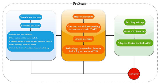
Figure 1.
The flowchart of the method developed for the overtaking maneuver in PreScan.
3.1. Simulation Features
The first step in the scenario-building process is to specify the conditions of the simulation. Next, the conditions necessary for the OMS simulation with autonomous vehicles are specified:
- The OMS has three lanes of highway;
- There are three vehicles, named A, B, and C;
- The speed reached by vehicle A is faster than that of vehicle C;
- In the left lane (1), vehicle B is located;
- Vehicle C and vehicle A must be in the same lane of the highway.
Once the simulation conditions are known, a virtual experiment can be constructed, using the PreScan simulation function, in which different simulation elements such as the highway infrastructure, vehicles, and sensors are combined. The following subsections explain in detail how an OMS is constructed and which control systems are used to carry out the simulation.
3.1.1. Stage Construction
The first step in the construction of the OMS is to determine the number of lanes of the highway. In this OMS, a three-lane highway was chosen, with lanes designated as the left lane (1), the center lane (2) and the right lane (3) (see Figure 2).
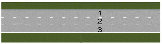
Figure 2.
Scheme and layout of OMS highway infrastructure in PreScan.
This type of layout was chosen because in this type of lane, vehicles travelling in both directions can use the center lane for passing, and thus approaching traffic may intend to make the same maneuver at the same time.
In lane 2 there are two vehicles: vehicle A, which is responsible for carrying out the overtaking maneuver, and vehicle C, which is ahead of vehicle A. Since both vehicles (A and C) are located in lane 2, both vehicles move io the same trajectory, which goes from X to Z (see Figure 3).
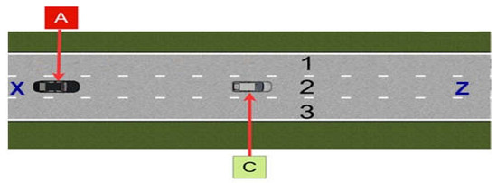
Figure 3.
OMS with vehicles located in the center lane (2).
In lane 1, there is one vehicle, vehicle B, which has a trajectory that goes from Z to X. As shown in Figure 4, the trajectory of vehicle B going from Z to X is the opposite of that of vehicles A and C, which goes from X to Z: i.e., the trajectory in lane 1 is different from the trajectory in lane 2.
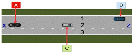
Figure 4.
OMS with vehicles located in the left lane (1) and in the center lane (2).
Once the highway infrastructure and the vehicles (A, C, B) that interact with the OMS have been determined, it is possible to determine the sensors that operate with the autonomous vehicle in the OMS.
Vehicle A, being responsible for performing the overtaking maneuver, is equipped with two technology-independent sensors (TIS), and each of these sensors is labeled with a color in order to identify it in the OMS. The first TIS sensor is labeled yellow (TIS1), while the other TIS sensor is labeled red (TIS2) (see Figure 5).
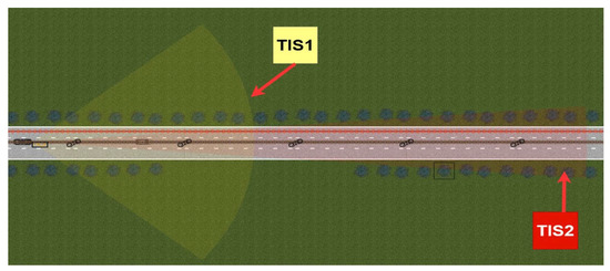
Figure 5.
Short-range sensor (TS1) and long-range sensor (TS2) in vehicle A.
The operation of the TIS sensor is based on the combination of the technology of two sensors: RADAR and LIDAR. This allows the sensor to have a general active scanning and not be limited to a specific technology (such as radar, lidar or laser scanner).
TIS sensors can help to use and understand other sensors for active scanning, as they have a strong scene-scanning performance. This allows them to receive information about the environment and the obstacles.
As vehicle A moves along the highway path, it tracks and detects the vehicles that are in the OMS. The range distance assigned for short-range detection is given by TS1, which has a range of 60 m. For long-range detection, the TS2 is designated. This sensor has a range of 150 m.
3.1.2. Auxiliary Settings
After building the OMS with all the necessary elements (highway infrastructure, vehicles and sensors), it is necessary to execute auxiliary adjustments; i.e., using a graphical programming software such as MATLAB/Simulink, an analysis of the OMS is carried out through a graphical user interface (GUI). This is achieved through the interactive use of the block-diagram systems that make up the OMS (see Figure 6).In addition, through the GUI it is possible to add ADAS, such as ACC.
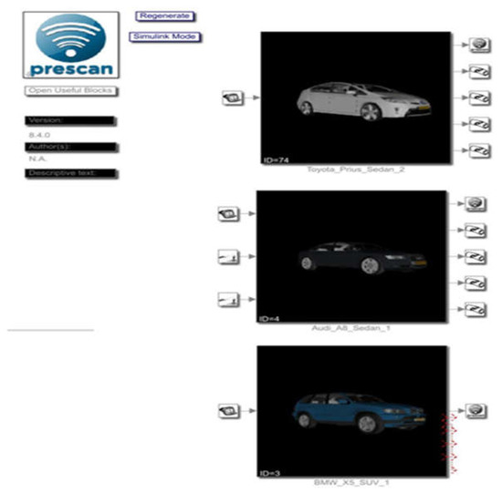
Figure 6.
Compilation sheet in MATBLAB/Simulink.
With ACC technology, vehicle A may be able to modify its speed, depending on whether there are vehicles ahead traveling at a lower speed. In the case of failure, the user can also enter new values for the identified problem areas.
If the OMS contains all the road infrastructure, vehicles and sensors needed for the simulation, a compilation sheet is created, which allows for the launching of the experiment. Figure 7 Shows a 3D scene during simulation, through a PreScan window called VisViewer.
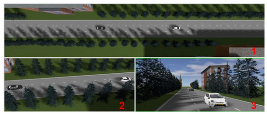
Figure 7.
Viewpoints on PreScan.
Through VisViewer, the OMS scene can be handled from three types of viewpoints, such as: (1) the default viewpoints, (2) the PreScan libraries viewpoints, and (3) the VisViewer viewpoint (see Figure 7). Each of these viewpoints provides a view of the overtaking maneuver, which results in a better visualization of the OMS analysis.
PreScan provides a preprocessing system for defining the OMS, and an execution environment to carry it out. An accurate and complete simulation was performed to achieve an OMS that fulfills all the guidelines established by the simulation conditions. Furthermore, an analysis was performed through the GUI to optimize the OMS simulation.
4. Results
The results set out in this section consist of three phases. Each of these phases includes a description of the elements that compose the OMS (see Figure 8).
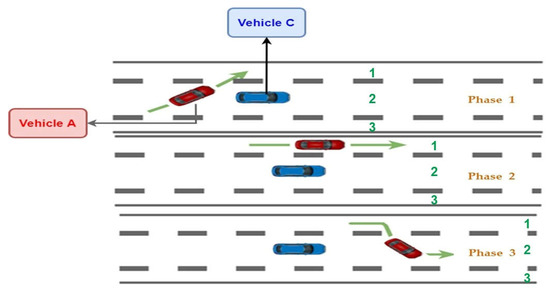
Figure 8.
Scheme of overtaking-maneuver phases.
Phase 1 shows the behavior of vehicle A upon starting to carry out the overtaking maneuver. In addition, during Phase 1, vehicle A is analyzed when detecting other vehicles (B and C) through the TIS sensors and the ACC controller.
Phase 2 shows the change of lane made by vehicle A at the end of Phase 1. In this change of lane, which is from lane 2 to lane 1, vehicle A moves until it manages to pass vehicle C. As a result, Phase 2 ends and Phase 3 begins.
Finally, Phase 3 describes how vehicle A returns to its original lane, which is lane 2. This results in the end of the overtaking maneuver.
4.1. Phase 1
In Phase 1, vehicle A, which is located in lane 2, starts moving along its trajectory from X to Z at an initial speed of 54 km/h (see Figure 9). As vehicle A moves along its trajectory, (X–Z), its speed progressively increases until it eventually encounters another vehicle ahead, which would cause it to slow down.
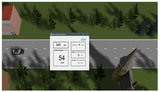
Figure 9.
Ego-vehicle parameters showing lower speed of the vehicle A.
In phase 1, both the TIS sensors and the ACC controller in vehicle A continuously monitor the OMS.
Figure 10 shows two TIS sensors in vehicle A. Each of the TIS sensors is labeled with a color: the first TIS sensor is labeled red, and has a range of 60 m; d the other TIS sensor is labeled blue, and has a range of 150 m.
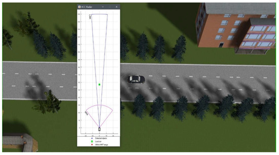
Figure 10.
Vehicle A with TIS sensors in PreScan.
Vehicle C is represented by a green dot when it is detected by the TIS sensors in vehicle A.
Once the vehicles have been identified through the TIS sensors, a signal is sent to the ACC controller, which enters demanded-headway-time (HWT) mode (see Figure 11), i.e., vehicle A brakes and starts to reduce its speed, and thus avoids a collision with vehicle C.
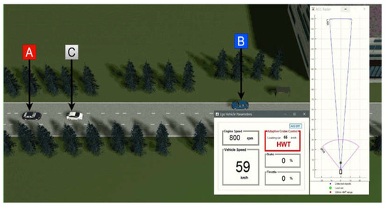
Figure 11.
Vehicle A with TIS sensors and ACC controller.
4.2. Phase 2
Regarding the ACC controller and TIS sensors, as mentioned before, they also start to work when vehicle A starts to move along its trajectory (X–Z). Figure 12 shows how vehicle A starts to reduce its speed from 59 km/h to 58 km/h when it approaches vehicle C. This speed reduction is made possible by the TIS sensors on vehicle A, which detect the vehicles ahead (B and C) and thus provide an overview of the OMS environment.
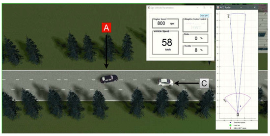
Figure 12.
Vehicle A moving from lane 2 to lane 1.
In Phase 2, vehicle A is behind vehicle C, while vehicle B continues to move along its path (Z–X) (see Figure 4). In Phase 2, vehicle A still continues detecting both vehicles C and B through the TIS sensors and ACC control.
As shown in Figure 12, vehicle A starts to change lane (from lane 2 to lane 1), and thus begins the overtaking maneuver. This change of lane happens only when vehicle A, through the TIS sensors and the ACC controller, detects that there is no danger of collision with vehicle C, and vehicle B is already ahead of vehicle C and A.
Vehicle A, once in lane 1, is still following the same trajectory (X–Z). In Phase 2, vehicle A, which is moving in lane 1, starts to accelerate, which causes the speed increase until it overtakes vehicle C. As shown in Figure 13, vehicle A increases to a speed of 98 km/h in order to overtake vehicle C. Throughout the lane change, both the TIS sensors and the ACC controller keep working continuously to detect and act, in case there are vehicles ahead of vehicle A.
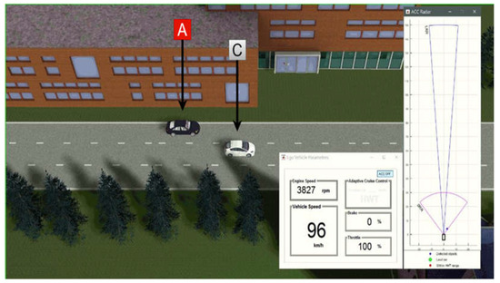
Figure 13.
Second phase of the overtaking maneuver.
In Phase 2, when vehicle A detects that there are no vehicles ahead, it again sends a signal to the ACC controller, which causes the HWT mode to be deactivated.
4.3. Phase 3
Finally, in Phase 3, vehicle A, once it has overtaken vehicle C, can return to its original lane 2 (see Figure 14) to complete the overtaking maneuver. At the end of the overtaking maneuver, vehicle A can start accelerating, causing the speed to increase to 119 km/h, until it progressively moves away from vehicle C (see Figure 15).
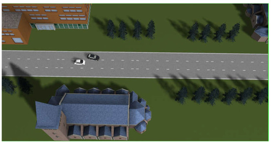
Figure 14.
Vehicle A changing phase, from left lane to center lane.
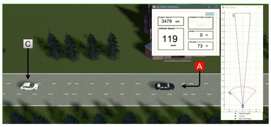
Figure 15.
Third phase of the overtaking maneuver.
5. Discussion
Single-lane highway overtaking is a common OMS that is present on most highways, and hence most studies that have been conducted on overtaking with autonomous vehicles opt for this type of OMS. However, when dealing with an OMS with three lanes of highway and with vehicles that have a different trajectory than the vehicle performing the overtaking maneuver, the operation of typical overtaking on a single-lane highway is not guaranteed. To solve this problem, in this article an analysis of the overtaking maneuver with autonomous vehicles on a three-lane highway is presented, with a vehicle on a trajectory opposite to that of the vehicle performing the overtaking maneuver.
The results obtained demonstrate that the PreScan software is a versatile tool, which is able to build scenarios with highway infrastructure, AVs and ADAS systems. This allows obtaining data close to reality without the need to use real vehicles or physical infrastructure. The OMS simulation showed how vehicle A starts to slow down gradually when it approaches vehicle C. This speed change is due to the assistance of the ACC system. The results also showed that with the help of TIS sensors, vehicle A can continuously monitor its area to avoid a collision with both vehicle C and vehicle B.
From the results obtained in the OMS, for an autonomous vehicle to perform an overtaking maneuver of another vehicle that is in the same lane of the highway moving at a lower speed, and at the same time having to deal with vehicles that are in an opposite lane to the vehicle performing the maneuver, it is necessary that all the analyzed phases (1, 2, 3) fulfill the conditions of the simulation, in order for sensors such as TIS and the ACC controller to detect the driving environment. Under these conditions, an autonomous vehicle can perform the overtaking maneuver.
Figure 9 shows vehicle A with an initial speed of 54 km/h increasing its speed to a maximum speed of 59 km/h (see Figure 11) to catch up with vehicle C. Once vehicle A catches up with vehicle C, it starts the overtaking maneuver. The speed of vehicle A is progressively reduced, while vehicle C maintains a speed of 58 km/h, as shown in Figure 12. Vehicle A performs the lane-change maneuver (lane 2 to lane 1). To perform this lane-change maneuver, vehicle A increases its speed to 96 km/h (see Figure 13). When vehicle A achieves the overtaking maneuver with respect to vehicle C, vehicle A returns to lane 2, and once the overtaking maneuver has been performed, vehicle A increases its speed to 119 km/h, to move away from vehicle C. This can be compared to an overtaking maneuver performed in the literature by Né-meth et al. [38], who designed a scenario with three lanes and with the overtaking maneuver in lane 2. The overtaking scenario proposed by the author starts with vehicle A, whose initial speed is 110 km/h, which is reduced once it reaches vehicle C, and maintains similar speeds of 90 km/h, subsequently increasing to a speed higher than that of vehicle C, to perform the overtaking maneuver. This means that in our research, as in Nemeth’s, in order to perform the overtaking maneuver, it is necessary that the vehicle that performs the overtaking maneuver (vehicle A) performs speed changes (acceleration and deceleration), and these speed differences depend on the speed of the vehicle to be overtaken, which is vehicle C.
The limitations of this study are that the speed and lateral movement of vehicles B and C are constant in the scenario simulation, thereby not generating speed changes. In addition, the scenario constructed in this work only considers the use of three vehicles on a three-lane highway, and does not cover the inclusion of other elements such as traffic signs, pedestrians or more vehicles. These topics could offer a fascinating continuation of this work.
6. Conclusions
An autonomous vehicle is a vehicle with a complex system, in which many technologies and different disciplines such as artificial vision, mechanics, and even geopositioning, are involved. AVs convert and expand the present circumstances through small and subtle details entirely into the future, and modify various aspects already known in vehicles, to achieve better safety or comfort. This article aims to present a method of performing safe maneuvers with AVs through the PreScan simulation program, in which the OMS is composed of highway infrastructure, vehicles and sensors.
The study presented in this article is governed by modeling approaches such as stage construction and auxiliary settings. Each of these models employs a program for the development of the scenario. For scenario construction, a simulation program is used, in order to create highway infrastructure. For auxiliary settings, a graphical programming program (MATLAB/Simulink) was applied, to modify and interpret a graphical user interface (GUI). Moreover, each methodology is governed by simulation conditions that must be fulfilled in order to perform the overtaking maneuver with AVs.
The proposed OMS can incorporate a safe overtaking driving-system in the front of vehicles that have an opposite trajectory to the vehicle that carries out the maneuver. The proposed OMS can be employed as a fully automated system, using ADAS systems such as the ACC controller and TIS sensors, to detect the driving environment for performing the overtaking maneuver.
The OMS complies with EuroNCAP tests. These tests mention that the autonomous vehicle-assistance evaluations consist of an ACC system that has a lateral assistance to control the position of the vehicle when moving in a fully marked lane and at a desired test speed.
An autonomous vehicle that has an ACC controller and TIS sensors can perform an overtaking maneuver while controlling its speed and recognizing vehicles on the same trajectory or on the opposite trajectory.
Considering further research, it is proposed that the scenario used here should be complemented with different elements on the highway, such as traffic signs, traffic signals, pedestrians, or more vehicles, to study the behavior of the maneuver when interacting with more elements. Another interesting extension could be the implementation of several sensors in more vehicles and for the highway infrastructure to have a continuous data network that can assist the autonomous vehicle to perform and carry out different actions based on the information from the environment. In addition, adding other ADAS systems that help to analyze the behavior of the vehicle which has systems that help to perform different maneuvers.
Author Contributions
Conceptualization, J.O. (Jairo Ortega); Methodology, J.O. (Josue Ortega); Formal analysis, J.O. (Josue Ortega) and H.L.; Investigation, H.L.; Resources, H.L.; Data curation, J.O. (Josue Ortega); Writing—original draft, J.O. (Josue Ortega) and J.O. (Jairo Ortega); Writing—review & editing, H.L. and J.O. (Jairo Ortega). All authors have read and agreed to the published version of the manuscript.
Funding
This research received no external funding.
Acknowledgments
Thanks to the Department of Transport Technology and Economics of the Faculty of Transportation Engineering and Vehicle Engineering of Budapest University of Technology and Economics, and Universidad Técnica Particular de Loja from the Republic of Ecuador for their collaboration and support.
Conflicts of Interest
The authors declare no conflict of interest.
References
- Singh, S. Critical Reasons for Crashes Investigated in the National Motor Vehicle Crash Causation Survey; National Center for Statistics and Analysis: Washington, DC, USA, 2018. [Google Scholar]
- Hegeman, G.; Van Der Horst, R.; Brookhuis, K.A.; Hoogendoorn, S.P. Functioning and Acceptance of Overtaking Assistant Design Tested in Driving Simulator Experiment. Transp. Res. Rec. 2007, 2018, 45–52. [Google Scholar] [CrossRef]
- Milanés, V.; Naranjo, J.E.; González, C.; Alonso, J.; García, R.; de Pedro, T. Sistema de Posicionamiento Para Vehiculos Autonomos. Rev. Iberoam. Automática e Informática Ind. RIAI 2008, 5, 36–41. [Google Scholar] [CrossRef]
- Pérez, J.; Milanés, V.; Alonso, J.; Onieva, E.; de Pedro, T. Adelantamiento Con Vehiculos Autónomos En Carreteras de Doble Sentido. Rev. Iberoam. Automática e Informática Ind. RIAI 2010, 7, 25–33. [Google Scholar] [CrossRef][Green Version]
- Van Arem, B.; Van Driel, C.J.G.; Visser, R. The Impact of Cooperative Adaptive Cruise Control on Traffic-Flow Characteristics. IEEE Trans. Intell. Transp. Syst. 2006, 7, 429–436. [Google Scholar] [CrossRef]
- Wang, C.S.; Liu, D.Y.; Hsu, K.S. Simulation and Application of Cooperative Driving Sense Systems Using Prescan Software. Microsyst. Technol. 2018, 7, 1201–1210. [Google Scholar] [CrossRef]
- Mazur, C.; Offer, G.J.; Contestabile, M.; Brandon, N.B. Comparing the Effects of Vehicle Automation, Policy-Making and Changed User Preferences on the Uptake of Electric Cars and Emissions from Transport. Sustainability 2018, 10, 676. [Google Scholar] [CrossRef]
- Khan, J. Using ADAS Sensors in Implementation of Novel Automotive Features for Increased Safety and Guidance. In Proceedings of the 2016 3rd International Conference on Signal Processing and Integrated Networks (SPIN), Noida, India, 11–12 February 2016; pp. 753–758. [Google Scholar]
- Seet, M.; Harvy, J.; Bose, R.; Dragomir, A.; Bezerianos, A.; Thakor, N. Differential Impact of Autonomous Vehicle Malfunctions on Human Trust. IEEE Trans. Intell. Transp. Syst. 2020, 23, 548–557. [Google Scholar] [CrossRef]
- Lin, Y.C.; Lin, C.L.; Huang, S.T.; Kuo, C.H. Implementation of an Autonomous Overtaking System Based on Time to Lane Crossing Estimation and Model Predictive Control. Electronics 2021, 10, 2293. [Google Scholar] [CrossRef]
- Lengyel, H.; Szalay, Z. Traffic Sign Anomalies and Their Effects To the Highly Automated and Autonomous Vehicles. In Advanced Manufacturing and Repair Technologies in Vehicle Industry Monograph; Budapest University of Technology and Economics: Budapest, Hungary, 2018; pp. 193–204. ISBN 978-83-945647-1-1. [Google Scholar]
- Jing, P.; Huang, H.; Ran, B.; Zhan, F.; Shi, Y. Exploring the Factors Affecting Mode Choice Intention of Autonomous Vehicle Based on an Extended Theory of Planned Behavior—A Case Study in China. Sustainability 2019, 11, 1155. [Google Scholar] [CrossRef]
- Vanholme, B.; Gruyer, D.; Lusetti, B.; Glaser, S.; Mammar, S. Highly Automated Driving on Highways Based on Legal Safety. IEEE Trans. Intell. Transp. Syst. 2013, 14, 333–347. [Google Scholar] [CrossRef]
- Easa, S.M.; Diachuk, M. Optimal Speed Plan for the Overtaking of Autonomous Vehicles on Two-Lane Highways. Infrastructures 2020, 5, 44. [Google Scholar] [CrossRef]
- Okuda, R.; Kajiwara, Y.; Terashima, K. A Survey of Technical Trend of ADAS and Autonomous Driving. In Proceedings of the Technical Program—2014 International Symposium on VLSI Technology, Systems and Application (VLSI-TSA), Hsinchu, Taiwan, 28–30 April 2014; pp. 0–3. [Google Scholar] [CrossRef]
- Kaempchen, N.; Schiele, B.; Dietmayer, K. Situation Assessment of an Autonomous Emergency Brake for Arbitrary Vehicle-to-Vehicle Collision Scenarios. IEEE Trans. Intell. Transp. Syst. 2009, 10, 678–687. [Google Scholar] [CrossRef]
- Yi, K.; Moon, S.W.; Lee, I.S.; Um, J.Y.; Moon, I. Design of a Full-Range ACC with Collision Avoidacne/Mitigation Braking. IFAC Proc. Vol. 2007, 5, 127–134. [Google Scholar] [CrossRef]
- Moon, S.; Moon, I.; Yi, K. Design, Tuning, and Evaluation of a Full-Range Adaptive Cruise Control System with Collision Avoidance. Control Eng. Pract. 2009, 17, 442–455. [Google Scholar] [CrossRef]
- Camacho, E.F.; Bordons, C. Control Predictivo: Pasado, Presente y Futuro. Rev. Iberoam. Automática E Inf. Ind. 2010, 1, 5–28. [Google Scholar] [CrossRef]
- Liang, Y.; Li, Y.; Khajepour, A.; Huang, Y.; Qin, Y.; Zheng, L. A Novel Combined Decision and Control Scheme for Autonomous Vehicle in Structured Road Based on Adaptive Model Predictive Control. IEEE Trans. Intell. Transp. Syst. 2022, 23, 16083–16097. [Google Scholar] [CrossRef]
- Wang, X.; Liu, J.; Peng, H.; Qie, X.; Zhao, X.; Lu, C. A Simultaneous Planning and Control Method Integrating APF and MPC to Solve Autonomous Navigation for USVs in Unknown Environments. J. Intell. Robot. Syst. Theory Appl. 2022, 105, 1–16. [Google Scholar] [CrossRef]
- Wang, J.Q.; Li, S.E.; Zheng, Y.; Lu, X.Y. Longitudinal Collision Mitigation via Coordinated Braking of Multiple Vehicles Using Model Predictive Control. Integr. Comput. Aided. Eng. 2015, 22, 171–185. [Google Scholar] [CrossRef]
- Lin, F.; Wang, K.; Zhao, Y.; Wang, S. Integrated Avoid Collision Control of Autonomous Vehicle Based on Trajectory Re-Planning and V2v Information Interaction. Sensors 2020, 20, 1079. [Google Scholar] [CrossRef]
- Wnag, C.Y.; Zhao, W.Z.; Xu, Z.J.; Zhou, G. Path Planning and Stability Control of Collision Avoidance System Based on Active Front Steering. Sci. China Technol. Sci. 2017, 60, 1231–1243. [Google Scholar] [CrossRef]
- Wang, X.; Liu, J.; Zhang, Y.; Shi, B.; Jiang, D.; Peng, H. A Unified Symplectic Pseudospectral Method for Motion Planning and Tracking Control of 3D Underactuated Overhead Cranes. Int. J. Robust Nonlinear Control 2019, 29, 2236–2253. [Google Scholar] [CrossRef]
- Bae, I.H.; Lee, J.K. Design and Performance Evaluation of a VANET-Based Adaptive Overtaking Assistance System. Lect. Notes Electr. Eng. 2016, 354, 59–69. [Google Scholar] [CrossRef]
- Mei, X.; Nagasaka, N.; Okumura, B.; Prokhorov, D. Detection and Motion Planning for Roadside Parked Vehicles at Long Distance. IEEE Intell. Veh. Symp. Proc. 2015, 2015, 412–418. [Google Scholar] [CrossRef]
- Zhu, Y.; Comaniciu, D.; Pellkofer, M.; Koehler, T. Reliable Detection of Overtaking Vehicles Using Robust Information Fusion. IEEE Trans. Intell. Transp. Syst. 2006, 7, 401–414. [Google Scholar] [CrossRef]
- Wang, J.; Bebis, G.; Miller, R. Overtaking Vehicle Detection Using Dynamic and Quasi-Static Background Modeling. In Proceedings of the 2005 IEEE Computer Society Conference on Computer Vision and Pattern Recognition (CVPR’05)—Workshops, San Diego, CA, USA, 21–23 September 2006; p. 64. [Google Scholar] [CrossRef]
- Yang, J.; Lee, S.; Lim, W.; Sunwoo, M. Human-like Decision-Making System for Overtaking Stationary Vehicles Based on Traffic Scene Interpretation. Sensors 2021, 21, 6768. [Google Scholar] [CrossRef]
- Milanés, V.; Llorca, D.F.; Villagrá, J.; Pérez, J.; Fernández, C.; Parra, I.; González, C.; Sotelo, M.A. Intelligent Automatic Overtaking System Using Vision for Vehicle Detection. Expert Syst. Appl. 2012, 39, 3362–3373. [Google Scholar] [CrossRef]
- Kan, S.; Lyu, W.; Zhao, S. Evaluation of the Environmental Effect of Automated Vehicles Based on IVIULWG Operator Development. Sustainability 2022, 14, 9669. [Google Scholar] [CrossRef]
- Anindyaguna, K.; Basjaruddin, N.C.; Saefudin, D. Overtaking Assistant System (OAS) with Fuzzy Logic Method Using Camera Sensor. In Proceedings of the 2016 2nd International Conference of Industrial, Mechanical, Electrical, and Chemical Engineering (ICIMECE), Yogyakarta, Indonesia, 6–7 October 2017; pp. 89–94. [Google Scholar] [CrossRef]
- Petrov, P.; Nashashibi, F. Modeling and Nonlinear Adaptive Control for Autonomous Vehicle Overtaking. IEEE Trans. Intell. Transp. Syst. 2014, 15, 1643–1656. [Google Scholar] [CrossRef]
- Andersen, H.; Schwarting, W.; Naser, F.; Eng, Y.H.; Ang, M.H.; Rus, D.; Alonso-Mora, J. Trajectory Optimization for Autonomous Overtaking with Visibility Maximization. In Proceedings of the 2017 IEEE 20th International Conference on Intelligent Transportation Systems (ITSC), Yokohama, Japan, 16–19 October 2017; pp. 1–8. [Google Scholar] [CrossRef]
- Xia, Y.; Wang, C.; Shi, X.; Zhang, L. Vehicles Overtaking Detection Using RGB-D Data. Signal Process. 2015, 112, 98–109. [Google Scholar] [CrossRef]
- Olaverri-Monreal, C.; Gomes, P.; Fernandes, R.; Vieira, F.; Ferreira, M. The See-Through System: A VANET-Enabled Assistant for Overtaking Maneuvers. In Proceedings of the 2010 IEEE Intelligent Vehicles Symposium, La Jolla, CA, USA, 21–24 June 2010; pp. 123–128. [Google Scholar]
- Németh, B.; Gáspár, P.; Hegeds, T. Optimal Control of Overtaking Maneuver for Intelligent Vehicles. J. Adv. Transp. 2018, 2018, 1–11. [Google Scholar] [CrossRef]
Disclaimer/Publisher’s Note: The statements, opinions and data contained in all publications are solely those of the individual author(s) and contributor(s) and not of MDPI and/or the editor(s). MDPI and/or the editor(s) disclaim responsibility for any injury to people or property resulting from any ideas, methods, instructions or products referred to in the content. |
© 2022 by the authors. Licensee MDPI, Basel, Switzerland. This article is an open access article distributed under the terms and conditions of the Creative Commons Attribution (CC BY) license (https://creativecommons.org/licenses/by/4.0/).