Abstract
Battery energy storage systems and multilevel converters are the most essential constituents of modern medium voltage networks. In this regard, the modular multilevel converter offers numerous advantages over other multilevel converters. The key feature of modular multilevel converter is its capability to integrate small battery packs in a split manner, given the opportunity to submodules to operate at considerably low voltages. In this paper, we focus on study of potential SMs for modular multilevel converter based battery energy storage system while, keeping in view the inconsistency of secondary batteries. Although, selecting a submodule for modular multilevel converter based battery energy storage system, the state of charge control complexity is a key concern, which increases as the voltage levels increase. This study suggests that the half-bridge, clamped single, and full-bridge submodules are the most suitable submodules for modular multilevel converter based battery energy storage system since, they provide simplest state of charge control due to integration of one battery pack along with other advantages among all 24 submodule topologies. Depending on submodules analysis, the modular multilevel converter based battery energy storage system based on half-bridge submodules is investigated by splitting it into AC and DC equivalent circuits to acquire the AC and DC side power controls along with an state of charge control. Subsequently, to validate different control modes, a downscaled laboratory prototype has been developed.
1. Introduction
The increasing penetration of renewable energy sources in distributed generation and the demand for auxiliary services, for instance; load leveling, peak shaving, power quality, frequency support, and spinning reserve [1], give rise to the necessity for utilization of energy storage system in modern power systems [2]. The energy storage technologies include battery storage, pumped storage, compressed air storage, supercapacitor storage, flywheel energy storage, and heat storage. Among them, the battery energy storage system (BESS) is the leading technology due to flexibility, fast response, and not being restricted by external conditions such as geographical resources [3,4,5]. The BESS contains two chief components: a power conversion system (PCS) and a battery [6]. Selecting an appropriate PCS topology is the key to efficient BESS, depending on application requirements. Among all PCS’s, the multilevel converters offer numerous advantages over conventional converter structures in medium and high power applications.
The modular multilevel converter (MMC) is the most suitable PCS for a large-scale BESS compared with all other multilevel converter structures (Diode Clamped Converter, Flying Capacitor Converter, Cascaded H-Bridge Converter) [7,8,9,10]. In recent years, the MMC is considerably recognized in the fields of HVDC transmission, medium voltage drives, and BESS due to its; flexibility and modularity to apt any voltage levels, high efficiency, exceptional harmonic performance, absence of DC-link capacitors, continuous branch currents, and no AC-side filters [11,12]. At first, the MMC was presented by R. Marquardt and A. Lesnicar for HVDC systems [13], however, later on, it was considered as a BESS because its structure provides DC-link connection, which further offers the presence of circulating current and eventually, this circulating current could be utilized for the state of charge balancing control (SOC-BC) [14].
In literature, two different topological structures are offered by MMC-BESS; in first one the BESS units are integrated to the DC-link and in the second one, the BESS units are inserted in a split manner into the submodules (SMs). The second topological structure is more appropriate as it utilizes the modular nature of MMC. Also, the increased count of SMs in each valve (arm) increases its reliability while, delivering more redundancy, which naturally overcomes the short-board effect [15,16]. However, there are a few shortcomings in a large-scale MMC-BESS along with all those advantages and the most important obstacle is the battery cost. Though, the re-utilization of reduced capacity batteries from electric cars could overcome this drawback and, the expansion in the valuable life of the secondary used batteries for their second use, the system’s battery utilization in the system and their cost effectiveness could be greatly improved [17,18]. However, this solution increases the control complexity (CC) of the system. The increase in CC is due to the utilization of secondary batteries (SBs) because the SBs suffer from SOC variations and occur due to different operating conditions and manufacturing tolerances. After several charging and discharging cycles, the large SOC variations between the battery packs could lead to major failures. Also, the overcharging or deep discharging of individual cells due to SOC unbalancing could further lead to deterioration of a system. In MMC-BESS, the utilization of battery capacity is constrained by the submodule with the lowest or highest SOC (short-board effect), consequently, the SOC-BC is necessary in order to improve the utilization of battery capacity. Since, a battery SOC directly relates to a battery’s capacity, the inconsistency in battery capacity could lead to the real-time SOC divergence. The utilization of secondary used batteries in form of battery packs in MMC-BESS leads to the inconsistency issue at different levels of the system, for instance, the inconsistency in the same valve, the inconsistency in batteries capacity between the upper and lower valve, the inconsistency between the 3-phase legs, which eventually lead to the greater inconsistency in SOC of battery modules at each level [19,20,21]. Hence, the conventional SOC-BC methodology has restricted applications and to overcome this, new control methodologies must be developed.
In a distributed MMC-BESS structure, which constitutes batteries in a split manner and integrated into the SMs, the SOC-BC complexity not only depends on the batteries’ condition, however, it is also dependent on the SM topology. In literature, only half-bridge SM (HBSM) and full-bridge SM (FBSM) have been studied for MMC-BESS in a single-stage (batteries are directly connected to the SM) and two-stage (batteries are connected to the SM via DC-DC converter) structure [6]. The topology of MMC with batteries integrated into the HBSMs connected to the AC-DC system is presented in Figure 1. The SM is the most important constituent of MMC because it performs the power conversion process. Typically, the SMs are inserted in a series connection, however, in some hybrid MMC structures, they operate in parallel connections. Except for HBSM and FBSM, several SM structures have been presented in the literature to augment the performance of MMC. These SMs have been presented to deliver the capability of DC fault handling to MMC-HVDC systems and the mitigation of SM capacitor voltage ripple (CVR) for the MMC based medium voltage drives.
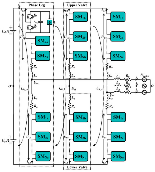
Figure 1.
3-Phase MMC-BESS Generic Structure with HBSM.
In this paper, we will analyze all the SMs for MMC-BESS based on SBs connected in a single stage structure because adding a two-stage structure reduces system efficiency and increases the difficulty of system control, analyzed in [22]. In this paper, we will present a simulation analysis of MMC-BESS with the most suitable SM while, keeping a view of SOC-BC. The submodule topologies Section 2 provides the investigation of different voltage level submodules and their aptness with SBs for MMC-BESS. In power flow and SOC control analysis of MMC-BESS with HBSM Section 3, a detailed power flow and SOC-BC analysis of MMC-BESS has been done to understand the dynamic features of MMC-BESS with SBs. The simulation results and experimental results based Section 4 and Section 5, respectively, present the simulation and hardware prototype results, respectively. Finally, the conclusion is presented in the Section 6.
2. Submodule Topologies
In MMC configuration, a SM is the utmost important and essential building block. In literature, total 36 SM topologies have been found, which were developed to overcome the structural and CC related concerns of MMC. However, in this study, we have found 24 SMs in literature for discussion since, those SMs were initially designed for MMC-HVDC application in which high power rating of each SM is an essential factor to reduce the size of overall system. Furthermore, a single-stage SM structure is considered where batteries are directly integrated in the SMs. Because the capacitor voltages in a single-stage SM of MMC-BESS are directly dependent on battery voltages due to a parallel connection and due to this fact, the capacitor voltage ripple mitigation capability of SMs is not taken into consideration.
At first, these SMs have been developed for MMC-HVDC and medium voltage drive applications but in this study, we have considered them for BESS while, replacing the capacitors in the SMs with SB packs. All the SMs have been analyzed by keeping in view the inconsistency issue of SBs due to the occurrence of unequal SOC over several charge and discharge cycles, and the adaptability of a SM for BESS defines by the complexity of SOC-BC. In this paper, the SMs have been classified according to their output voltage levels and voltages generated in normal operating conditions are considered as voltage levels.
2.1. Two Level SMs
Half-bridge SM is the most common and simplest SM for MMC, Figure 2a. The HBSM is a suitable candidate for MMC-BESS due to its simple structure and it is easy to implement SOC-BC in HBSM based systems due to integration of one battery pack in each SM. When any SM is integrated with one battery pack its SOC-BC control is simple than those SMs, which constitute of more than one battery pack, however, it depends if they can present a parallel current path or not, for battery packs. Nonetheless, HBSM has 0 or VB voltage and it is a reason for the presence of DC component in valve voltages of MMC. Also, due to free-wheeling effect of diodes, it has no DC fault handling capability [23]. So, in case of high power conversion systems, the whole system must shut down during DC faults in the absence of DC circuit breakers (CBs) and it could weaken the functionality of whole system.
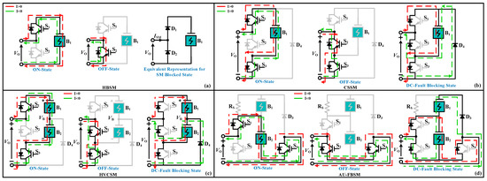
Figure 2.
Two Level SMs. (a) HBSM, (b) CSSM, (c) HVCSM, (d) AU-FBSM.
Clamped Single SM (CSSM) is based on HBSM and it was presented in [24] to mitigate the concern of DC faults without significantly increasing the cost, Figure 2b. For MMC-BESS, it is a good candidate because its SOC-BC is not different to HBSM based system. It is suitable to utilize the CSSM in a hybrid MMC-BESS in combination with HBSM because during DC fault, by blocking all the switching devices, the fault current can flow through redundant SMs while, increasing capability of hybrid system to handle DC-side faults [25]. Under normal operating conditions its conduction losses are more than FBSM due to the fact that S3 remains ON permanently.
Half Voltage Clamped SM (HVCSM) is proposed in [26] to overcome DC-link fault of MMC-HVDC, Figure 2c. However, in case of MMC-BESS with secondary batteries (MMC-BESS-SBs), it is not a suitable SM because during charging process of batteries, it offers a series current path for both SB packs, which will make the SOC-BC more complex. In HVCSM, the component losses are higher than HBSM and lesser than FBSM [27].
Asymmetrical Unipolar FBSM (AU-FBSM): Kim et al. proposed a SM in [28], to overcome DC fault control issue and it is appropriate for hybrid MMC-HVDC, as shown in Figure 2d. Considering it for BESS during normal operation, its structure offers the integration of another battery pack or capacitor to overcome the issue of DC faults. Either way, the SM cost will be high and voltage balancing issues inside the SM would arise, which makes it not suitable for BESS because it would increase the SOC-BC complexity, if VB1 is integrated during faults.
2.2. Three Level SMs
Full-bridge SM offers bipolar voltages VB, −VB, and 0 (ISM > 0) [29], Figure 3a. Due to this, the FBSM can connect either DC or AC system, which is an advantage over HBSM. Therefore, FBSM has double switching devices than HBSM, which increase overall cost and power losses of a system [30]. FBSM also exploits DC-side voltage where HBSM directly delivers nominal voltages [31]. The FBSM offers the same SOC-BC similar to HBSM in addition to DC-side fault mitigation potential with –VB clamping voltage for high power MMC-BESS systems.
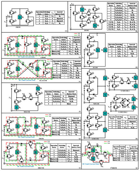
Figure 3.
Three Level SMs and Respective Switching States (a) FBSM, (b) DSMC, (c) CDSM, (d) FCSM, (e) TL-CCSM, (f) MSCSM, (g) IMSM, (h) NPCSM, ANPCSM and T-NPCSMs, (i) HBCSM, (j) T2HBSM.
Double SM Circuit (DSMC), can reduce the CVR of SM at low switching frequencies without increasing the cost and footprint of capacitor, in addition to DC fault mitigation ability [32]. DSMC offers 2VB by making a series connection of two battery packs. To compensate this issue, it offers different switching states, and a parallel connection of batteries, Figure 3b. Although, DSMC has disadvantage of using four switching devices in any current path similar to 5-level SMs.
Clamp-Double SM (CDSM) [30,33] offered a SM as a replacement of series connection of two HBSMs with DC fault mitigation capacity for MMC-HVDC [34], and it also reduces CVR during low-frequency operation [35]. Considering, CDSM in MMC-BESS, its operation is not appropriate as it is suitable in HVDC application due to series connection of two batteries to get voltage 2VB, and it makes the SOC-BC complex due to SBs inconsistency, which will affect SOH of batteries, Figure 3c. For similar voltage levels, the switching losses of CDSM, are lower than FBSM and 35% higher than HBSM.
Flying Capacitor SM (FCSM) is a unipolar SM, which offers 3-level operation with CVR mitigation capacity [36,37]. For MMC-BESS, the SOC-BC issue would arise during the utilization of third switching state in Figure 3d. Due to the fact that FCSM requires; the outer energy storage element must have double energy storage capacity then the inner one to attain 2VB. The utilization of FCSM in BESS requires SOC-BC of two different voltage level battery packs at the same time, which makes it not a suitable SM structure for MMC-BESS.
Three Level Cross-Connected SM (TL-CCSM) is attained from a CDSM and a 5-level cross-connected SM (FL-CCSM), Figure 3e [34]. For MMC-BESS, it is similar to CDSM for 2VB which causes SOC unbalancing. The conduction losses of this SM are equivalent to FBSM and if, we consider higher voltage levels, CDSM is better than TL-CCSM because of parallel current path availability in CDSM in case of DC faults.
Modified Switched Capacitor SM (MSCSM) is an altered version of improved switched capacitor SM (ISCSM) to reduce conduction losses of a SM [38]. During normal operation, it creates a parallel current path for VB like ISCSM, which aids to decrease CC, Figure 3f. Finally, the 2VB is generated by a series connection of two batteries. Since, the batteries have same capacity and their SOCs are forced to be equivalent in a parallel connection, therefore, the SOCs of batteries remain equal during the series connection. MSCSM is a good choice for MMC-BESS than clamped SMs since, it blocks the influence of AC-side current on DC-side faults.
Improved Mixed SM (IMSM) is first proposed for MMC-HVDC to mitigate the parallel coupling effect of capacitors in CDSM [39]. However, for MMC-BESS, it is not suitable due to its requirement of different switching states to attain VB to balance the SOC of two different SBs, Figure 3g. The SOC-BC of IMSM is complicated so, FBSM and HBSM based hybrid MMC-BESSs are better due to their mitigated SOC-BC complexity while, they offer decrease in DC faults.
Neutral Point Clamped SM (NPCSM) has a limited operation region due to loss distribution between switching devices and neutral point voltage balancing [40], Figure 3h. To overcome this concern, the active neutral point clamped SM (ANPCSM) has been proposed in [41,42,43]. The NPCSM and ANPCSM have equivalent semiconducting losses [44]. The NPCSM and ANPCSM have no mitigation capability of DC-side faults. By adding a T-connection at midpoint of two batteries, two more T-SM configurations of NPCSM were presented in [45] with 4-quadrant operation. However, 2VB requires the two SBs in a series connection in all NPCSMs and due to SOH differences of SBs their SOCs will not be balanced, which will eventually effect the output voltage quality [46].
Half-Bridge Clamp SM (HBCSM) contains a series connection of two HBSMs via clamp circuit [34], which halts the DC faults utilizing −2VB, Figure 3i. In HBCSM, −VB is the voltage stress on each device during fault and normal conditions. To compare with FBSM, the HBCSM has lesser electromagnetic interference (EMI) and shoot-through modes. Nevertheless, with all those advantages it suffers from same SOC-BC complexity to attain 2VB like other clamped SMs.
T-Type Half-Bridge based SM (T2HBSM) is presented in [47], which is established on a T-Type connection of HBSM while, offering DC fault mitigation, Figure 3j. It is a good SM for MMC-HVDC but for MMC-BESS, it suffers from same issues like IMSM. If the low switching losses and low device count are not indispensably required then it is not a suitable SM structure for MMC-BESS.
Improved Switched Capacitor SM (ISCSM) uses the batteries in a parallel manner to get VB with a low device count to force their SOC to be equivalent, which aid to attain 2VB voltage without increasing CC in addition to DC faults mitigation ability. Figure 4a [48]. The conduction losses of ISCSM are in between IMSM and TL-CCSM but higher than CDSM with higher device count than MSCSM.
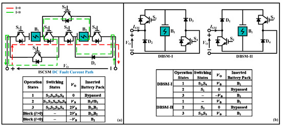
Figure 4.
Three Level SMs and Respective Switching States. (a) ISCSM, (b) DBSM.
Diagonal Bridge SM (DBSM): Two current source DBSMs with low count of IGBTs in comparison with FBSM and CDSM were proposed in [49], Figure 4b. DBSM-1 delivers bipolar voltages during negative valve current and the DBSM-2 delivers bipolar voltages during positive valve current. Therefore, in a two terminal BESS both DBSM structures must be utilized. In MMC-BESS their control is same as FBSM, except with an advantage of a +ve decrease in low switch count.
2.3. Four Level SMs
Semi-Full Bridge SM (SFBSM) is an improved structure of CDSM [50], Figure 5a. The key benefit of SFBSM is its capability to deliver parallel and series connection of secondary battery packs, which could ease SOC-BC in comparison with other 4-level SMs. Nevertheless, the availability of parallel and series connection could prompt of current spikes during the change in switching combinations from parallel to series connection of battery packs due to different SOH of SBs. However, it can be avoided by replacing active switches with diodes in parallel current path. Hence, it is essential to maintain batteries SOCs variation in a small percentage. Overall, this SM could be a good choice in large-scale MMC-BESS.
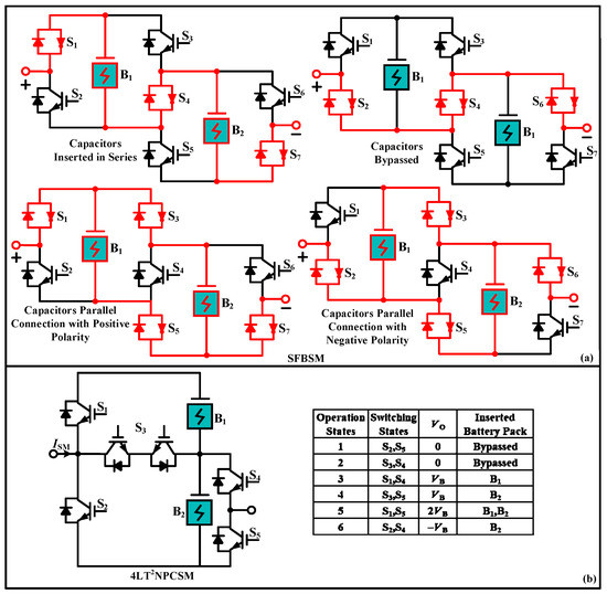
Figure 5.
Four Level SMs and Respective Switching States. (a) SFBSM, (b) 4-LT2NPCSM.
4-Level T-Type NPCSM (4-LT2NPCSM) is based on NPCSM with a potential to abate the SM batteries unbalancing issue by offering the independent operation of SBs by bypassing B1 or B2 to attain VB, Figure 5b [46]. Additionally, due to 2VB it offers lower number of SMs in each valve while, delivering an equivalent output power quality and voltage levels. Nevertheless, S1 and S2 must have higher power ratings in comparison with other switches, which eventually affects the cost of 4-LT2NPCSM. Also, the independent operation of SBs for SOC-BC during VB is complex than those SMs, which deliver a parallel connection of batteries.
2.4. Five Level SMs
Five Level Cross-Connected SM (FL-CCSM) delivers four-quadrant operation, Figure 6a, [51]. When FL-CCSM is used in a combination of 25% ratio with 75% HBSMs in each valve of MMC, it offers a compact system including DC fault mitigation. However, it requires the utilization of different switching states for SOC-BC instead of providing a parallel connection of SBs, which increases the switching losses and CC. It is only suitable for a high power BESS systems, which require −2VB voltage to offer capability against faults.
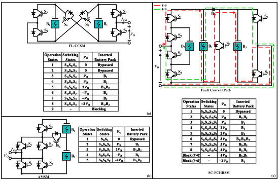
Figure 6.
Five Level SMs and Respective Switching States. (a) FL-CCSM, (b) AMSM (c) SC-FCHBSM.
Asymmetrical Mixed SM (AMSM) is also a four-quadrant operation SM with a 25% less switch count than two series connected FBSMs, Figure 6b, [52]. The drawback of AMSM is the complexity of SOC-BC, which triggers unequal current sharing in the switching process. This asymmetrical current sharing of AMSM instigates the utilization switching devices with different power rating, which rises the cost and losses of overall system.
Series Connected Flying Capacitor with Half Bridge SM (SC-FCHBSM) is established on the series connection of FC and HBSM, including three SBs, Figure 6c, [53]. In this SM, the capacity of B1 and B3 must be double than B2 according to FC structure. The difference in integrated battery capacities makes SOC-BC highly complex. However, different switching states offer different current paths for SOC-BC while, delivering dc fault handling capacity. It is suitable for large-scale MMC-BESS but the cost and footprint are major concerns.
Several SM topologies and their principle operations have been reviewed in this section. A comprehensive overview of all the SMs regarding their design, operation, CC, rating, each SM cost, DC fault handling capability for HVDC and high power MMC-BESS, and SOC-BC complexity for the MMC-BESS medium and high power applications is presented in Table 1. The SM capacitor voltage ripple mitigation capability of SMs is not considered because in a single-stage SMs based MMC-BESS, the capacitor voltage ripple mitigation is not a concern as the capacitor voltages are directly dependent on battery voltages due to parallel connection. In Table 1, VLs, MBV, TS, CS, NC, AD, DC-FHC, CD, CC, SOC-BCC, and TC stands for voltage levels, maximum blocking voltage, total switches, conduction switches, number of capacitor, additional diode, DC fault handling capability, complexity of design, Control complexity, and SOC-BC complexity, respectively.

Table 1.
Comparative Analysis of Different SMs.
Different SMs offer various performance characteristics while, functioning in different operation regions Figure 7, stipulates an operational region comparison of all the SMs which deliver 3-quadrant or 4-quadrant operation. By analyzing all SM structures, so far, HBSM and FBSM structures are the most suitable SMs for MMC-BESS with secondary batteries because they provide a simplest SM SOC-BC among all other SMs. So, for the analysis of MMC-BESS, single-stage half-bridge SM is considered and the next section provides a detailed power flow and SOC-BC analysis of MMC-BESS.
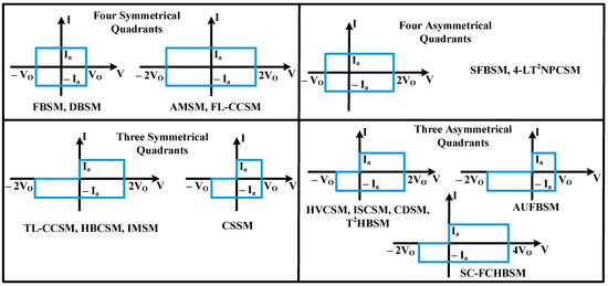
Figure 7.
Operation region of different SMs.
3. Power Flow and SOC Control Analysis of MMC-BESS with HBSM
In previous section, 24 different SM topologies have been studied in detail by categorizing them according to their voltage levels. Some of these topologies are appropriate for MMC-BESS especially, 2-level and 3-level SMs since, each SMs required power rating in case of MMC-BESS is not high as it is not an important factor as it is in MMC-HVDC. So, the higher level SMs would only increase the complexity of control and cost of system. Additionally, among 2-level and 3-level SMs, the HBSM and FBSM are the most appropriate one’s so, for the simplification of analysis, we have considered HBSM based MMC-BESS.
3.1. AC and DC System Analysis
From Figure 1, the circulating currents , the upper and lower valve currents and , the upper and lower valve voltages and , grid side currents , and grid side voltages , are decomposed into both DC and AC components, Figure 8 (j = a, b, c—phase). Similarly, Uac_j is the AC component of the phase-j modulation voltage and it is determined by the AC components of the output side voltages of all modules of upper and lower valves. Uoo′, is the AC component of AC side neutral point reference voltage. Whereas, the instantaneous equations of upper and lower valve currents, and converter AC side j-phase output voltages are:
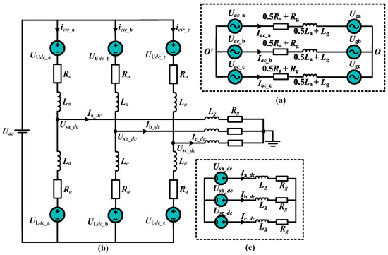
Figure 8.
(a) AC Equivalent Circuit (b) DC Equivalent Circuit (c) Simplified DC Loop.
In MMC-BESS-AC circuit, the AC loop voltage equation is:
In the above equations, is the converter AC side j-phase output voltage, and are the AC components of voltages and , respectively, where and are individual SM output voltages of upper and lower valves of phase-j. is the current flowing from AC side j-phase output voltage towards grid voltages, shown in Figure 8a. From Equation (3), it could be analyzed that the current is determined by voltage difference between phase voltages and grid voltages. Hence, the current could be controlled by controlling the phase voltage because grid voltage remains constant, Figure 9.
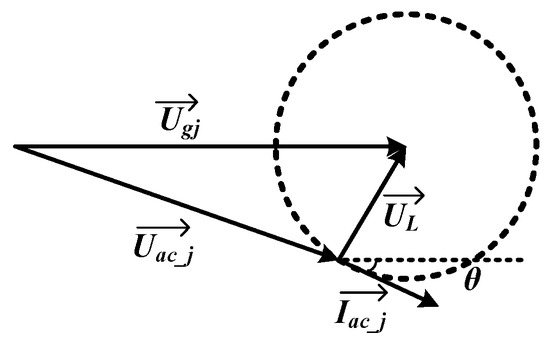
Figure 9.
Voltage Vector of Power Conversion System Control Strategy.
Figure 10, the typical four-quadrant operation of power conversion system in shown, it could be analyzed that when the system is running in positive characteristic operation mode with resistive load when the battery is in discharging state, it means that battery is supplying power to the AC grid, (Figure 10b). And Figure 10d shows that the system is running in negative characteristic operation mode with resistive load when battery is in charging state, it means that AC grid charges the battery.
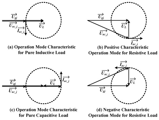
Figure 10.
Typical Cases of the Power Conversion System.
It could be analyzed from Equation (5) that the circulating current can be controlled by controlling and . In ideal cases and without considering equalization, the circuit parameters of each phase must be same. Similarly, the circuit parameters of upper and lower valves would also be same and in this case the DC current would be evenly distributed in 3-phases. According to the above condition and by analyzing DC equivalent circuit, the DC components of upper and lower valve voltages , , , , , are expressed in Equation (8):
Also, there is 3-phase DC output voltages exist on j-phase output voltage of converter AC side and they should meet the following condition:
At this condition, no DC current is injected into the grid. However, in real conditions, due to dispersion of system parameters, the DC voltage offset of 3-phase network is not likely to be zero, so the appropriate suppression method must be applied. The DC voltage component of the grid side could be expressed as:
By adding above equations:
The DC component of the grid side current is determined by the DC voltage component of the grid and the corresponding relation can be derived from grid side DC equivalent loop. A simplified structure of the DC loop connected to the grid is shown in Figure 8c.
According to superposition principle, the DC current flowing in a-phase is the resultant of three DC voltage sources of 3-phase and the symmetry of circuit shows that the current can be regarded as the result equivalent voltage source .
3.2. Power Control of MMC-BESS
The circulating current contains DC components and the harmonic components of nth order and its representation is:
Considering, 3-phase circulating current only contains DC components. During stable operation, the expressions of upper and lower valve modulation voltages of MMC-BESS are:
Above equations represent that the power exchange between MMC-BESS, AC grid, and DC grid can be separately controlled by controlling the AC and DC components of the modulation voltages of the upper and lower valves of each phase.
From Equations (15) and (16), the expressions for AC power control are:
The mathematical model of could be converted into dq rotating reference frame by applying Park transformation, results in DC components, which are easy to control and could represent as:
In vector control, the current control loop regulates and at their reference values, represented by and , by adjusting the output voltage reference values of converter. Using, feedforward decoupling control and PI regulators to control output current, the control equations are:
From above analysis, AC side power control block diagram is shown in Figure 11.
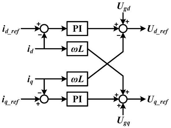
Figure 11.
Power Control Block Diagram of AC-side.
For DC side power control analysis:
From Equation (23), it is clear that the magnitude of circulating current can be controlled by the controlling the and , thereby, achieving DC side power control and the circulating current reference value is 1/3 of DC side current. The PI regulator can be used to control circulating current, thus obtaining DC component values of upper and lower valve output voltage of each phase.
where the circulating current is:
From Equations (25) and (26), the control block diagram of DC side control is shown in Figure 12.
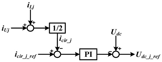
Figure 12.
Control Block Diagram of DC-side.
3.3. SOC Balancing
The MMC-BESS with batteries integrated into the SMs, transfer power with the use of DC-link among three phases. The special feature of MMC-BESS can be used to balance SOC of batteries and also could be used to compensate if a battery in any phase undergoes a fault. In [2], the SOC-BC between different phases has been done by injecting the zero-sequence voltage; however, the zero-sequence voltage injection calculation is very complex, which further leads to complexity of control hardware. In [19], at first, the SOCs of all SMs have sorted out and then SOC-BC control is attained by utilizing carrier based disposition PWM methodology. However, with the increase in number of SMs, the complexity increases, which is a drawback. In [54], a simple close-loop methodology is introduced to attain the SOC-BC within a valve and phase legs, however, the SOC-BC between the upper and lower valves is not considered. Few research articles are focused on the SOC-BC between upper and lower valves via AC circulating current while, the AC circulating current constitutes only the negative and positive sequence components to protect against the current flowing from DC source [55]. In order to increase the battery system’s cycle time, the [56] introduced a methodology based on the AC and DC circulating current control and for SOC tracking, the modulation index of each SM is utilized. In [57], the SOC-BC rebalancing is attained even during fault operation mode and for this purpose, the upper and lower valves capacity energy is controlled by regulating the circulating current after bypassing the faulty SMs. Though, several SOC-BC methodologies have been introduced in literature; however, the capacity in consistency concern has not been completely discussed. In the scenario where the index of inconsistency goes higher, the control error might become greater, which results in the decrease in battery capacity utilization.
To mitigate the shortcomings of conventional SOC-BC methodologies during battery inconsistency operation, on the basis of power control analysis, a SOC-BC control is introduced in which the voltage of each SM can be superimposed with a corresponding component, so that the power of each SM is different, and the balance control of battery SOC in the phase can be realized. In distributed battery system, if the unified charging and discharging control is performed on SM battery, the battery lifetime could be affected due to difference in SOC of the SM battery. The individual battery SOC could be stated as by keeping in view of Figure 1:
In above equation, is the individual battery nominal energy provided by production of its capacity and voltage, is the power of individual battery, for upper and lower valve, and . From Equation (27), it could be analyzed that an individual battery SOC could be controlled via directly regulating the power of corresponding battery. Since, could be different in each SM due to aging factor of battery. Thus, for SOC-BC, the battery capacity must be taken into consideration. Ref. [58] considered the battery capacity for generation of SOC-BC co-efficient. The SOCs used for MMC-BESS are:
In above equations, the and are the SOCs of upper and lower valves, signifies the average SOC of phase-j, is the averaging SOC of all three phases, is the deviation between the SOC of phase-j xth SMs battery and the average SOC of phase-j, is the amount of deviation between the phase-j average and the 3-phase averaging SOC, and , are the SOCs of xth SM battery.
The phase-to-phase SOC-BC is required when the average SOC of all the SM batteries of each phase is different from other after initial or running for a period of time, thus, . Through certain control amendments after a period of time, the SOC of each phase reaches to an approximate equilibrium value, thus, . In this work, the strategy of controlling DC side current component to realize the SOC-BC between phases of the energy storage system is utilized. Under normal operating conditions, the DC side current is evenly distributed among three phases, and the charge and discharge power of SM batteries of each phase are same. Now consider controlling the distribution ratio of DC side interface current in the 3-phases, so that the charge and discharge power of SM battery of each phase is different, and then the balanced control of batteries in each phase could be realized. Figure 13, shows the phase-to-phase SOC-BC depending the DC side current component:

Figure 13.
SOC Balancing between 3-Phases.
For in-phase SOC-BC, consider that the output power of each sub module in each phase will be proportional to its SOC through certain control methods, so as to achieve the purpose of intra-phase equalization. Considering the cascade structure, the current flowing through the SMs in each valve is equal, so the charge and discharge power of the battery is proportional to the voltage of each SM. So, for the unbalanced battery SOC of SMs in the valve, the voltage of each SM can be superimposed with a corresponding component, so that the power of each SM is different, and the balance control of battery SOC in the phase can be realized. According to the previous analysis of MMC-BESS, it can be known that under normal circumstances without balanced control, the voltage output of each SM in upper and lower valve is equivalent in magnitude so, we consider the upper valve of phase-a for analysis. By superimposing as equalized voltage component proportional to the degree of battery SOC imbalance on the basis of voltage of each SM, the in-phase battery SOC can be balanced. Let the valve current flow through each SM could be defined as:
Let the superimposed voltage component on the xth submodule of the upper valve be:
Then the additional power generated by the superimposed voltage component would be:
To use this additional power to eliminate the SOC imbalance of each SM, it is required to make the power of each SM shown in Equation (35), to proportional of SOC imbalance of each SM in the phase.
where K could be obtained from Equation (36), the following relation could be obtained:
Therefore, the superimposed voltage component on each SM can be expressed as:
where λ is the gain, and its value is selected according to the real time requirements of the system. Depending on the above analysis, the control principle of SOC-BC of the valve of a-phase could be obtained. The control block diagram is shown in Figure 14, and Dai(s) is the disturbance caused by switching losses. With reference to the analysis of upper valve of phase-a, the superimposed voltage components of upper and lower valves of phase-b and phase-c could be obtained.

Figure 14.
Schematic Diagram of the SOC Balancing Control of SM in Phase-a.
After obtaining the corresponding voltage component, the additional voltage can be added to the output voltages of each SM. After the addition of in-phase SOC-BC, the modulation signals of each SM of each phase are no longer the same, however, an additional voltage is superimposed. After these different modulation signals are subjected to PSC-PWM, the SOC-BC can be obtained through power control. The PWM control signals of each SM of the balancing control are shown in Figure 15.
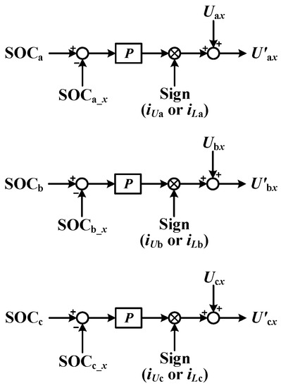
Figure 15.
Principle of Individual SOC Balancing Control of SMs within the same Phase.
4. Simulation Results
Based on the analysis in previous section, the overall power control block diagram of MMC-BESS system can be obtained as shown in Figure 16. The simulation results of MMC-BESS are presented in this section. So, the MMC-BESS structure with eight HBSMs in each valve is simulated to analyze the performance of MMC-BESS and control technique. The converter parameters are shown in Table 2.
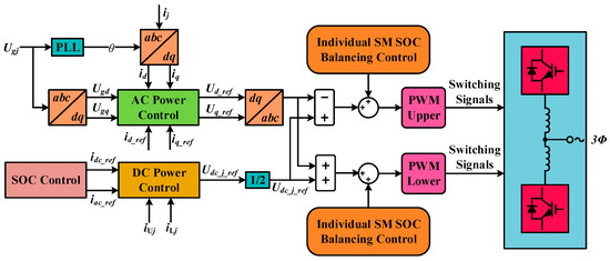
Figure 16.
Control Block Diagram of MMC-BESS.

Table 2.
Simulation Parameters of MMC-BESS.
The above results in Figure 17 shows the operational results of simulation system when the given active current component is 128.6 A, the reactive current component is 0 A, and the given DC current is 70 A (67.2 kW). In Figure 18, the 3-phase output currents of MMC-BESS are shown with peak value of 128.6 A. It is clear from Figure 18 that after 0.1 s the currents are entirely completely balanced with each other and in the power flow mode, the DC side is responsible for power supply to the batteries and ac side power.
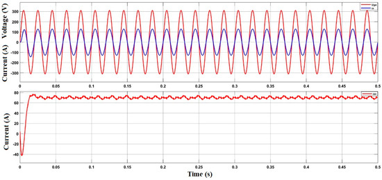
Figure 17.
Power Control Simulation Results of MMC-BESS.
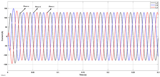
Figure 18.
3-Phase Output Currents of MMC-BESS.
Also, the upper and lower valve current waveforms of phase-a are also shown in Figure 19 and they variate between the −42 A and +88 A.
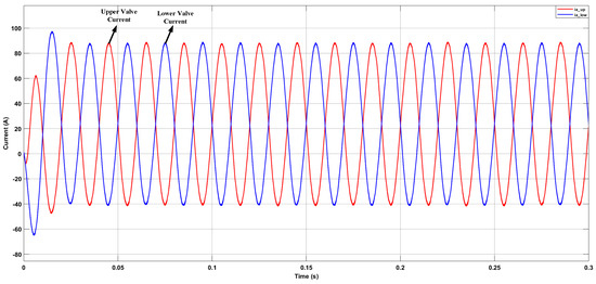
Figure 19.
Upper and Lower Valve Currents.
Figure 20 and Figure 21, gives the transient response of output current of AC and DC side when there is a step change of power command. It can be seen that the output current changes almost immediately and the waveform does not have obvious distortion during the transition.
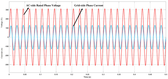
Figure 20.
Step-change of Output Power.
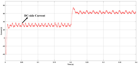
Figure 21.
DC-side Output Current.
In order to verify the effectiveness of SOC control strategy, the SOC initial value of each SM is set differently. The SOCs initial values of all submodule are set from 69% to 73%, and different capacity is preset as stated in Table 3.

Table 3.
Battery’s initial SOC values of SMs under phase-to-phase SOC balance control.
At first, the 3-level SOC balancing in implemented, the given AC-side power is 60 kW and the given DC-side power is 67.2 kW. The battery is charges during this time for 240 s. For the second simulation, the additional voltage is superimposed to the output voltages of each SM, to verify the control technique.
Figure 22, demonstrates the 3-level SOC balancing control simulation results without the superimposed additional voltages in charging mode. Figure 23, demonstrates the 3-level SOC balancing control simulation results conjoined with superimposed additional voltages in charging mode. While, Figure 24 depicts the 3-level SOC balancing control simulation results conjoined with superimposed additional voltages in discharging mode. The Figure 22, only presents the results of 3-level SOC balancing control. The Figure 22a depicts that eventually the SOCs of all the batteries almost converge to each other, however, for the batteries with different capacity, the convergence rate is not good. The maximum difference of SOC of all the batteries is reduced to 0.6%. Moreover, the three- phase leg SOC difference is decreased from 0.45% to 0.2%. From the results it is clear that the battery capacity has an influence on SOC balancing. The SOC difference of upper and lower valve of phase-a is presented in Figure 22c,d, and the SOC difference in less than 0.001% in phase-a with same capacity, however, in phase-b the difference is 0.4% with the different capacity.
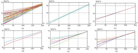
Figure 22.
SOC Balancing Control without the superimposition of additional voltages (a) All 48 battery modules SOCs (b) Phase-to-phase SOC balancing control (c) The SOC balancing control between the upper and lower valves of phase-a (d) The SOC balancing control between the upper and lower valves of phase-b (e) The SOC balancing control of the upper valve of phase-a (f) The SOC balancing control of the upper valve of phase-b.
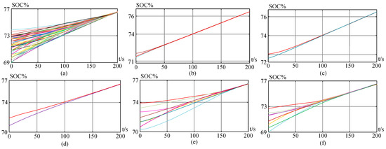
Figure 23.
SOC Balancing Control with the superimposition of additional voltages (a) All 48 battery modules SOCs (b) Phase-to-phase SOC balancing control (c) The SOC balancing control between the upper and lower valves of phase-a (d) The SOC balancing control between the upper and lower valves of phase-b (e) The SOC balancing control of the upper valve of phase-a (f) The SOC balancing control of the upper valve of phase-b.
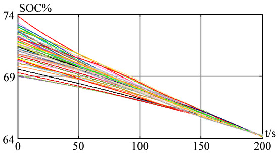
Figure 24.
All 48 battery modules SOC balancing control with the superimposition of additional voltages during the discharge mode.
The Figure 23, presents the results of SOC balancing control based on the superimposition of additional voltages and the convergence of each SM SOC becomes better in comparison with Figure 22. After the superimposition of additional voltages in each bridge cell, the maximum difference of SOC of all the batteries is reduced to 0.1%. Moreover, the three-phase leg SOC difference is decreased to 0.01%, as shown in Figure 23b. The upper and lower valve deviation is also reduced to 0.05% as shown in Figure 23d. Also, in phase-b, the upper and lower valve SOC difference is reduced as well up to 0.05% less than 0.18% presented in Figure 22f. From Figure 22 and Figure 23, it is clear that the 3-level SOC balancing superimposed with additional voltages could balance the batteries with different capacity. Eventually, the 3-level SOC balancing control simulation results conjoined with superimposed additional voltages in discharging mode are shown in Figure 24.
5. Experimental Results
The previous sections mainly studied the possible SM topologies for MMC-BESS and then the power flow control analysis of MMC-BESS with HBSM. In order, verify the power flow control analysis, a downscaled laboratory prototype has been developed with lead-acid batteries. The 3-phase leg prototype is designed with the 48 SMs (8 SMs per valve) with N + 1 voltage levels whose AC-side power is 426.26 W and DC-side power is 840 W. The main parameters are listed in Table 4. Each SM constitutes of four MOSFET’s, offering the user the option to utilize either HBSM, CSSM or FBSM configuration, besides a capacitor with corresponding voltage rating. The SMs circuit boards are mounted on lead-acid batteries where they receive signals from the main controller while, following chain communication between main control board and each phase of MMC-BESS. The integrated battery management system on SM circuit board protects the battery from over and under voltage, over current, and short circuits. Consequently, the purpose of laboratory prototype is to verify the different control modes including, the battery charging and discharging modes, which certainly facilitate the SOC-BC realization of laboratory prototype.

Table 4.
Design Parameters of Prototype.
The schematic of experimental setup configuration of MMC-BESS is shown in Figure 25. The overall control of MMC-BESS is mainly based on chain communication system because it greatly reduces the number of communication interfaces of the main control board FPGA where main control board is based on a DSP and an FPGA along with its peripheral circuits. In the main control board, the DSP is responsible for processing, computing, and delivering the modulation data to the FPGA; while, the FPGA is mainly responsible for the implementation of phase-shift carrier modulation, the communication between the SMs controllers, and send them the control signals. Each SM has its own FPGA, which receives the control information issues by the main controller and analyzes it, and generates two driving signals with a dead time to control the switching devices. At the same time, the SM’s FPGA needs to collect the module voltages and faults status information, and then transmit this collected data back to the main controller through SM’s FPGA with the same transmission protocol code. If the SM has an over-current fault, the SM’s FPGA processes the detected over-current signal and immediately turns off the switching devices to achieve timely and effective local overcurrent protection.
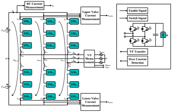
Figure 25.
Schematic of Experimental Circuit Configuration.
The MMC-BESS prototype built in the laboratory is shown in Figure 26. The output phase voltage waveform of the system with eight SMs in each valve is shown in Figure 27a with N + 1 output voltage levels however, in future, the number of SMs in each valve will be increased to increase the power rating of the system and also to get the output voltage levels further closer to sine wave. Along with the 3-phase output voltages, the 3-phase output currents are also shown in the Figure 27b with an amplitude of 10 A. The 3-phase output currents are perfectly aligned with each other which signifies the accuracy of the control technique discussed in previous sections.
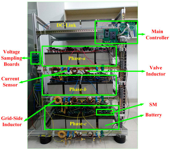
Figure 26.
Laboratory Prototype of MMC-BESS.
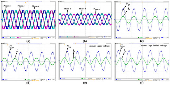
Figure 27.
(a) 3-Phase AC Phase-to-Neutral Voltages (2 V/small division) (b) 3-Phase Output Currents (5 A/division) (c) id = 10 A, Battery Discharging Mode (10 V/division) (d) id = −10 A, Battery Charging Mode (10 V/division) (e) iq = 10 A, Voltage and current waveforms of phase-a with reactive power flow (10 V/division) (f) iq = −10 A, Voltage and current waveforms of phase-a with reactive power flow (10 V/division).
The battery discharging and charging modes of the system are also shown in the Figure 27c,d, respectively. During discharging and charging modes the AC interface current (id) for the active power flow is 10 A and −10 A, respectively. Along with them, the output voltage and current waveforms of phase-a for reactive power flow (141.4 Mvar) with AC interface current (iq) of 10 A and −10 A are shown in Figure 27e,f, respectively. The experimental results of SOC-BC of 3-level MMC-BESS are shown in Figure 28. In Figure 28a, the SOCs of all the battery modules are presented and it depicts that the difference between the SOCs at the start is 15.64%, which decreases to 1.67% when it was close to 40 min, therefore, the effectiveness of the proposed SOC-BEC is verified. In Figure 28b,c, the phase-to-phase SOC balancing control and the SOC balancing control between the upper and lower valves of 3-phases are shown, respectively. The phase-to-phase and the upper and lower valves of 3-phases SOC results are as expected and they are converging towards the equilibrium state.
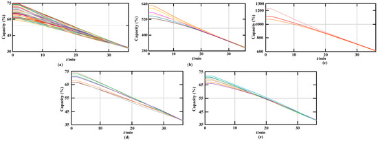
Figure 28.
The experimental results of SOC-BC (a) All 48 battery modules SOCs (b) Phase-to-phase SOC balancing control (c) The SOC balancing control between the upper and lower valves of phase-a (d) The SOC balancing control of the upper valve of phase-b (e) The SOC balancing control of the lower valve of phase-b 3-Phase Output Currents.
It verifies that the proposed methodology and the results are in convergence with the expected results as it states in the simulation results. So, all the experimental results signify that the MMC-BESS is accurately working in different power flow control modes, and in future, the power rating of the system could be increased and for that the FBSM or CSSM configuration could be utilized while, considering the DC fault current control issue.
6. Conclusions
In this paper, the potential of MMC structure is exploited for the integration of small battery packs in a split accumulation to develop a battery energy storage system, which easily avoids the short board effect of series and parallel connection of batteries. A detailed study on different SM topologies has been done considering the SOC-BC complexity level while, utilizing different SMs for MMC-BESS. The complexity level of SOC-BC increases with the increase in SM output voltage levels and their incapability to offer a parallel current path during normal operation for different secondary battery packs integrated into the SMs. On the basis of study in Section II, the MMC-BESS based on HBSM is considered for investigation since, the most suitable SMs for MMC-BESS are HBSM, CSSM, and FBSM. For the investigation of MMC-BESS, it is split into AC and DC equivalent circuits. According to the AC and DC equivalent circuits, the corresponding mathematical models were developed. On the basis of these models, the AC and DC-side power controls were acquired and verified by simulations along with the SOC-BC considering batteries inconsistency. Conclusively, a downscaled laboratory prototype has been developed to carry out the power control experiments and its results verified the operating scenarios of such a converter structure. In future works, the control and prototype will be analyzed in different grid operating conditions. The SOC-BC will be further optimized and the work of SOC-BC optimization in scenario of different SM topologies could lead to the development of a new SM topology, which would be more appropriate for MMC-BESS operating conditions.
Author Contributions
Conceptualization: S.A., S.B. and M.M.K.; Investigation: S.A., S.B., M.M.K., A.T., P.P.P. and Y.-C.B.; Methodology: S.A., S.B. and M.M.K.; Software: S.A., S.B. and M.M.K.; Supervision: S.B. and M.M.K.; Validation: S.B. and M.M.K.; Writing—original draft preparation: S.A., S.B. and M.M.K.; Writing—review & editing: S.A., S.B., M.M.K., A.T., P.P.P. and Y.-C.B.; Funding acquisition: Y.-C.B. All authors have read and agreed to the published version of the manuscript.
Funding
The research was financially supported by the Ministry of Small and Medium-sized Enterprises (SMEs) and Startups (MSS), Korea, under the “Regional Specialized Industry Development Plus Program (R&D, S3246057)” supervised by the Korea Institute for Advancement of Technology (KIAT). And, this work was also supported by the Korea Institute for Advancement of Technology (KIAT) grant funded by the Korea Government (MOTIE) (P0016977, The Establishment Project of Industry-University Fusion District).
Acknowledgments
We thank the reviewers’ for their useful comments and suggestion.
Conflicts of Interest
The authors declare no conflict of interest.
Abbreviations
| BESS | Battery Energy Storage System |
| PCS | Power Conversion System |
| MMC | Modular Multilevel Converter |
| MMC-BESS-SBs | MMC-BESS with Secondary Batteries |
| SOC-BC | State of Charge Balancing Control |
| SMs | Submodules |
| CC | Control Complexity |
| HBSM | Half-Bridge Submodule |
| FBSM | Full-Bridge Submodule |
| CVR | Capacitor Voltage Ripple |
| CBs | Circuit Breakers |
| CSSM | Clamped Single Submodule |
| HVCSM | Half Voltage Clamped Submodule |
| AU-FBSM | Asymmetrical Unipolar Full-Bridge Submodule |
| DSMC | Double Submodule Circuit |
| SOH | State of Health |
| CDSM | Clamp-Double Submodule |
| FCSM | Flying Capacitor Submodule |
| TL-CCSM | Three Level Cross-Connected Submodule |
| MSCSM | Modified Switched Capacitor Submodule |
| ISCSM | Improved Switched Capacitor Submodule |
| IMSM | Improved Mixed Submodule |
| NPCSM | Neutral Point Clamped Submodule |
| ANPCSM | Active Neutral Point Clamped Submodule |
| T-NPCSM | T-Type Neural Point Clamped Submodule |
| HBCSM | Half-Bridge Clamp Submodule |
| T2HBSM | T-Type Half-Bridge based Submodule |
| ISCSM | Improved Switched Capacitor Submodule |
| DBSM | Diagonal Bridge Submodule |
| MMCSC | Modular Multilevel Current Source Converter |
| SFBSM | Semi-Full Bridge Submodule |
| 4-LT2NPCSM | 4-Level T-Type NPCSM |
| FL-CCSM | Five Level Cross-Connected Submodule |
| AMSM | Asymmetrical Mixed Submodule |
| SC-FCHBSM | Series Connected Flying Capacitor with Half Bridge Submodule |
| VLs | Voltage Levels |
| MBV | Maximum Blocking Voltage |
| TS | Total Switches |
| CS | Conduction Switches |
| NC | Number of Capacitor |
| AD | Additional Diode |
| DC-FHC | DC Fault Handling Capability |
| CD | Complexity of Design |
| SOC-BCC | State of Charge Balancing Control Complexity |
References
- Dell, R.M.; Rand, D.A.J. Energy Storage—A Key Technology for Global Energy Sustainability. J. Power Sources 2001, 100, 2–17. [Google Scholar] [CrossRef]
- Vasiladiotis, M.; Rufer, A. Analysis and Control of Modular Multilevel Converters With Integrated Battery Energy Storage. IEEE Trans. Power Electron. 2015, 30, 163–175. [Google Scholar] [CrossRef]
- Hadjipaschalis, I.; Poullikkas, A.; Efthimiou, V. Overview of Current and Future Energy Storage Technologies for Electric Power Applications. Renew. Sustain. Energy Rev. 2009, 13, 1513–1522. [Google Scholar] [CrossRef]
- Jafari, S.; Shahbazi, Z.; Byun, Y.-C. Lithium-Ion Battery Health Prediction on Hybrid Vehicles Using Machine Learning Approach. Energies 2022, 15, 4753. [Google Scholar] [CrossRef]
- Jafari, S.; Shahbazi, Z.; Byun, Y.; Lee, S.-J. Lithium-Ion Battery Estimation in Online Framework Using Extreme Gradient Boosting Machine Learning Approach. Mathematics 2022, 10, 888. [Google Scholar] [CrossRef]
- Soong, T.; Lehn, P.W. Evaluation of Emerging Modular Multilevel Converters for BESS Applications. IEEE Trans. Power Deliv. 2014, 29, 2086–2094. [Google Scholar] [CrossRef]
- Kouro, S.; Malinowski, M.; Gopakumar, K.; Pou, J.; Franquelo, L.G.; Wu, B.; Rodriguez, J.; Perez, M.A.; Leon, J.I. Recent Advances and Industrial Applications of Multilevel Converters. IEEE Trans. Ind. Electron. 2010, 57, 2553–2580. [Google Scholar] [CrossRef]
- Rodriguez, J.; Bernet, S.; Wu, B.; Pontt, J.O.; Kouro, S. Multilevel Voltage-Source-Converter Topologies for Industrial Medium-Voltage Drives. IEEE Trans. Ind. Electron. 2007, 54, 2930–2945. [Google Scholar] [CrossRef]
- Malinowski, M.; Gopakumar, K.; Rodriguez, J.; Perez, M.A. A Survey on Cascaded Multilevel Inverters. IEEE Trans. Ind. Electron. 2010, 57, 2197–2206. [Google Scholar] [CrossRef]
- Tian, K.; Ali, S.; Huang, Z.; Ling, Z. Power Control and Experiment of 2MW/10kV Cascaded H-Bridge Power Conversion System for Battery Energy Storage System. In Proceedings of the 8th Renewable Power Generation Conference (RPG 2019), Shanghai, China, 24–25 October 2019; pp. 1–7. [Google Scholar] [CrossRef]
- Guan, M.; Xu, Z. Modeling and Control of a Modular Multilevel Converter-Based HVDC System Under Unbalanced Grid Conditions. IEEE Trans. Power Electron. 2012, 27, 4858–4867. [Google Scholar] [CrossRef]
- Ilves, K.; Antonopoulos, A.; Norrga, S.; Nee, H. A New Modulation Method for the Modular Multilevel Converter Allowing Fundamental Switching Frequency. In Proceedings of the 8th International Conference on Power Electronics—ECCE Asia, Jeju, Republic of Korea, 30 May–3 June 2011; pp. 991–998. [Google Scholar] [CrossRef]
- Lesnicar, A.; Marquardt, R. A New Modular Voltage Source Inverter Topology. In Proceedings of the EPE 2003, 10th European Conference on Power Electronics and Applications, Toulouse, France, 2–September 2003. [Google Scholar]
- Trintis, I.; Munk-Nielsen, S.; Teodorescu, R. A Ne4 w Modular Multilevel Converter with Integrated Energy Storage. In Proceedings of the IECON 2011—37th Annual Conference of the IEEE Industrial Electronics Society, Melbourne, VIC, Australia, 7–10 November 2011; pp. 1075–1080. [Google Scholar] [CrossRef]
- Perez, M.A.; Arancibia, D.; Kouro, S.; Rodriguez, J. Modular Multilevel Converter with Integrated Storage for Solar Photovoltaic Applications. In Proceedings of the IECON 2013—39th Annual Conference of the IEEE Industrial Electronics Society, Vienna, Austria, 10–13 November 2013; pp. 6993–6998. [Google Scholar] [CrossRef]
- Ali, S.; Ling, Z.; Tian, K.; Huang, Z. Recent Advancements in Submodule Topologies and Applications of MMC. IEEE J. Emerg. Sel. Top. Power Electron. 2020, 9, 3407–3435. [Google Scholar] [CrossRef]
- Neubauer, J.; Pesaran, A. The Ability of Battery Second Use Strategies to Impact Plug-in Electric Vehicle Prices and Serve Utility Energy Storage Applications. J. Power Sources 2011, 196, 10351–10358. [Google Scholar] [CrossRef]
- Ali, S.; Tian, K.; Huang, Z.; Ling, Z. Comparison of Modulation and Power Control between Modular Multilevel Converter Based Large Scale Battery Energy Storage System and MMC-HVDC. In Proceedings of the 8th International Conference on Renewable Power Generation, Shanghai, China, 24–25 October 2019. [Google Scholar] [CrossRef]
- Quraan, M.; Yeo, T.; Tricoli, P. Design and Control of Modular Multilevel Converters for Battery Electric Vehicles. IEEE Trans. Power Electron. 2016, 31, 507–517. [Google Scholar] [CrossRef]
- Xu, B.; Tu, H.; Du, Y.; Yu, H.; Liang, H.; Lukic, S. A Distributed Control Architecture for Cascaded H-Bridge Converter With Integrated Battery Energy Storage. IEEE Trans. Ind. Appl. 2021, 57, 845–856. [Google Scholar] [CrossRef]
- Mukherjee, N.; Strickland, D. Analysis and Comparative Study of Different Converter Modes in Modular Second-Life Hybrid Battery Energy Storage Systems. IEEE J. Emerg. Sel. Top. Power Electron. 2016, 4, 547–563. [Google Scholar] [CrossRef]
- Huang, Z.; Tian, K.; Ali, S.; Ling, Z. Analysis and Comparison of Power Quality and Inter-Phase Circulation for One-Stage and Two-Stage Modular Battery Energy Storage System. In Proceedings of the 8th Renewable Power Generation Conference (RPG 2019), Shanghai, China, 24–25 October 2019; pp. 1–7. [Google Scholar] [CrossRef]
- Chen, Q.; Li, R.; Cai, X. Analysis and Fault Control of Hybrid Modular Multilevel Converter With Integrated Battery Energy Storage System. IEEE J. Emerg. Sel. Top. Power Electron. 2017, 5, 64–78. [Google Scholar] [CrossRef]
- Zhao, P.; Wang, C.; Xu, J.; Zong, B.; Zhao, C. A Sub-Module Topology of Mmc with DC Fault Ride-through Capability. Power Syst. Technol. 2014, 38, 3441–3446. [Google Scholar] [CrossRef]
- Xu, J.; Zhao, P.; Zhao, C. Reliability Analysis and Redundancy Configuration of MMC With Hybrid Submodule Topologies. IEEE Trans. Power Electron. 2016, 31, 2720–2729. [Google Scholar] [CrossRef]
- Li, X.; Liu, W.; Song, Q.; Rao, H.; Xu, S. An Enhanced MMC Topology with DC Fault Ride-through Capability. In Proceedings of the IECON 2013—39th Annual Conference of the IEEE Industrial Electronics Society, Vienna, Austria, 10–13 November 2013; pp. 6182–6188. [Google Scholar] [CrossRef]
- Konstantinou, G.; Zhang, J.; Ceballos, S.; Pou, J.; Agelidis, V.G. Comparison and Evaluation of Sub-Module Configurations in Modular Multilevel Converters. In Proceedings of the 2015 IEEE 11th International Conference on Power Electronics and Drive Systems, Sydney, NSW, Australia, 9–12 June 2015; pp. 958–963. [Google Scholar] [CrossRef]
- Kim, H.; Kang, J.; Kim, S.; Kim, C.; Hur, K. DC Fault Protection for Modular Multilevel Converter HVDC Using Asymmetrical Unipolar Full-Bridge Submodule. In Proceedings of the 2015 9th International Conference on Power Electronics and ECCE Asia (ICPE-ECCE Asia), Sapporo, Japan, 21–24 June 2015; pp. 1083–1089. [Google Scholar] [CrossRef]
- Zeng, R.; Xu, L.; Yao, L.; Williams, B.W. Design and Operation of a Hybrid Modular Multilevel Converter. IEEE Trans. Power Electron. 2015, 30, 1137–1146. [Google Scholar] [CrossRef]
- Marquardt, R. Modular Multilevel Converter: An Universal Concept for HVDC-Networks and Extended DC-Bus-Applications. In Proceedings of the The 2010 International Power Electronics Conference—ECCE ASIA, Sapporo, Japan, 21–24 June 2010; pp. 502–507. [Google Scholar] [CrossRef]
- Lebre, J.R.; Watanabe, E.H. Fullbridge MMC Control for Hybrid HVDC Systems. In Proceedings of the 2017 Brazilian Power Electronics Conference (COBEP), Juiz de Fora, Brazil, 19–22 November 2017; pp. 1–6. [Google Scholar] [CrossRef]
- Ilves, K.; Taffner, F.; Norrga, S.; Antonopoulos, A.; Harnefors, L.; Nee, H. A Submodule Implementation for Parallel Connection of Capacitors in Modular Multilevel Converters. In Proceedings of the 2013 15th European Conference on Power Electronics and Applications (EPE), Lille, France, 3–5 September 2013; pp. 1–10. [Google Scholar] [CrossRef]
- Marquardt, R. Modular Multilevel Converter Topologies with DC-Short Circuit Current Limitation. In Proceedings of the 8th International Conference on Power Electronics—ECCE Asia, Jeju, Republic of Korea, 30 May–3 June 2011; pp. 1425–1431. [Google Scholar] [CrossRef]
- Qin, J.; Saeedifard, M.; Rockhill, A.; Zhou, R. Hybrid Design of Modular Multilevel Converters for HVDC Systems Based on Various Submodule Circuits. IEEE Trans. Power Deliv. 2015, 30, 385–394. [Google Scholar] [CrossRef]
- Grégoire, L.; Blanchette, H.F.; Li, W.; Antonopoulos, A.; Ängquist, L.; Al-Haddad, K. Modular Multilevel Converters Overvoltage Diagnosis and Remedial Strategy During Blocking Sequences. IEEE Trans. Power Electron. 2015, 30, 2777–2785. [Google Scholar] [CrossRef]
- Dekka, A.; Wu, B.; Zargari, N.R.; Fuentes, R.L. Dynamic Voltage Balancing Algorithm for Modular Multilevel Converter: A Unique Solution. IEEE Trans. Power Electron. 2016, 31, 952–963. [Google Scholar] [CrossRef]
- Lizana, R.; Perez, M.; Dekka, A.; Wu, B. Capacitor Voltage Balancing Method for Modular Multilevel Converter with Flying Capacitor Submodules. In Proceedings of the 2017 IEEE International Conference on Industrial Technology (ICIT), Toronto, ON, Canada, 22–25 March 2017; pp. 60–65. [Google Scholar] [CrossRef]
- Sallam, A.; Hamdy, R.A.R.; Moustafa, M.M.Z.; Hossam-Eldin, A. New Topology for Three-Level Modified Switched Capacitor Submodule for Modular Multilevel Converter with DC Fault Blocking Capability. In Proceedings of the 2017 19th European Conference on Power Electronics and Applications (EPE’17 ECCE Europe), Warsaw, Poland, 11–14 September 2017; pp. 1–9. [Google Scholar] [CrossRef]
- Zhang, J.; Zhao, C.; Guo, L. Simulation Analysis on Submodule Topology of Modular Multilevel Converter. Autom. Electr. Power Syst. 2015, 39, 106–111. [Google Scholar] [CrossRef]
- Solas, E.; Abad, G.; Barrena, J.A.; Aurtenetxea, S.; Cárcar, A.; Zając, L. Modular Multilevel Converter With Different Submodule Concepts—Part I: Capacitor Voltage Balancing Method. IEEE Trans. Ind. Electron. 2013, 60, 4525–4535. [Google Scholar] [CrossRef]
- Rodriguez, J.; Bernet, S.; Steimer, P.K.; Lizama, I.E. A Survey on Neutral-Point-Clamped Inverters. IEEE Trans. Ind. Electron. 2010, 57, 2219–2230. [Google Scholar] [CrossRef]
- Barbosa, P.; Steimer, P.; Meysenc, L.; Winkelnkemper, M.; Steinke, J.; Celanovic, N. Active Neutral-Point-Clamped Multilevel Converters. In Proceedings of the 2005 IEEE 36th Power Electronics Specialists Conference, Dresden, Germany, 16 June 2005; pp. 2296–2301. [Google Scholar] [CrossRef]
- Bruckner, T.; Bemet, S. Loss Balancing in Three-Level Voltage Source Inverters Applying Active NPC Switches. In Proceedings of the 2001 IEEE 32nd Annual Power Electronics Specialists Conference (IEEE Cat. No.01CH37230), Vancouver, BC, Canada, 17–21 June 2001; Volume 2, pp. 1135–1140. [Google Scholar] [CrossRef]
- Soeiro, T.B.; Kolar, J.W. Novel 3-Level Hybrid Neutral-Point-Clamped Converter. In Proceedings of the IECON 2011—37th Annual Conference of the IEEE Industrial Electronics Society, Melbourne, VIC, Australia, 7–10 November 2011; pp. 4457–4462. [Google Scholar] [CrossRef]
- Sahoo, A.K.; Otero-De-Leon, R.; Chandrasekaran, V.; Mohan, N. New 3-Level Submodules for a Modular Multilevel Converter Based HVDC System with Advanced Features. In Proceedings of the IECON 2013—39th Annual Conference of the IEEE Industrial Electronics Society, Vienna, Austria, 10–13 November 2013; pp. 6269–6274. [Google Scholar] [CrossRef]
- Nami, A.; Adabi, J. A New T-Type NPC-Based Submodule for Modular Multilevel Cascaded Converters. In Proceedings of the The 5th Annual International Power Electronics, Drive Systems and Technologies Conference (PEDSTC 2014), Tehran, Iran, 5–6 February 2014; pp. 137–142. [Google Scholar] [CrossRef]
- Zhao, F.; Xiao, G.; Yang, D.; Liu, M.; Han, X.; Liu, B. A Novel T-Type Half-Bridge Cell for Modular Multilevel Converter with DC Fault Blocking Capability. In Proceedings of the 2016 IEEE Energy Conversion Congress and Exposition (ECCE), Milwaukee, WI, USA, 18–22 September 2016; pp. 1–6. [Google Scholar] [CrossRef]
- Elserougi, A.A.; Massoud, A.M.; Ahmed, S. A Switched-Capacitor Submodule for Modular Multilevel HVDC Converters With DC-Fault Blocking Capability and a Reduced Number of Sensors. IEEE Trans. Power Deliv. 2016, 31, 313–322. [Google Scholar] [CrossRef]
- Yu, X.; Wei, Y.; Jiang, Q. New Submodule Circuits for Modular Multilevel Current Source Converters with DC Fault Ride through Capability. In Proceedings of the 2016 IEEE Applied Power Electronics Conference and Exposition (APEC), Long Beach, CA, USA, 20–24 March 2016; pp. 1468–1474. [Google Scholar] [CrossRef]
- Ilves, K.; Bessegato, L.; Harnefors, L.; Norrga, S.; Nee, H. Semi-Full-Bridge Submodule for Modular Multilevel Converters. In Proceedings of the 2015 9th International Conference on Power Electronics and ECCE Asia (ICPE-ECCE Asia), Seoul, Republic of Korea, 1–5 June 2015; pp. 1067–1074. [Google Scholar] [CrossRef]
- Nami, A.; Wang, L.; Dijkhuizen, F.; Shukla, A. Five Level Cross Connected Cell for Cascaded Converters. In Proceedings of the 2013 15th European Conference on Power Electronics and Applications (EPE), Lille, France, 2–6 September 2013; pp. 1–9. [Google Scholar] [CrossRef]
- Mondal, G.; Nielebock, S. Reduced Switch Count 5-Level Modules for Modular Multi-Level Converters. In Proceedings of the IECON 2018-44th Annual Conference of the IEEE Industrial Electronics Society, Washington, DC, USA, 21–23 October 2018. [Google Scholar] [CrossRef]
- Lizana, R.; Dekka, A.; Rivera, S.; Wu, B. Modular Multilevel Converter Based on 5-Level Submodule with DC Fault Blocking Capability. In Proceedings of the IECON 2016—42nd Annual Conference of the IEEE Industrial Electronics Society, Florence, Italy, 23–26 October 2016; pp. 3482–3487. [Google Scholar] [CrossRef]
- Zhang, L.; Gao, F.; Li, N.; Zhang, Q.; Wang, C. Interlinking Modular Multilevel Converter of Hybrid AC-DC Distribution System with Integrated Battery Energy Storage. In Proceedings of the 2015 IEEE Energy Conversion Congress and Exposition (ECCE), Montreal, QC, Canada, 20–24 September 2015; pp. 70–77. [Google Scholar] [CrossRef]
- Quraan, M.; Tricoli, P.; D’Arco, S.; Piegari, L. Efficiency Assessment of Modular Multilevel Converters for Battery Electric Vehicles. IEEE Trans. Power Electron. 2017, 32, 2041–2051. [Google Scholar] [CrossRef]
- Diao, W.; Jiang, J.; Zhang, C.; Liang, H.; Pecht, M. Energy State of Health Estimation for Battery Packs Based on the Degradation and Inconsistency. Energy Procedia 2017, 142, 3578–3583. [Google Scholar] [CrossRef]
- Hillers, A.; Biela, J. Fault-Tolerant Operation of the Modular Multilevel Converter in an Energy Storage System Based on Split Batteries. In Proceedings of the 2014 16th European Conference on Power Electronics and Applications, Lappeenranta, Finland, 26–28 August 2014; pp. 1–8. [Google Scholar] [CrossRef]
- Liang, H.; Guo, L.; Song, J.; Yang, Y.; Zhang, W.; Qi, H. State-of-Charge Balancing Control of a Modular Multilevel Converter with an Integrated Battery Energy Storage. Energies 2018, 11, 873. [Google Scholar] [CrossRef]
Disclaimer/Publisher’s Note: The statements, opinions and data contained in all publications are solely those of the individual author(s) and contributor(s) and not of MDPI and/or the editor(s). MDPI and/or the editor(s) disclaim responsibility for any injury to people or property resulting from any ideas, methods, instructions or products referred to in the content. |
© 2022 by the authors. Licensee MDPI, Basel, Switzerland. This article is an open access article distributed under the terms and conditions of the Creative Commons Attribution (CC BY) license (https://creativecommons.org/licenses/by/4.0/).