
Improving the Reverberation Chamber Performance Using a Reconfigurable Source Stirring Antenna Array


Abstract
:1. Introduction
2. Measurement Setup
3. Measurement Results
4. Conclusions
Author Contributions
Funding
Institutional Review Board Statement
Informed Consent Statement
Data Availability Statement
Conflicts of Interest
References
- IEC 61000-4-21:2001; Electromagnetic Compatibility (EMC)—Part 4-21: Testing and Measurement Techniques—Reverberation Chamber Test Methods. IEC Standard: Geneva, Switzerland, 2011.
- CTIA. Test Plan for Wireless Large-Form-Factor Device Over-the-Air Performance, Ver. 1.2.1, February 2019. Available online: https://www.ctia.org/about-ctia/programs/certification-resources (accessed on 1 July 2017).
- Kildal, P.; Chen, X.; Orlenius, C.; Franzen, M.; Patane, C. Characterization of Reverberation Chambers for OTA Measurements of Wireless Devices: Physical Formulations of Channel Matrix and New Uncertainty Formula. IEEE Trans. Antennas Propag. 2012, 60, 3875–3891. [Google Scholar] [CrossRef] [Green Version]
- Holloway, C.; Hill, D.; Ladbury, J.; Wilson, P.; Koepke, G.; Coder, J. On the Use of Reverberation Chambers to Simulate a Rician Radio Environment for the Testing of Wireless Devices. IEEE Trans. Antennas Propag. 2006, 54, 3167–3177. [Google Scholar] [CrossRef]
- XU, Q.; Huang, Y. Anechoic and Reverberation Chambers: Theory, Design and Measurements; Wiley-IEEE: Blackwell, UK, 2019. [Google Scholar]
- Kildal, P.; Carlsson, C. Detection of a polarization imbalance in reverberation chambers and how to remove it by polarization stirring when measuring antenna efficiencies. Microw. Opt. Technol. Lett. 2002, 34, 145–149. [Google Scholar] [CrossRef]
- Alibakhshikenari, M.; Babaeian, F.; Virdee, B.S.; Aissa, S.; Azpilicueta, L.; See, C.H.; Althuwayb, A.A.; Huynen, I.; Abd-Alhameed, R.A.; Falcone, F.; et al. A Comprehensive Survey on “Various Decoupling Mechanisms with Focus on Metamaterial and Metasurface Principles Applicable to SAR and MIMO Antenna Systems. IEEE Access 2020, 8, 192965–193004. [Google Scholar] [CrossRef]
- Althuwayb, A. Low-Interacted Multiple Antenna Systems Based on Metasurface-Inspired Isolation Approach for MIMO Applications. Arab. J. Sci. Eng. 2021, 47, 2629–2638. [Google Scholar] [CrossRef]
- Alibakhshikenari, M.; Virdee, B.S.; Shukla, P.; See, C.H.; Abd-Alhameed, R.A.; Falcone, F.; Quazzane, K.; Limiti, E. Isolation enhancement of densely packed array antennas with periodic MTM-photonic bandgap for SAR and MIMO systems. IET Microw. Antennas Propag. 2020, 14, 183–188. [Google Scholar] [CrossRef]
- Maleki, A.; Oskouei, H.; Shirkolaei, M.M. Miniaturized microstrip patch antenna with high inter-port isolation for full duplex communication system. Int. J. RF Microw. Comput.-Aided Eng. 2021, 31, e22760. [Google Scholar] [CrossRef]
- Xu, Q.; Xing, L.; Zhao, Y.; Loh, T.; Wang, M.; Huang, Y. Approximate Analytical Equations for the Stirrer Angular Correlation in a Reverberation Chamber. IEEE Trans. Electromagn. Compat. 2019, 61, 1707–1713. [Google Scholar] [CrossRef]
- Hill, D.A. Electromagnetic Fields in Cavities: Deterministic and Statistical Theories; Wiley-IEEE Press: Hoboken, NJ, USA, 2009. [Google Scholar]
- Besnier, P.; Démoulin, B. Electromagnetic Reverberation Chambers, APS Meeting Abstracts; John Wiley & Sons: Hoboken, NJ, USA, 2013. [Google Scholar]
- Xu, Q.; Huang, Y.; Xing, L.; Tian, Z. Extract the Decay Constant of a Reverberation Chamber without Satisfying Nyquist Criterion. IEEE Microw. Wirel. Compon. Lett. 2016, 26, 153–155. [Google Scholar] [CrossRef]
- Huang, Y. The Investigation of Chambers for Electromagnetic Systems. Ph.D. Thesis, University of Oxford, Oxford, UK, 1993. [Google Scholar]
- Cerri, G.; Primiani, V.; Pennesi, S.; Russo, P. Source Stirring Mode for Reverberation Chambers. IEEE Trans. Electromagn. Compat. 2005, 47, 815–823. [Google Scholar] [CrossRef]
- Chen, X.; Kildal, P.; Lai, S.-H. Estimation of Average Rician K-Factor and Average Mode Bandwidth in Loaded Reverberation Chamber. IEEE Antennas Wirel. Propag. Lett. 2011, 10, 1437–1440. [Google Scholar] [CrossRef]
- Chen, X.; Kildal, P.-S.; Carlsson, J. Determination of maximum doppler shift in reverberation chamber using level crossing rate. In Proceedings of the 5th European Conference on Antennas and Propagation (EUCAP), Rome, Italy, 11–15 April 2011; pp. 62–65. [Google Scholar]
- Leo, A.; Cerri, G.; Russo, P.; Primiani, V. Experimental Validation of an Analytical Model for the Design of Source-Stirred Chambers. IEEE Trans. Electromagn. Compat. 2018, 60, 540–543. [Google Scholar] [CrossRef]
- Baba, I.E.; Lallechere, S.; Bonnet, P.; Benoit, J.; Paladian, F. Computing total scattering cross section from 3-D reverberation chambers time modeling. In Proceedings of the 2012 Asia-Pacific Symposium on Electromagnetic Compatibility, Singapore, 21–24 May 2012; pp. 585–588. [Google Scholar]


| Title 1 | Stirring Scenario | Hybrid Stirring |
|---|---|---|
| Reconfigurable source stirring | Feed seven antennas in sequence and repeat rotating for each antenna | ☑Feed antenna array ☑Rotate antenna array ☒Rotate metal stirrers |
| Conventional mechanical stirring | Rotate the metal stirrers, and V and H stirrers | ☒Feed antenna array ☒Rotate antenna array ☑Rotate metal stirrers |
| Mechanical stirring of antenna array | Rotate the antenna array without feeding | ☒Feed antenna array ☑Rotate antenna array ☒Rotate metal stirrers |
| Source stirring of antenna array | Feeding the seven antennas in sequence without rotating | ☑Feed antenna array ☒Rotate antenna array ☒Rotate metal stirrers |
| Reconfigurable Source Stirring | Conventional Mechanical Stirring | Mechanical Stirring of Antenna Array | Source Stirring of Antenna Array | |
|---|---|---|---|---|
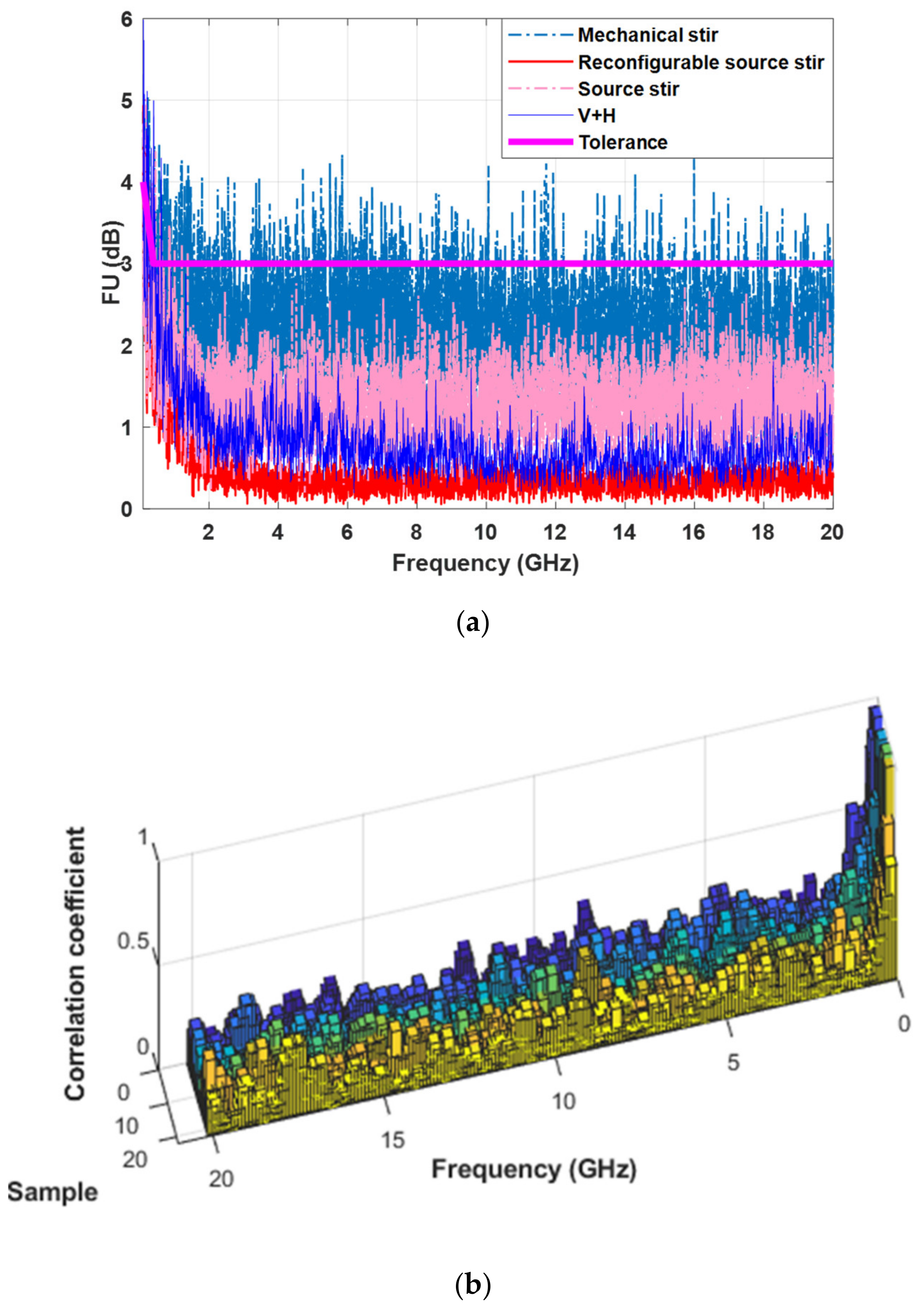
| FU (dB) | 0.3 | 0.8 | 2.5 | 1.5 |
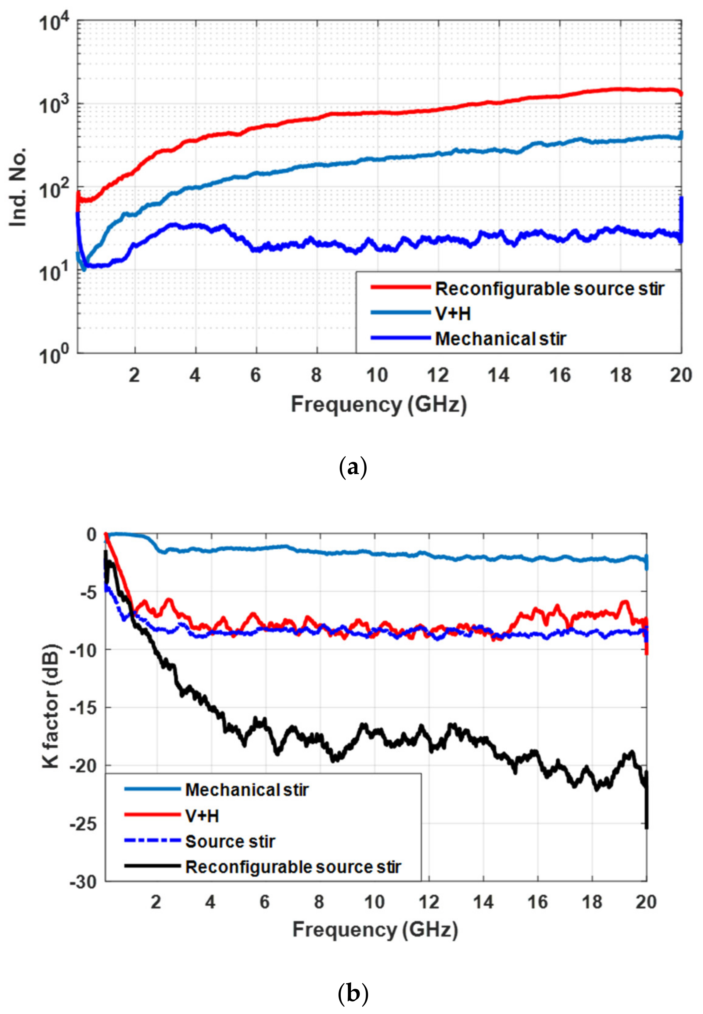
| K-factor (dB) | −17 | −8 | −2 | −8 |
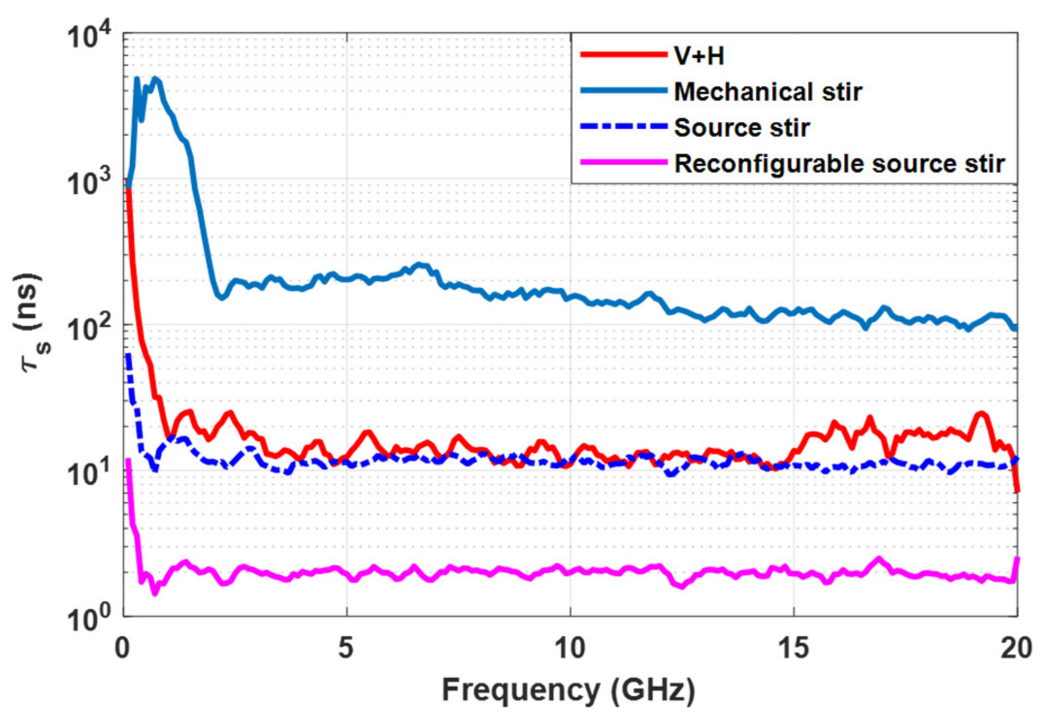
| (ns) | 2 | 12 | 150 | 12 |
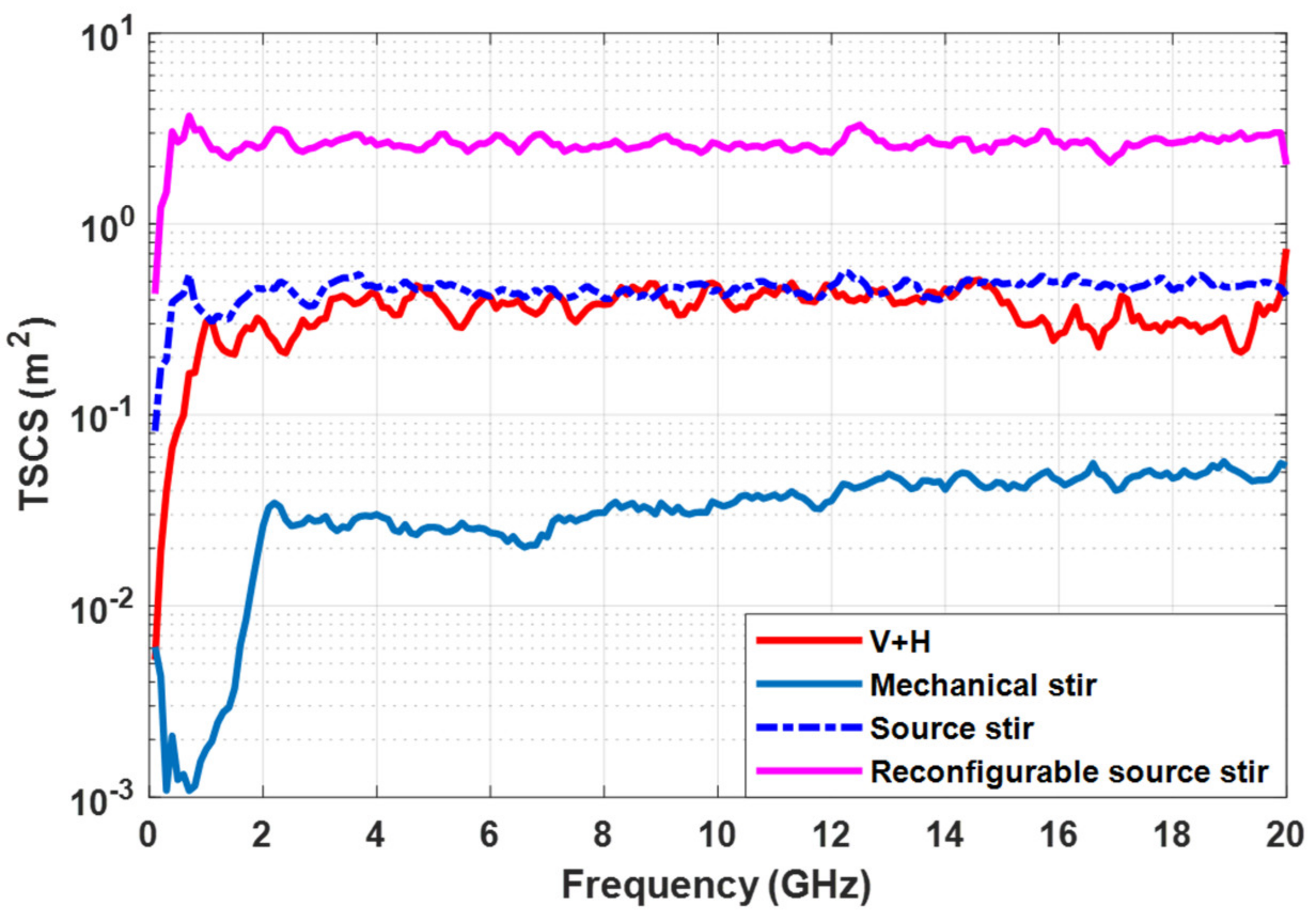
| ) | 2.5 | 0.4 | 0.4 | 0.05 |
Publisher’s Note: MDPI stays neutral with regard to jurisdictional claims in published maps and institutional affiliations. |
© 2022 by the authors. Licensee MDPI, Basel, Switzerland. This article is an open access article distributed under the terms and conditions of the Creative Commons Attribution (CC BY) license (https://creativecommons.org/licenses/by/4.0/).
Share and Cite
Yu, C.; Zhao, Y.; Dai, H.; Qi, W.; Fang, F.; Xia, W.; Xu, Q. Improving the Reverberation Chamber Performance Using a Reconfigurable Source Stirring Antenna Array. Electronics 2022, 11, 1462. https://doi.org/10.3390/electronics11091462
Yu C, Zhao Y, Dai H, Qi W, Fang F, Xia W, Xu Q. Improving the Reverberation Chamber Performance Using a Reconfigurable Source Stirring Antenna Array. Electronics. 2022; 11(9):1462. https://doi.org/10.3390/electronics11091462
Chicago/Turabian StyleYu, Chen, Yongjiu Zhao, Huijuan Dai, Wenjun Qi, Feng Fang, Wenjun Xia, and Qian Xu. 2022. "Improving the Reverberation Chamber Performance Using a Reconfigurable Source Stirring Antenna Array" Electronics 11, no. 9: 1462. https://doi.org/10.3390/electronics11091462
APA StyleYu, C., Zhao, Y., Dai, H., Qi, W., Fang, F., Xia, W., & Xu, Q. (2022). Improving the Reverberation Chamber Performance Using a Reconfigurable Source Stirring Antenna Array. Electronics, 11(9), 1462. https://doi.org/10.3390/electronics11091462