Abstract
As a competitive candidate of orthogonal frequency-division multiplexing (OFDM), filter-bank multicarrier (FBMC) has significant advantages in low spectrum leakage, relaxed synchronization requirements and high spectral efficiency. However, the loss of orthogonality leads to intrinsic interference in FBMC, whereas most methods eliminate it by sacrificing data symbols, resulting in a non-negligible decrease in spectral efficiency. In this context, we propose a new method that eliminates intrinsic interference completely without sacrificing any data symbols thanks to the power multiplexing in the transmitter and the successive interference cancellation scheme in the receiver, contributing to a higher spectral efficiency compared with previous methods. Both the analytical and simulation results demonstrate that the proposed method has higher spectral efficiency and similar power efficiency compared with the traditional coded auxiliary pilot (CAP) method without a notable decrease in bit error rate (BER) performance.
1. Introduction
Multicarrier modulation is a crucial technique that enables high spectral efficiency and robustness to multipath fading. As one of typical multicarrier modulation techniques, orthogonal frequency division multiplexing (OFDM) has been widely used in 5G wireless communication [1]. However, OFDM has serious spectrum leakage, strict synchronization requirements and excessive dependence on cyclic prefixes, being not in line with future mobile communication requirements. As a promising candidate of OFDM, filter-bank multicarrier (FBMC) adopts a well-designed prototype filter to shape subcarriers, reducing spectral sidelobes significantly [2]. Additionally, a well-designed filter bank makes it less sensitive to the frequency offset, which relaxes synchronization requirements. Furthermore, FBMC needs no cyclic prefixes and has a higher spectral efficiency, making it more competitive in future communication systems.
However, unlike the OFDM system, which satisfies the orthogonality in a complex domain, the orthogonality of FBMC is only satisfied in a real domain, resulting in intrinsic interference from FBMC data symbols to pilot symbols [3]. The intrinsic interference is connected with the filter bank adopted and data symbols transmitted but independent of channel states and environmental noise. Unfortunately, it degrades FBMC channel estimation performance seriously because of inaccurate pilot symbols [4]. As a result, the intrinsic interference must be eliminated clearly before channel estimation in the receiver.
Many methods of intrinsic interference cancellation have been proposed, among which the pairs of pilots (POP) method is an effective solution. It assumes that two adjacent moments of the subcarrier have the same channel responses and thus writes out a set of equations about the channel responses at two adjacent pilot locations and then solves the equations to obtain correct channel estimation [5]. However, the estimation result is affected by the noise of pilot pairs. Based on the POP method, the authors in [6] utilized complex-valued symbols as pilot pairs to control the noise effect, whereas the authors in [7] solved it based on a preamble design, but they both led to a higher complexity. Another method named interference approximation method (IAM) adopted the preamble-based structure and estimated intrinsic interference by setting zeros or known symbols around the pilot symbol [8,9]. However, IAM has a heavy pilot burden, which results in low spectral efficiency. An improved method in [10] did not require zeros between pilot symbols and data symbols by utilizing the distribution characteristic of demodulated offset quadrature amplitude modulation (OQAM) symbols, whereas the pilot overhead still needed two columns of OQAM symbols. An iteration method based on IAM did not set zeros around pilots but adopted the idea of an iteration to estimate unknown data symbols with known pilot symbols [11]. After several iterations, ideal estimates could be obtained with the price of a high computational complexity. Other improved iteration methods eliminated intrinsic interference more clearly, but the computation complexity became more unacceptable [12,13,14]. In summary, these methods estimate or eliminate intrinsic interference at the receiver. However, signals at the receiver have more uncertainty compared with signals at the transmitter, whereupon higher complexity is needed to achieve satisfactory results when eliminating intrinsic interference at the receiver.
On the contrary, the interference cancellation method (ICM) eliminates intrinsic interference at the transmitter to reduce receiver burden [15,16]. However, ICM adopts a preamble-based structure where pilot symbols concentrate in the front part of the FBMC symbol, leading to a limited application scenario. In this context, a scattered pilot-based structure is a better choice that inserts pilot symbols into the whole FBMC symbol separately, contributing to a widely used channel estimation. The auxiliary pilot (AP) method was put forward based on the scattered-pilot structure, and it inserted an auxiliary pilot at the location around the pilot symbol to eliminate intrinsic interference completely at the transmitter [17]. However, it is infeasibly greedy for power because the average power overhead of the auxiliary pilot is twice the average power of the data symbol. Another method with a low power cost adopts linear coding means, but intrinsic interference has notable residuals because the coding length cannot be too long [18]. The coded auxiliary pilot (CAP) method can be combined with the AP method and the linear coding method to completely eliminate intrinsic interference with a low power overhead, but it still needs auxiliary pilots [19]. Recently, a method named “frame repetition” eliminated intrinsic interference based on frame repetition, in which QAM symbols are transmitted instead of OQAM symbols [20,21]. It only needed two columns of symbols as the pilot overhead compared with the IAM method, but the frame repetition led to increased sensitivity to the channel coherence time. In summary, these methods put an interference cancellation scheme at the transmitter and thus brought the receiver signal recovery a good condition. However, these methods all eliminate intrinsic interference by sacrificing data symbols named “auxiliary pilots”, resulting in a non-negligible decrease in spectral efficiency, especially in severe channel conditions, which need a high density of pilots. Some other methods need no auxiliary pilot but utilized iterations, but they all have an infeasible computation complexity.
This article proposes a new intrinsic interference cancellation method in the FBMC system without iterations or sacrificing data symbols. In the transmitter, data symbols around pilot symbols are first coded by the power multiplexing matrix, and then, the conventional CAP method is adopted to cancel intrinsic interference completely and to sacrifice a few data symbols. In contrast, these sacrificed data symbols are recovered by our successive interference cancellation scheme in the receiver, which contributes to a higher data rate. The simulation results show that the proposed method has a higher spectral efficiency and similar power efficiency compared with the CAP method, without a notable decrease in BER performance.
The rest of this paper is organized as follows. Section 2 introduces the intrinsic interference of FBMC and the traditional CAP method. In Section 3, the proposed method is explained in detail. Finally, the simulation results and conclusions are given in Section 4 and Section 5, respectively.
The following notations are used in this article. Uppercase and lowercase boldface denote matrices and vectors, respectively. The superscripts and stand for the transpose and conjugate transpose, respectively. means the Euclidean norm of a vector. represents the expectation, and denotes the real parts. is the matrix trace operator, and represents the complex Gaussian probability distribution function.
2. System Model
2.1. Intrinsic Interference of FBMC
We denote the real-valued data symbol corresponding to the th subcarrier of the th FBMC symbol by , which is obtained by taking the real or imaginary parts of the complex QAM symbol. M represents the total number of subcarriers, and denotes the time duration of , which is the impulse response of the PHYDYAS prototype filter [2,22] with an overlapping coefficient equal to 4. Then the FBMC baseband signal transmitted in the time domain, as shown in Figure 1, can be expressed as [23]
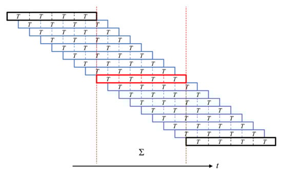
Figure 1.
FBMC signal transmitted in the time domain with the “overlap-add” method. The red frame denotes the FBMC symbol to be received, and the blue frames stand for the FBMC symbols interfering with the red frame.
As shown in Figure 1, the FBMC signal transmitted in the time domain adopts the “overlap-add” method, which can be fully explained by (1). in (1) stands for the th FBMC symbol, which has M subcarriers and a time duration of , corresponding to a colored frame with time delay in Figure 1. means all FBMC symbols overlap with respective time delays and then are added together to produce FBMC signals , i.e., “overlap-add”, corresponding to Figure 1. However, an overlap of several FBMC symbols results in an interference from the other 14 FBMC symbols to the FBMC symbol to be received and previous studies in the literature named it “intrinsic interference”. Fortunately, the intrinsic interference can be eliminated completely in the AWGN channel with “real-orthogonality” expressed as follows [3]
where denotes the Kronecker delta function. We express the received signal as , where denotes the channel impulse response and is the white noise. It is assumed that the time length of the prototype filter is much larger than the maximum delay of the channel, and the channel remains unchanged within the time length of the prototype filter. Then, the received signal is approximately expressed as
where represents the channel frequency response (CFR) of the th subcarrier of the th FBMC symbol. In the receiver, data symbols without considering white noise are recovered by matched filtering, described as follows
where denotes the coefficient of intrinsic interference from the th subcarrier of the th FBMC symbol to the th subcarrier of the th FBMC symbol. As shown in Table 1, the coefficient has a pure imaginary value.

Table 1.
The value of coefficient of intrinsic interference corresponding to the th subcarrier of the th FBMC symbol to the th subcarrier of the th FBMC symbol [23].
Assuming that channel changes in adjacent time-frequency points are not obvious and, thus, CFR of the time-frequency point near the time–frequency point meets the requirement , Equation (4) can be simplified as
where pure imaginary valued is the “intrinsic interference” to the pure real valued symbol . The intrinsic interference must be eliminated before channel estimation, and then, the receiver can recover symbol from correctly with a correct estimate of .
2.2. Coded Auxiliary Pilots (CAP) Method for Intrinsic Interference Cancellation
In order to make correct channel estimations, many methods are proposed to eliminate intrinsic interference to pilot symbols, among which the CAP method in literature [19] is a good solution. However, it eliminates intrinsic interference completely with sacrificing data symbols, resulting in a decrease of spectral efficiency. Based on CAP method, we propose a new method which has a higher spectral efficiency, whereas an introduction of CAP is necessary before our study. Details of CAP method are as follows.
Denote OQAM data symbols around the pilot by and represent the coded symbols as , which is obtained by , where is a coding matrix of size and is a vector waiting to be solved. Denote coefficients of intrinsic interference in Table 1 by , and the interference generated by the surrounding data symbols to the pilot can be expressed as
where , and . Supposing that the coding matrix satisfies the equation , (6) is then simplified as , where must be equal to zero in order to eliminate intrinsic interference. Under these equality constraints, the vector can be calculated as
Pilot symbols are no longer subjected to intrinsic interference after the coding operations described above, and the receiver can estimate channels correctly based on these pilot symbols. It is assumed that the channel is perfectly estimated, and vector is an estimate of after equalization in the receiver. Supposing the coding matrix satisfies the equation , then the estimate of can be calculated by at the receiver. Note that the coding matrix satisfying both and can be constructed based on [19], and the case for used in this article is given directly as follows:
3. Description of the Proposed Scheme
The CAP method described in Section 2 eliminates intrinsic interference by sacrificing data symbols around pilot symbols, resulting in a decrease in spectral efficiency, especially in the high pilot density case. In this section, a new scheme is proposed to eliminate intrinsic interference without sacrificing any data symbols by applying power multiplexing coding in the transmitter and successive interference cancellation in the receiver. Details of the proposed method are introduced in the following.
3.1. Power Multiplexing and Intrinsic Interference Cancellation in Transmitter
Denote OQAM symbols around the pilot by vector and represent coded symbols as , which are obtained by
where is a power multiplexing coding matrix of size , which is calculated by
where c is a real-valued coefficient satisfying the inequality and is a power normalization factor that satisfies . It is observed that each element in is a weighted sum of and another element in , and weight coefficients in stand for the power multiplexing strategy of for transmitting these elements in . Note that K represents the number of power multiplexed symbols and c stands for the power multiplexing level. It is obvious that and is regarded as additive noise when we want to recover from in the receiver. This indicates that a small value of c is beneficial to the recovery of from for but makes the recovery of from for more difficult. Therefore, the parameter c is of great importance, and it has to make a trade-off, as we will discuss in Section 4. In order to eliminate intrinsic interference, we denote N elements of by vector , () and then code in following way:
where is a coded vector, is a vector waiting to be solved, and is a coding matrix of size that satisfies the following equations:
where matrix is described in (8), is a zero vector of size , is a unit vector of size , and is a power normalization factor that satisfies . The intrinsic interference from data symbols to the pilot can be expressed as
Substitute in (15) with (12), and then, let the intrinsic interference equal to zero. Under these equality constraints, we calculate by
Up to this point, the intrinsic interference to pilot symbols is eliminated completely, and we sacrifice no data symbols thanks to the power multiplexing coding process in the transmitter.
3.2. Successive Interference Cancellation in Receiver
In the receiver, it is assumed that perfect channel estimation is conducted with the help of pilot symbols. Note that this assumption is reasonable because intrinsic interference has been eliminated clearly and practical channel estimation has a very small gap with the perfect one, as we demonstrate in Section 4. Although there has been no intrinsic interference anymore at the receiver, we need to recover data symbols with the interference results from power multiplexing. Fortunately, successive interference cancellation (SIC) is a good algorithm for this, as we will describe in detail next.
The estimate of after equalization can be expressed as , where stands for the estimate of and is a vector of independent and identically distributed (i.i.d.) noise. The estimate of is calculated by
where , , is an estimate of , and it is easy to know that according to (9) and (18).
The successive interference cancellation algorithm described in Figure 2 is used to recover from . The first step of this algorithm regards as additive noise to and adopts detection algorithms to recover from for . It is meaningful to note that the maximum likelihood (ML) detection algorithm is a good choice in this situation. It is known that M points in a constellation diagram need to be compared if we choose M-order quadrature amplitude modulation (QAM) in traditional multicarrier communication systems, such as OFDM. Fortunately, the ML detection algorithm only needs to compare points for M-order QAM in FBMC because data symbols in FBMC are real-valued symbols extracted from real or imaginary parts of complex QAM symbols. The difference between OFDM and FBMC in an M-order QAM constellation diagram is described in Figure 3.
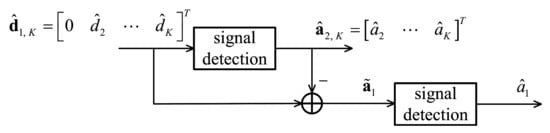
Figure 2.
Successive interference cancellation algorithm.
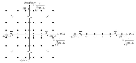
Figure 3.
Constellation diagrams of M-order QAM in OFDM (left) and FBMC (right).
Supposing that is perfectly recovered from , as shown in Figure 2 for , i.e., , the next step of successive interference cancellation algorithm is to recover from and for . We represent as follows:
and the estimate of is calculated by the following step:
where is a unit vector of size , and is a noise of . It is obvious that increasing the values of c and K is beneficial to the signal-to-noise ratio (SNR) of , but it also means more inaccurate signal detection results of and higher computational complexity. As a result, the values of c and K should be assigned properly to achieve a compromise among these factors. Note that data symbol was sacrificed in the transmitter for intrinsic interference cancellation, but fortunately, we recovered in (20) with the help of power multiplexing coding in the transmitter and successive interference cancellation in the receiver, contributing to an increase in spectral efficiency compared with previous methods.
3.3. Computation of Spectral Efficiency
Supposing that FBMC symbols are transmitted in a frame that contains data symbols and pilot symbols, we denote time duration and frequency bandwidth of the frame by and , respectively. Note that the information quantity of a data symbol in M-order QAM is bits because the data symbols in FBMC are real-valued symbols extracted from real or imaginary parts of complex QAM symbols. Then, the spectral efficiency can be calculated by
It is obvious that in the proposed method is larger than that in the CAP method because of a smaller in the former, whereupon the proposed method has a higher spectral efficiency compared with previous methods.
3.4. Power Penalty for Intrinsic Interference Cancellation
The total power of transmitted in the CAP method is calculated by
where is the power of a transmitted vector that contains data symbols and described in (6) is the power penalty for intrinsic interference cancellation.
Similarly, the total power of in (12), which is transmitted in the proposed method, is calculated by
where is the power of the transmitted vector that contains N data symbols, and described in (16) is the power penalty for intrinsic interference cancellation. It is obvious that and have very close values; hence, the proposed method and the CAP method have similar power penalties for intrinsic interference cancellation.
4. Numerical Results
The parameters in our simulations are as follows. The number of subcarriers of FBMC is , the filter bank adopted is the PHYDYAS filter [2,22], with an overlapping coefficient equal to 4. The frame structure is shown in Figure 4, where each frame is composed of 14 FBMC symbols, and a pilot is inserted into the seventh FBMC symbol per four subcarriers. The SUI-3 channel proposed by IEEE 802.16 is adopted [24], and channels of different frames are quasi-static. We adopt the suggestions in [25] and set the energy of each pilot symbol to twice the energy of the complex QAM symbol. We use the least squares (LS) algorithm to estimate channel response at pilot positions and then conduct a linear interpolation among them to obtain a channel response of the full data frame.
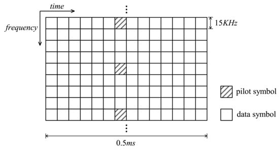
Figure 4.
Frame structure adopted in simulations.
It is known that a subframe duration that contains 14 OFDM symbols is 1 ms in LTE [26]. We adopt a similar frame structure in our simulations, but each subframe duration is equal to 0.5 ms, as shown in Figure 4. The reason for this can be explained in Figure 1: the duration of an FBMC symbol is , and we overlap and add several FBMC symbols to produce signals transmitted in the time domain. In the receiver, we obtain a full FBMC symbol every duration thanks to the “overlap-add” method in the transmitter, whereupon we assign a subframe duration in our simulation that is half of that in LTE. Note that although FBMC has a higher symbol-receiving rate compared with OFDM, FBMC symbols only carry half information (real or imaginary parts) of complex QAM symbols. As a result, FBMC and OFDM have same spectral efficiency when everything else is the same. Note that the proposed method can be used in the 5G frame structure without modification because of the similar basic frame structures of 5G and LTE, but we chose LTE structure for easy understanding.
4.1. Spectral Efficiency Performance
As shown in Figure 5, the proposed method has a higher spectral efficiency compared with the CAP method, and the gap is becoming wider with the increase in pilot density. The reasons for this can be explained as follows. In the proposed method, data symbols around pilot symbols were first coded by the power multiplexing matrix in the transmitter, and then, the conventional CAP method was adopted to cancel intrinsic interference completely by sacrificing a few data symbols, whereas these sacrificed data symbols were recovered by the successive interference cancellation scheme in the receiver, contributing to a higher spectral efficiency compared with previous methods. Note that it is obvious that the proposed method has a higher computational complexity because of two additional processes, i.e., power multiplexing and successive interference cancellation, but it is meaningful to harvest spectral efficiency improvements.
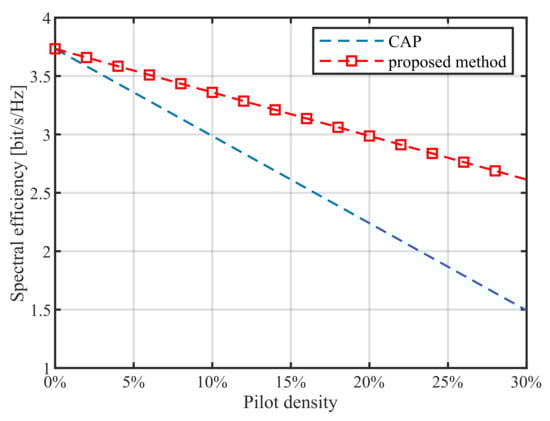
Figure 5.
Spectral efficiency when the 16QAM and frame structures in Figure 4 are adopted.
4.2. BER Performance
Simulation results of BER are shown in Figure 6 and Figure 7 when the parameter N in (8) and (12) is equal to 4 and 16QAM is adopted. The proposed methods of different coefficient values have similar BER performances and negligible decreases compared with the CAP method. The decrease in BER performance compared with the CAP method mainly results from power multiplexing and the successive interference cancellation algorithm we adopted to recover the sacrificed data symbols for intrinsic interference cancellation. As shown in Figure 8, it is understandable that the MSE curves of the CAP and proposed methods are overlapped because their BER performance gap is very small, whereas we add Figure 8 for its wide use in similar studies.
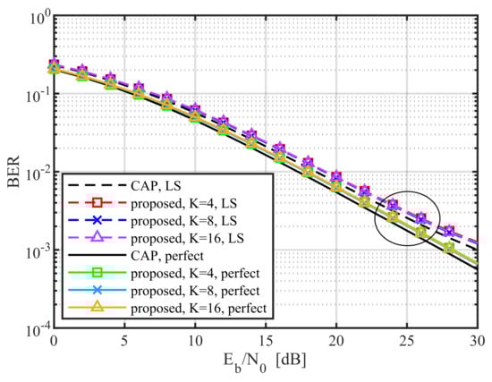
Figure 6.
BER performances when the LS channel estimation method is adopted (broken line) and when channel state information is known perfectly (solid line). Note that is adopted in simulations.
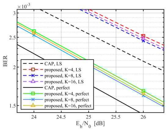
Figure 7.
Zoomed-in version of a portion of Figure 6.
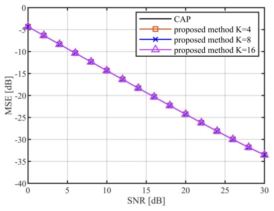
Figure 8.
MSE performances when the LS channel estimation method is adopted.
The variation in c has an opposite influence on and about SNR, whereas they both influence the overall BER performance. Similarly, the increase in K benefits the SNR of but results in more coded symbols in (9), which interfered due to . The values of c and K contributing to the optimal overall BER performance are difficult to be determined in theory, but fortunately, suboptimal values also work well. As shown in Figure 9, we selected a few values of c and K to simulate BER performance at dB, and it is easy to find that the optimal value of c is around 0.15 and that different values of K have similar BER performances when . Note that the other has a similar selection process of suboptimal c, and Figure 10 illustrates the suboptimal c corresponding to different values of . These suboptimal values are easy to find after a few attempts, and they are close to the optimal one, which means that there is no need for complex calculations for the optimal value.
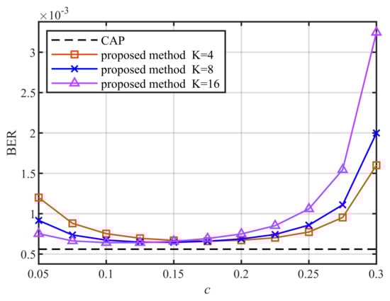
Figure 9.
BER performance when channel state information is known perfectly and dB. Note that K represents the number of power multiplexed symbols and c stands for the power multiplexing level.
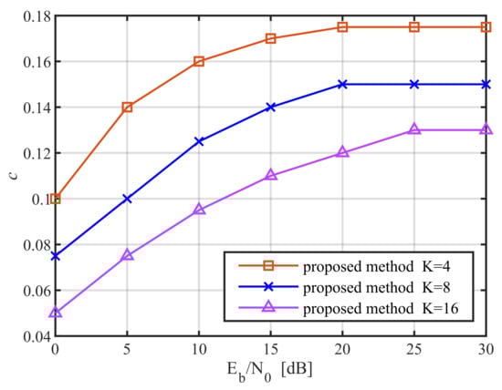
Figure 10.
The values of c when the suboptimal BER performance is obtained.
5. Conclusions
This article proposed a new method that eliminates intrinsic interference to pilot symbols of FBMC without iterations or sacrificing data symbols. Thanks to the power multiplexing in the transmitter and successive interference cancellation schemes in the receiver, the proposed method has a higher spectral efficiency compared with previous methods. We used numerical results to prove that the proposed method has a similar power penalty for intrinsic interference cancellation compared with the CAP method. The simulation results show that suboptimal results have similar BER performances compared with the optimal one, and they are all without a notable decrease in BER performance compared with the CAP method. Note that both the CAP and proposed methods need improvements in PAPR performance, and many studies about the PAPR reduction in FBMC have been proposed but further research is still needed [27,28].
Author Contributions
Conceptualization, J.L.; methodology, J.L., S.L. and H.D.; software, J.L., S.L. and H.D.; validation, J.L., S.L., H.D. and Z.L.; formal analysis, J.L. and Z.L.; investigation, J.L.; resources, J.L. and Z.L.; data curation, J.L.; writing—original draft preparation, J.L.; writing—review and editing, S.L., H.D. and Z.L.; visualization, S.L.; supervision, Z.L.; project administration, Z.L.; funding acquisition, Z.L. All authors have read and agreed to the published version of the manuscript.
Funding
This research received no external funding.
Institutional Review Board Statement
Not applicable.
Informed Consent Statement
Not applicable.
Data Availability Statement
Not applicable.
Conflicts of Interest
The authors declare no conflict of interest.
References
- Li, L.; Chen, X.; Xue, L.; Hu, D.; Zhang, Z. Improved Interference Cancellation Method in FBMC/OQAM system on PAPR reduction. In Proceedings of the 2021 IEEE International Conference on Computer Science, Electronic Information Engineering and Intelligent Control Technology (CEI), Fuzhou, China, 24–26 September 2021; pp. 790–794. [Google Scholar]
- Bellanger, M.; Le Ruyet, D.; Roviras, D.; Terré, M.; Nossek, J.; Baltar, L.; Bai, Q.; Waldhauser, D.; Renfors, M.; Ihalainen, T.; et al. FBMC physical layer: A primer. PHYDYAS January 2010, 25, 7–10. [Google Scholar]
- Siohan, P.; Siclet, C.; Lacaille, N. Analysis and design of OFDM/OQAM systems based on filterbank theory. IEEE Trans. Signal Process. 2002, 50, 1170–1183. [Google Scholar] [CrossRef] [Green Version]
- Chen, D.; Wang, R.; Mei, Y.; Jiang, T. Distribution Line Fitting-Based Channel Estimation Without Guard Symbols for OQAM/FBMC Systems. IEEE Trans. Wirel. Commun. 2021, 20, 3659–3669. [Google Scholar] [CrossRef]
- Lélé, C.; Javaudin, J.P.; Legouable, R.; Skrzypczak, A.; Siohan, P. Channel estimation methods for preamble-based OFDM/OQAM modulations. Eur. Trans. Telecommun. 2008, 19, 741–750. [Google Scholar] [CrossRef]
- Liu, W.; Schwarz, S.; Rupp, M.; Jiang, T. Pairs of Pilots Design for Preamble-Based Channel Estimation in OQAM/FBMC Systems. IEEE Wirel. Commun. Lett. 2020, 10, 488–492. [Google Scholar] [CrossRef]
- Nisar, M.D.; Anjum, W.; Junaid, F. Preamble design for improved noise suppression in FBMC-OQAM channel estimation. IEEE Wirel. Commun. Lett. 2020, 9, 1471–1475. [Google Scholar] [CrossRef]
- Lele, C.; Siohan, P.; Legouable, R. 2 dB better than CP-OFDM with OFDM/OQAM for preamble-based channel estimation. In Proceedings of the 2008 IEEE International Conference on Communications, Beijing, China, 19–23 May 2008; pp. 1302–1306. [Google Scholar]
- Du, J.; Signell, S. Novel preamble-based channel estimation for OFDM/OQAM systems. In Proceedings of the 2009 IEEE International Conference on Communications, Dresden, Germany, 14–18 June 2009; pp. 1–6. [Google Scholar]
- Chen, D.; Wang, R.; Jiang, T. Channel Estimation and Pilot Symbol Optimization Based on Intrinsic Interference Utilization for OQAM/FBMC Systems. IEEE Trans. Signal Process. 2021, 69, 4595–4606. [Google Scholar] [CrossRef]
- Hu, S.; Wu, G.; Li, S. Preamble Design and Iterative Channel Estimation for OFDM/Offset QAM System. J. Netw. 2009, 4, 1050–1057. [Google Scholar] [CrossRef] [Green Version]
- Mahama, S.; Harbi, Y.J.; Burr, A.G.; Grace, D. Iterative interference cancellation in FBMC-QAM systems. In Proceedings of the 2019 IEEE Wireless Communications and Networking Conference (WCNC), Marrakesh, Morocco, 15–18 April 2019; pp. 1–5. [Google Scholar]
- Zhang, J.; Hu, S.; Liu, Z.; Wang, P.; Xiao, P.; Gao, Y. Real-valued orthogonal sequences for iterative channel estimation in MIMO-FBMC systems. IEEE Access 2019, 7, 68742–68751. [Google Scholar] [CrossRef]
- Liu, W.; Chen, D.; Schwarz, S.; Rupp, M.; Jiang, T. Preamble power optimization based on intrinsic interference utilization for OQAM/FBMC channel estimation. IEEE Trans. Veh. Technol. 2020, 69, 13556–13566. [Google Scholar] [CrossRef]
- Kang, S.; Chang, K. A novel channel estimation scheme for OFDM/OQAM-IOTA system. ETRI J. 2007, 29, 430–436. [Google Scholar] [CrossRef]
- Kong, D.; Qu, D.; Jiang, T. Time domain channel estimation for OQAM-OFDM systems: Algorithms and performance bounds. IEEE Trans. Signal Process. 2013, 62, 322–330. [Google Scholar] [CrossRef]
- Javaudin, J.P.; Lacroix, D.; Rouxel, A. Pilot-aided channel estimation for OFDM/OQAM. In Proceedings of the 57th IEEE Semiannual Vehicular Technology Conference, 2003, VTC 2003-Spring, Jeju, Korea, 22–25 April 2003; Volume 3, pp. 1581–1585. [Google Scholar]
- Lele, C.; Legouable, R.; Siohan, P. Channel estimation with scattered pilots in OFDM/OQAM. In Proceedings of the 2008 IEEE 9th Workshop on Signal Processing Advances in Wireless Communications, Recife, Brazil, 6–9 July 2008; pp. 286–290. [Google Scholar]
- Cui, W.; Qu, D.; Jiang, T.; Farhang-Boroujeny, B. Coded auxiliary pilots for channel estimation in FBMC-OQAM systems. IEEE Trans. Veh. Technol. 2015, 65, 2936–2946. [Google Scholar] [CrossRef]
- Kong, D.; Li, J.; Luo, K.; Jiang, T. Reducing pilot overhead: Channel estimation with symbol repetition in MIMO-FBMC systems. IEEE Trans. Commun. 2020, 68, 7634–7646. [Google Scholar] [CrossRef]
- Kong, D.; Zheng, X.; Zhang, Y.; Jiang, T. Frame repetition: A solution to imaginary interference cancellation in FBMC/OQAM systems. IEEE Trans. Signal Process. 2020, 68, 1259–1273. [Google Scholar] [CrossRef]
- Bellanger, M.G. Specification and design of a prototype filter for filter bank based multicarrier transmission. In Proceedings of the 2001 IEEE International Conference on Acoustics, Speech, and Signal Processing. Proceedings (Cat. No. 01CH37221), Salt Lake City, UT, USA, 7–11 May 2001; Volume 4, pp. 2417–2420. [Google Scholar]
- Choi, J.M.; Oh, Y.; Lee, H.; Seo, J.S. Pilot-aided channel estimation utilizing intrinsic interference for FBMC/OQAM systems. IEEE Trans. Broadcast. 2017, 63, 644–655. [Google Scholar] [CrossRef]
- Hari, K.; Baum, D.; Rustako, A.; Roman, R.; Trinkwon, D. Channel Models for Fixed Wireless Applications; IEEE 802.16 Broadband wireless access working group; IEEE: Piscataway, NJ, USA, 2003. [Google Scholar]
- Fazel, K.; Kaiser, S. Multi-Carrier and Spread Spectrum Systems: From OFDM and MC-CDMA to LTE and WiMAX; John Wiley & Sons: Hoboken, NJ, USA, 2008. [Google Scholar]
- Channels, P. Modulation (3GPP TS 36.211 version 10.4. 0 Release 10). ETSI TS 2012, 136, v10. [Google Scholar]
- Na, D.; Choi, K. PAPR reduction scheme for FBMC-OQAM without side information. In Proceedings of the ICC 2019-2019 IEEE International Conference on Communications (ICC), Shanghai, China, 20–24 May 2019; pp. 1–6. [Google Scholar]
- Cheng, X.; Liu, D.; Shi, W.; Zhao, Y.; Li, Y.; Kong, D. A novel conversion vector-based low-complexity SLM scheme for PAPR reduction in FBMC/OQAM systems. IEEE Trans. Broadcast. 2020, 66, 656–666. [Google Scholar] [CrossRef]
Publisher’s Note: MDPI stays neutral with regard to jurisdictional claims in published maps and institutional affiliations. |
© 2022 by the authors. Licensee MDPI, Basel, Switzerland. This article is an open access article distributed under the terms and conditions of the Creative Commons Attribution (CC BY) license (https://creativecommons.org/licenses/by/4.0/).