Article

Study on Static Characteristics of Ultra-Precision Aerostatic Motorized Spindle under Gas–Magnetic Field Coupling

1
Faculty of Mechanical and Electrical Engineering, Kunming University of Science and Technology, Kunming 650500, China
2
School of Mechatronics Engineering, Zhongyuan University of Technology, Zhengzhou 451191, China
*
Author to whom correspondence should be addressed.
Electronics 2022, 11(9), 1434; https://doi.org/10.3390/electronics11091434
Submission received: 4 April 2022 / Revised: 25 April 2022 / Accepted: 28 April 2022 / Published: 29 April 2022
(This article belongs to the Special Issue Mechatronic Control Engineering)

Abstract

:
In the working process of ultra-precision aerostatic motorized spindles, the journal and the rotor must have a certain eccentricity to have a certain bearing capacity and stiffness, which will induce the unbalanced magnetic pull (UMP). The intercoupling of the UMP and the gas film force will affect the motion state of the rotor and the accuracy of spindles. In order to deeply study the influence of the UMP caused by the rotor eccentricity on the equilibrium position of aerostatic spindles, a physical model of an aerostatic spindle based on slit throttling gas bearing is established and the coupling effect between the rotor and the motor rotor is studied and analyzed as a whole. The equilibrium position of the rotor under the combined action of gravity, the gas film force and the UMP is deduced, and a gas–magnetic field coupling calculation program based on the finite difference method is proposed. The calculation results show that with the increase in rotational speed, the equilibrium position of the rotor will move to the center of the journal in the micron scale, and the moving amplitude will gradually slow down. The UMP caused by rotor eccentricity can offset the rotor equilibrium position in nanometer scale, and the influence degree decreases sharply as the rotor moves to the journal center. With the increase in rotational speed, the direct stiffness and the cross stiffness will increase, and the amplitude of the cross stiffness is greater than the direct stiffness. This study is of great significance for further studying the influence of the rotor eccentricity on the equilibrium position and the accuracy of the rotor.

1. Introduction

Compared with traditional ball bearings, aerostatic bearings have the characteristics of low friction, high rotational speed and high precision [1], and are widely used in the field of precision and ultra-precision machining [2]. With the increasing accuracy requirements of ultra-precision machine tools, such as the Moore Nanotech 250UPL ultra-precision single-point diamond lathe, whose spindle run-out is less than 12.5 nm in the full speed range (50–10,000 rpm) [3], various factors affecting the spindle rotation accuracy should be fully considered in the design [4]. According to the working principle of aerostatic journal bearings, the journal and the rotor must have a certain eccentricity to have the capacity and the stiffness required. However, when the motor rotor and the motor stator have a certain eccentricity, it will lead to an uneven magnetic gap and unbalanced magnetic pull (UMP). Under the action of the UMP, the eccentricity of the rotor continues to increase; the decrease in the gas film leads to an increase in the compressed gas film force. The coupling between the UMP and the gas film force will lead the rotor reach a new equilibrium position. According to the types of the UMP, it can be divided into two types: static eccentricity and dynamic eccentricity. The static eccentricity includes the eccentricity of the motor rotor caused by rotor eccentricity, and the eccentricity of the motor stator and the journal caused by assembling errors; the dynamic eccentricity refers to the eccentricity of the rotor and the motor rotor caused by assembling errors. The UMP caused by the static eccentricity can be regarded as a constant value only related to eccentricity, and the direction points to the minimum magnetic gap along the motor rotor deviation angle. The magnitude and direction of the UMP caused by the dynamic eccentricity vary with the rotor’s rotation. Many scholars have studied the UMP. Kim et al. [5] developed an analytical technique for predicting the instantaneous magnetic field distribution in the gas gap region of permanent magnet motors with rotor eccentricity. Chong et al. [6] presented a new method to calculate the UMP in cage induction motors, considering the curved dynamic eccentricity. Li et al. [7] introduced a new analytical model suitable for studying the relationship between the eccentricity effect and design parameters of slotted permanent magnet motors. Dorrell et al. [8] reported on an investigation into the UMP in permanent-magnet motors due to either magnetic asymmetry or static rotor eccentricity. Based on the Jeffcott rotor model, Xiang et al. [9] analyzed the stiffness characteristics of the rotor system of the permanent magnet synchronous motors (PMSM) and investigated the nonlinear dynamic behaviors influenced by the UMP. Kim et al. [10] discussed magnetic force imbalance and cogging torque in permanent-magnet motors under both static and dynamic rotor eccentricity. Kim et al. [11] presented entirely analytical models for the radial forces resulting from the eccentricity in a toroidally wound brushless DC motor by applying the perturbation theory and obtained the gas-gap magnetic field with eccentricity. Zhang et al. [12] obtained the magnetic field distributions of corresponding domains in the motor with rotor eccentricity by superposing the first-order component of the magnetic field onto the zeroth-order component according to the perturbation theory. Han et al. [13] proposed a magnetic equivalent circuit modeling method to calculate both the radial and tangential motor eccentric force. Kim et al. [14] presented an optimal method for the rotordynamic simulation of induction motors, including the effects of UMP. Guo et al. [15] analyzed the vibration of a model rotor in a three-phase generator under the action of the UMP and the eccentric force by the numerical method and harmonic analysis. Liu et al. [16] investigated the nonlinear oscillations of a PMSM based on a Jeffcott rotor-bearing system, and the effects of the UMP, nonlinear restoring forces due to the Hertz contact force and bearing clearance, rotor weight and rotor mass eccentricity were considered. Gustavsson et al. [17] studied the influence of nonlinear magnetic pull for a hydropower generator where the generator spider hub does not coincide with the center of the generator rim by introducing a nonlinear model of UMP to the model. Zhao et al. [18] established the nonlinear dynamic equation of a rub-impact rotor-bearing system under UMP by using the Lagrange equation. Zhang et al. [19] installed a 10 kg workpiece fixture on the rotor to produce eccentricity and vibration, so as to study the influence of UMP on the machined surface quality. Based on Isight software, Gao et al. [20] developed an integrated multiphysics simulation platform with application to micromilling machines. However, there are few studies on the equilibrium position of the rotor and the coupling between the UMP and the gas film force. At the same time, since the UMP is very small under normal cutting conditions and its influence cannot be accurately detected, the research on UMP was mainly carried out in the following aspects: one type of research is to estimate the UMP or seek a method to reduce the UMP. The other is to establish the rotor dynamics equation considering unbalanced magnetic pull and obtain the rotor motion trajectory. However, in practice, the stiffness and damping change nonlinearly with the change in the rotor’s position, and the fixed value method will lead to errors.
As the aerostatic motorized spindle can reach extremely high speeds, it has been widely used in high-speed machining, which calls for a continual increase in removal rates, both to permit the use of smaller drill bits and to reduce the processing times involved in milling and grinding [21]. However, for ultra-precision machining, regarding the spindle speed, higher may not be better. On the one hand, it is limited by the motor power; on the other hand, the purpose of ultra-precision machining is to fabricate high-precision components with nanometric surface roughness and with sub-micrometric form errors [22]. Cutting conditions [23] such as tool geometry, cutting depth and feed rate; material properties [24,25,26] such as material swelling and recovery; crystal orientation; and spindle vibration [27,28] induced by unbalanced mass and eccentric moments will have a significant impact on the surface processing quality of the components. For example, in ultra-precision turning, with the increase in spindle speed, the surface roughness decreases, but when the spindle speed increases to a certain value, the surface roughness tends to increase. Therefore, the working speed of many ultra-precision machining machines is below a critical value to reduce the impact of spindle vibration. When the rotor speed is below a critical speed, its flexural deformation can be ignored and it can be considered as a rigid rotor; at this time, the rotor will undergo reciprocating vibration at its equilibrium position under the action of unbalanced force and force coupling. The offset of the equilibrium position will inevitably lead to the offset of the rotor’s trajectory. For precision machine tools, the error caused by the offset of the equilibrium position cannot be ignored. In order to accurately study the influence of the UMP caused by static eccentricity on the rotor, in this paper, we assume that the rotor is a homogeneous rigid rotor and is concentric with the rotor of the motor, the unbalanced centrifugal force can be ignored and its working speed is below a critical speed. This paper introduces a method to study an aerostatic motorized spindle’s static characteristics by taking the slit throttling aerostatic bearing as the research object; the Reynolds equation of compressible gas lubrication is established by using the finite difference method to obtain the pressure distribution, and then the bearing capacity is obtained. Finally, according to the force balance equation, the equilibrium position of the rotor is obtained.

2. Mathematical Models

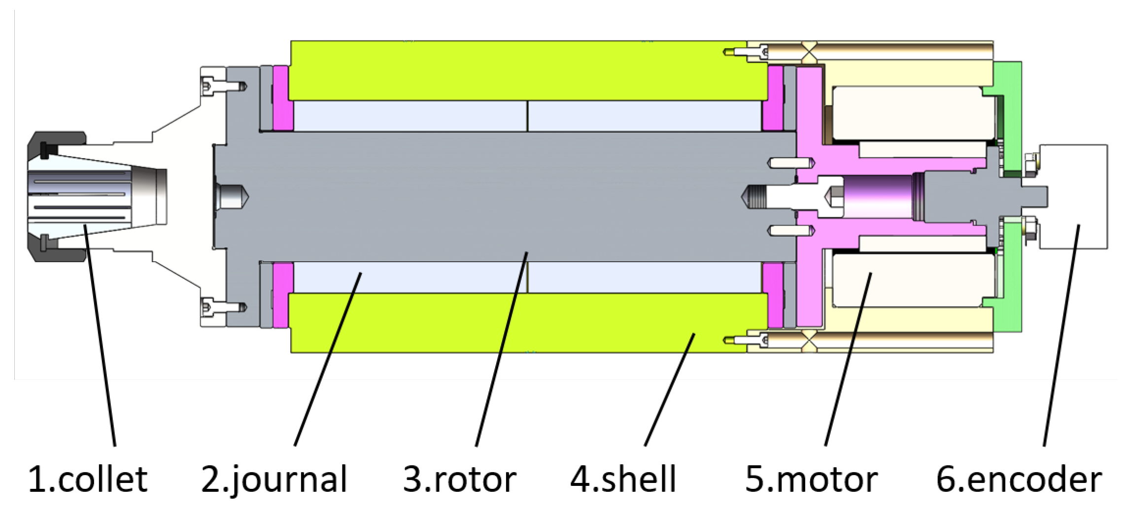
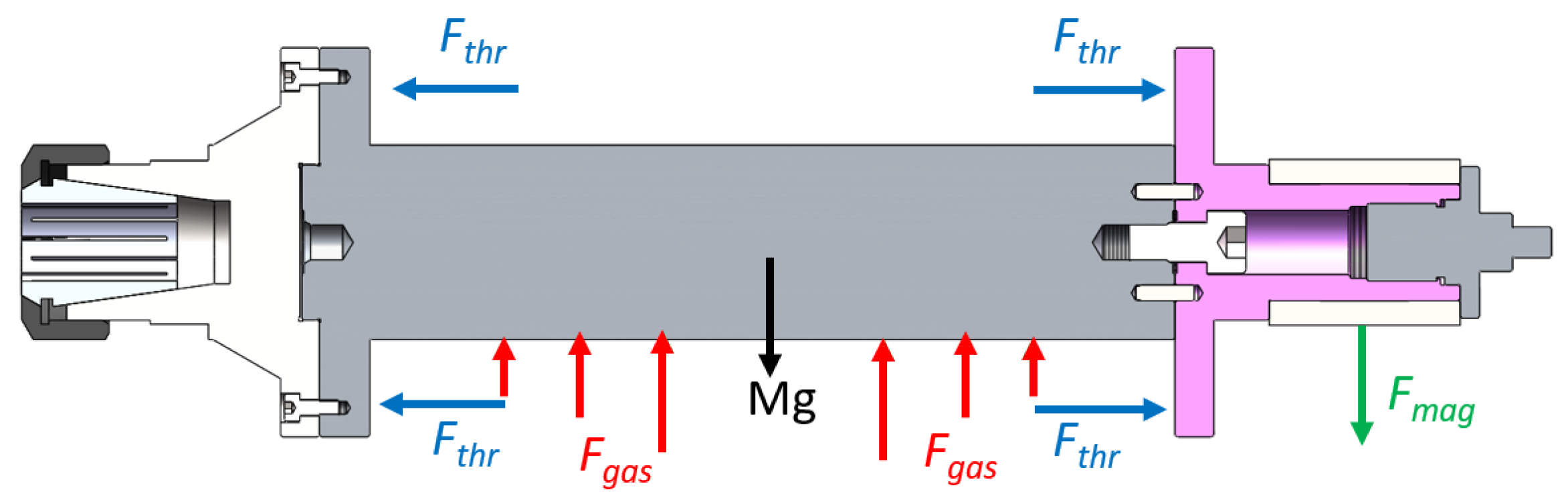
2.1. Physical Model Structure

The mechanical parts consist of a gas bearing (journal and rotor), motor (motor stator and motor rotor), shell and gas supply system, shown in Figure 1. The forces on the rotor during operation can be divided into gravity M g , radial gas film force F g a s , axial thrust force F t h r and UMP F m a g , as shown in Figure 2. Structural parameters of the motorized spindle are given in Table 1.

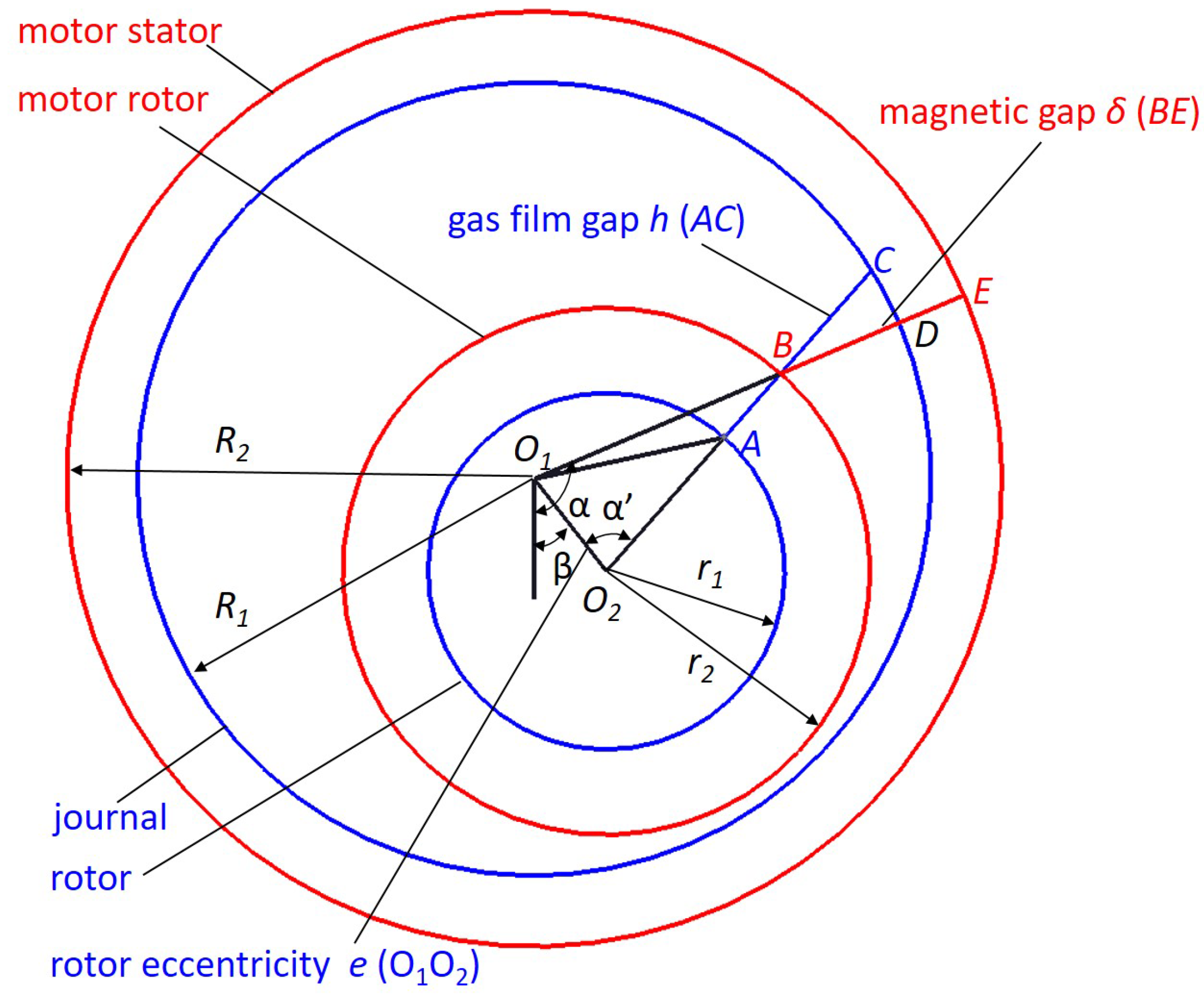
2.2. Simplified Error Estimation of Gas Film Gap and Magnetic Gap

For convenience of analysis, blue lines represent the diameters of the rotor and the journal and red lines represent the motor’s rotor and stator. Taking a point of the rotor A as an example, the gas film force points to O 2 along the direction of O 2 A , A C is the gas film gap, and the UMP points to E along the direction of O 1 B , B E for the magnetic gap. R 1 for the journal radius, r 1 for the rotor radius, R 2 for the motor stator radius, r 2 for the motor rotor radius, O 1 O 2 for the rotor eccentricity expressed as e, L 1 for the journal length, L 2 for the motor rotor length. The gas film gap and magnetic gap are given in Figure 3.
The gas film gap can be expressed as:
h = R 1 2 e 2 sin 2 α + e cos α r 1
The magnetic gap can be expressed as:
δ = O 1 E O 1 B = R 2 e cos α β + r 2 2 e 2 sin 2 α β
The relationship between α and α β is:
sin α = e cos α β + r 2 2 e 2 sin 2 α β sin α β r 2
It can be seen that the UMP caused by the rotor eccentricity is at the center of the motor stator and points to the minimum gas gap; the resultant force of the gas film force is located in the center of the rotor; the UMP and the gas film force are not on the same vertical plane. The force couple generated by the UMP is balanced by the motor, which can be ignored when studying the equilibrium position. Compared with the rotor radius and motor rotor radius, the rotor eccentricity is very small; for convenience of calculation, the gas film gap and magnetic gap are often simplified and approximately considered as e 2 0 . However, the simplified error is rarely estimated. In order to ensure the accuracy of the calculation, it is necessary to estimate the error. The gas film gap simplification error I 1 and magnetic gap simplification error I 2 can be expressed, respectively, as:
I 1 = 0 2 π R 1 2 e 2 sin 2 α + e cos α r 1 R 1 r 1 + e cos α R 1 2 e 2 sin 2 α + e cos α r 1 d α
I 2 = 0 2 π R 2 e cos α β + r 2 2 e 2 sin 2 α β R 2 r 2 e cos α β R 2 e cos α β + r 2 2 e 2 sin 2 α β d α
When the rotor eccentricity e = 0 , there is no simplification error, I 1 = 0 and I 2 = 0 . When the rotor eccentricity takes the maximum value, the maximum values of errors are obtained by the Simpson formula. Assuming e = 0.02 mm, I 1 = 5 × 10 5 and I 2 = 8 × 10 6 . The error caused by the simplification of the two is very small, so the simplification of the gas film gap and magnetic gap is feasible in the calculation.

2.3. Gas Film Force

The resultant force in the X direction and Y direction can be obtained by integrating the horizontal and vertical components of the rotor surface pressure:
F x g a s = 0 L 1 0 2 π p r 1 sin β d θ d y
F y g a s = 0 L 1 0 2 π p r 1 cos β d θ d y
where L 1 is the rotor length, p is the rotor surface pressure, β is the deviation angle of the rotor, d θ is the angle increment in the circumferential direction of the rotor, d y is the length increment of the rotor, and the rotor surface pressure p can be obtained by discretizing the Reynolds equation by the finite difference method.

2.3.1. Boundary Conditions

(1) The whole flow process is regarded as isothermal and the viscosity of the gas is assumed to be constant; (2) The ideal gas, lubrication gas, is a Newtonian fluid; (3) The slip effect between bearings is not considered; (4) Ignoring the gas volume force, the gas inertia force and viscous force can be ignored; (5) Ignoring the influence of bearing surface roughness.

2.3.2. Reynolds Equation of Gas Lubrication

The general form of the Reynolds equation for compressible gas lubrication under laminar flow is:
x p h 3 p x + y p h 3 p y = 12 μ p h t + 6 U μ p h x
where μ is the aerodynamic viscosity, p is the gas film pressure, y is the axial coordinate of the bearing, x is the coordinate of the bearing along the rotation direction, U is the journal speed, h is the gas film gap, and t is the time.
The dimensionless Reynolds equation can be expressed as
x ¯ h ¯ 3 P ¯ 2 x ¯ + y ¯ h ¯ 3 P ¯ 2 y ¯ = 2 Λ P ¯ h ¯ x ¯
where
x ¯ = x r , y ¯ = z r , P ¯ = p P a , h ¯ = h C 1 , U = r ω , Λ = 6 μ ω R 1 2 p a c 2
r is the rotor radius, P a is the environmental pressure, c is the mean gas film gap, ω is the angular velocity, and R 1 is the journal radius.
The five-point difference method is shown in Figure 4, and Equations (10)–(12) are the finite difference equations.
x ¯ h ¯ 3 P ¯ 2 x ¯ i , j = h ¯ i + 0.5 , j 3 P ¯ i + 1 , j 2 P ¯ i , j 2 2 Δ x ¯ 2 h ¯ i 0.5 , j 3 P ¯ i , j 2 P ¯ i 1 , j 2 2 Δ x ¯ 2
y ¯ h ¯ 3 P ¯ 2 y ¯ i , j = h ¯ i , j + 0.5 3 P ¯ i , j + 1 2 P ¯ i , j 2 2 Δ y ¯ 2 h ¯ i , j 0.5 3 P ¯ i , j 2 P ¯ i , j 1 2 2 Δ y ¯ 2
x ¯ P ¯ h ¯ i , j = P ¯ i , j + 1 h ¯ i , j + 1 P ¯ i , j 1 h ¯ i , j 1 2 Δ x ¯
Equations (9)–(12) can be converted into the difference expression of the Reynolds equation, and the pressure at point ( i , j ) can be obtained:
P ¯ i , j = A ¯ 1 P ¯ i , j + 1 2 + A ¯ 2 P ¯ i , j 1 2 + A ¯ 3 P ¯ i + 1 , j 2 + A ¯ 4 P ¯ i 1 , j 2 A ¯ 5 ( P ¯ i , j + 1 h ¯ i , j + 1 P ¯ i , j 1 h ¯ i , j 1 ) A ¯ 1 + A ¯ 2 + A ¯ 3 + A ¯ 4
where
A ¯ 1 = ( h ¯ i , j + h ¯ i , j + 1 ) 3 2 4 · Δ x ¯ 2
A ¯ 2 = ( h ¯ i , j + h ¯ i , j 1 ) 3 2 4 · Δ x ¯ 2
A ¯ 3 = ( h ¯ i , j + h ¯ i + 1 , j ) 3 2 4 · Δ y ¯ 2
A ¯ 4 = ( h ¯ i , j + h ¯ i 1 , j ) 3 2 4 · Δ y ¯ 2
A ¯ 5 = 3 μ ω R 2 P a · h 0 2 Δ x

2.3.3. Calculation of Gas Film Flow

According to the law of mass conservation, the mass flow rate of gas flowing from the slit is equal to the mass flow rate of gas flowing from the bearing clearance, so the gas pressure P d at each point at the junction of the slit clearance and the bearing clearance can be obtained. According to the N-S equation, the velocity distribution of the gas film in the slit clearance and bearing clearance can be solved simply, and the gas mass flow can be obtained by integration. The mass of the gas film flowing through the slit and the mass of flow through the bearing are:
m i n = P s 2 P d 2 π H 3 12 m R T l n ( r 1 r 1 r 2 r 2 )
m o u t = 1 24 μ R T p d , j 2 p d + 1 , j 2 h d + 1 2 , j 3 d ϕ d y + p d , j 2 p d 1 , j 2 h d 1 2 , j 3 d ϕ d y
where R is the gas constant, H is the throttle slit width, T is the absolute temperature, r 1 is the throttle slit outer radius, and r 2 is the throttle slit inner radius.
Ignoring the gas diffusion flow at the junction of the slit gap and bearing gap, and without considering the influence of circumferential flow, the mass flow from the slit into the junction of the slit and the clearance is equal to the outflow mass flow, i.e., m i n = m o u t , and the pressure at each point at the junction of the slit clearance and the bearing clearance can be obtained:
p d , j 2 = p s 2 H 3 Δ y + ( p d + 1 , j 2 h d + 1 2 , j 3 + p d 1 , j 2 h d 1 2 , j 3 ) R ln ( r 1 / r 2 ) H 3 Δ y + ( h d + 1 2 , j 3 + h d 1 2 , j 3 ) R ln ( r 1 / r 2 )

2.4. Unbalanced Magnetic Pull (UMP)

According to the theory of electric machines, the fundamental magnetomotive force (MMF) of the magnetic gap in a three-phase motor under no-load state can be expressed as:
F α , t = F j cos ω t p α
where F j is the amplitude of the fundamental MMF of the excitation current of the rotor. The magnetic gap flux density distribution is:
B = μ 0 F δ = Λ α , t F α , t
Since the tangential component of magnetic flux density is much smaller than the normal component, the normal Maxwell stress on the rotor surface can be expressed as:
σ α , t = B α , t 2 2 μ 0
The resultant force in the X and Y directions can be obtained by integrating the horizontal and vertical components of the Maxwell stress over the rotor surface as [15]:
F x U M P = r 2 L 2 0 L 2 σ α , t cos α d α = f 1 cos β + f 2 cos 2 ω t β + f 3 cos 2 ω t 3 β , P = 1 f 1 cos β + f 3 cos 2 ω t 3 β + f 4 cos 2 ω t 5 β , P = 2 f 1 cos β + f 4 cos 2 ω t 5 β , P = 3 f 1 cos β , P > 3
F y U M P = r 2 L 2 0 L 2 σ α , t sin α d α = f 1 sin β + f 2 sin 2 ω t β + f 3 sin 2 ω t 3 β , P = 1 f 1 sin β + f 3 sin 2 ω t 3 β + f 4 sin 2 ω t 5 β , P = 2 f 1 sin β + f 4 sin 2 ω t 5 β , P = 3 f 1 sin β , P > 3
where
f 1 = R 2 L 2 π 4 μ 0 F j 2 2 Λ 0 Λ 1 + Λ 1 Λ 2 + Λ 2 Λ 3
f 2 = R 2 L 2 π 4 μ 0 F j 2 Λ 0 Λ 1 + 1 2 Λ 1 Λ 2 + 1 2 Λ 2 Λ 3
f 3 = R 2 L 2 π 4 μ 0 F j 2 Λ 0 Λ 3 + 1 2 Λ 1 Λ 2
f 4 = R 2 L 2 π 8 μ 0 F j 2 Λ 2 Λ 3
Λ n = μ 0 C 2 1 1 ε 2 n = 0 2 μ 0 C 2 1 1 ε 2 1 1 ε 2 ε n n > 0
P is the pole-pair number, β is the deviation angle of the rotor, F j is the fundamental wave magnetomotive force, μ 0 is the relative eccentricity, and ϵ is the air permeance. The parameters of the motor under study are: P = 10, μ 0 = 4 π × 10 7 H/m, F j = 28.66 A.

2.5. Gas–Magnetic Field Coupling Equation and Calculation

The tilting moment of the rotor is balanced by the thrust bearing, and it is approximately considered to be in a horizontal state. The pressure at each point P i , j is related to the rotor’s deviation angle β and eccentricity e, and the UMP is related to the motor rotor’s relative eccentricity. When the rotor’s resultant force is not zero, the rotor’s deviation angle β and eccentricity e will change δ β and δ e separately; hence, the gas film force and the UMP will also change in the opposite direction, finally making the resultant force close to zero. When the rotor reaches the equilibrium state under the coupling action of the gas and magnetic field, the following conditions should be met:
W x = 0 L 1 0 2 π p r 1 sin β d θ d y r 2 L 2 0 L 2 σ α , t cos α d α = 0
W y = 0 L 1 0 2 π p r 1 cos β d θ d y M g r 2 L 2 0 L 2 σ α , t sin α d α = 0
The equilibrium equation after discretization is:
W x = p i , j β + δ β , e + δ e r 1 Δ β Δ L 1 sin β + δ β f 1 ε + δ ε sin β + δ β = 0
W y = p i , j β + δ β , e + δ e r 1 Δ β Δ L 1 cos β + δ β M g + f 1 ε + δ ε cos β + δ β = 0
where δ e = e/ C 2 , W x is the resultant force along the X direction, W y is the resultant force along the X direction, and M g is gravity.
The simulation calculations are conducted based on the Reynolds equation and finite difference method; the over-relaxation iterative method is used to calculate the gas film gap distribution and pressure distribution, and the bearing capacity, eccentricity and deviation angle of the rotor are obtained. Then, the UMP is obtained according to the eccentricity and deviation angle. Finally, we judge whether the resultant force in the horizontal and vertical directions is zero. When the resultant force is not zero, we correct the eccentricity and deflection angle again, taking W x < 10 3 N, W y < 10 3 N as the criterion of the equilibrium state; the slit inlet pressure P s is taken as 0.2, 0.4, 0.6 Mpa, respectively, and the bearing outlet pressure is the environment pressure P a , namely p i , 1 = 0.1 Mpa, p i , n = 0.1 Mpa. The calculation flowchart is presented in Figure 5.

3. Results and Discussion

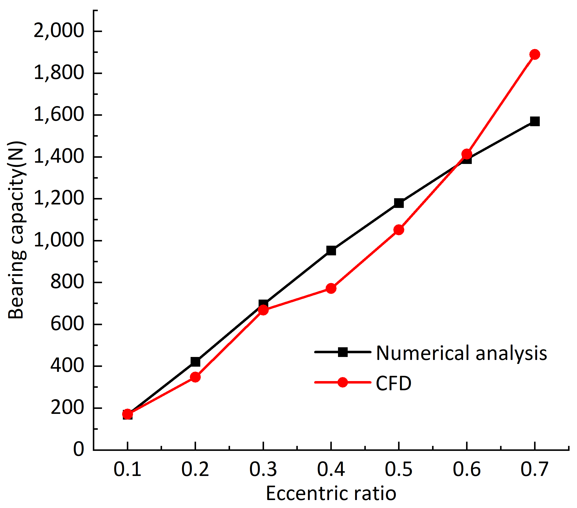
3.1. Correctness Verification of Calculation Method

Since the research content of this paper has not been verified by experiments, Ansys Fluent [29] software is used to compare with the calculation results. Figure 6 shows the influence curve of eccentricity on the bearing capacity of the aerostatic bearing under the two methods. It can be seen from Figure 6 that the bearing capacity calculated by the two methods increases with the increase in eccentricity, and the bearing capacity calculated by the two methods is almost the same when the eccentric ratio is 0.1, 0.2, 0.3 and 0.6. On the whole, with the increase in eccentricity, the bearing capacity obtained by the two calculation methods is slightly different, but the growth trend is approximately the same. The grid division and different parameter settings will make the calculation results slightly different. It can be considered that the method applied in this paper is in line with reality.

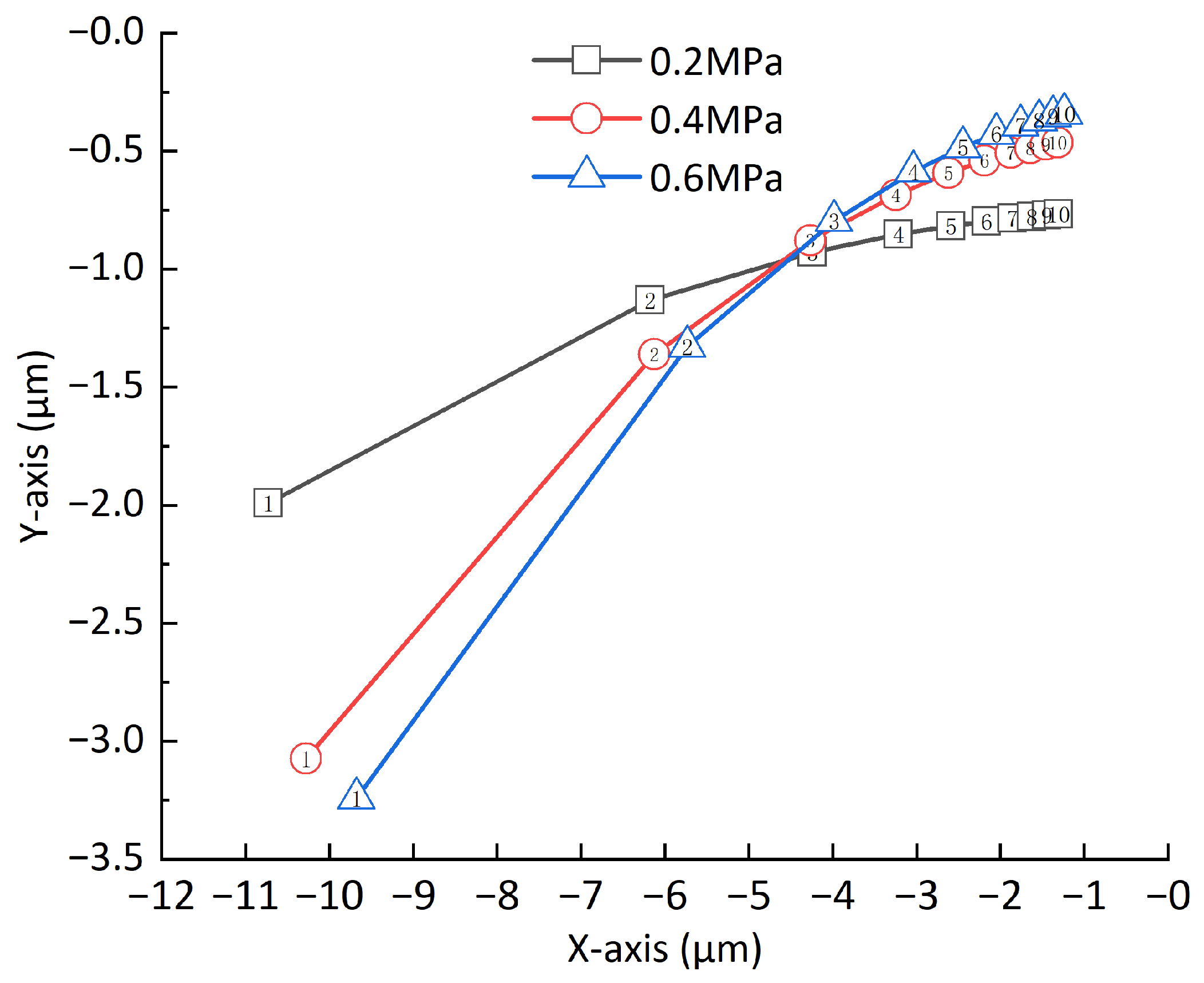
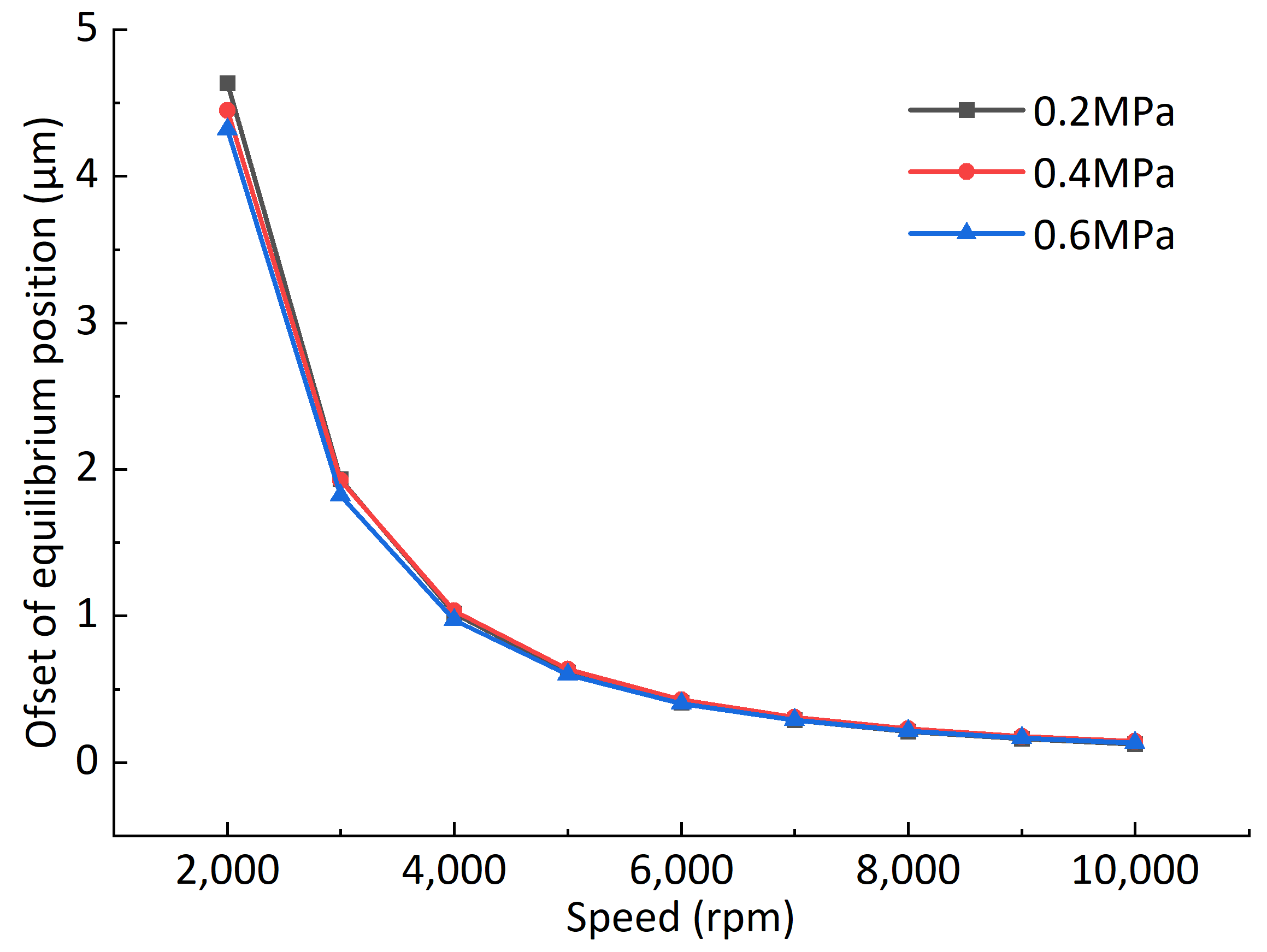
3.2. Effect of Rotational Speed and Gas Supply Pressure on Rotor Equilibrium Position

Under different rotational speeds, the changes in the rotor equilibrium position are as shown in Figure 7; the number in the symbol represents the rotational speed and the unit is 1000 rmp, and the center of the journal is the origin of the Cartesian coordinate system. The offset amplitude of the rotor equilibrium position to the journal center at different speeds and air supply pressures is shown in Figure 8. From Figure 7, it can be seen that the increase in rotational speed thus enhances the dynamic pressure effect, the rotor equilibrium position gradually moves to the journal center, and the movement amount gradually decreases with the increase in rotational speed. Under different air supply pressures, the equilibrium position of the rotor is also different. The higher the pressure, the closer the rotor center is to the journal center. Compared with the air supply pressure, the speed has a greater impact on the rotor equilibrium position. When the speed is greater than 4000 rpm, the change in the rotor equilibrium position slows down. From Figure 8, under different air supply pressures, the offset of the rotor equilibrium position caused by increasing the rotational speed is approximately the same. When the rotor speed increases from 1000 to 2000 rpm, the offset of the rotor equilibrium position is around 4.5 μ m. As the speed continues to increase, the offset decreases sharply, and when the speed increases from 9000 to 10,000 rpm, the offset of the rotor equilibrium position is around 0.15 μ m.

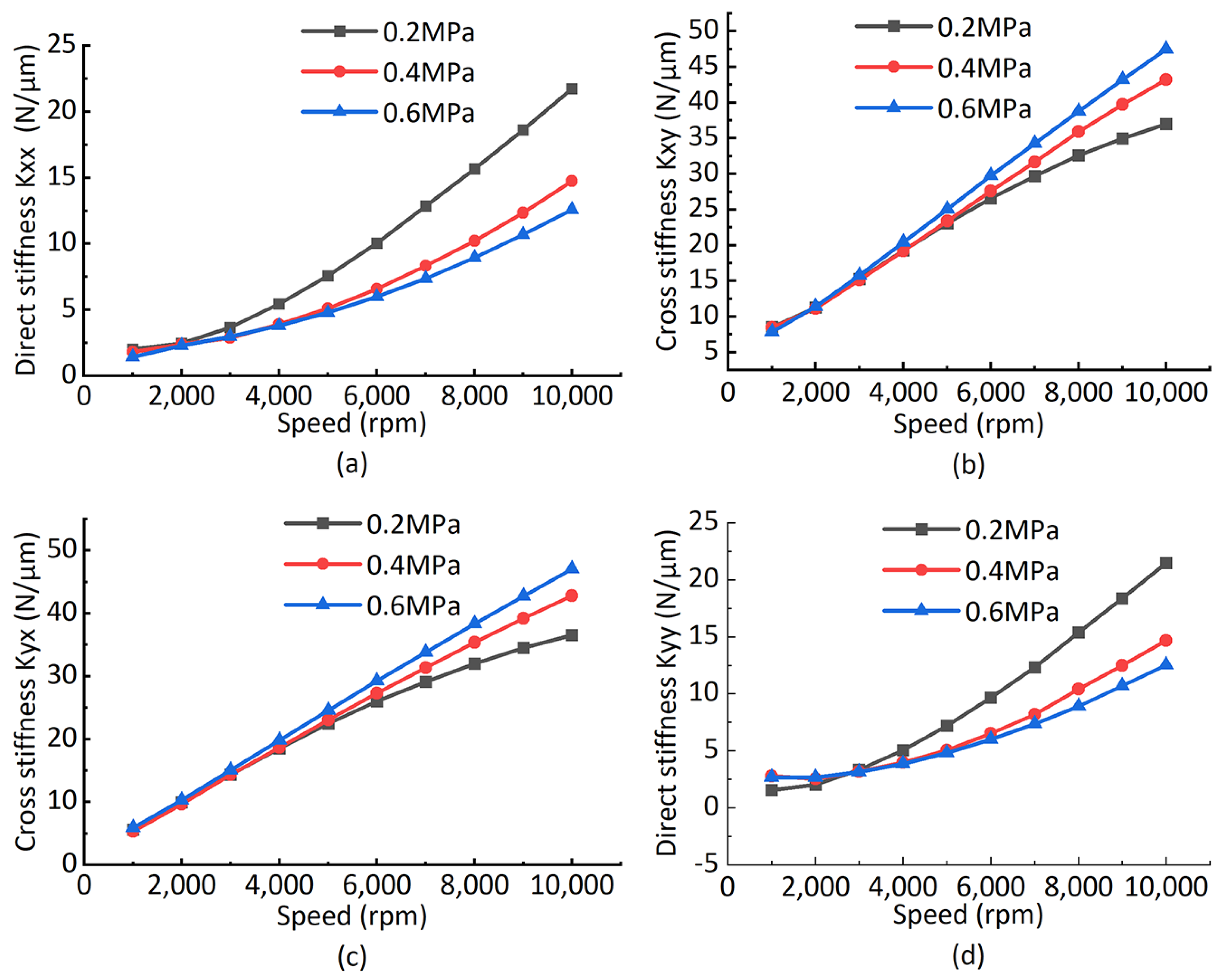
3.3. Effect of Equilibrium Position on Bearing Stiffness

Let the equilibrium position move at different rotational speeds by 0.1 μ m along the X and Y direction, respectively, to calculate the corresponding direct stiffness and cross stiffness, as is shown in Figure 9. It can be seen that with the increase in rotational speed, the direct stiffness and cross stiffness at the rotor equilibrium position increase at the same time, and the cross stiffness is greater than the direct stiffness. This is due to the existence of the deviation angle, and the maximum circumferential pressure of the rotor is near the minimum gas film gap. Different air supply pressures have different effects on the stiffness at the rotor equilibrium position. Increasing the air supply pressure will reduce the direct stiffness in the X and Y directions at the rotor equilibrium position, and the cross stiffness in the X and Y directions will increase with the increase in air supply pressure. The increase in rotational speed enhances the dynamic pressure effect and the bearing stiffness, which is consistent with the previous research results. The increase in bearing stiffness further leads to the increase in gas film force at the original equilibrium position. Thus, the resultant force is greater than zero. Under the action of gas film force, the minimum gas film gap of the rotor increases. The increase in the minimum gas film gap leads to a decrease in gas film force and an increase in the UMP, which finally reaches a new equilibrium position. It can explain the phenomenon that the equilibrium position gradually moves towards the center of the journal with the increase in rotational speed, described in Section 3.2.

3.4. Influence of the UMP on Rotor Equilibrium Position

The amplitude of the UMP corresponding to the equilibrium position of the rotor under different air supply pressures and different speeds is shown in Figure 10. The variations in the rotor equilibrium position caused by the UMP under different air supply pressures and different speeds are shown in Figure 11. From Figure 10, it can be seen that with the increase in rotational speed, the rotor equilibrium position moves to the journal center, and the amplitude of UMP will decrease sharply. When considering the UMP, the rotor will reach a new equilibrium position under the combined action of the UMP and the gas film force. From Figure 11, it can be seen that the UMP has a great impact on the equilibrium position at low speed. With the increase in speed, the rotor gradually moves to the journal center, and the impact of the UMP gradually weakens. Combined with Section 3.2 and Section 3.3, the reason for this phenomenon is that the bearing stiffness is small at low speed and the equilibrium position is far from the journal center, i.e., the rotor eccentricity is large, resulting in a large amplitude of the UMP, which will have a great impact on the equilibrium position of the rotor. As can be seen from Figure 11, the influence degree of the UMP is slightly different with different air supply pressure. With the increase in rotor speed, the influence degree of the UMP on equilibrium position offset gradually decreases. When the speed is greater than 4000 rpm, the offset of the equilibrium position caused by UMP is less than 0.004 μ m, and the influence of the UMP caused by static eccentricity on the equilibrium position becomes small or even negligible. Compared with increasing the air supply pressure, increasing the speed to reduce the UMP caused by the static eccentricity of the motor rotor is a more effective method.

4. Conclusions

Based on the finite difference method, this paper establishes a simulation program of the rotor under the combined action of gravity, the gas film force and the unbalanced magnetic pull (UMP); the influence of different rotational speeds and air supply pressures on the rotor equilibrium position is studied, and the influence of the unbalanced magnetic pull (UMP) caused by rotor eccentricity on the rotor equilibrium position is studied, and we draw the following conclusions:
  • Due to the dynamic pressure effect, the rotor equilibrium position will gradually move to the journal center with the increase in rotational speed, and the moving amplitude is approximately 0.15–4.5 μ m; the offset amplitude decreases gradually with the increase in rotating speed. Thus, when the rotor works continuously at different speeds, it is necessary to remeasure the rotor position to obtain higher positioning accuracy.
  • With the increase in rotational speed, the direct stiffness and cross stiffness at the rotor equilibrium position increase at the same time. The cross stiffness is greater than the direct stiffness. The higher the air supply pressure is, the greater the cross stiffness at the rotor equilibrium position is and the smaller the direct stiffness is. Therefore, the load direction during operation should avoid the X and Y directions to reduce the disturbance to the rotor, so as to obtain better stability.
  • The unbalanced magnetic pull (UMP) will affect the rotor equilibrium position, and the influence degree increases sharply with the increase in rotor eccentricity. The influence range of the unbalanced magnetic pull (UMP) caused by rotor eccentricity on the equilibrium position is approximately 0.001–0.02 μ m. The effect can be reduced by increasing the rotational speed.

Author Contributions

Conceptualization, W.W.; methodology, P.S.; software, H.Y.; validation, P.S. and H.Y.; formal analysis, P.S. and H.Y.; investigation, P.S. and H.Y.; data curation, W.W. and G.Z.; writing—original draft preparation, W.W.; writing—review and editing, W.W.; visualization, G.Z. and W.W.; funding acquisition, P.S. and H.Y. All authors have read and agreed to the published version of the manuscript.

Funding

This research was funded by the National Natural Science Foundation of China, grant number 51875586.

Institutional Review Board Statement

Not applicable.

Informed Consent Statement

Not applicable.

Data Availability Statement

The data presented in this study are available on reasonable request from the corresponding author.

Conflicts of Interest

The authors declare no conflict of interest.

References

  1. Gao, Q.; Chen, W.; Lu, L.; Huo, D.; Cheng, K. Aerostatic bearings design and analysis with the application to precision engineering: State-of-the-art and future perspectives. Tribol. Int. 2019, 135, 1–17. [Google Scholar] [CrossRef]
  2. Karpat, Y. Influence of diamond tool chamfer angle on surface integrity in ultra-precision turning of singe crystal silicon. Int. J. Adv. Manuf. Technol. 2019, 101, 1565–1572. [Google Scholar] [CrossRef]
  3. Nanotech 250UPL V2 Ultra Precision Lathe. Available online: https://nanotechsys.com/machines/nanotech-250uplv2-ultra-precision-lathe/ (accessed on 3 April 2022).
  4. Zhang, G.; Zheng, J.; Yu, H.; Zhao, R.; Shi, W.; Wang, J. Rotation Accuracy Analysis of Aerostatic Spindle Considering Shaft’s Roundness and Cylindricity. Appl. Sci. 2021, 11, 7912. [Google Scholar] [CrossRef]
  5. Kim, U.; Lieu, D.K. Magnetic field calculation in permanent magnet motors with rotor eccentricity: Without slotting effect. IEEE Trans. Magn. 1998, 34, 2243–2252. [Google Scholar] [CrossRef]
  6. Di, C.; Bao, X.; Wang, H.; Lv, Q.; He, Y. Modeling and analysis of unbalanced magnetic pull in cage induction motors with curved dynamic eccentricity. IEEE Trans. Magn. 2015, 51, 1–7. [Google Scholar]
  7. Li, J.; Liu, Z.; Nay, L. Effect of radial magnetic forces in permanent magnet motors with rotor eccentricity. IEEE Trans. Magn. 2007, 43, 2525–2527. [Google Scholar] [CrossRef]
  8. Dorrell, D.G.; Popescu, M.; Ionel, D.M. Unbalanced Magnetic Pull Due to Asymmetry and Low-Level Static Rotor Eccentricity in Fractional-Slot Brushless Permanent-Magnet Motors with Surface-Magnet and Consequent-Pole Rotors. IEEE Trans. Magn. 2010, 46, 2675–2685. [Google Scholar] [CrossRef]
  9. Xiang, C.; Liu, F.; Liu, H.; Han, L.; Zhang, X. Nonlinear dynamic behaviors of permanent magnet synchronous motors in electric vehicles caused by unbalanced magnetic pull. J. Sound Vib. 2016, 371, 277–294. [Google Scholar] [CrossRef]
  10. Kim, U.; Lieu, D.K. Effects of magnetically induced vibration force in brushless permanent-magnet motors. IEEE Trans. Magn. 2005, 41, 2164–2172. [Google Scholar] [CrossRef]
  11. Kim, D.; Noh, M.D.; Park, Y.w. Unbalanced magnetic forces due to rotor eccentricity in a toroidally wound BLDC motor. IEEE Trans. Magn. 2016, 52, 1–4. [Google Scholar] [CrossRef]
  12. Zhang, Y.; Geng, H.; Zhou, J.; YU, L. Analytical calculation for magnetic field of permanent magnet synchronous motors with rotor eccentricity. J. Xi’an Jiaotong Univ. 2019, 53, 96–103. [Google Scholar]
  13. Han, X.; Palazzolo, A. Unstable force analysis for induction motor eccentricity. J. Sound Vib. 2016, 370, 230–258. [Google Scholar] [CrossRef]
  14. Kim, H.; Nerg, J.; Choudhury, T.; Sopanen, J.T. Rotordynamic simulation method of induction motors including the effects of unbalanced magnetic pull. IEEE Access 2020, 8, 21631–21643. [Google Scholar] [CrossRef]
  15. Guo, D.; Chu, F.; Chen, D. The unbalanced magnetic pull and its effects on vibration in a three-phase generator with eccentric rotor. J. Sound Vib. 2002, 254, 297–312. [Google Scholar] [CrossRef]
  16. Liu, H.; Wu, Y.; Wang, X.; Yan, P.; Zhang, X. Nonlinear normal modes and primary resonance for permanent magnet synchronous motors with a nonlinear restoring force and an unbalanced magnetic pull. Nonlinear Dyn. 2019, 97, 1197–1213. [Google Scholar] [CrossRef]
  17. Gustavsson, R.K.; Aidanpää, J.O. The influence of nonlinear magnetic pull on hydropower generator rotors. J. Sound Vib. 2006, 297, 551–562. [Google Scholar] [CrossRef]
  18. Zhao, D.; Dang, W.; Sun, W.; Guo, P. Influence of unbalanced magnetic pull on rub-impact rotor-bearing system. J. Huazhong Univ. Sci. Technol. 2019, 47, 34–39. [Google Scholar]
  19. Zhang, S.; Li, Z.; Xiong, Z. A theoretical and experimental study of forced spindle vibration under unbalanced magnetic forces in ultra-precision machining. Int. J. Adv. Manuf. Technol. 2019, 103, 4689–4694. [Google Scholar] [CrossRef]
  20. Gao, S.; Cheng, K.; Ding, H.; Fu, H. Multiphysics-based design and analysis of the high-speed aerostatic spindle with application to micro-milling. Proc. Inst. Mech. Eng. Part J J. Eng. Tribol. 2016, 230, 852–871. [Google Scholar] [CrossRef]
  21. Belforte, G.; Raparelli, T.; Viktorov, V.; Trivella, A.; Colombo, F. An experimental study of high-speed rotor supported by air bearings: Test RIG and first experimental results. Tribol. Int. 2006, 39, 839–845. [Google Scholar] [CrossRef]
  22. Zhang, S.; To, S.; Zhang, G.; Zhu, Z. A review of machine-tool vibration and its influence upon surface generation in ultra-precision machining. Int. J. Mach. Tools Manuf. 2015, 91, 34–42. [Google Scholar] [CrossRef]
  23. Chen, X.; Xu, J.; Fang, H.; Tian, R. Influence of cutting parameters on the ductile-brittle transition of single-crystal calcium fluoride during ultra-precision cutting. Int. J. Adv. Manuf. Technol. 2017, 89, 219–225. [Google Scholar] [CrossRef]
  24. Sun, Y.; Chen, W.; Liang, Y.; An, C.; Chen, G.; Su, H. Dynamic error budget analysis of an ultraprecision flycutting machine tool. Int. J. Adv. Manuf. Technol. 2015, 76, 1215–1224. [Google Scholar] [CrossRef]
  25. Cheung, C.F.; To, S.; Lee, W.B. Anisotropy of surface roughness in diamond turning of brittle single crystals. Mater. Manuf. Process. 2002, 17, 251–267. [Google Scholar] [CrossRef]
  26. To, S.; Cheung, C.F.; Lee, W.B. Influence of material swelling on surface roughness in diamond turning of single crystals. Mater. Sci. Technol. 2001, 17, 102–108. [Google Scholar] [CrossRef]
  27. Zhang, S.; To, S.; Cheung, C.F.; Wang, H. Dynamic characteristics of an aerostatic bearing spindle and its influence on surface topography in ultra-precision diamond turning. Int. J. Mach. Tools Manuf. 2012, 62, 1–12. [Google Scholar] [CrossRef]
  28. Jiangming, N. Dynamic stability and debugging of aerostatic-pressurized bearings in magnetic disk comprehensive instrumentation. J. Huazhong Univ. Sci. Technol. 1985, 13, 69–74. [Google Scholar]
  29. Ansys Fluent. Available online: https://www.ansys.com/zh-cn/products/fluids/ansys-fluent (accessed on 3 April 2022).
Figure 1. Aerostatic motorized spindle.
Electronics 11 01434 g001
Figure 2. Force model.
Electronics 11 01434 g002
Figure 3. Aerostatic motorized spindle.
Electronics 11 01434 g003
Figure 4. The five-point difference method.
Electronics 11 01434 g004
Figure 5. Calculation flowchart considering UMP.
Electronics 11 01434 g005
Figure 6. Influence curve of eccentricity on bearing capacity under two methods.
Electronics 11 01434 g006
Figure 7. Rotor equilibrium position under different pressures and speeds.
Electronics 11 01434 g007
Figure 8. Offset of rotor equilibrium position under different pressures and speeds.
Electronics 11 01434 g008
Figure 9. Bearing stiffness curve at different rotor equilibrium positions: (a) direct stiffness in X direction; (b) cross stiffness in X direction; (c) cross stiffness in Y direction; (d) direct stiffness in X direction.
Electronics 11 01434 g009
Figure 10. Amplitude of the UMP.
Electronics 11 01434 g010
Figure 11. Offset of rotor equilibrium position caused by the UMP.
Electronics 11 01434 g011
Table 1. Structural parameters of motorized spindle.
ParameterValue
Journal radius R 1 (mm)25
Motor stator radius R 2 (mm)21.89
Journal length L 1 (mm)160
Motor length L 2 (mm)62.5
Throttle slit width H ( μ m)80
Slit depth Y (mm)20
Mean gas film gap ( C 1 ) ( μ m)20
Mean magnetic gap ( C 2 ) (mm)0.58
Environment pressure ( P a ) (mm) (MPa)0.1
Number of slits5
Circumferential slit angle4 π /15
Publisher’s Note: MDPI stays neutral with regard to jurisdictional claims in published maps and institutional affiliations.

