
Detection and Diagnosis of Stator and Rotor Electrical Faults for Three-Phase Induction Motor via Wavelet Energy Approach


 , ,
, ,  ,
,  and
and 
Abstract
:1. Introduction
Literature Review and Motivation
- Development of a real-time fault detection algorithm for induction motors using wavelet packet transform;
- Use of Entropy Power Energy (EE) of high frequency subbands of the current signal to determine the condition of the induction motor and, moreover, to classify the type of the fault;
- Calculation of threshold values to differentiate different faults from EE energy signal;
- The real-time implementation and test of the algorithm on real equipment;
- Generalizing the algorithm by testing the algorithm on several induction motors of the same power rating with different parameters.
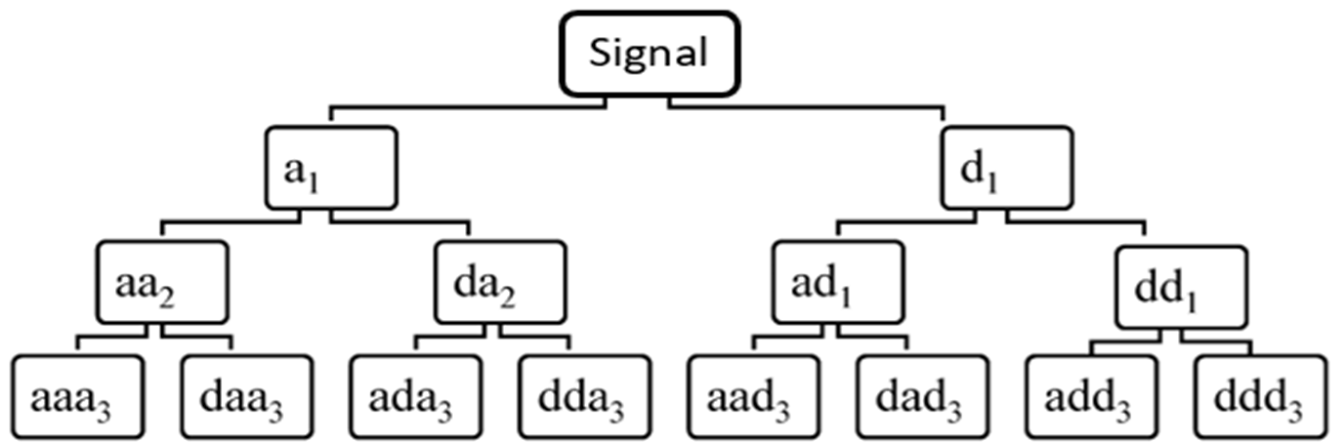
2. Wavelet Packet Transform and Wavelet Energy
3. Modeling of a 3-Phase Induction Motor with Electrical Faults
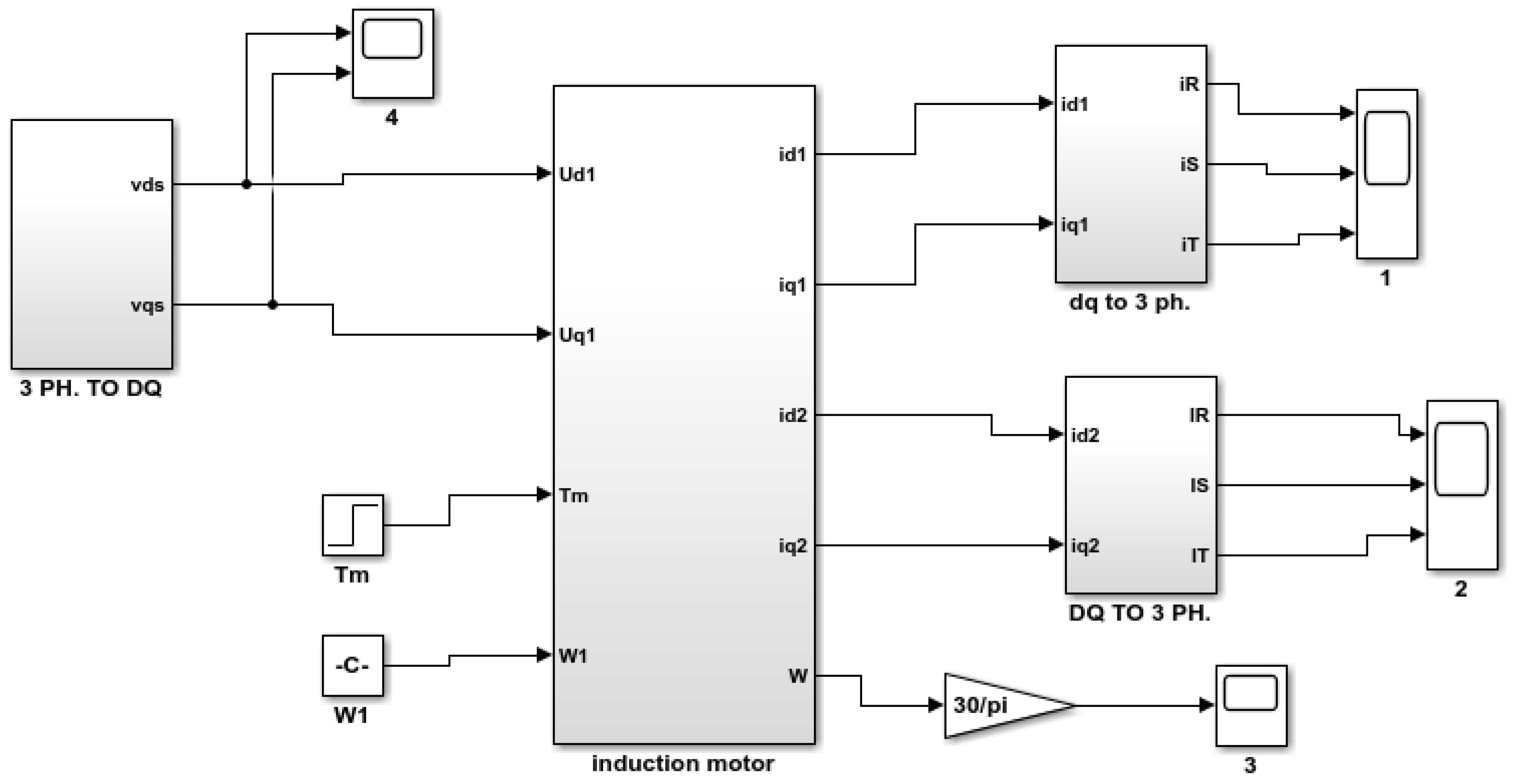
3.1. Modelling the Healthy Condition
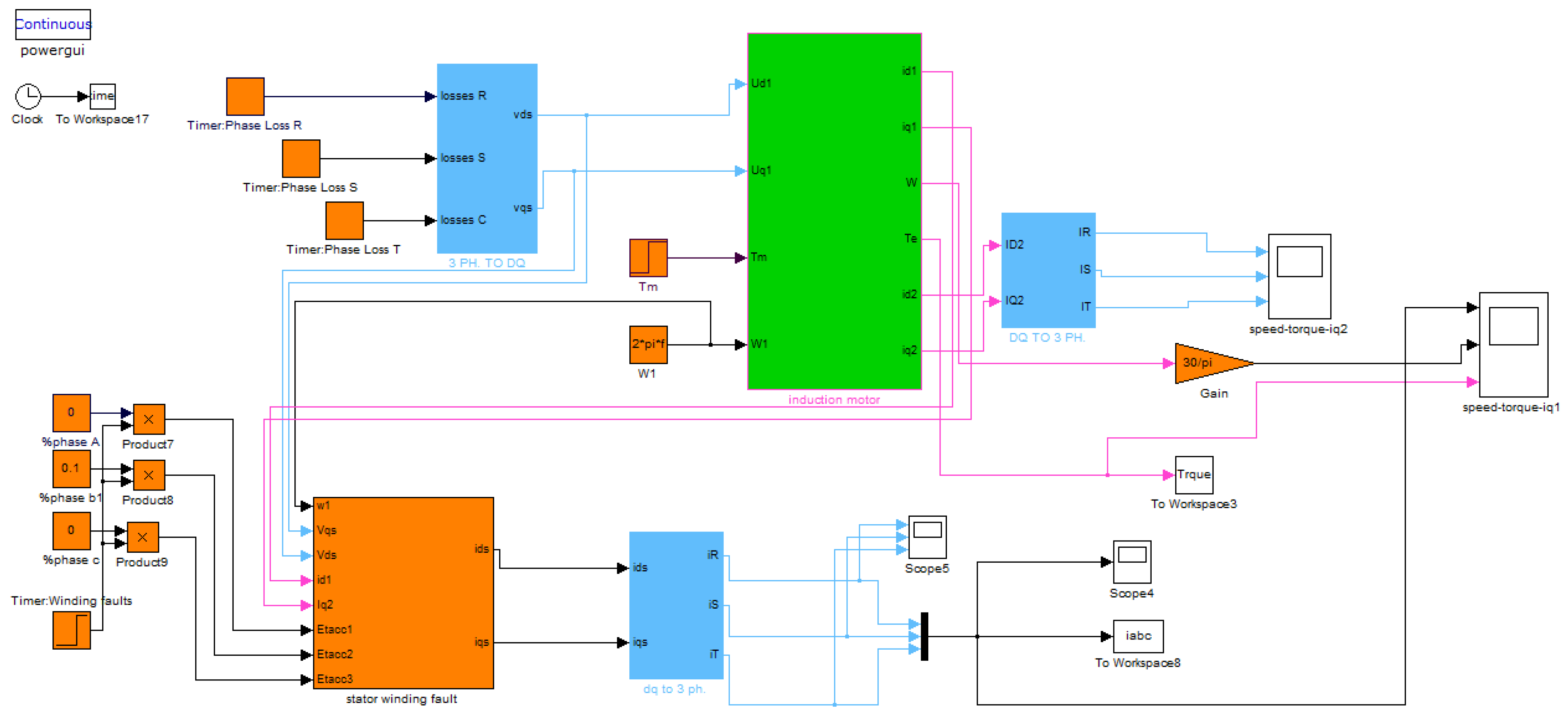
3.2. Modeling the Faulty Condition
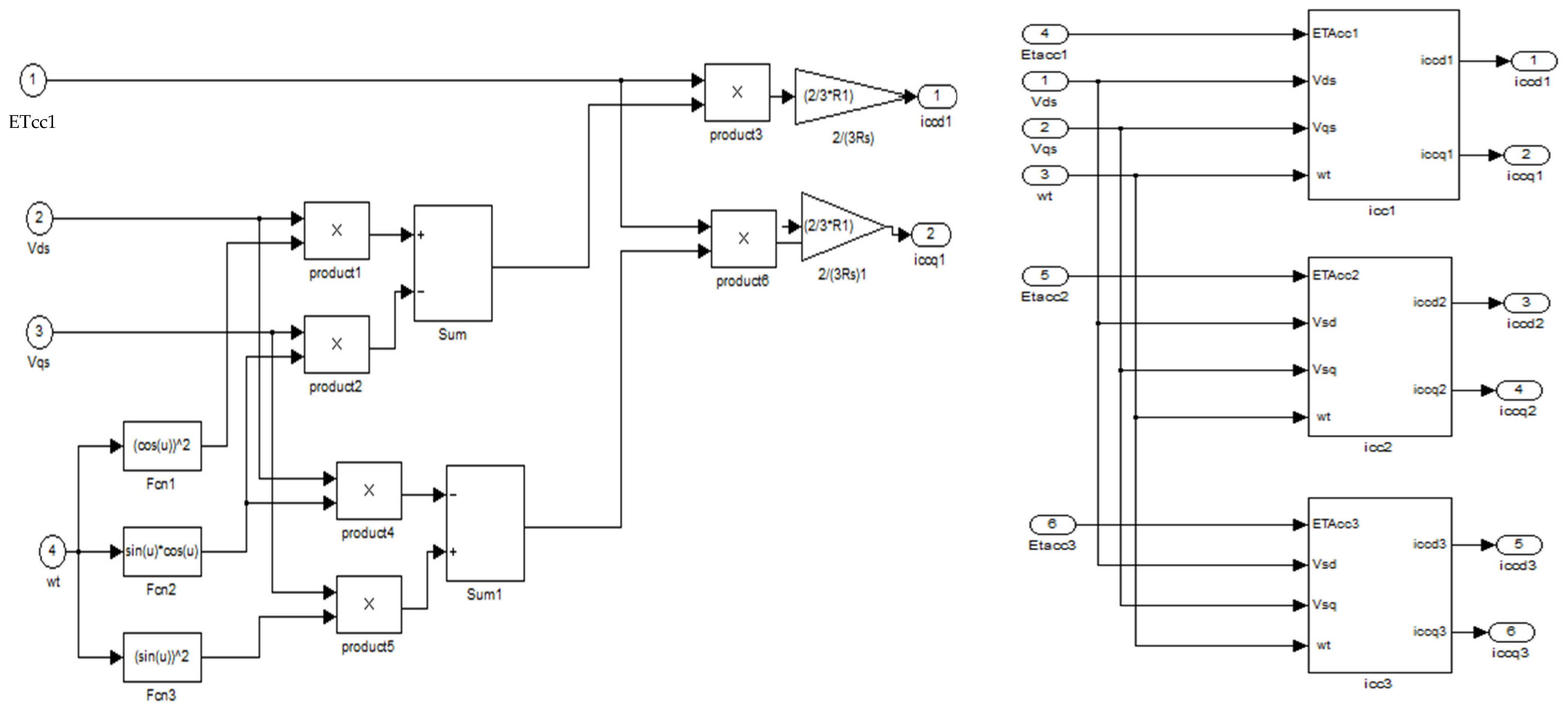
3.2.1. Fault in the Stator of the Motor
- The localization parameter (): This represents the angle between the new winding, which is generated by the fault, and the first phase winding (a). The value of this angle can be 0°, 120°, or 240° according to the three phases, called a, b, and c.
- The detection parameter () represents the percentage of inter-turn short circuit winding, where this ratio is obtained by dividing the number of inter-turn short circuit winding by the total number of the stator winding in one phase. The short circuit current under d-q axis frame can be represented as shown in the following equations [31]:
3.2.2. Fault in Rotor Part
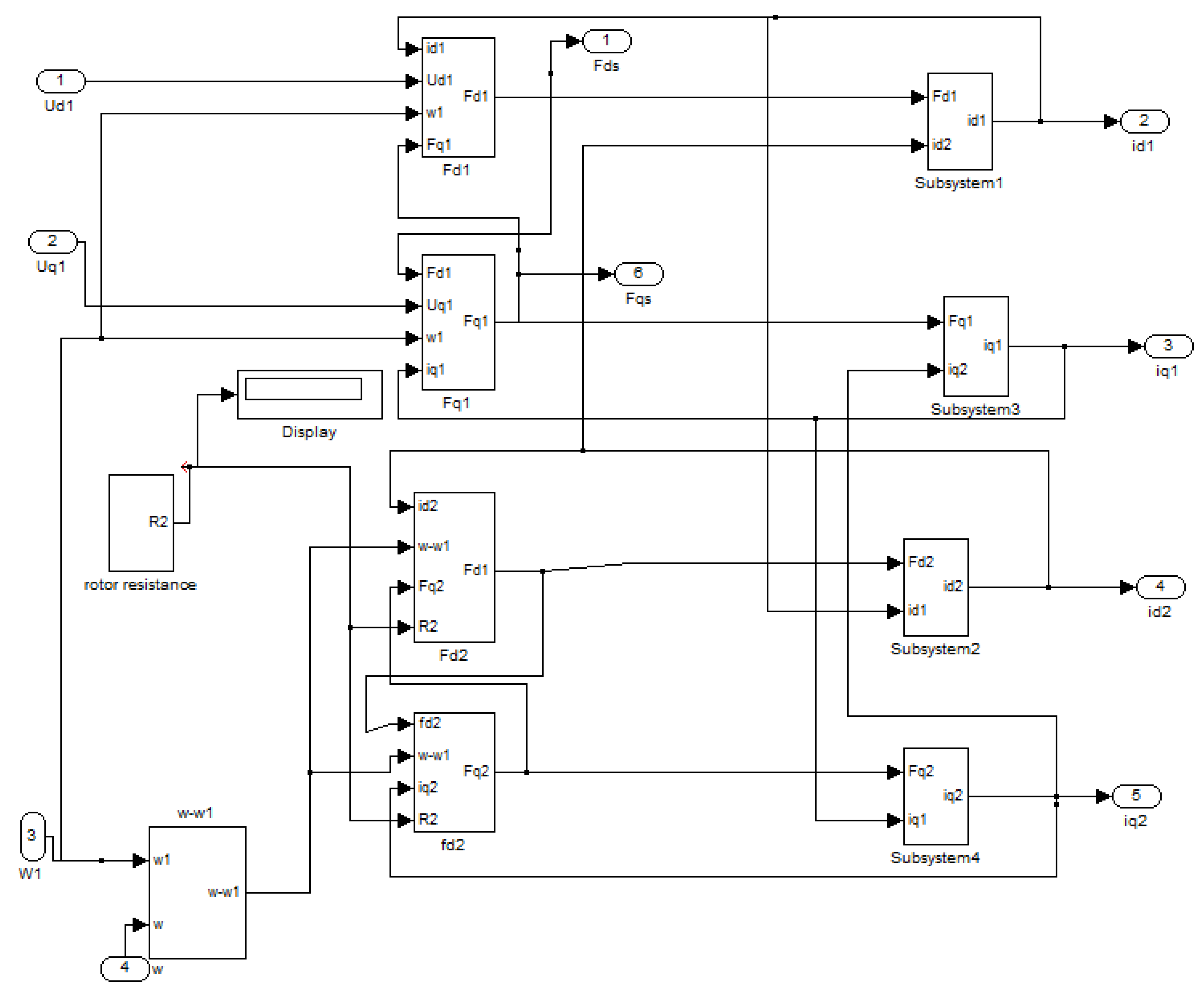
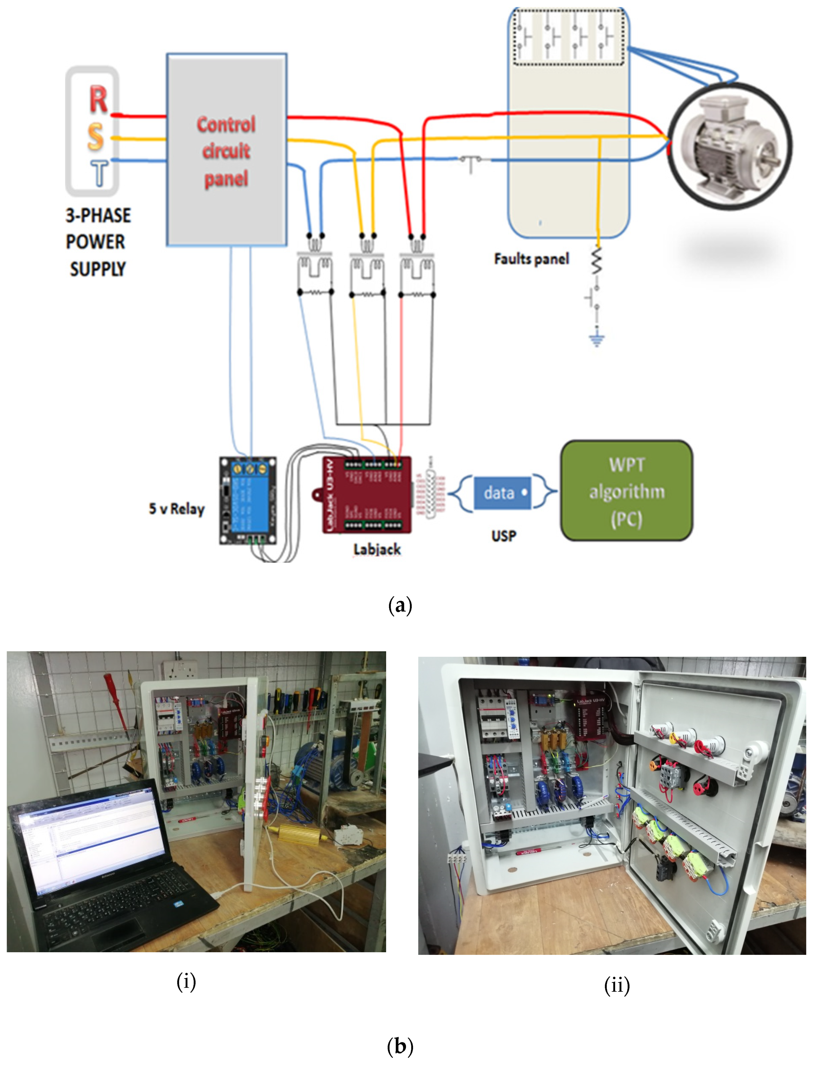
4. Simulink Model of the Proposed Technique and Real Time Data Collection
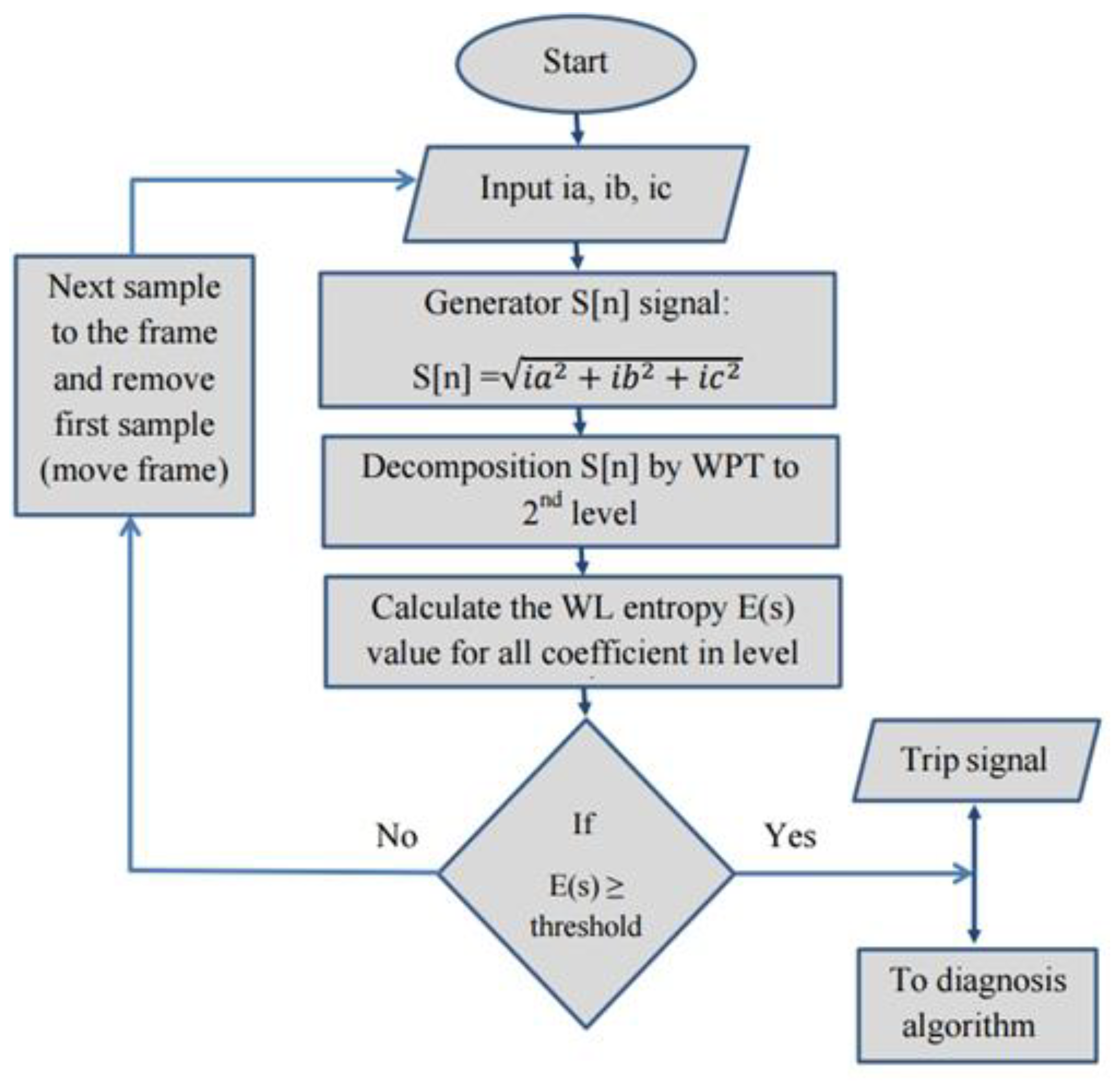
5. Proposed Fault Detection and Diagnosis Algorithm
Proposed Fault Detection Threshold
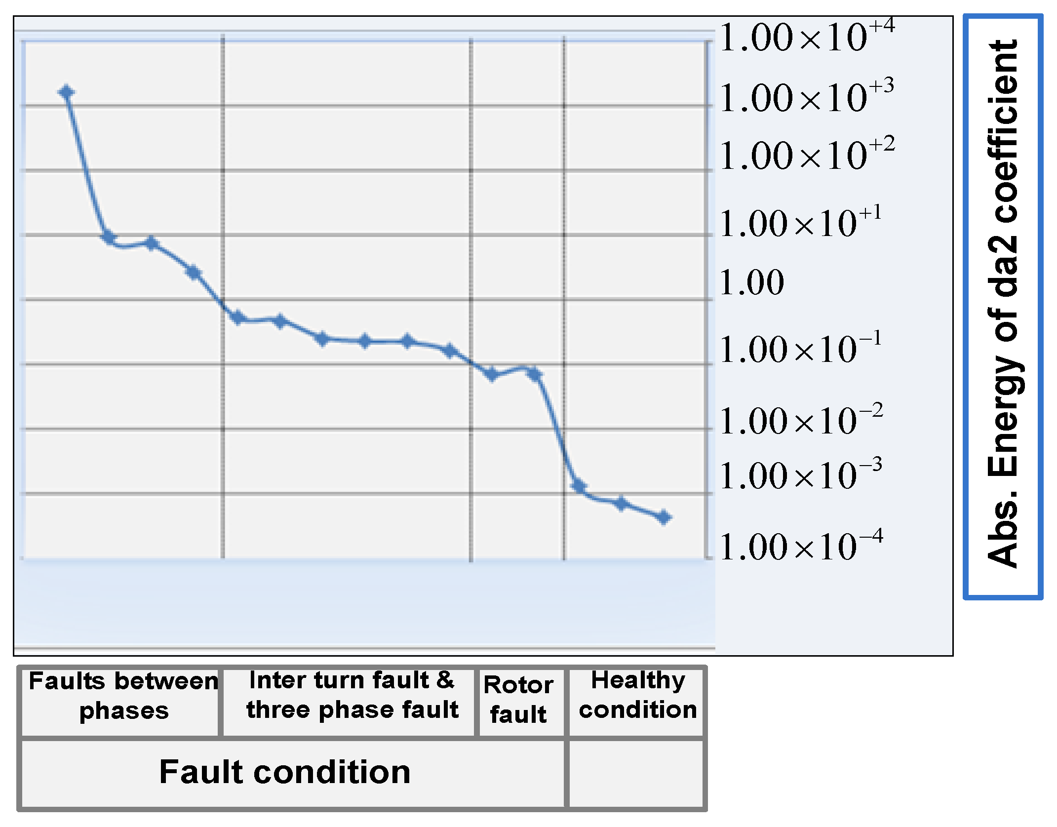
6. Proposed Fault Diagnosis Method—Threshold Values
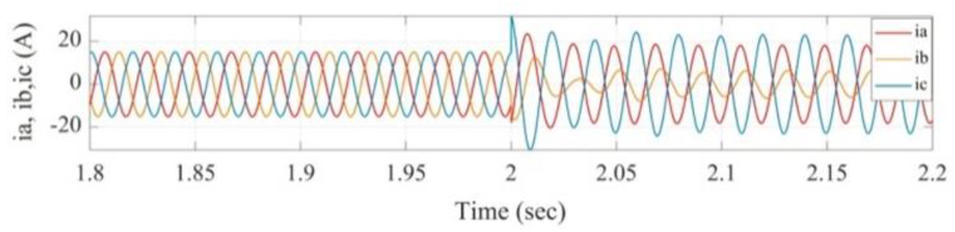
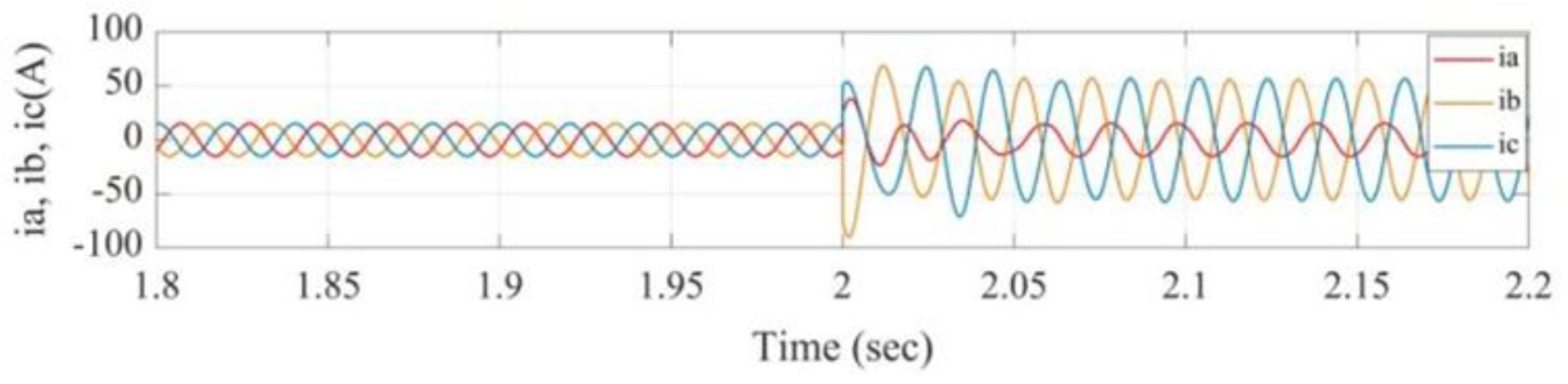
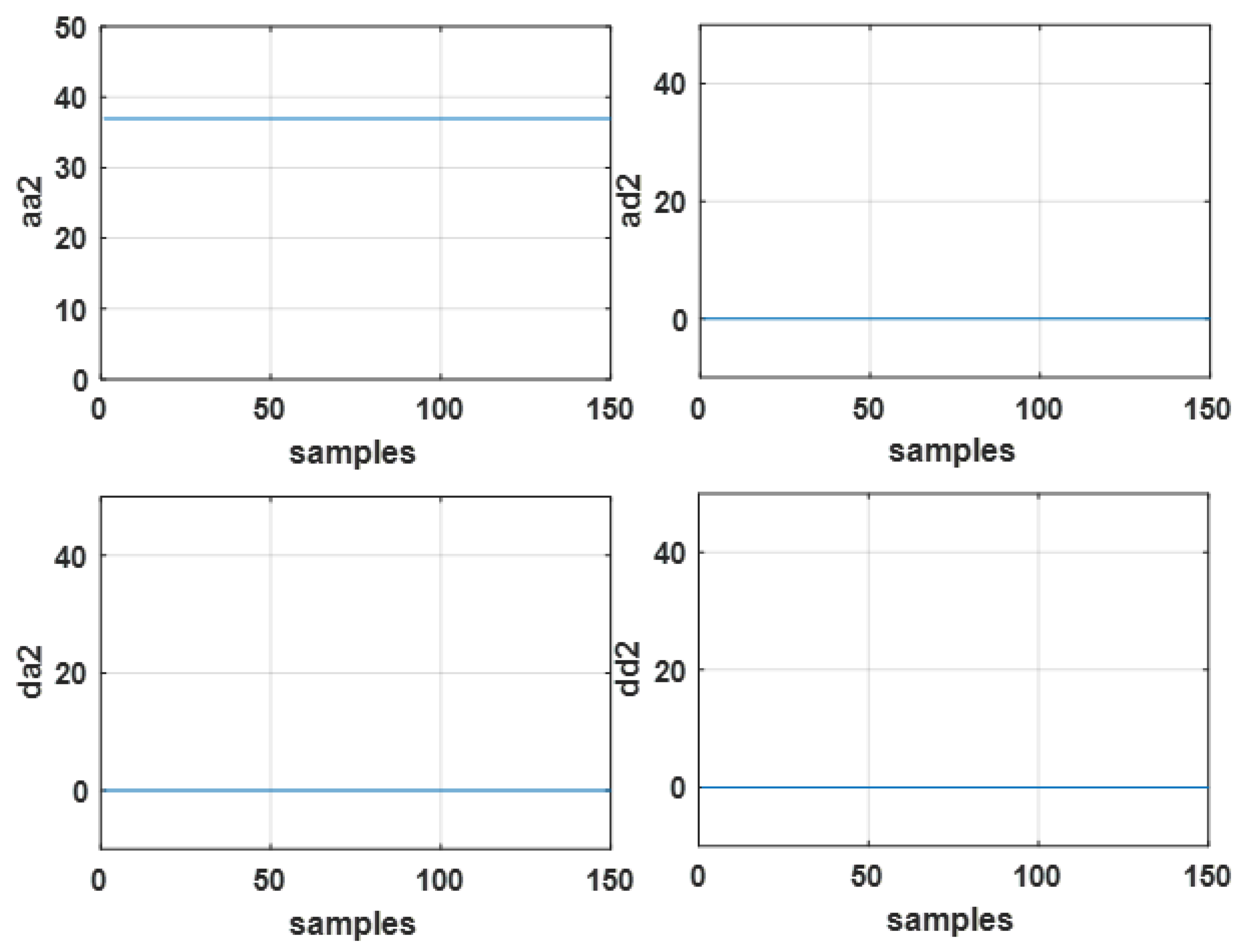
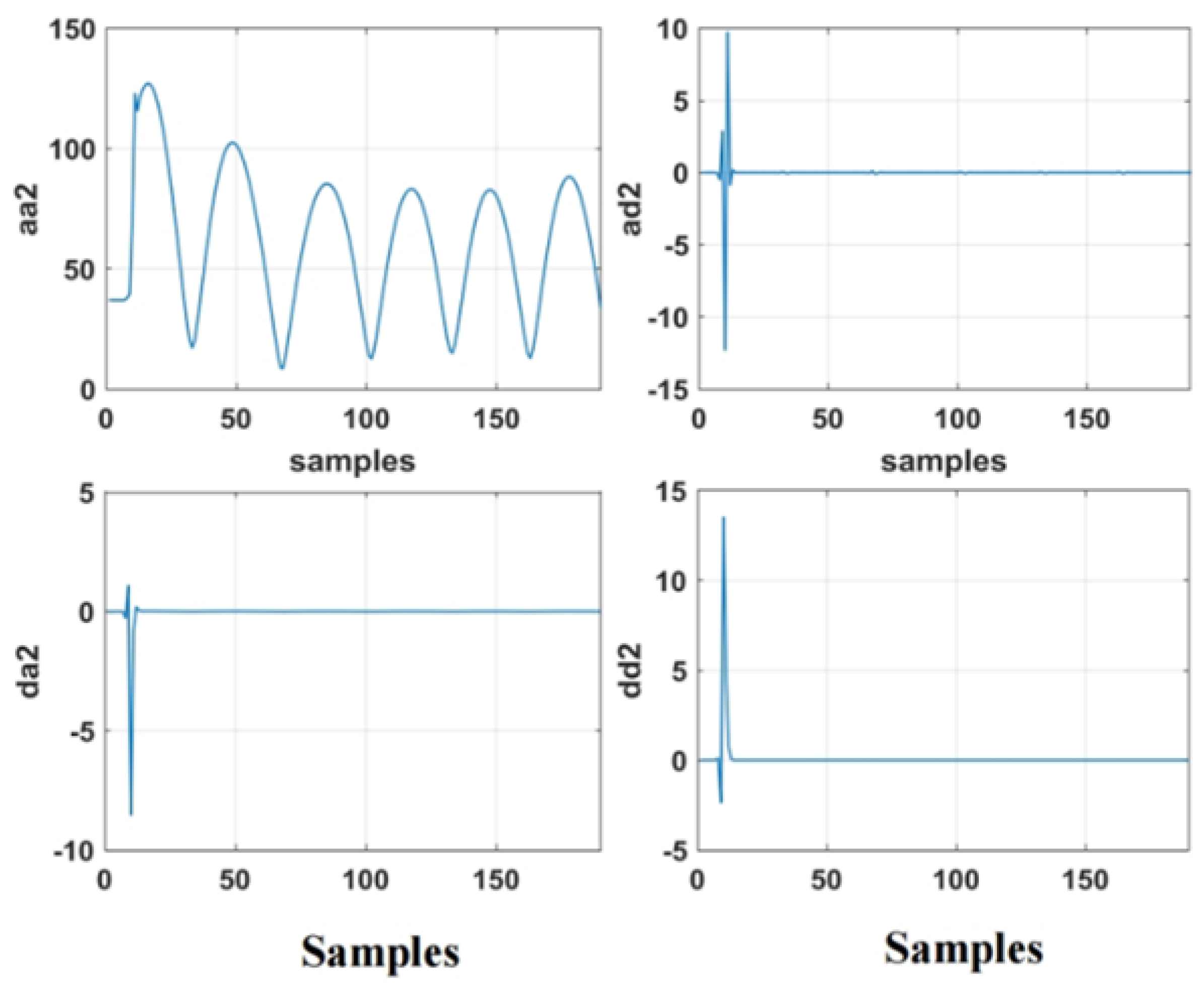
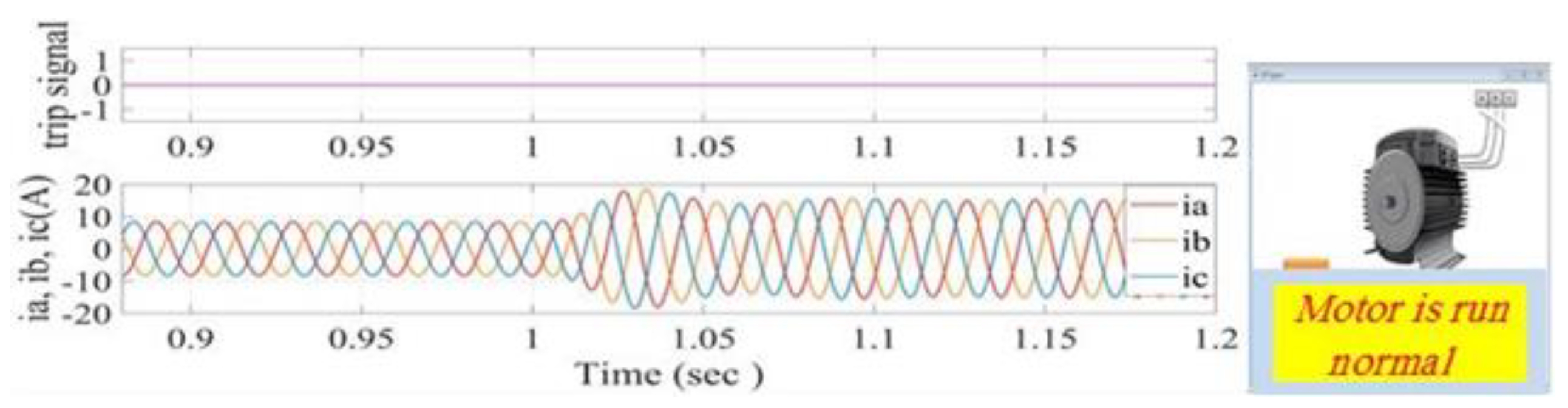
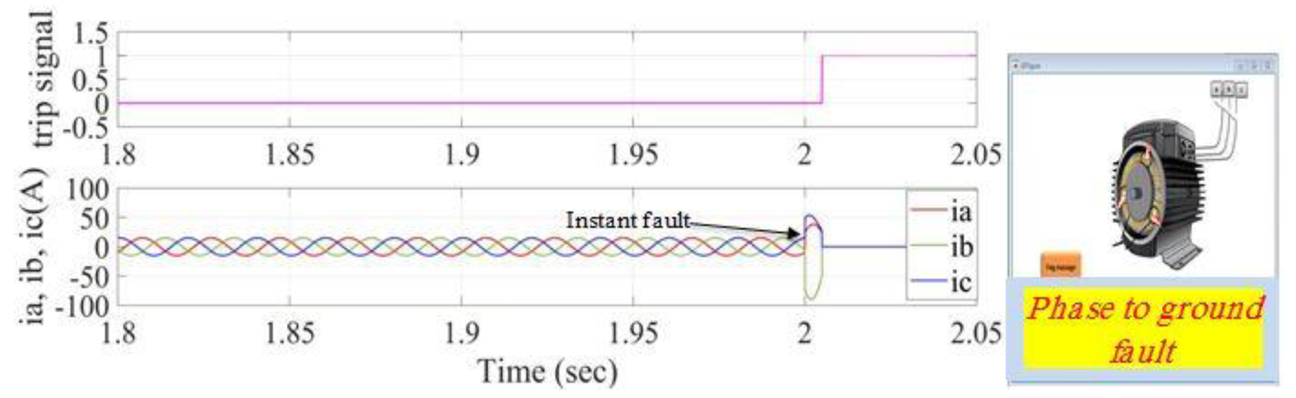
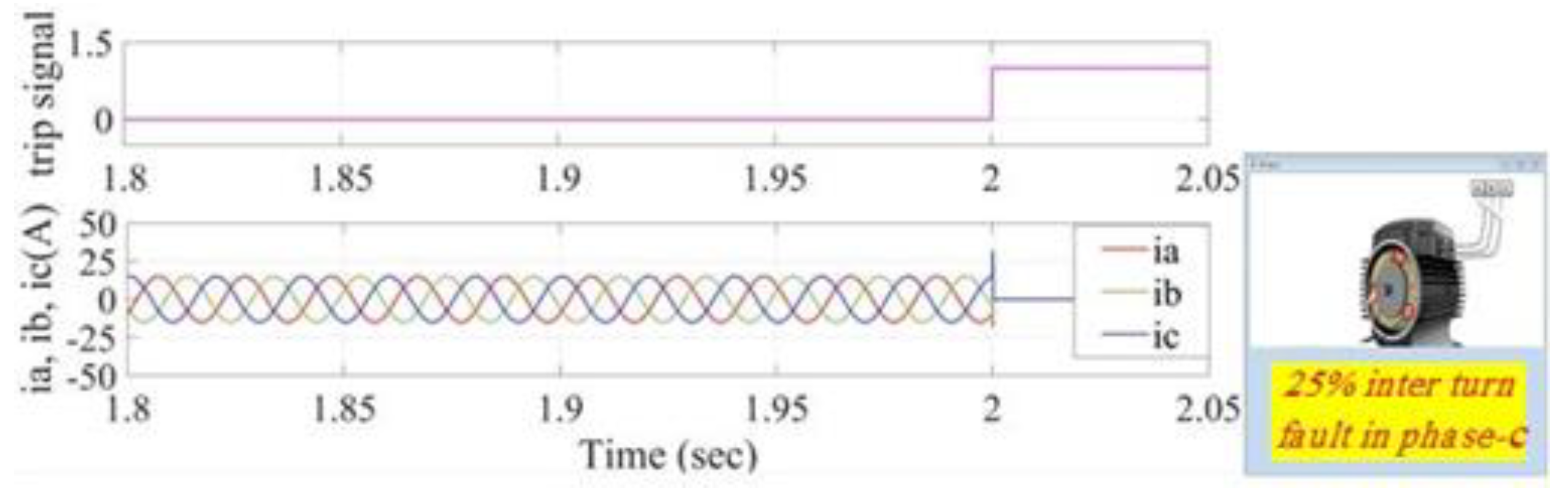
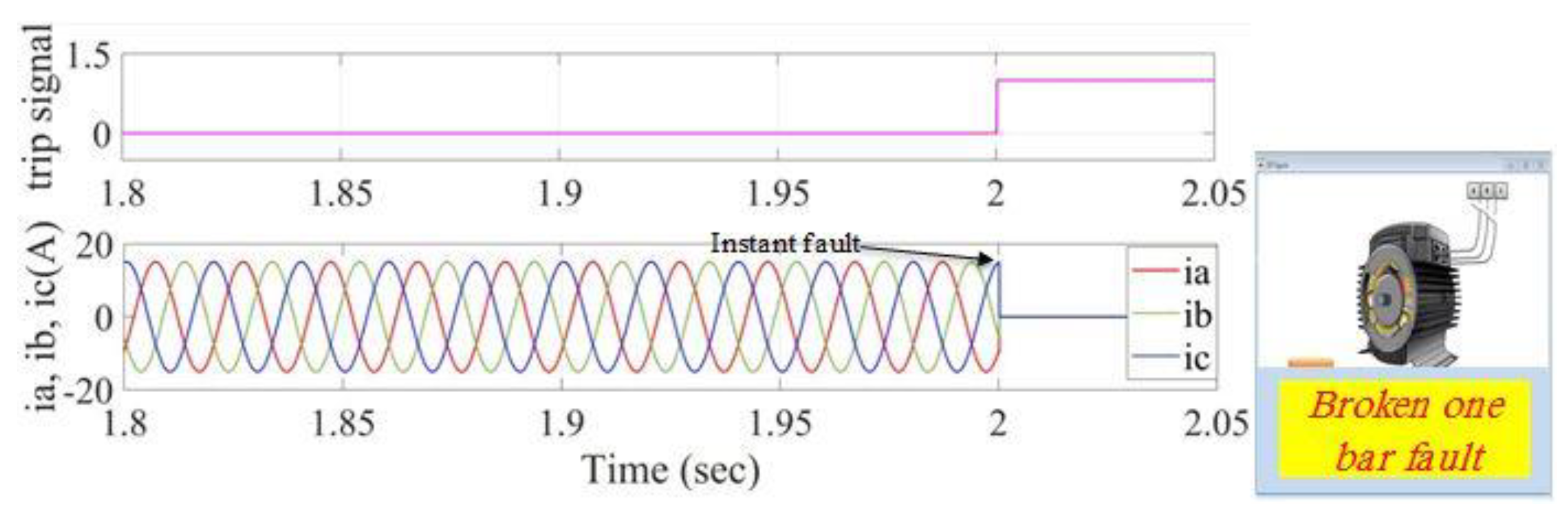
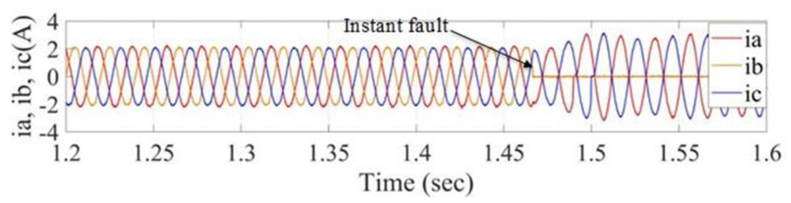
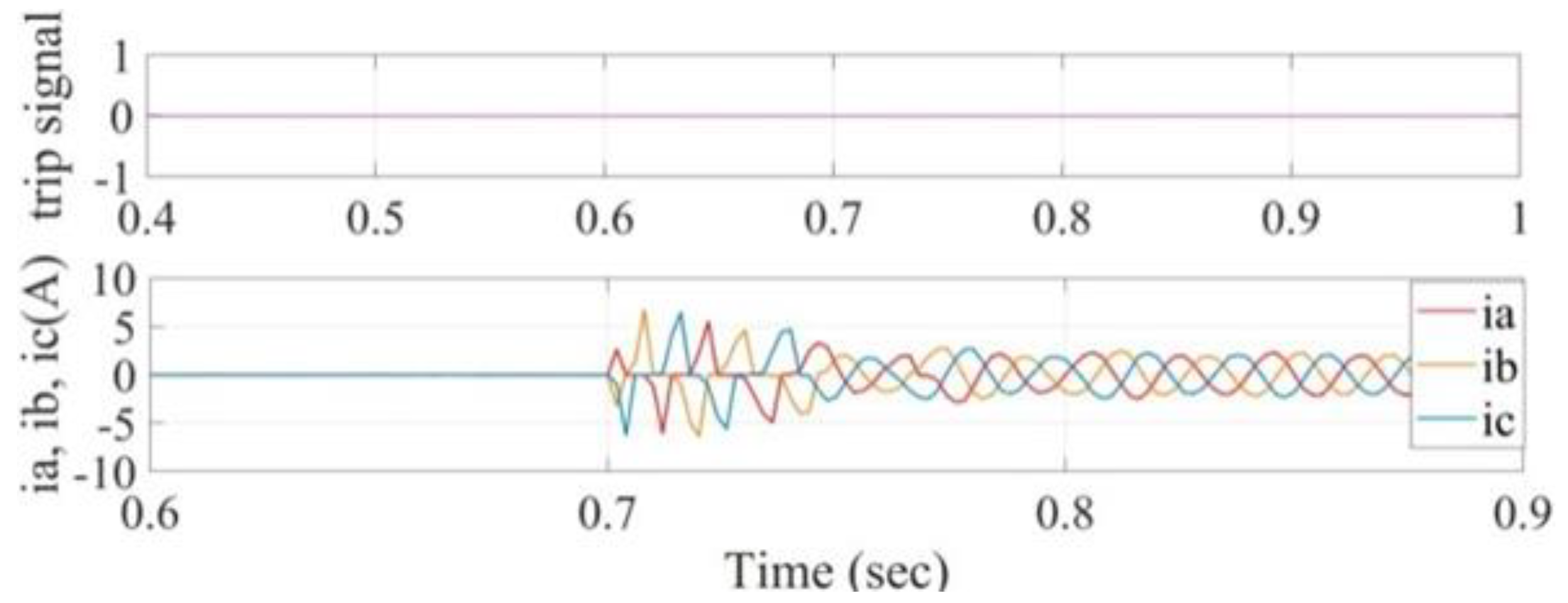
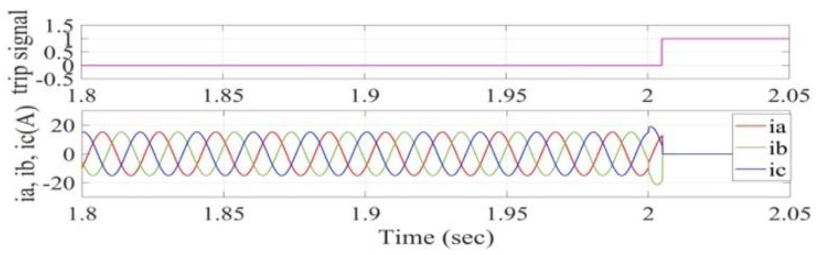
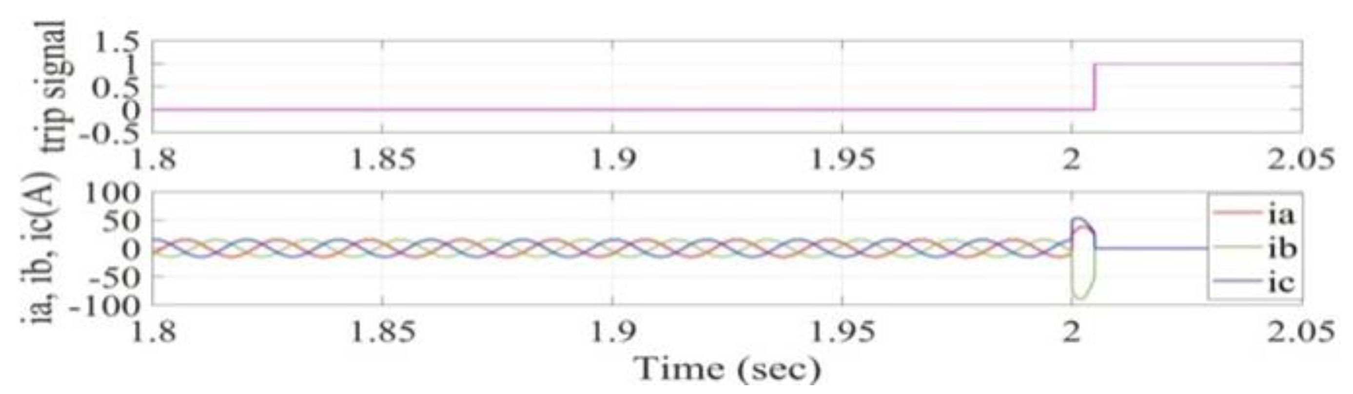
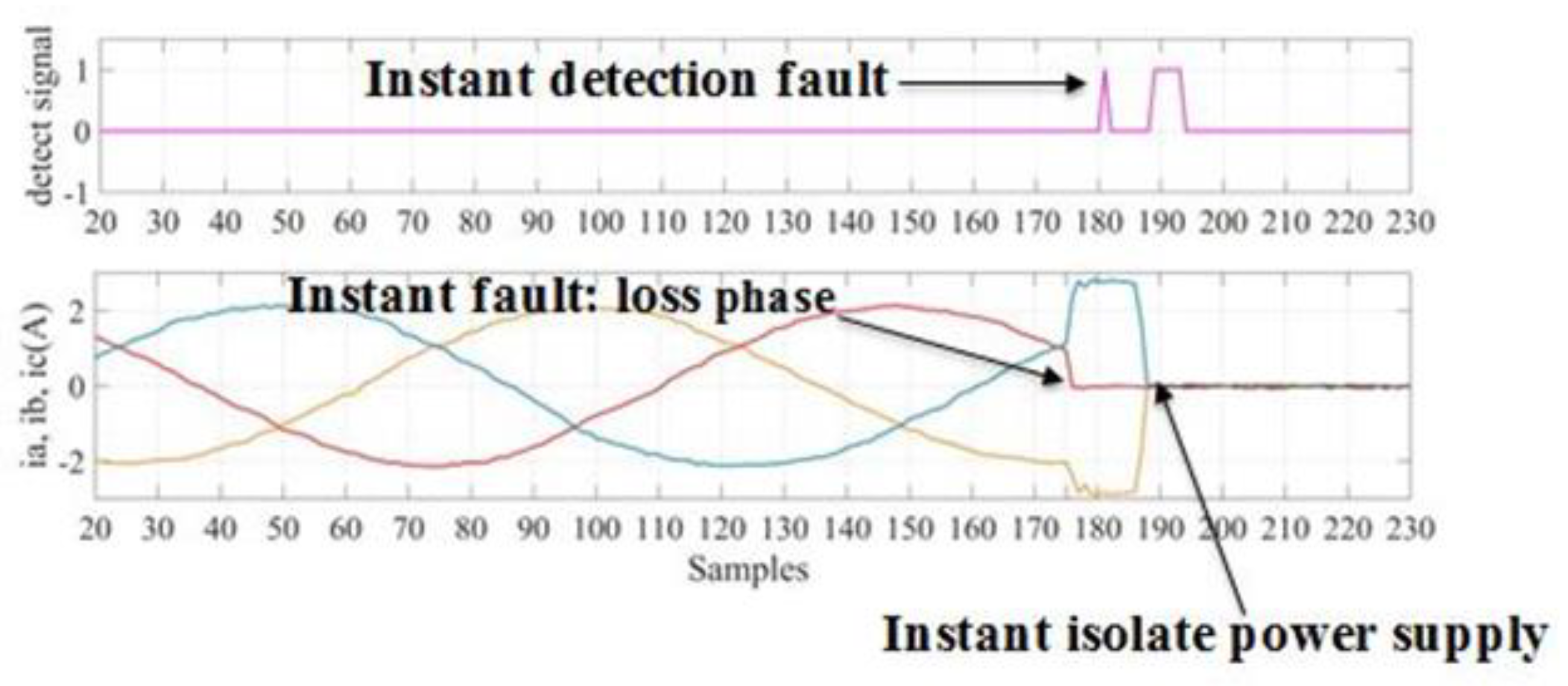
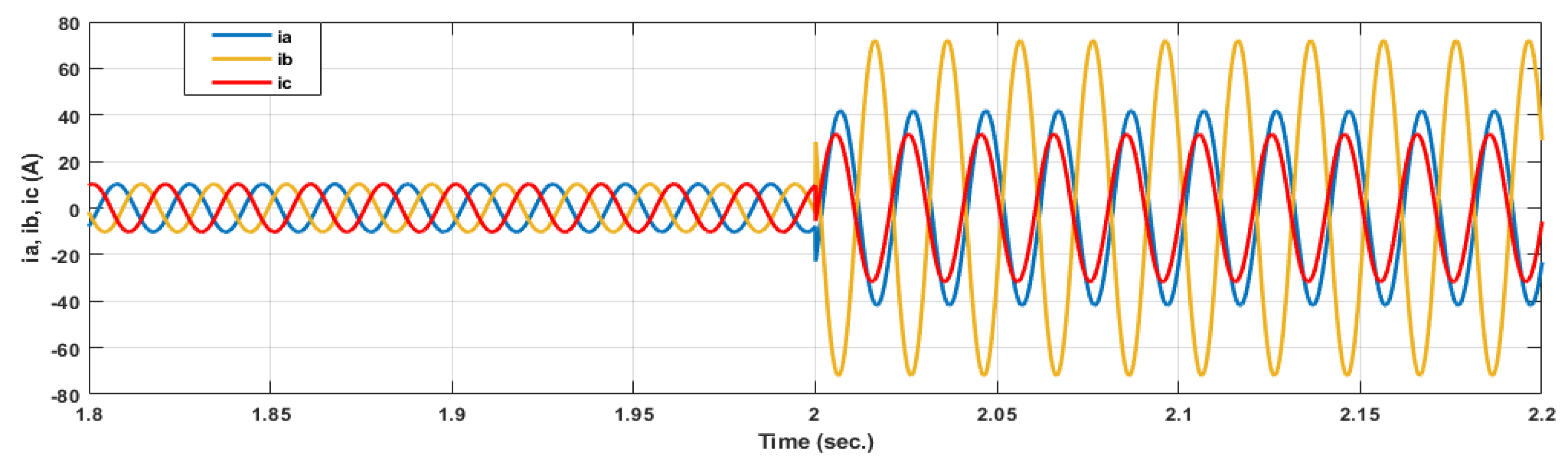
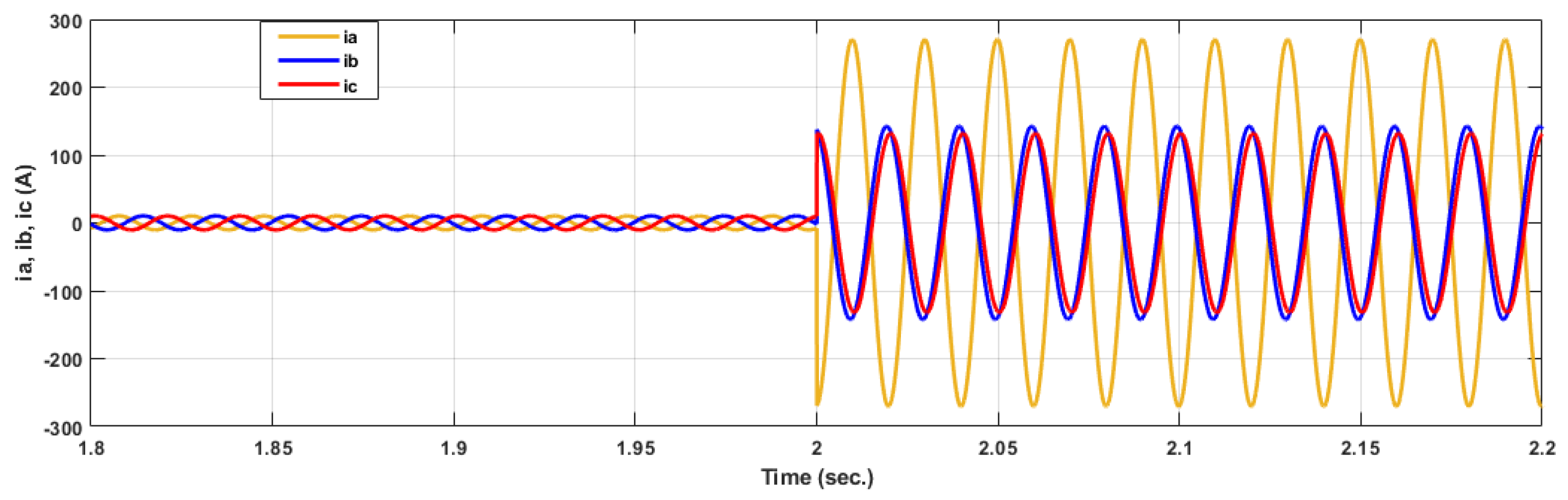
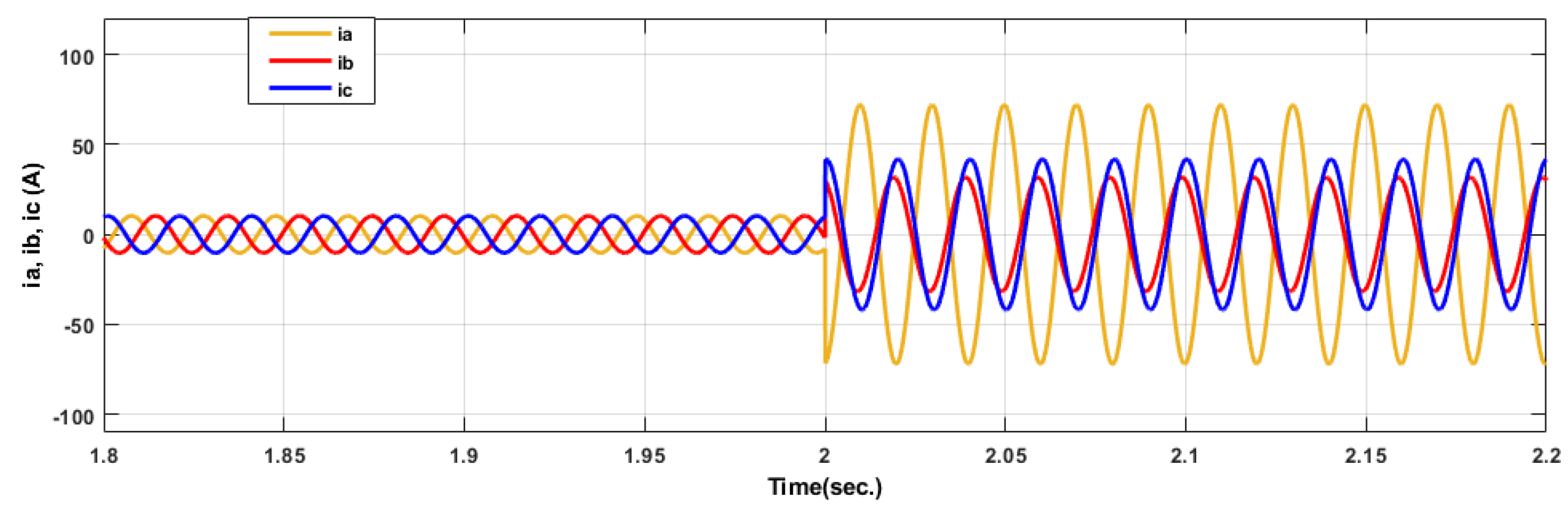
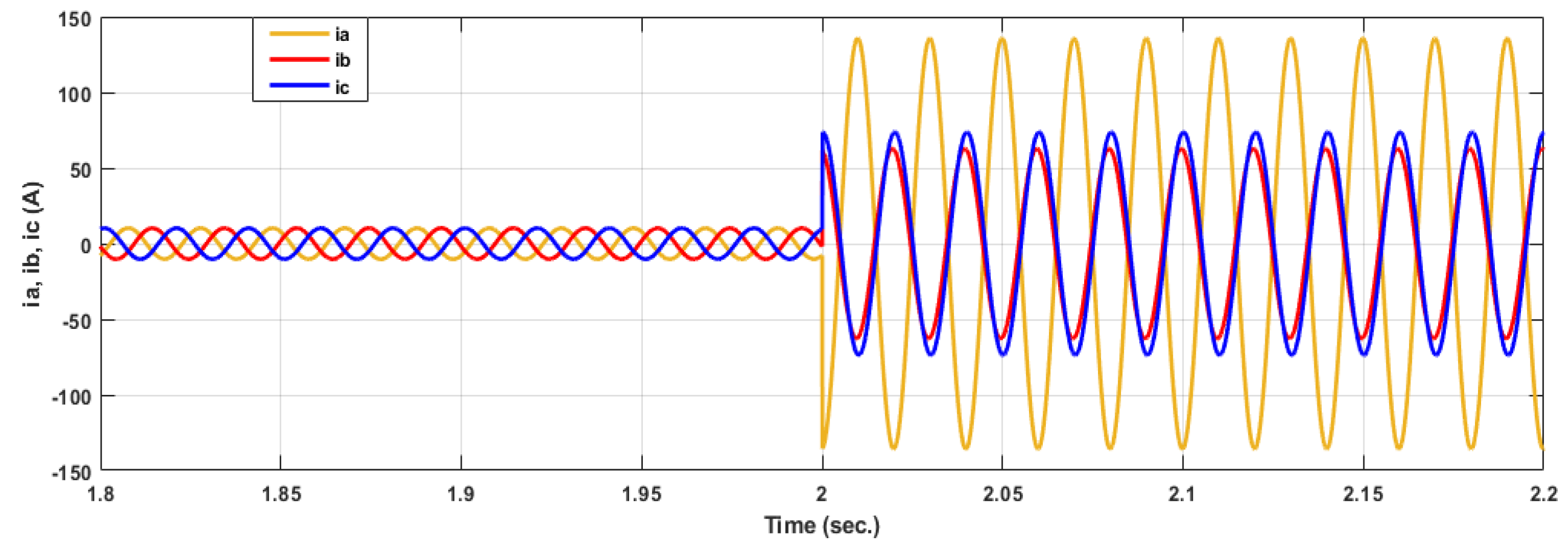
7. Simulation Results for Detection, Diagnosis and Activating the Trip Signal
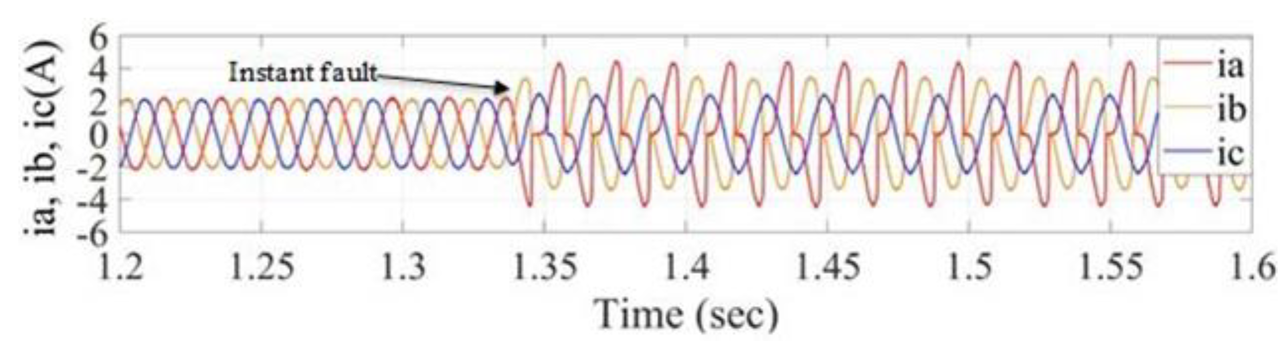
8. Experimental Results
- Induction motor: 1 hp, rated current 2 A, 3-phase 380 V;
- PC specifications: Core i5, RAM 4GB, hard SSD256GB, windows 7, and the proposed algorithm is implemented in MATLABE 2019B platform and when generating experimental results, no other programs are running on the PC;
- LABJACK UD-U3 is used to capture current samples from the power current lines of the induction motor.
9. Conclusions
Author Contributions
Funding
Conflicts of Interest
References
- Chavhan, K.B.; Ugale, R.T. Automated Test Bench for an Induction Motor using Lab VIEW. In Proceedings of the 1st IEEE International Conference on Power Electronics, Intelligent Control and Energy Systems, Delhi, India, 4–6 July 2016; pp. 1–6. [Google Scholar]
- Ramasamy, P.; Krishnasamy, V. SVPWM control strategy for a three-phase five level dual inverter fed open-end winding induction motor. ISA Trans. 2020, 102, 105–116. [Google Scholar] [CrossRef] [PubMed]
- Bacha, K.; Salem, S.B.; Chaari, A. An improved combination of Hilbert and Park transforms for fault detection and identification in three-phase induction motors. Int. J. Electr. Power Energy Syst. 2012, 43, 1006–1016. [Google Scholar] [CrossRef]
- Bouzid, M.B.K.; Champenois, G.; Tnani, S. Reliable stator fault detection based on the induction motor negative sequence current compensation. Int. J. Electr. Power Energy Syst. 2017, 95, 490–498. [Google Scholar] [CrossRef]
- Zaggout, M.; Ran, L. Detection of rotor electrical asymmetry in wind turbine doubly-fed induction generators. Renew. Power Gener. IET 2014, 8, 878–886. [Google Scholar] [CrossRef] [Green Version]
- He, W.; Zi, Y.; Chen, B.; Wu, F.; He, Z. Automatic Fault Feature Extraction of Mechanical Anomaly on Induction Motor Bearing Using Ensemble Super-Wavelet Transform. Mech. Syst. Signal Process. 2014, 54, 1–24. [Google Scholar] [CrossRef]
- Asad, B.; Vaimann, T.; Belahcen, A.; Kallaste, A.; Rassõlkin, A.; Iqbal, M.N. Broken rotor bar fault detection of the grid and inverter-fed induction motor by effective attenuation of the fundamental component. IET Electr. Power Appl. 2019, 13, 2005–2014. [Google Scholar] [CrossRef]
- Campos-Delgado, D.U.; Espinoza-Trejo, D.R.; Palacios, E. Fault-tolerant control in variable speed drives: A survey. IET Electr. Power Appl. 2008, 2, 121–134. [Google Scholar] [CrossRef]
- Sapena-Bano, A.; Martinez-Roman, J.; Riera-Guasp, M. Induction machine model with space harmonics for fault diagnosis based on the convolution theorem. Int. J. Electr. Power Energy Syst. 2018, 100, 463–481. [Google Scholar] [CrossRef]
- Mehala, N.; Dahiya, R. A Comparative Study of FFT, STFT and Wavelet Techniques for Induction Machine Fault Diagnostic Analysis. In Proceedings of the International Conference on Computational Intelligence, Haryana, India, 10–12 December 2008; pp. 203–206. [Google Scholar]
- Espinoza-Trejo, D.R.; Campos-Delgado, D.U.; Bossio, G.; Bárcenas, E.; Hernández-Díez, J.E.; Lugo-Cordero, L.F. Fault diagnosis scheme for open-circuit faults in field-oriented control induction motor drives. IET Power Electron. 2013, 6, 869–877. [Google Scholar] [CrossRef]
- Shi, P.; Chen, Z.; Vagapov, Y.; Davydova, A.; Lupin, S. Broken Bar Fault Diagnosis for Induction Machines Under Load Variation Condition Using Discrete Wavelet Transform. In Proceedings of the IEEE East-West Design & Test Symposium (EWDTS 2014), Kiev, Ukraine, 26–29 September 2014; Volume 1, pp. 1–4. [Google Scholar]
- Roshanfekr, R.; Jalilian, A. Wavelet-based index to discriminate between minor inter-turn short-circuit and resistive symmetrical faults in stator windings of doubly fed induction generators: A simulation study. IET Gener. Transm. Distrib. 2016, 10, 374–381. [Google Scholar] [CrossRef]
- Yahia, K. Induction motors airgap-eccentricity detection through the discrete wavelet transform of the apparent power signal under non-stationaryoperating conditions. ISA Trans. 2014, 53, 603–611. [Google Scholar] [CrossRef] [PubMed]
- Climente-alarcon, V.; Antonino-daviu, J.; Member, S. Induction Motor Diagnosis by Advanced Notch FIR Filters and the Wigner-Ville Distribution. IEEE Trans. Ind. Electron. 2014, 61, 4217–4227. [Google Scholar] [CrossRef] [Green Version]
- Ahamed, S.K.; Sarkar, A.; Mitra, M.; Sengupta, S. Induction Machine Stator Inter-Turn Short Circuit Fault. Innov. Syst. Des. Eng. 2014, 5, 75–82. [Google Scholar]
- Hammo, R. Faults Identification in Three-Phase Induction Motors Using Support Vector Machines. In Master of Technology Management Plan II Graduate Project; Bowling Green State University: Toledo, OH, USA, 2014. [Google Scholar]
- Lu, J.; Wang, P.; Duan, S.; Shi, L.; Han, L. Detection of Broken Rotor Bars Fault in Induction Motors by Using an Improved MUSIC and Least-Squares Amplitude Estimation. Math. Probl. Eng. 2018, 2018, 1–12. [Google Scholar] [CrossRef]
- Mejia-barron, A.; De Santiago-perez, J.J.; Granados-lieberman, D.; Amezquita-sanchez, J.P.; Valtierra-rodriguez, M. Shannon Entropy Index and a Fuzzy Logic System for the Assessment of Stator Winding Short-Circuit Faults in Induction Motors. Electronic 2019, 8, 90. [Google Scholar] [CrossRef] [Green Version]
- Bessam, B.; Menacer, A.; Boumehraz, M.; Cherif, H. DWT and Hilbert Transform for Broken Rotor Bar Fault Diagnosis in Induction Machine at Low Load. Energy Procedia 2015, 74, 1248–1257. [Google Scholar] [CrossRef] [Green Version]
- Nemec, M.; Ambrožič, V.; Fišer, R.; Nedeljković, D.; Drobnič, K. Induction Motor Broken Rotor Bar Detection Based on Rotor Flux Angle Monitoring. Energies 2019, 12, 794. [Google Scholar] [CrossRef] [Green Version]
- Zolfaghari, S.; Noor, S.; Mehrjou, M.R.; Marhaban, M.; Mariun, N. Broken Rotor Bar Fault Detection and Classification Using Wavelet Packet Signature Analysis Based on Fourier Transform and Multi-Layer Perceptron Neural Network. Appl. Sci. 2017, 8, 25. [Google Scholar] [CrossRef] [Green Version]
- Shao, H. Rolling bearing fault diagnosis using adaptive deep belief network with dual-tree complex wavelet packet. ISA Trans. 2017, 69, 187–201. [Google Scholar] [CrossRef]
- Keskes, H.; Brahama, A.; Lachiri, Z. Broken Rotor Bar Diagnosis in Induction Machines Through Stationary Wavelet Packet Transform and Multiclass Wavelet SVM. Electr. Power Syst. Res. 2013, 97, 151–157. [Google Scholar] [CrossRef]
- De Oliveira, H.M. Shannon and Renyi Entropy of Wavelets. Int. J. Math. Comput. Sci. 2015, 10, 1–5. [Google Scholar]
- Alsharabi, K.; Ibrahim, S.; Djemal, R.; Alsuwailem, A. A DWT-Entropy-ANN Based Architecture for Epilepsy Diagnosis Using EEG Signals. In Proceedings of the IEEE 2nd Interntioal Conference on Advanced Technologies for Signal and Smage Processing (ATSIP), Monastir, Tunisia, 21–23 March 2016; pp. 288–291. [Google Scholar]
- Hajihosseini, P. Process fault isolation based on transfer entropy algorithm. ISA Trans. 2014, 53, 230–240. [Google Scholar] [CrossRef] [PubMed]
- Mehta, S. Generalized Theory of Electrical Machines—A review. Int. J. Res. Sci. Innov. 2016, 3, 67–71. [Google Scholar]
- Leedy, A.W. Simulink/matlab Dynamic Induction Motor Model for Use as a Teaching and Research Tool. Int. J. Soft Comput. Eng. 2013, 3, 102–107. [Google Scholar]
- Bhatti, M.K.; Multan, T. Direct Quadrate (D-Q) Modeling of 3-Phase Induction Motor Using MatLab/Simulink. Can. J. Electr. Eng. 2012, 3, 237–243. [Google Scholar]
- Bachir, S.; Tnani, S.; Trigeassou, J.C.; Champenois, G. Diagnosis by Parameter Estimation of Stator and Rotor Faults Occurring in Induction Machines. IEEE Trans. Ind. Electron. 2006, 53, 963–973. [Google Scholar] [CrossRef]


| Wavelet Packet Transform (Used in the Proposed Method) | Stockwell Transform | Hilbert Transform |
|---|---|---|
| The wavelet packet transform generates a time and frequency representation of the signal at different scales. In this paper, the entropy power Energy of detailed WPT subbands of the induction motor is used to detect and classify the induction motor’s faults. Accurate fault detection in less than a second. | It splits the input signal into a number of sections. Each resulting section is first smoothed using a Gaussian filter. It then determines the frequency components of each section using Fourier transform. It provides a good time-frequency representation of the signal, but there is always a trade-off between its time and frequency accuracy. Moreover, its performance is limited to the size of the window. Authors reported good performance in terms of accuracy in the detection of the faults in a certain section of the motor, e.g., rotors. | It provides a representation of the signal in the same domain (frequency domain). Therefore, it does not provide information about the time of the fault occurrence. However, the focus of the presented research in this paper is on the speed and accuracy of fault detection and classification. |
| Authors | Used Techniques | Key Features |
|---|---|---|
| V.Climente-Alarcon et al. [15] | It uses Wigner–Ville distribution techniques to study rotor asymmetry and mixed eccentricities. | It splits the stator current into several time-frequency components. |
| Syed Kamruddin Ahamed et al. [16] | It uses DWT, Root Mean Square (RMS), and Power Density Entropy (PDE) index. | It analyses the window current signal in the steady-state operation of the motor. It determines the PDE of the high frequency wavelet of the motor current to detect faults in the stator winding of the induction motor. |
| R. Hammo [17] | It uses the Support Vector Machine (SVM), which is a learning-based method. | Results show that the application of SVM is alleviating some of the limitations of the Artificial Neural Network (ANN) based methods. Moreover, the SVM based method is more effective than ANN based method in detecting faults in terms of accuracy, where SVM uses the Radial Bases Function kernel. |
| J. Lu, P. Wang et al. [18] | It uses the MUltiple SIgnal Classification (MUSIC) technique and least-squares magnitude estimation to detect the frequency and amplitude of the faults. | Because the research of step travel produces lower efficiency, they proposed a method to improve MUSIC method using Niche Bare-bones Practical Swarm Optimization (NBPSO), which was used to detect broken bars in an induction motor. |
| A. Mejia-Barron et al. [19] | It uses both Shannon Entropy (SE) index and artificial intelligence fuzzy logic. | To diagnose faults in the stator of an induction motor, it applies brick-will band-pass filters at multiple levels on induction motor’s current signal and then calculates SE. |
| M. Nemec et al. [21] | It uses the frequency components of inductor motor’s current signal to diagnose faults in the rotor of the motor. | The existence of certain frequency components in the current signal of the induction motor indicates the fault in the motor. This method was applied to two different models of induction motor in MATLAB platform. |
| Proposed method | It uses wavelet packet transform and Shannon Entropy (SE) criteria | It uses performs 2 level WPT on induction motor current signal decomposes it into its wavelet subbands. It then determines EE of the fine WPT of the current as a feature to determine the status of the motor. If it was found faulty, it uses some empirically pre-determined thresholds to classify the fault. |
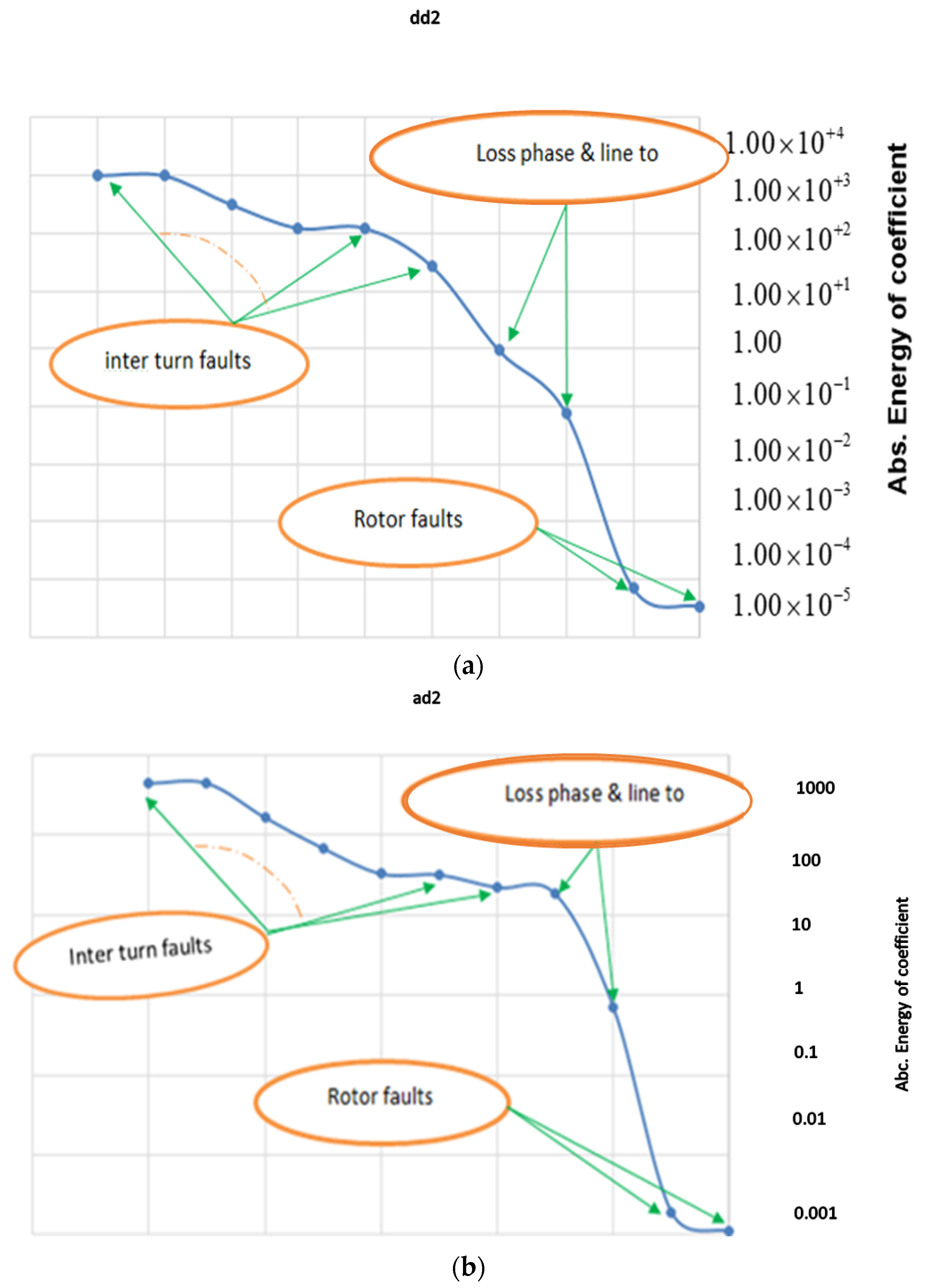
| Entropy | aa2 | ad2 | da2 | dd2 |
|---|---|---|---|---|
| Fault | ||||
| Healthy no load | −5.08 × 10⁵ | 7.41 × 10⁻⁵ | 4.30 × 10⁻⁴ | 8.37 × 10⁻⁵ |
| Healthy full load | −2.65 × 10⁶ | 2.78 × 10⁻⁴ | 1.30 × 10⁻³ | 2.85 × 10⁻⁴ |
| No load to full load healthy | −1.52 × 10⁷ | 0.0014 | 7.06 × 10⁻⁴ | 9.30 × 10⁻⁴ |
| 10% fault phase-b | −2.13 × 10⁶ | −0.5372 | 0.1605 | −3.4479 |
| 15% fault phase-b | −2.39 × 10⁶ | −6.6746 | 0.2593 | −20.04 |
| 25% fault phase-c | −3.28 × 10⁶ | −1.36 × 10² | 0.5235 | −3.14 × 10² |
| 25% fault phase-b | −3.29 × 10⁶ | −48.5216 | 0.4773 | −121.5733 |
| 50% fault phase-b | −7.83 × 10⁶ | −446.9326 | 0.2243 | −1.02 × 10³ |
| 50% phase-b and 10% phase-a | −8.08 × 10⁶ | −448.9294 | 0.2169 | −1.02 × 10³ |
| 25% phase-b and 10% phase-a | −3.43 × 10⁶ | −48.5382 | 0.4742 | −121.5034 |
| Loss phase-a | −1.48 × 10⁸ | −3.13 × 10³ | −7.15 | −6.64 × 10³ |
| Phase-c to ground | −3.16 × 10⁷ | −3.04 × 10³ | −8.88 | −6.65 × 10³ |
| Three-phase fault | −1.88 × 10⁷ | −17.2076 | 0.1901 | 0.5652 |
| Line-a to line-b fault | −3.91 × 10⁷ | 0.5976 | −2.6355 | −78.3431 |
| Line-a to line-b to ground fault | −1.55 × 10⁸ | −3.55 × 10⁴ | −1.63 × 10³ | −2.97 × 10⁴ |
| rotor broken 1-bar fault | −2.07 × 10⁶ | 0.0025 | 0.0704 | 6.44 × 10⁻⁴ |
| rotor broken 2-bars fault | −1.97 × 10⁶ | 3.08 × 10⁻⁴ | 0.068 | 2.69 × 10⁻⁴ |
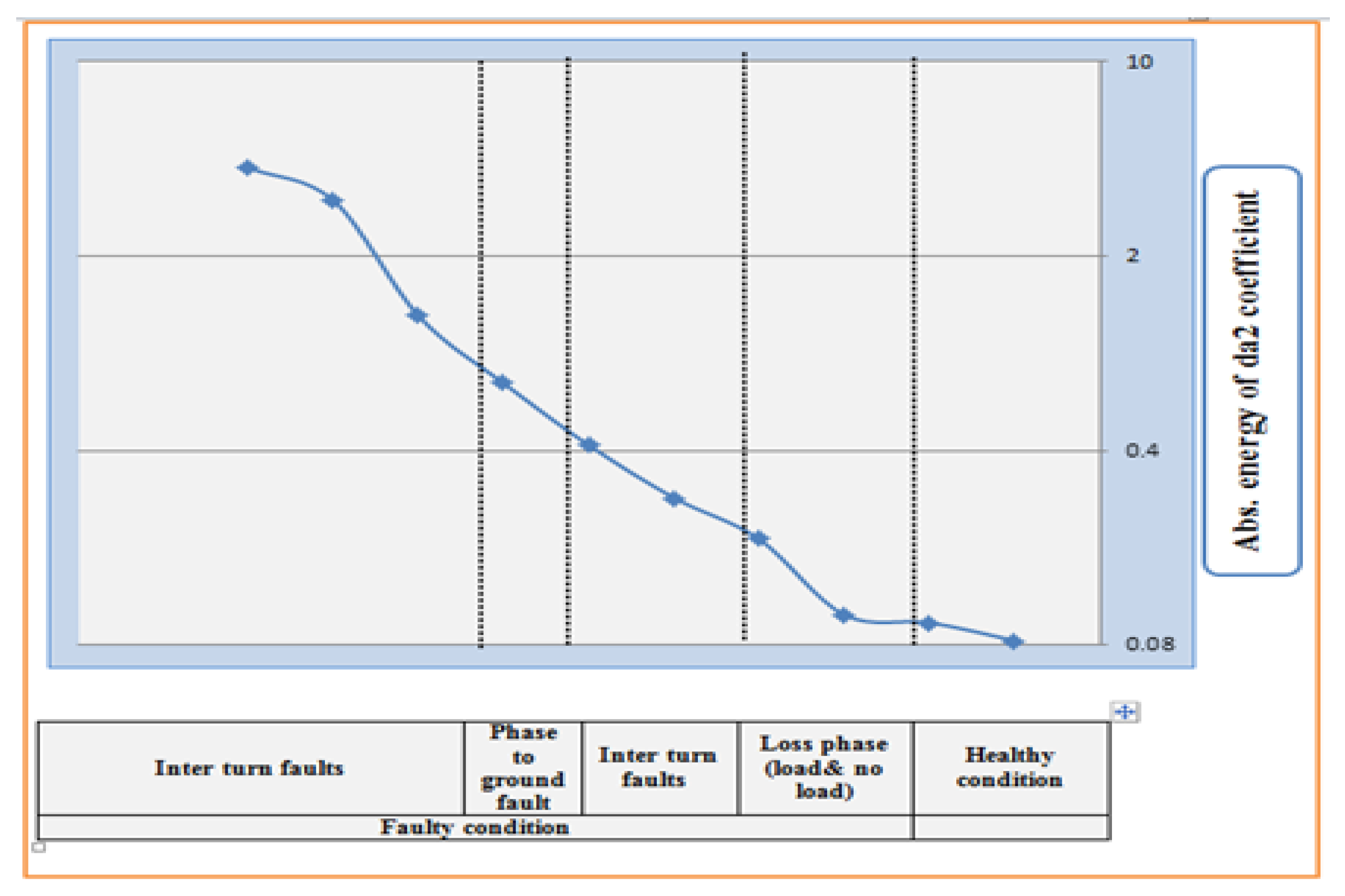
| Type of Fault | Entropy Power Threshold Value for WPT Subband | |
|---|---|---|
| ad2 | dd2 | |
| Broken one bar | 0.0011 | 3.43 × 10⁻⁵ |
| Broken two bars | 0.0019 | 7.11 × 10⁻⁵ |
| Line-a to line-b fault | 0.7054 | 0.0764 |
| Loss phase-a | 18.3 | 0.9424 |
| 10% inter turn fault phase-b | 21.9939 | 27.0078 |
| 25% ph. (b) and 10% ph. (a) inter turn fault | 31.7595 | 125.079 |
| 25% inter turn fault phase-b | 32.74 | 125.168 |
| 50% inter turn fault phase-b | 446.3932 | 1.02 × 10⁻³ |
| 25% ph. (b) and 10% ph. (a) inter turn fault | 446.611 | 1.02 × 10⁻³ |
| Motor Condition | WPT Subbands’ Entropy Power Energy | |||
|---|---|---|---|---|
| aa2 | ad2 | da2 | dd2 | |
| No-load healthy | −189.674 | 0.1468 | 0.0831 | 0.0995 |
| Loaded healthy | 781.5769 | 0.1725 | 0.0963 | 0.1224 |
| No-load 25% fault (b) | −1.13 × 10³ | 2.0998 | 0.4176 | 0.9368 |
| No-load 50% fault (c) | −2.56 × 10³ | 6.2222 | 3.1577 | 3.0059 |
| No-load with loss ph. (b) | −437.3249 | 0.5828 | 0.1027 | 0.1329 |
| Load condition with 10%fault (a) | −856.3741 | 0.6139 | 0.2703 | 0.4808 |
| Load condition with 25%fault (b) | −2.08 × 10³ | 4.9796 | 1.2152 | 2.0776 |
| Load condition with 50% fault (c) | −3.14 × 10³ | 11.3992 | 4.1454 | 5.4373 |
| Load condition with loss ph. (b) | −1.02 × 10³ | 0.7889 | 0.1922 | 0.2736 |
| Phase to ground fault | −1.27 × 10³ | 2.2173 | 0.6971 | 1.259 |
| Type of Fault | WPT Subbands’ Entropy Power Energy | |
|---|---|---|
| ad2 | dd2 | |
| 10% no load fault-a | 0.5016 | 0.2338 |
| 40% no load fault-b | 1.3107 | 1.1831 |
| 50% no load fault-c | 1.5828 | 1.3086 |
| Loss phase fault | 1.6341 | 0.8724 |
| Phase to ground | 1.7612 | 1.4303 |
| 50% loaded-c | 1.3877 | 0.9955 |
| Motor Condition | WPT Subbands’ Entropy Power Energy | |||
|---|---|---|---|---|
| aa2 | ad2 | da2 | dd2 | |
| No-load healthy | −3.8914 × 10⁵ | 1.7736 × 10⁻⁴ | 0.0191 | 1.2729 × 10⁻⁴ |
| Loaded healthy | −7.9257 × 10⁵ | 3.1433 × 10⁻⁴ | 0.0334 | 2.2519 × 10⁻⁴ |
| No-load 25% fault(b) | −2.9841 × 10⁷ | −2.2918 × 10⁴ | −1.5434 × 10³ | −256.4051 |
| No-load 50% fault(c) | −1.1857 × 10⁸ | −1.5737 × 10⁵ | −1.0024 × 10⁴ | −2.4242 × 10³ |
| No-load with loss phase(b) | −437.3249 | 0.5828 × 10⁷ | 0.1027 | 0.1329 × 10⁴ |
| Load condition with 10% fault (a) | −6.1115 × 10⁶ | −1.6653 × 10⁴ | −1.0147 × 10³ | −191.9537 |
| Load condition with 25% fault (b) | −3.0647 × 10⁷ | −1.1116 × 10⁴ | −735.9312 | −107.2747 |
| Load condition with 50% fault(c) | −1.1952 × 10⁸ | −1.7314 × 10⁵ | −1.1123 × 10⁴ | −2.6732 × 10³ |
| Load condition with loss phase (b) | −1.02 × 10³ | 0.7889 × 10⁷ | 0.1922 | 0.2736 × 10⁴ |
| Phase to ground fault | −1.27 × 10³ | 2.2173 × 10⁷ | 0.6971 | 1.259 × 10⁵ |
Publisher’s Note: MDPI stays neutral with regard to jurisdictional claims in published maps and institutional affiliations. |
© 2022 by the authors. Licensee MDPI, Basel, Switzerland. This article is an open access article distributed under the terms and conditions of the Creative Commons Attribution (CC BY) license (https://creativecommons.org/licenses/by/4.0/).
Share and Cite
Hussein, A.M.; Obed, A.A.; Zubo, R.H.A.; Al-Yasir, Y.I.A.; Saleh, A.L.; Fadhel, H.; Sheikh-Akbari, A.; Mokryani, G.; Abd-Alhameed, R.A. Detection and Diagnosis of Stator and Rotor Electrical Faults for Three-Phase Induction Motor via Wavelet Energy Approach. Electronics 2022, 11, 1253. https://doi.org/10.3390/electronics11081253
Hussein AM, Obed AA, Zubo RHA, Al-Yasir YIA, Saleh AL, Fadhel H, Sheikh-Akbari A, Mokryani G, Abd-Alhameed RA. Detection and Diagnosis of Stator and Rotor Electrical Faults for Three-Phase Induction Motor via Wavelet Energy Approach. Electronics. 2022; 11(8):1253. https://doi.org/10.3390/electronics11081253
Chicago/Turabian StyleHussein, Ameer M., Adel A. Obed, Rana H. A. Zubo, Yasir I. A. Al-Yasir, Ameer L. Saleh, Hussein Fadhel, Akbar Sheikh-Akbari, Geev Mokryani, and Raed A. Abd-Alhameed. 2022. "Detection and Diagnosis of Stator and Rotor Electrical Faults for Three-Phase Induction Motor via Wavelet Energy Approach" Electronics 11, no. 8: 1253. https://doi.org/10.3390/electronics11081253
APA StyleHussein, A. M., Obed, A. A., Zubo, R. H. A., Al-Yasir, Y. I. A., Saleh, A. L., Fadhel, H., Sheikh-Akbari, A., Mokryani, G., & Abd-Alhameed, R. A. (2022). Detection and Diagnosis of Stator and Rotor Electrical Faults for Three-Phase Induction Motor via Wavelet Energy Approach. Electronics, 11(8), 1253. https://doi.org/10.3390/electronics11081253