At the same time, we need to select several objects in order to study the key parameters. First, the circular transformer—as the most common transformer with central symmetrical structure—is used to study the key parameter selection and analysis methods of the transformers with a similar isotropic feature. Second, the square transformer—the most prominent feature is that the change of coupling coefficient with misalignment has directional anisotropy—is used to study the same type of transformer that has anisotropic characteristics. While the circular and square transformers are single-coil structures, the DD structure with double-coil layout is emphasized and the analysis methods of the key parameters of the double-coil transformer can then be derived. Since key parameters of both single-coil and double-coil layouts are investigated, the improved structure can be obtained through the analysis results of these three typical structures.
3.1. FEA of Circular Structure Transformer
One characteristic of a circular transformer is that the decrease in the coupling coefficient is always the same regardless of which direction is offset. In other words, it is isotropic. Therefore, in this section, the selection method of the key parameters of an isotropic transformer is proposed. In addition, as the most common type of transformer, the analysis of a circular transformer can meet the requirements of multi-objective design.
The circular coupling transformer is mainly composed of three parts: coil, ferrite, and shielding disk. For the shielding, the most popular design is to use the passive metal aluminum to make the shielding plate by inserting it into the back, which not only shields the high frequency space magnetic field, but also effectively reduces magnetic leakage and improves the efficiency and coupling performance.
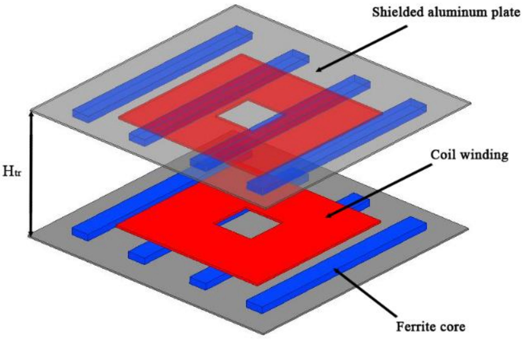
Due to the idiosyncrasies of object orientation, it is usually necessary to minimize the thickness of the coupling transformer’s vertical structure in order to satisfy the automotive WPT requirements. The physical model in 3-D is shown in
Figure 2. To facilitate the observation, the transparency of the structure in the secondary side is partly set to 50%.
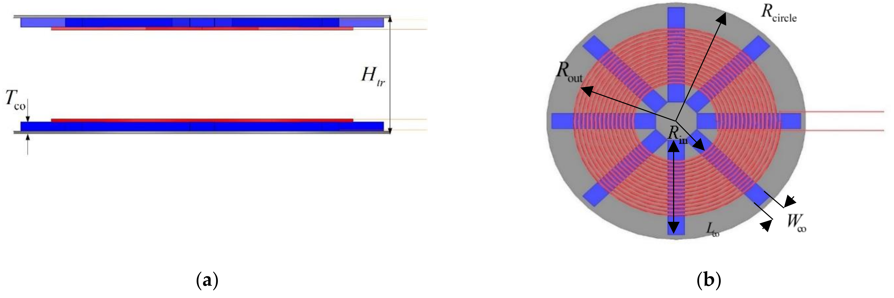
The dimensioning map of the circular transformer model in 2-D is shown in
Figure 3.
Htr is defined as the vertical distance between the lower surface of the primary coil shield and the upper surface of the secondary coil shield. Considering that the height of an average car from the ground is usually 150 mm–200 mm,
Htr is also designed based on this measurement.
Dtr is defined as the horizontal misalignment distance to the center point of the transformer.
Figure 3 is the 2-D dimensioning map of the primary side of the circular transformer. The transformer size is characterized as the radius of the disc,
Rcircle; inner diameter of the coil,
Rin; outer diameter of the coil,
Rout; the number of turns of the coil,
N; magnet length,
Lco; magnet width,
Wco; number of magnets,
Nco; and magnet thickness,
Tco.
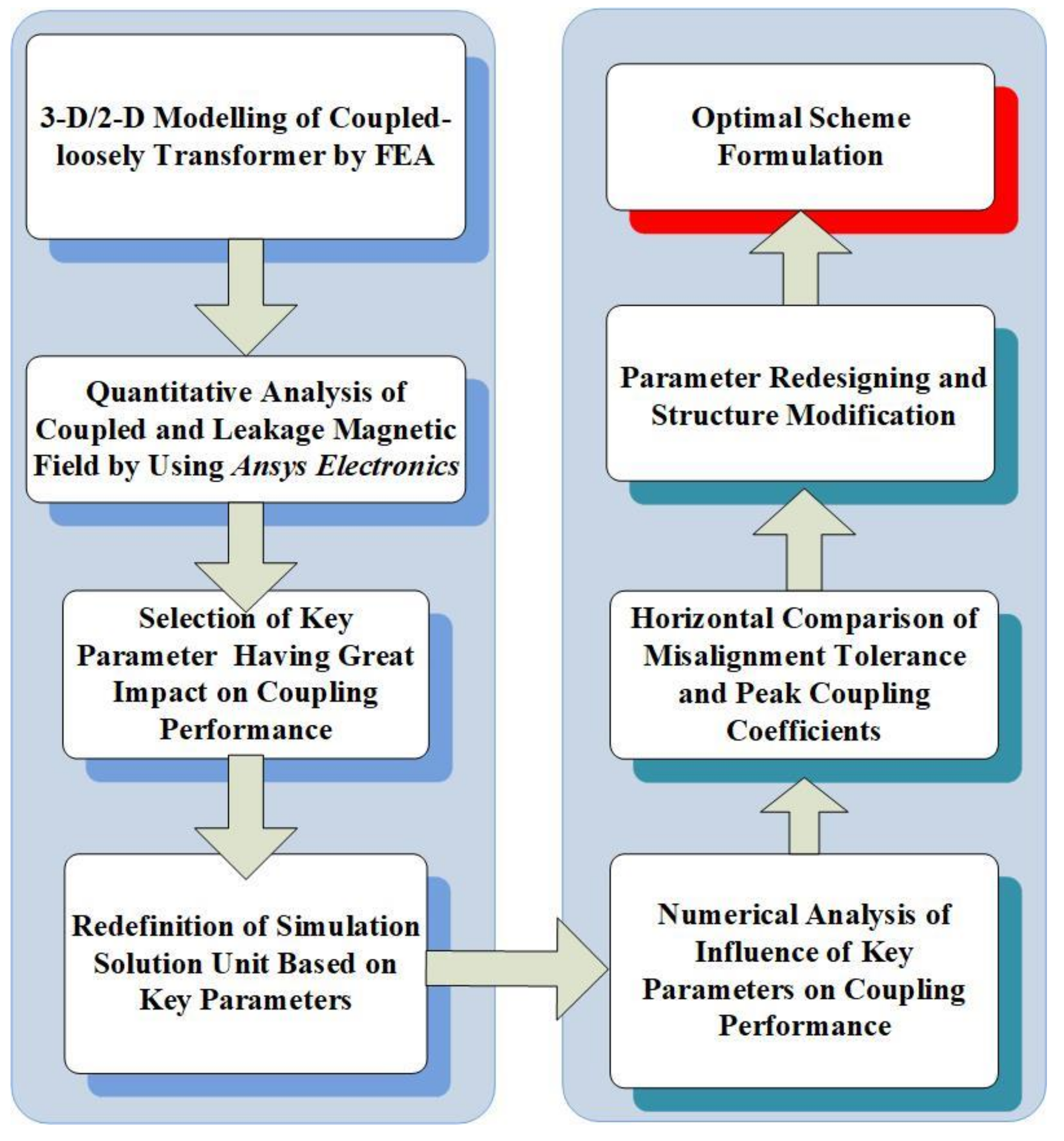
Based on this methodology,
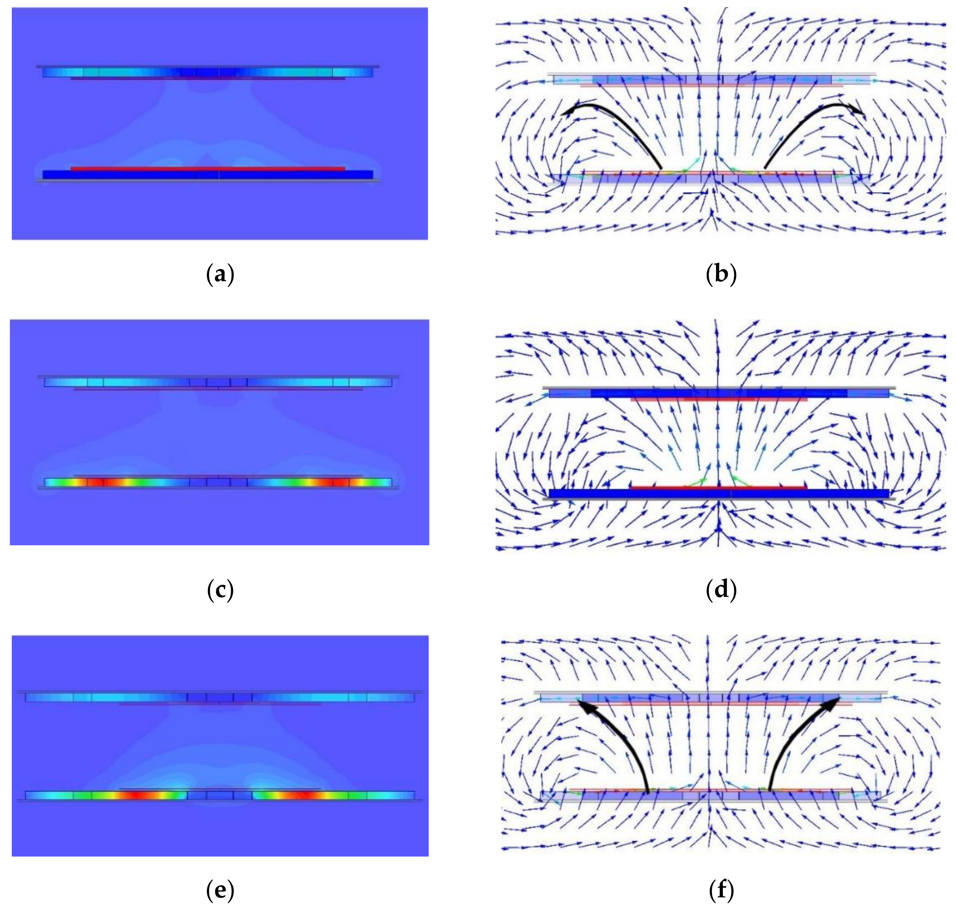
ANSYS Electronics is used to conduct quantitative analysis of the space magnetic field; analyze the relationship between the coupling performance, ferrite arrangement, and coil structure; and select the appropriate structural parameters. The characteristics of the magnetic field distribution under different diameter sizes of the coil obtained by FEA are shown in
Figure 4. It is observed that the leakage of the magnetic field accounts for most of the total; therefore, it is necessary to install a shielding device. A wider coil will lead to a shorter closing path of the divergent magnetic field outside of the coil and an increase in the magnetic leakage. It also causes the height of the magnetic field in the center of the coil and the mutual inductance magnetic field to increase simultaneously, which means that their ratio and coupling performance will be changed. This clearly demonstrates that both the inner and outer diameter of the coil play a dominant role in the distribution of the systematic space magnetic field. The FEA specification of key parameters is shown in
Table 1; the key parameter settings of FEA electromagnetic field simulation are shown in
Table 2.
The coil is wound with Leeds wire with five turns, each with a diameter of 4 mm. Thus, the original ferrite that was employed was 50 mm in length, 12 mm in thickness, and 32 mm in width. The width and thickness of the ferrite in the simulation are consistent with the table, but the length is an integer multiple of the original one. The experimental conclusions in the literature [
21] show that the overall size of the circular structure is determined by the spacing between the original and secondary sides. Generally, the overall size should be 2–3 times this spacing, and the diameter of the shielded aluminum plate should be at least 500 mm. According to the skin depth, the thickness of the shielded aluminum plate was designed to be 2 mm, and the length of the fixed ferrite was 200 mm. It was composed of four original ferrite blocks, which are slightly smaller than the overall structure’s size. To achieve the compromise between higher accuracy and a lower simulation time, a disk was selected to replace the Leeds line after many FEA tests. It was found that the error is less than 5% when the disk was defined as a solid with the same number of turns.
The key parameters affecting the coupling coefficient can be evaluated by analyzing the distribution characteristics of the space magnetic field. The external conditions were that the primary side was stimulated by 50 A and the secondary side excitation was 0 A. The magnetic field distribution of wide and narrow diameter coils in the YZ plane is demonstrated in
Figure 4. As shown in the figure, the excitation flows through the primary winding to produce a vertical upward magnetic field; this part punches through the secondary winding for the induction energy formation, which is the mutual inductance. However, due to the limited magnetic materials, the magnetic field had a partial divergence back to the original side after closure, which is the leakage field. When the inner diameter of the primary winding was different, the mutual inductance magnetic field with different height was formed, and the different coupling performance was subsequently obtained. From the comparative results shown in
Figure 4a,c, the larger coupling area of primary and secondary magnetic field was obtained with a wider coil inner diameter. It is also shown in
Figure 4b,d that the transformer with a wider coil inner diameter generated a higher mutual inductance magnetic-field height. Compared with the narrow inner diameter, the coupling magnetic field with a wide coil inner diameter accounted for a larger proportion than the leakage magnetic field. According to
Figure 4a,e, an increase in the outer diameter of the coil led to an increase in the leakage magnetic field due to a shorter closed path of the divergent magnetic field outside the coil. By observing the changes of magnetic field strength under different inner (outer) diameters, combined with electromagnetic theory, we concluded that the changes of inner (outer) diameters of the coil have a great influence on the coupling performance, which was then classified as the “key parameter”.
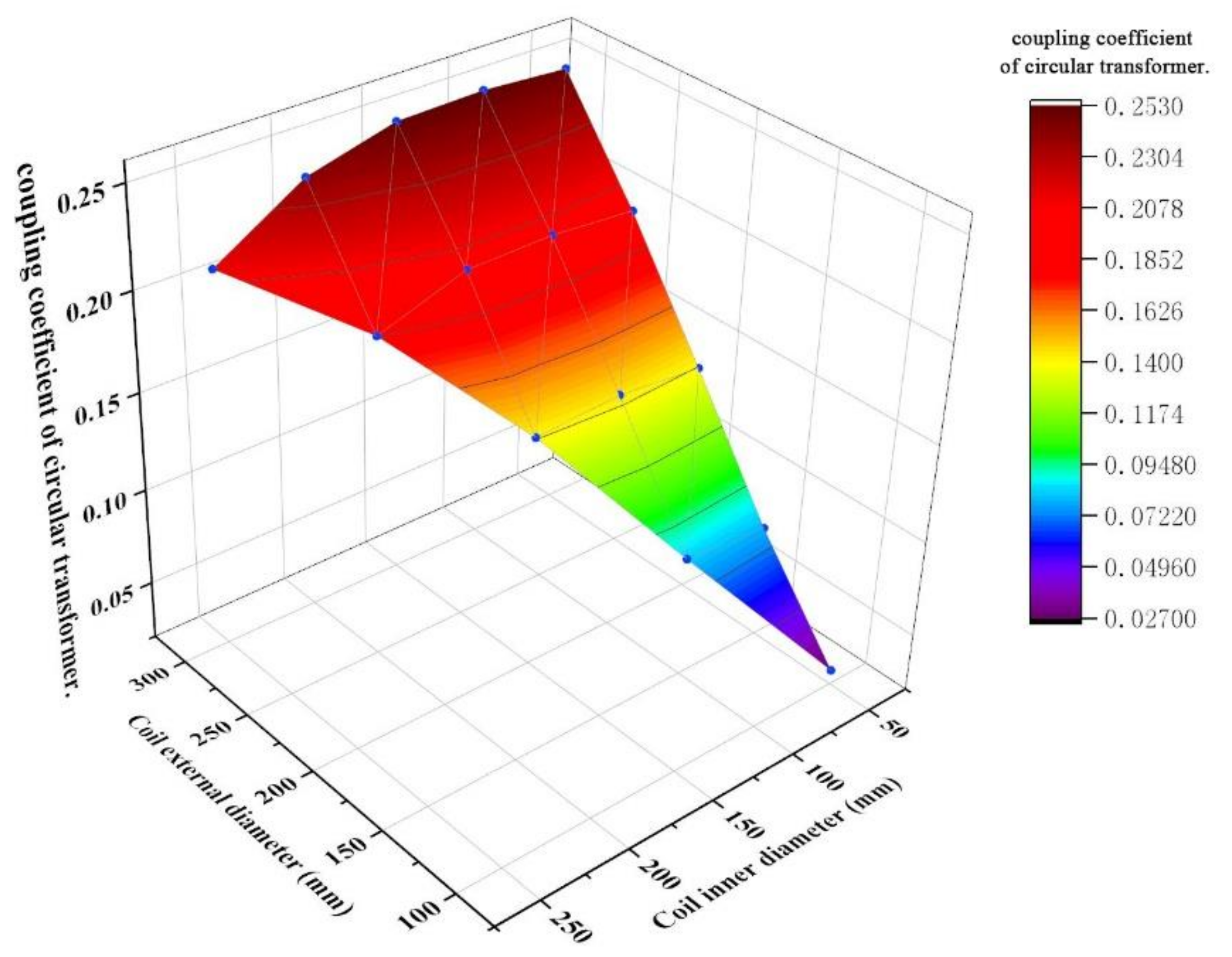
The coupling coefficients with 10–30 cm of the outer diameter and 5–25 cm of the inner diameter of the coil were calculated and shown in
Figure 5. It can be observed from the color scale diagram that a gradual increase in the inner diameter with the same outer diameter
Rout leads to a decrease in the coupling coefficient. In addition, the coupling coefficient increased with an increase in
Rout when
Rin was fixed. The change law is nonlinear. Both the mutual inductance and the leakage field were increased in this case. As
Rout is 30 cm and
Rin is set between 5 and 15 cm, the coupling coefficient was maintained at a high value. An increase in the ferrites number significantly increased the weight and cost as well. Too many ferrites resulted in the fragility of the rigid transformer structure; therefore, dramatically adding to the possibility of system instability. However, the coupling performance of the primary and secondary sides was enhanced due to the inherent feature of reducing the reluctance. In summary, considering the weight, structural strength, and production costs, the number and size of the ferrite were designed at appropriate values. Additionally, to facilitate the horizontal comparison of various structures, other transformers were adopted with the same total volume of ferrite.
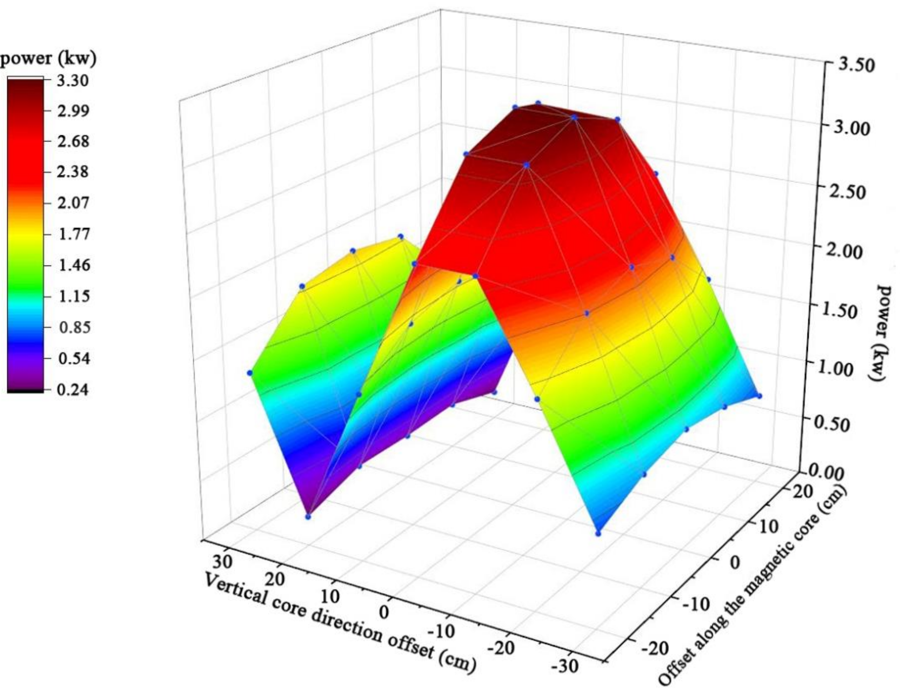
Horizontal and vertical misalignments between the primary and secondary sides of the transformer inevitably exist during WPT charging. It is necessary to simulate the change in the coupling coefficient under different misalignment conditions. We set the horizontal misalignment between 5 and 25 cm. Moreover, the distance between the receiving coil of the radio transmission device in the car chassis and the ground had a close relationship with the car load. The distance between the chassis and the ground gradually decreased with an increase in the vehicle’s weight. Therefore, the vertical misalignment size of the original auxiliary coil may decrease, and the vertical of misalignment can be restrained within 10 cm–30 cm. The horizontal and vertical misalignments are the key parameters here.
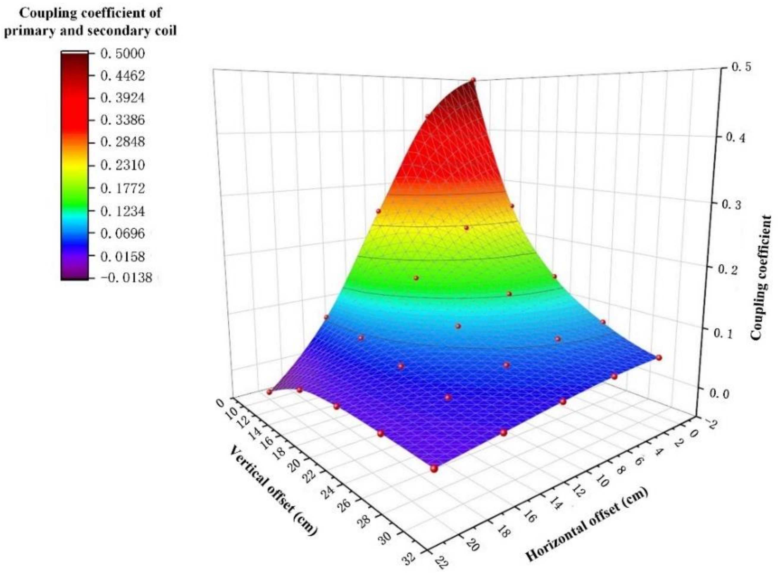
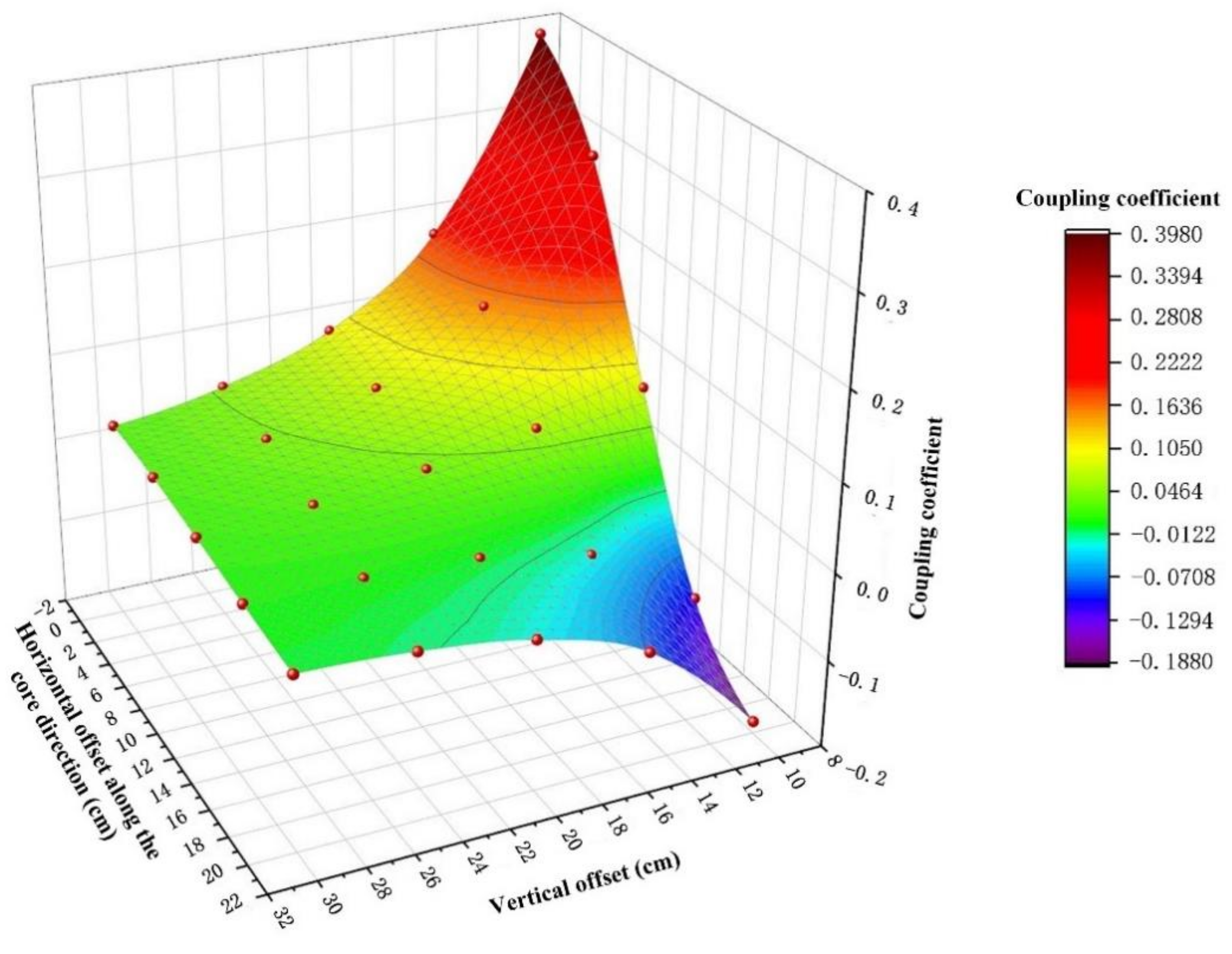
The FEA results are shown in
Figure 6. As depicted in the figure, the maximum coupling coefficient appears when the outer diameter is 30 cm and inner diameter is 5 cm. By keeping this size fixed, the coupling coefficient changed with the vertical offset varying between 10 and 30 cm and the horizontal offset changed between 0 and 20 cm. These changes were investigated and are graphically displayed in
Figure 6. The coupling coefficient decreased gradually with an increase in the horizontal misalignment
Dtr under the fixed vertical misalignment
Htr. The coupling coefficient approached zero and the transformer could not realize energy transmission when
Dtr increased to 20 cm. The results also illustrate that when
Htr is less than 20 cm, the coupling coefficient can be kept at a high value. With an increase in the air-gap, the coupling coefficient decreased gradually. The coupling coefficient was 0.0799 when
Htr increased to 25 cm, and the transmission efficiency was quite low. The coupling coefficient was at a high level when
Htr was within 10 cm–15 cm and
Dtr was limited between 0 cm and 10 cm, but it decreased rapidly and the misalignment tolerance was poor.
The number of ferrites, the structural stability, and the size combination of different inner and outer diameters of the coil should be considered as the key parameters in the optimization of a circular transformer. In addition, the horizontal or vertical misalignment of the primary and secondary windings are also verified as key parameters through analysis of the graphical FEA results.
3.2. FEA of Rectangular Structure Transformer
In daily parking, wheel blockers are often used to prevent cars from moving in a forward direction and causing collisions. In this case, a rectangular structure (as shown in
Figure 7) was proposed [
21], where the arrangement direction of the ferrite is the same as the forward direction of the vehicle. Since the misalignment perpendicular to the ferrite direction has no obvious effect on the coupling coefficient, a transverse direction was arranged. The direction with an obvious coupling change used the wheel stopper to define the position. Therefore, the misalignment tolerance of the rectangular structure is better than the circular structure in a daily parking situation. In contrast to the circular transformer, the attenuation of the coupling coefficient of a square transformer in different directions is anisotropic. The purpose of selecting it as the goal of our analysis was to study whether the key parameters of anisotropic transformers are the same as those of an isotropic transformer.
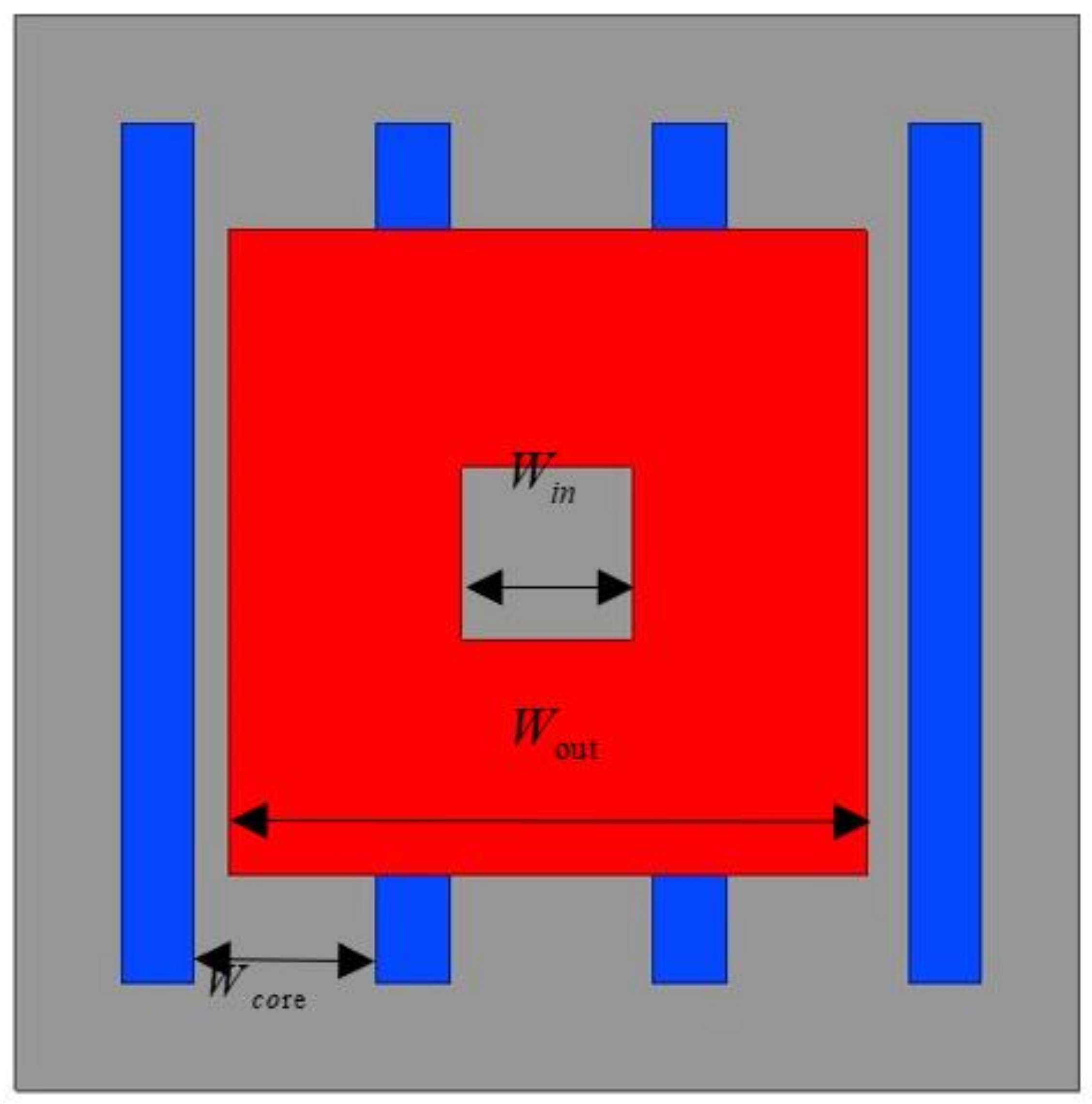
The rectangular structure transformer is mainly composed of shielded aluminum plate, ferrite, and coil. In order to match the placement of ferrite, the coil was wound into a rectangular shape. The primary view of the transformer is shown in
Figure 8, where the ferrite is connected by eight pairs and spliced together four ferrites with twice the length, the same width, and the same height. The key geometric dimensions are specified as an inner diameter of the coil,
Win; an outer diameter of coil,
Wout (as shown in
Figure 8); a distance between the internal ferrite and centerline,
Dre; and ferrite spacing,
Wcore. Similarly,
Htr is defined as the vertical distance from the lower surface of the primary coil shielding to the upper surface of the secondary coil shielding device.
Dtr is the horizontal misalignment of the center point of the primary and secondary sides. The key parameters of the rectangular transformer are displayed in
Table 3.
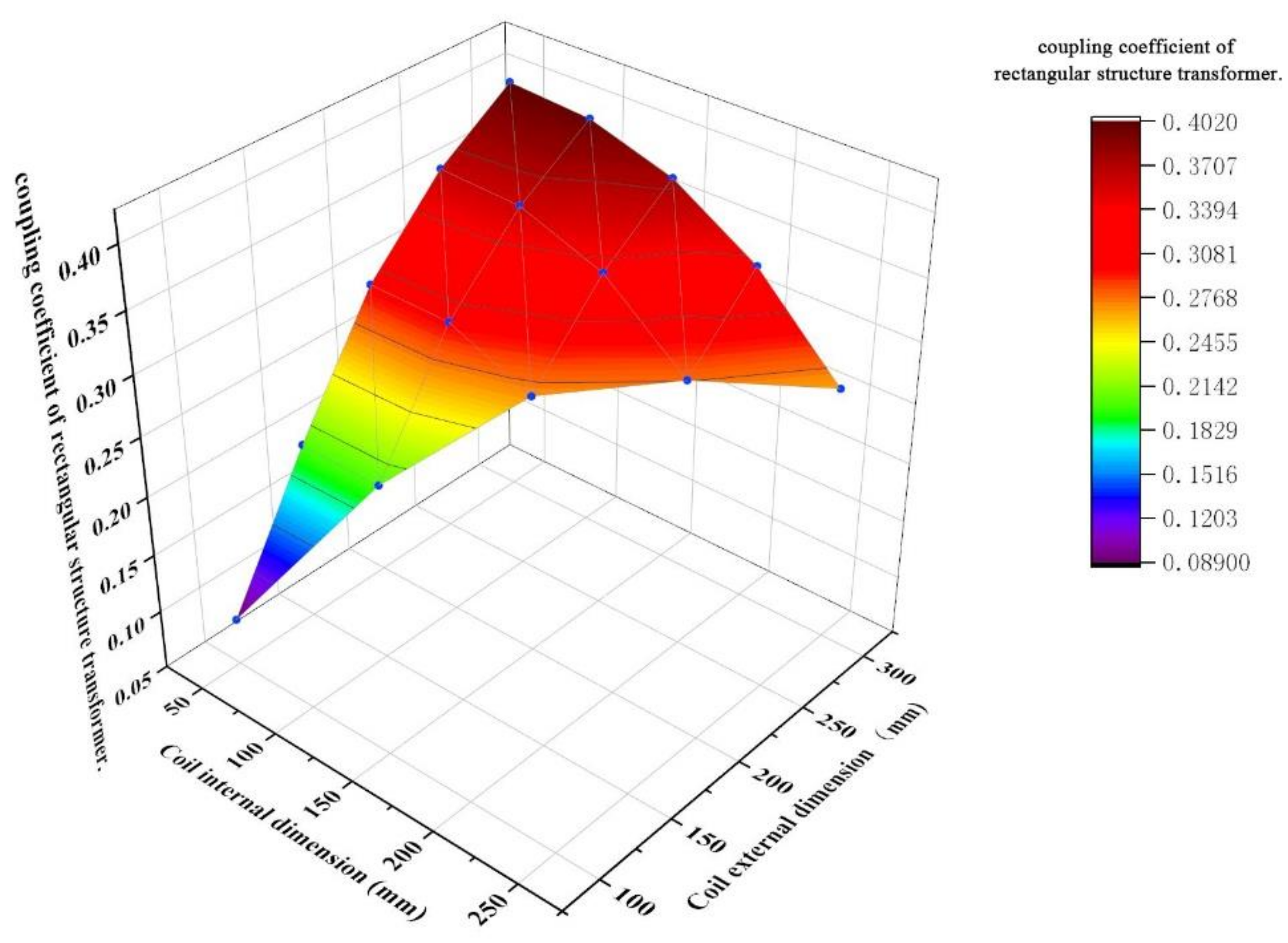
The coupling coefficient under different combinations of the inner diameter of the coil,
Win, (in the range of 5–25 cm) and the outer diameter,
Wout, (in the range of 10–30 cm), is graphically demonstrated in
Figure 9. Compared with the results in
Figure 6, we observed that the change law of coupling coefficients between the circular transformer and the rectangular transformer is basically the same when the inner and outer diameters change. The peak value appears at
Wout = 30 cm and when
Win is in the range of 5–15 cm. Therefore, analysis was implemented with
Wout = 30 cm and
Win = 10 cm in order to explore the impact of lateral misalignment and vertical distance on the coupling coefficient.
The layout of the rectangular transformer ferrite has clear directional characteristics. The horizontal misalignment is divided into two directions, the ferrite direction and vertical to the ferrite direction. The transformer vertical misalignment was initially defined as 10–30 cm.
Figure 10 shows the change law of the coupling coefficient with ferrite direction misalignment. A zero-coupling point appeared when the misalignment reached 15 cm. While it increased to 20 cm, the coupling was zero regardless of how the vertical misalignment changed. Therefore, the occurrence of the zero-coupling point was mainly related to the horizontal misalignment, instead of the vertical one. The changes of the coupling coefficient with misalignment perpendicular to ferrite direction are shown in
Figure 11. By comparing
Figure 10 and
Figure 11, we found that coupling coefficient decreased to about 40% when the misalignment vertical to the ferrite direction was added from 0 to 20 cm, while there was almost no zero-coupling point when the misalignment along the ferrite direction was increasing. Obviously, the decrease in vertical misalignment had a remarkable effect on the improvement of the coupling coefficient.
3.3. FEA of DD Structure Transformer
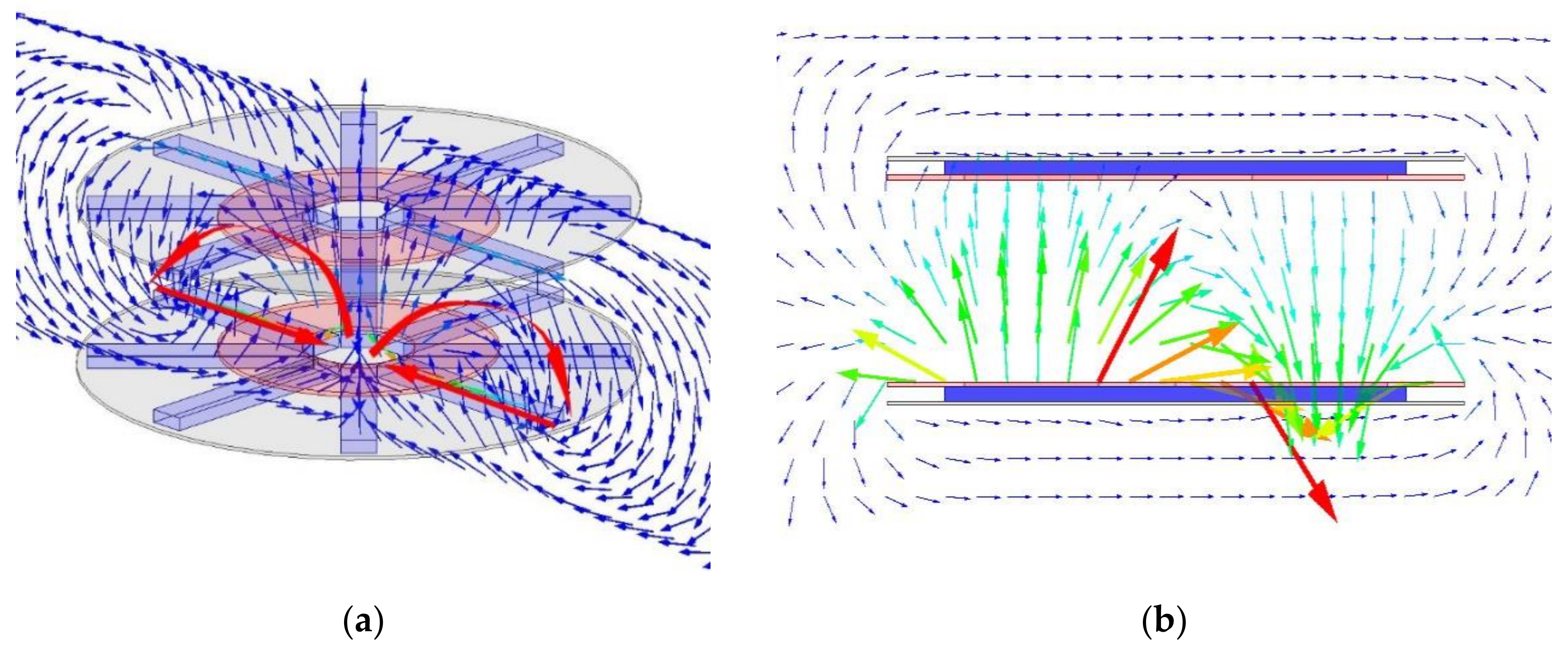
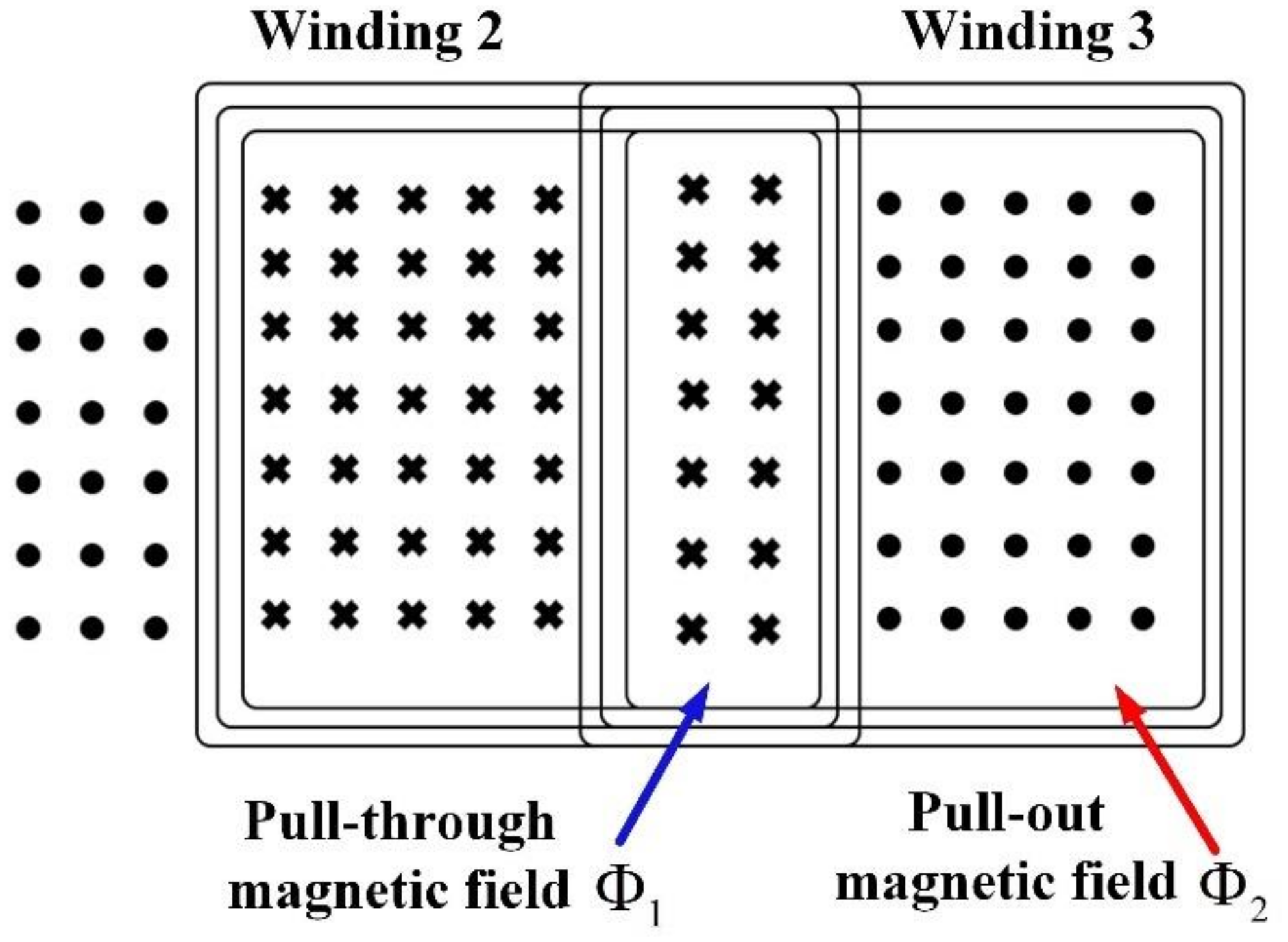
The analysis of a DD structure transformer studied the changes in the selection of key parameters of the double-coil layout. Both circular and rectangular transformers have single-sided and single-winding structure. For the single-winding, the inner circle of the transmitting coil emits a magnetic field, which passes through the secondary winding and returns to the ferrite at the back of the transmitting coil through the solution domain, thus forming a closed-loop magnetic field, as shown in
Figure 12a. While in the single-sided double-winding structure [
5], the magnetic field forms a closed loop with the magnetic field centered in the middle line of the two coils, as shown in
Figure 12b. The coupling performance of the primary and secondary sides was determined by the vertical height of magnetic field under a certain horizontal misalignment,
Dtr, condition. The magnetic field height and transmission efficiency of single-sided double-winding transformer were higher than that of a single-sided single winding with the same size and ferrite number. Therefore, a single-sided double-winding structure can provide more misalignment tolerance rate for transformer design and improve the efficiency and system stability.
The currents in the two coils were in opposite directions, and the ferrites on the back of the coils were aligned horizontally, as shown in
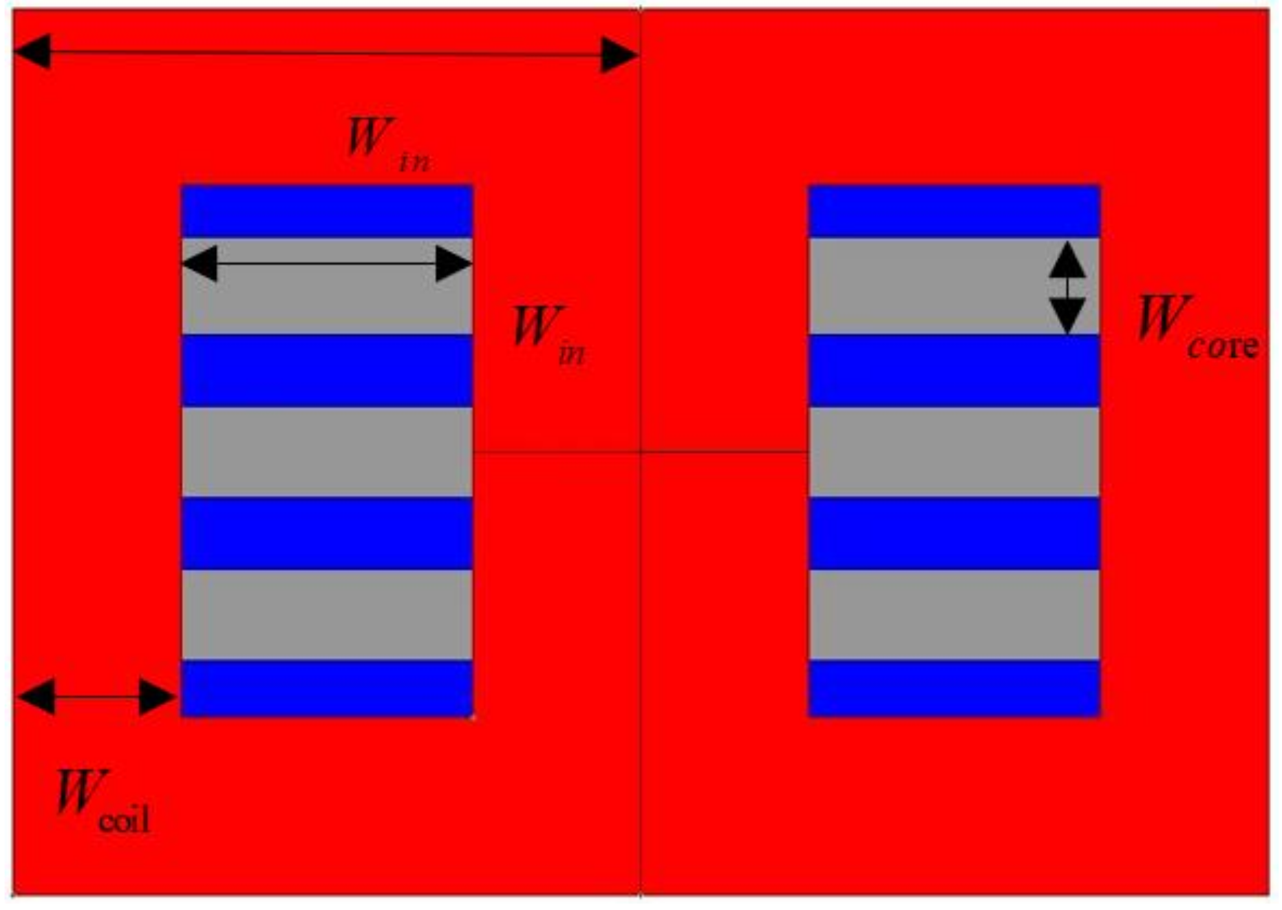
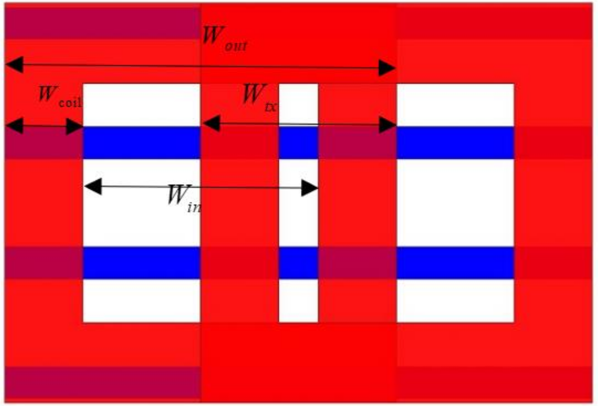
Figure 13. According to the FEA results of rectangular transformer, the coupling coefficient of DD structure also attenuated less with the misalignment vertical to ferrite direction. The key geometric parameters of DD structure are addressed in
Figure 14, including the outer diameter of coil,
Win; coil width,
Wcoil; inner diameter of coil,
Win; and distance between internal ferrite and centerline,
Dre. Similarly,
Wcore is defined as the vertical distance between the lower surface of the primary coil and the upper surface of the secondary coil of the shielding device.
Dtr is the horizontal misalignment of the center point of the primary and secondary sides. In order to produce a fair contrast with the single-sided single-winding, the parameters were specified as the overall width of the coil: 400 mm; the length: 600 mm; and the ferrite spacing: 40 mm. Considering the complex structure had a number of parameter combinations, the key parameters needed to be discovered. Obviously, the inner and outer diameter of the coil were key parameters and they need to be considered initially. The other key parameters of the DD transformer are listed in
Table 4.
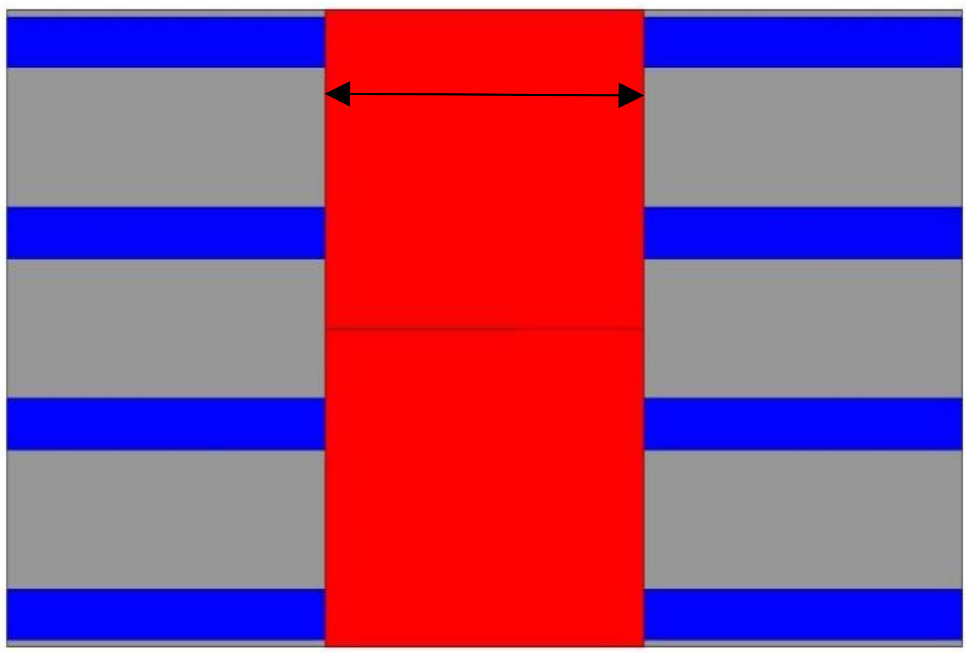
Due to the special structure of the DD transformer coil, the coil width cannot be unchanged when the outer and inner diameter of the coil are changed simultaneously. Therefore, the outer diameter and the width of the coil were taken as independent variables in order to investigate the changes of the coupling coefficient. The FEA parameters are shown in
Table 5. After the FEA-aided analysis, the inner and outer diameters of the coil were controlled with less constraints under the same coil width.
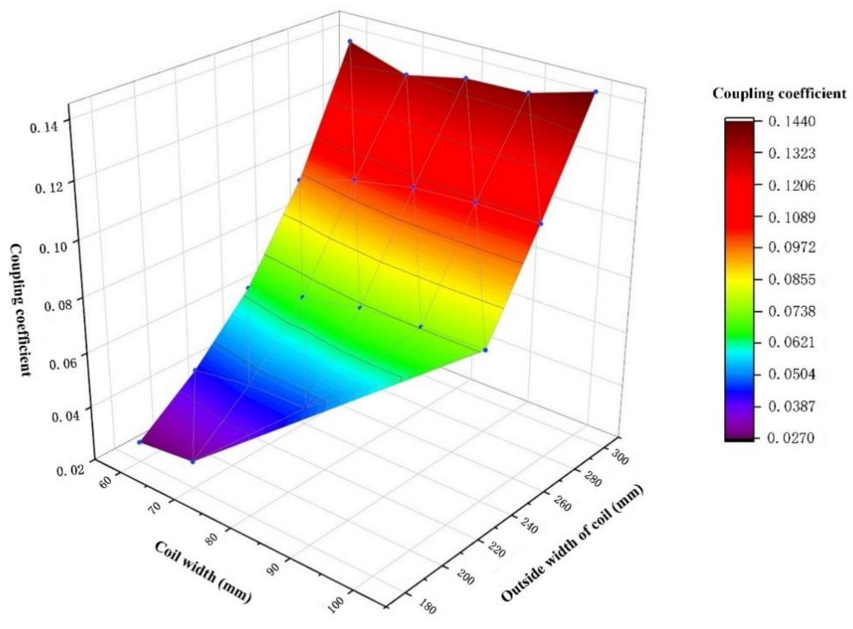
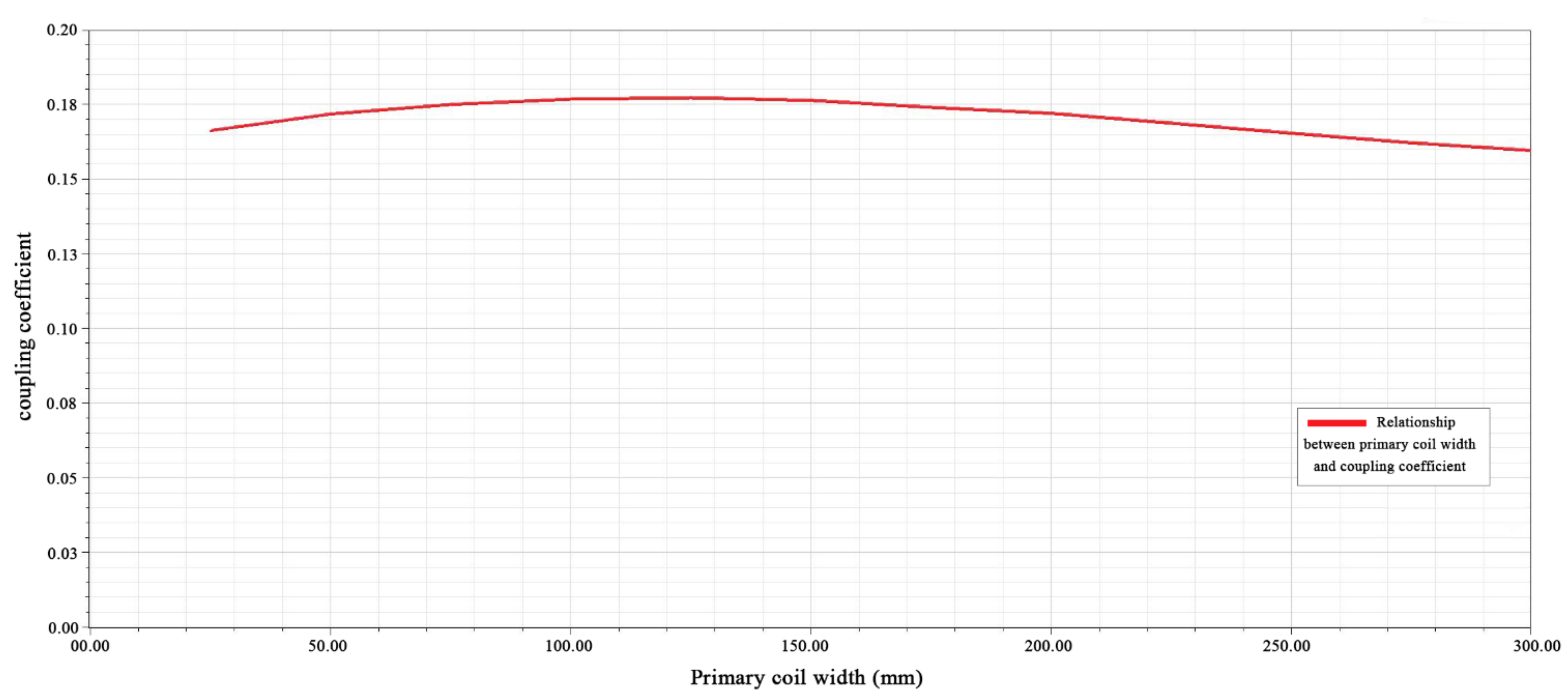
The simulation results with the same outer diameter of the coil
Wout are shown in
Figure 15. In this case, when the coil width
Wcoil increased from 60 mm to 70 mm, the coupling coefficient decreased. When
Wcoil climbed to more than 70 mm, the coupling coefficient decreased with the increase in
Wcoil. The reason is that the fixed ferrite spacing caused the coupling to decrease as the
Wcoil value increased. When
Wcoil was fixed, the coupling coefficient increased with the increase in
Wout. The best coupling performance appeared at
Wout = 300 mm and
Wcoil = 100 mm.
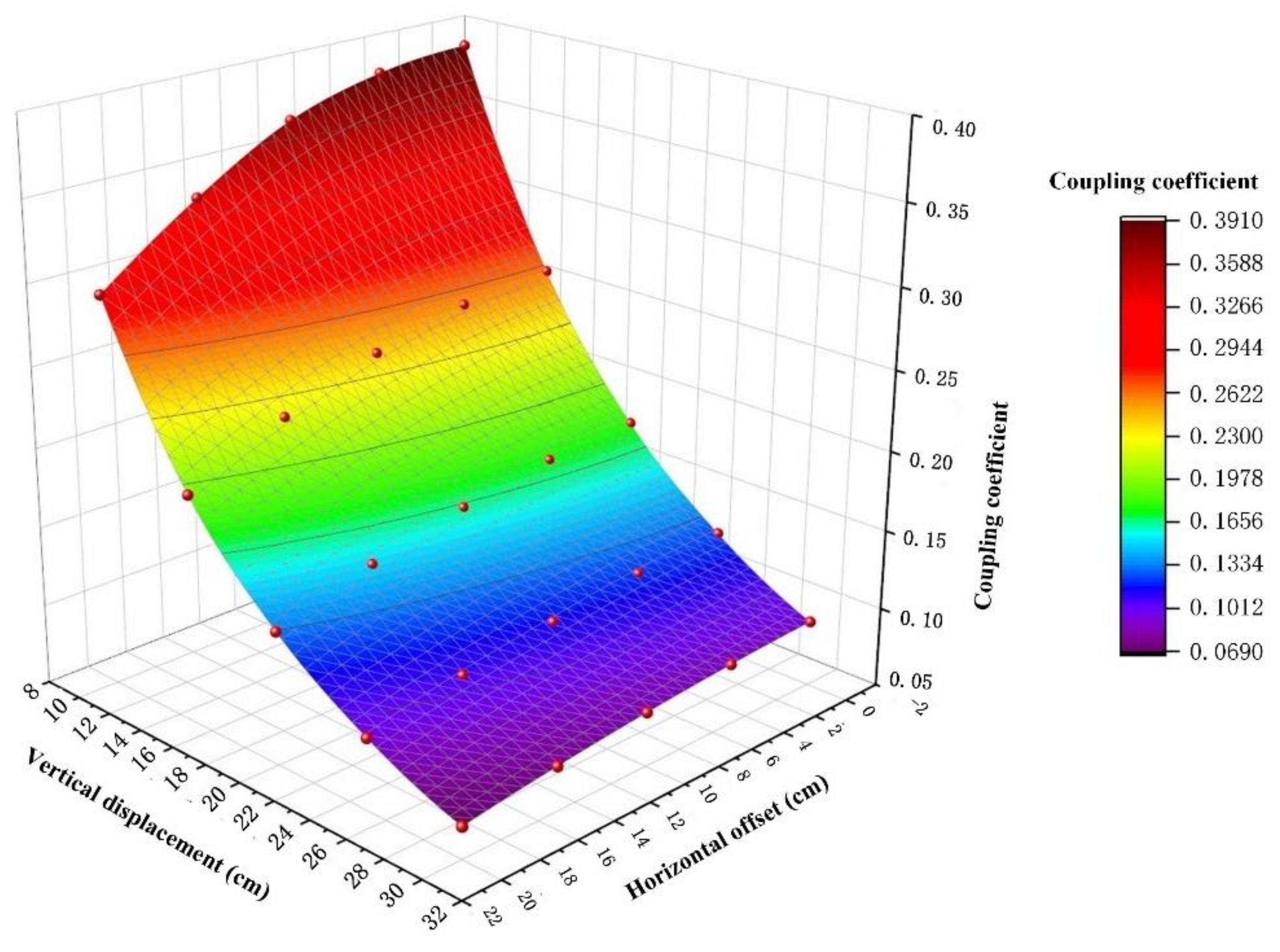
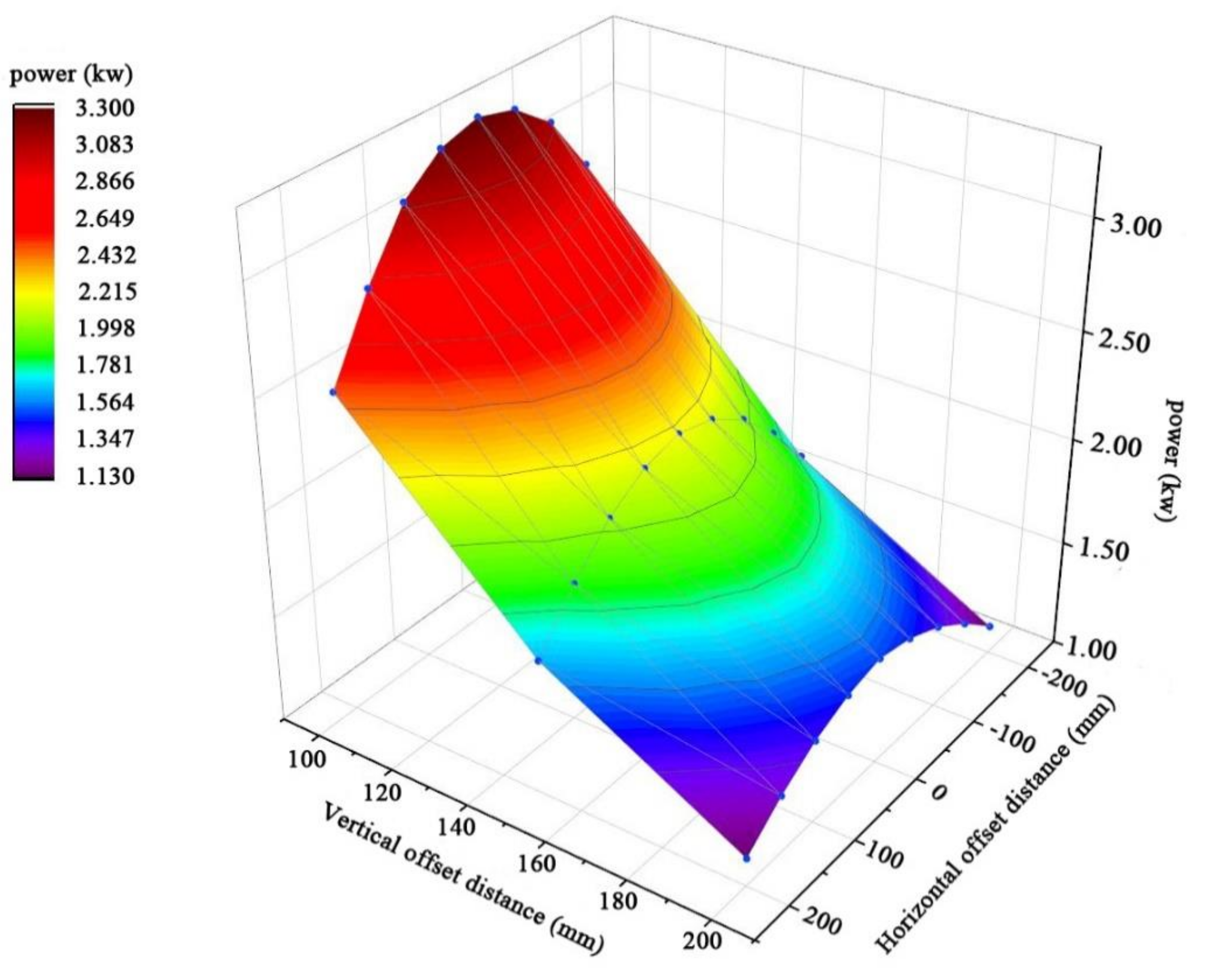
FEA was used to investigate the coupling coefficient variation under different misalignment conditions by selecting
Wout = 30 cm and
Wcoil = 10 cm. Since the DD and square structure transformers were applied in similar scenarios, only the influence of the misalignment perpendicular to the ferrite direction of the coupling coefficient needed to be explored. The horizontal misalignment of the coil vertical to the ferrite direction is defined as
Dtr and its variation range is 0–20 cm.
Htr is the vertical distance from the lower surface of the primary side coil to the upper surface of the shielding device in the secondary side coil, which varied between 10 and30 cm. The FEA results are shown in
Figure 16. The maximum value of coupling coefficient was 0.488 when
Dtr = 0 cm and
Wcore = 10 cm. This value increased by 30% compared with the square structure with single-side single-winding under the same misalignment condition. When
Dtr was 5 cm and
Wcore was 10 cm, the coupling coefficient increased by 48.8% compared with the square transformer. We verified that the single-sided double-winding structure had a stronger misalignment tolerance and magnetic field intensity than the single-sided single winding. The system coupling coefficient
Wcore dropped faster in the range of 20–25 cm of vertical misalignment. As it exceeded 25 cm, the system coupling performance fell to a low level.
Based on the numerical statistical results of FEA, it is worth noting that the maximum coupling coefficient of the three structures that have been improved consistently appears when the two key parameters—the inner and outer diameters—account for about 20% and 60% of the whole dimension of transformers, respectively.


