Article

A Path-Planning Method for Wall Surface Inspection Robot Based on Improved Genetic Algorithm

1
School of Mechanical Engineering & Automation, Beihang University, Beijing 100191, China
2
Research Institute of Aero-Engine, Beihang University, Beijing 102206, China
3
Large Aircraft Advanced Training Center, Beihang University, Beijing 100191, China
*
Author to whom correspondence should be addressed.
Electronics 2022, 11(8), 1192; https://doi.org/10.3390/electronics11081192
Submission received: 2 March 2022 / Revised: 5 April 2022 / Accepted: 6 April 2022 / Published: 8 April 2022
(This article belongs to the Special Issue State-of-the-Art Artificial Intelligence Technology)

Abstract

:
A wall surface inspection robot mainly relies on the inertial measurement unit and global positioning system (GPS) signal during intelligent wall surface inspection. The robot may encounter incorrect positioning under a GPS-denied environment, easily triggering safety accidents. In order to obtain a path suitable for the safe work of the robot wall surface inspection robot in a GPS-denied environment, a global path-planning method for wall surface inspection robots was proposed based on the improved generic algorithm (GA). The influencing factor for GPS signal strength was introduced into the heuristic function in path planning for GA to address the aforementioned problem. Using the PSO algorithm, GA was initialized and the influencing term of GPS signal was introduced into the fitness degree function so as to achieve point-to-point path planning of vertical wall surface inspection robot. Path angle and probability of intersection and variation was taken into account for better path planning capability. Finally, the simulation experiments were performed. The generated path using the improved GA was found to avoid the blind area of the GPS signal. The algorithm proposed has a good performance with average convergence times of 35.9 times and an angle of 55.88° in simple environment. Contrary to the traditional GA and PSO algorithm, the method showed advantages in terms of the convergence rate, path quality, path angle change, and algorithm stability. The research presented in this article is meaningful and relatively sufficient. The simulation test is also quite convincing. The proposed method was proved to be effective in global path planning for a wall surface inspection robot.

1. Introduction

Specialized robots can serve humankind under a specific environment and operate independently via short-range or remote cooperative control. At present, specialized robots have been extensively applied in many domains, including military, healthcare, patrol inspection, accident rescue, pipeline detection, underwater exploration, counterterrorism, and explosion clearing [1]. Wall-climbing robots, as a kind of specialized robot, now play an increasingly important role in many special scenarios that can hardly be accomplished by humans, such as hull cleaning, bridge inspection, and wall cleaning. Path planning, an important branch in mobile robot research, aims to construct a collisionless optimal path from the starting point to the target point [2]. Path planning mainly includes global planning and local planning. This study aimed to lay research emphasis on the former.
The genetic algorithm (GA) is a search algorithm that imitates the evolution of a biotic population in nature toward high environment adaptivity under environmentally selective action. The GA is now extensively applied in combination optimization, automatic control, signal processing, and artificial intelligence. Overcoming global path-planning problems with GA has always been a research hotspot in the robot research field. Using the genetic algorithm for robot path planning can ensure the algorithm has good global search ability and robustness. In addition, this method performs well in complex environments, which is suitable for the environment appearing in this manuscript.
Technical advances allow wall surface inspection robots to gradually expand the operating environment to the surfaces of complex structures such as steel bridges, buildings, hulls, or even wind-power blades [3,4,5,6]. These environments lack positioning features and experience great fluctuations in angles on the wall surfaces. GPS, IMU, and odometers are usually used for robot positioning and navigation. Slips between the wheels of the wall surface inspection robots and the wall surface is common. The GPS signal strength is an issue that cannot be ignored for positioning and navigation of wall surface inspection robots. Wall surface inspection robots generally operate under a GPS-denied environment, where GPS signals have low precision or are lost due to the occlusion of complex structures. How to perform path programming under this environment has become a problem to be solved urgently.
Keeping in mind the aforementioned problems, a global path-planning method was proposed based on the improved GA. It aims to plan a safety path for wall surface inspection robots effectively. The main contributions of the paper are:
  • A raster map of the environment construction method was present. The motion area according to the level of the premeasured GPS strength was divided. The spatial map containing GPS signal was established by introducing the GPS signal strength information into the raster map.
  • Based on the environment condition and operating feature of the wall surface inspection robot, the GA was improved. The particle swarm optimization (PSO) algorithm was used to initialize the GA, aiming to avoid the local optimum and slow convergence caused by over-randomness in GA initialization. The fitness function was optimized by taking into account the changes in the GPS signal strength and path angle. Additionally, a new crossover and mutation probability update method was used to develop the performance of GA based on population fitness.
  • Using the raster map, the simulation experiment was performed for comparison so as to validate the feasibility and effectiveness of the proposed method.
The results show the method proposed in this paper performs better in global path planning for wall surface inspection robots. With average convergence times of 35.9 times and angle of 55.88°, the obtained path has a smaller angular variation compared with traditional GA and PSO.
This paper is organized as follows: The related artwork is introduced in Section 2. Section 3 contains the method to establish a map of the motion space with a GPS signal. In Section 4, traditional GA is improved in the initialization method, fitness function, and crossover and mutation probability. In Section 5, the traditional GA and PSO are used to compare with the improved GA in the simulation experiment. Finally, Section 6 presents the final conclusions.

2. Related Work

Global path planning solves the problems under known environmental information. There is a large volume of literature on global path planning, reflecting the central role of global path planning in mobile robot control. Many scholars have proposed various mature solutions for global path planning, such as the visual picture method, the Dijkstra algorithm, and A* algorithm developed on the basis of the Dijkstra algorithm [7,8,9]. As robots operate under an increasingly complex environment, these algorithms cannot well address the environment-matching problems. Many heuristic algorithms or hybrid algorithms, such as the ant colony algorithm [10,11,12], simulated annealing algorithm [13,14,15], and rapidly exploring random tree algorithm [16,17,18] have been developed in succession. In recent years, some new biological intelligence algorithms have been proposed [19,20,21,22,23,24,25], which greatly expands the alternative methods of path planning.
Using the genetic algorithm for global path planning, which is widely used nowadays, is one of the research hotspots. A large number of excellent related studies have emerged since it was proposed. Adem et al. introduced the mutation operator computing method on the basis of a traditional GA-based path-planning algorithm [26]. The method could examine all spare nodes around the mutation node. Both the solving efficiency and the success rate could be remarkably enhanced by this method. The firefly algorithm (FA) has a problem of getting easily trapped in local optimum. Zhang et al. introduced the selection, crossover, and mutation of GA into FA and achieved the goal of both precision and performance enhancement with FA to solve the aforementioned FA problem [27]. In order to address collaborative path-planning problems for unmanned aerial vehicles and unmanned ground vehicles under urban environments, Wu et al. proposed a mixed algorithm combining a distribution estimation algorithm and GA [28]. They confirmed the superiority of the proposed mixed algorithm to pure EDA and pure GA. Meanwhile, GA also exhibits a series of problems including over-randomness of population initialization, long convergence time, and easily falling into local optimum in actual applications.
In recent years, wall inspection robots have increasingly replaced manual work in dangerous scenarios. Previous scholars have made a lot of explorations regarding the path planning of wall surface inspection robots. They achieved great improvements in the evaluation mechanisms of paths so as to adapt to the environment. The simplest way is to adopt the path length as the sole criterion and select the shortest path as the optimal solution [29,30,31,32]. Despite the simplicity and easy handling, the shortest-path solution could hardly be used under a multi-constraint environment, thereby showing great limitations. Some scholars started from the perspective of energy for motion path planning of wall surface inspection robots in complex environments, selecting the optimal path via comprehensive evaluation of the consumed energy [33,34,35,36]. Meanwhile, some others introduced the penalty function for the selection of the optimal path [37,38,39]. However, these path-planning methods were realized on the condition of accurate robot positioning information. Additionally, the effect of GPS signal strength on robot positioning performance was not considered in actual path planning and they failed to meet the expectations.

3. Establishment of the Motion Space Map with GPS Signal

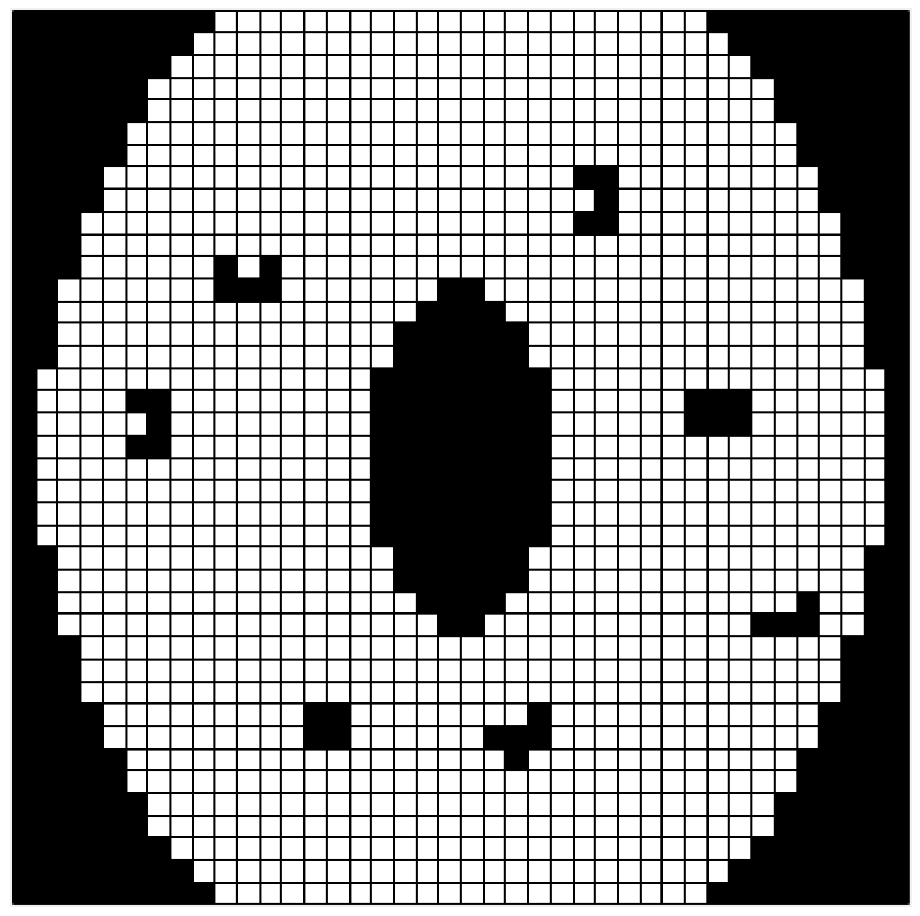
3.1. Establishment of Raster Map

Scholars have mainly established three maps for robot motion environment modeling during global path planning: raster map, topological map, and feature map [40]. The feature map is now rarely used. A topological map does not possess true physical size and only represents the relations among different positions and distances. On the contrary, a raster map well describes any forms of barriers and produces the binary information features for the convenience of computer storage and updates. Therefore, the raster mapping method, owing to its remarkable advantages, was selected for the environmental modeling of wall surface robots.
Figure 1 shows the operating area of a wall surface inspection robot: the surface of a steel tower on a large-span bridge with a Chinese-knot structure. The surface inspection robot needs to perform daily maintenance on the structure surface. By taking the middle area as an example, the robot’s inspection space was rasterized so as to form the raster map, as shown in Figure 2.
In the raster map, the robot travels in eight directions, which can be denoted by octrees. Two states exist for each grid, that is, each grid in the map is either occupied or free. As shown in Figure 2, the black grid represents the information of the barrier and the white grid represents the robot’s moveable area.

3.2. GPS Signal Strength Map

When performing global path planning under a conventional environment, the robot generally judges whether the space can be allowed to pass through or not according to the position information of the barriers under the actual environment. A wall surface inspection robot always merges GPS signal, IMU information and odometer information for positioning and navigation. As the moving wheels inevitably slip sometimes, GPS signal plays a crucial role in robot inspection. GPS signal is always unstable under a GPS-denied environment. Although no actual barriers exist that impede robot motion in the regions with weak GPS signal, the robot fails in positioning or shows undesirable positioning performance because of the loss of GPS signal. Accordingly, the navigation path may deviate or fail, finally leading to additional consumption in these regions. Therefore, the GPS signal can be divided into three levels according to its strength, as listed in Table 1.
The GPS signal strength map was formed by endowing each grid in the raster map with the signal strength so as to achieve a materialized representation of the GPS signal, as shown in Figure 3.

3.3. Map of Motion Space

Wall surface inspection robots generally perform an intelligent inspection on the surface of the steel tower bridge because of the existence of high-altitude shelters. Under the operating environment, actual barriers exist and GPS signal is weak. Assuming that U denotes the physical motion space of the robot (i.e., the whole surface of the steel tower bridge under inspection). R denotes real barrier space (i.e., some bulged materials on the surface of the steel bridge surface that the robot cannot overcome, such as large rivets). S denotes the GPS signal space (i.e., the GPS signal space covering the whole inspection surface). S Y denotes the passable subspace of the robot, which includes 0-level, 1-level, and 2-level signal regions, S Y = S 0 S 1 S 2 . S N denotes the impassable space of the robot (i.e., the three-level signal region, S N = S 3 ). The robot’s normally operating space, passable space, and obstacle space can be denoted as A normal = U R S 0 , A accessible = U R S Y , and A obstruct = R S N respectively.
Assuming that the path includes m path points and denotes each path point, the constraint condition for judging whether the path is passable can be written as:
P ( x ) = { 1   , { p ( x 1 ) , p ( x 2 ) , , p ( x m ) } A accessible 0   , e l s e .
The grid size was defined via horizontal projection of the robot and each grid was regarded as a unit point in path planning. According to the position data of the barriers in the motion space, GPS signal strength, position data and the grid properties could be uniformly described at the gray level. The grids corresponding to the space set A accessible were assigned with different gray levels in accordance with the strength level in GPS signal semantic map. For the convenience of calculation, the gray levels were set as four values (0, 1, 2, and 3) and mapped to the gray values (0–255). The maximum and the minimum gray levels in the mesh were 0 and 255, respectively, where A normal space set was located. For a grid with a size of n × m , the gray level of each grid in the grid set was described as:
G 0 = [ g 11 g 12 g 1 m g 21 g 22 g 2 m g n 1 g n 2 g n m ] .
In the gray level ranging from 0 to 255, the maximum value 255 and the minimum value 0 reflected white and black, respectively. To make the map represent the characteristics of the motion space more visually and enhance self-explanation and readability of the map, the gray-level matrix was negated as:
G 1 = [ 255 g 11 255 g 12 255 g 1 m 255 g 21 255 g 22 255 g 2 m 255 g n 1 255 g n 2 255 g n m ] .
G 1 and original raster maps were then superimposed. The grids marked as free in the original raster map were searched and replaced by the values at the corresponding positions in G 1 . Finally, the state space of the Chinese-knot motion space of the wall surface inspection robot was obtained, as shown in Figure 4. The figure contains both GPS strength information and actual barrier information. A darker color in the map represents higher cost that the wall surface inspection robot requires for moving in this area.

4. Improved Generic Algorithm

4.1. GA and PSO Algorithm

The GA was first proposed by Professor J. Holland from the University of Michigan in 1973 [41]. The GA implements genetic manipulation on each individual, including selection, crossover, and variation, by imitating the evolutionary process of an artificial population. It generates a new population with the male parent. It selects individuals with high fitness degrees as the operational objectives in the next iteration. The population is evolved/transformed during several generations in order to obtain a final population that contains individuals with the best possible quality for the problem at hand [42].
When considering the global path planning of the wall surface inspection robot, the GA always exhibits a series of problems, including blindness in initialization and being easily trapped into local optimum. Besides being time-consuming, the path quality can hardly be guaranteed. The GA needs to be further optimized according to the actual condition.
The PSO algorithm was first proposed by Dr. Eberhart and Dr. Kennedy in 1995 based on the research on bird flock preying behavior [43]. PSO tries to simulate the choreographed motion of swarms of birds as part of a socio-cognitive science [44]. Two attributes, velocity and position, were designed for imitating a bird in the flock in PSO. To be specific, velocity represented the moving speed and position represented the moving direction. Each particle represented a possible solution in the current optimization task. During the implementation of the PSO algorithm, each particle searches the individual optimal solution in the searching space and shares with each other so as to obtain the globally optimal solution. Next, each particle can adjust its velocity and position based on the individual optimal solution and the globally optimal solution. When a particle finds a better solution, all particles move close to it according to a certain rule.
The PSO algorithm for the path planning of wall surface inspection robots could achieve optimization without adjusting a large number of parameters. Despite easy operation and fast convergence, the PSO algorithm still showed some problems in the path planning of the wall surface inspection robot, such as premature convergence and being easily trapped into local extreme. In addition, unnecessary turns along the planned path and great deviation from the optimal solution existed. The consumed computation time also increased significantly with the increasing number of path control points.

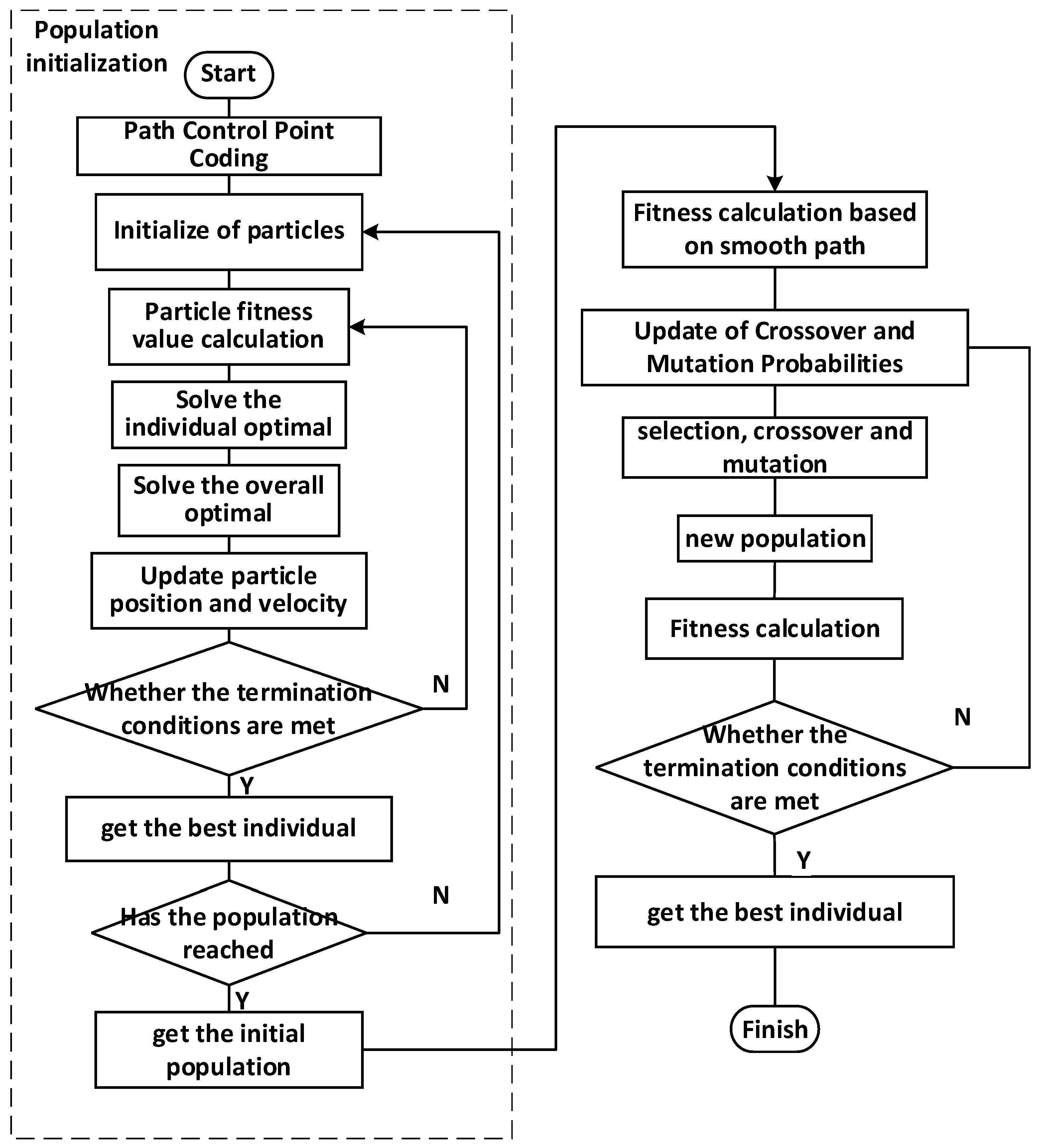
4.2. Robot Path-Planning Algorithm Based on the Combination of PSO Algorithm and GA

The ultimate goal of path planning was to obtain the optimal path within the established evaluation system. For the convenience of calculation, the coordinates of the path control points could be adopted as the coding basis.
For the kth population Q k including m individuals, the following expression could be obtained by Equation (4).
Q k = {   T 1 k ,   T 2 k ,   ,   T m k   } .
Assuming the existence of a segment of path T m k with n control points in the kth population and that the coordinates of the ith path point can be denoted as ( m x i k , m y i k ) , the codes are shown in Figure 5.
The selection was performed in accordance with the fitness degree F ( T m k ) . A larger F ( T m k ) was indicative of larger probability of selecting the individual T m k . The roulette method is generally adopted as the selection principle. The Euclidean distances between two adjacent points, denoted as d i i + 1 , were calculated in path planning and accumulated so as to obtain the total path length D ( T m k ) . The reciprocal of the total length was then calculated as the fitness degree. d i i + 1 , D ( T m k ) , and F ( T m k ) could be obtained by Equations (5)–(7), respectively.
d i i + 1 = ( m x i + 1 k m x i k ) 2 + ( m y i + 1 k m y i k ) 2 .
D ( T m k ) = i = 1 n d i i + 1 .
F ( T m k ) = 1 D ( T m k ) .

4.2.1. Algorithm Flow

The proposed algorithm could be implemented in the following steps.
Initialization: The raster map was established according to the surrounding environment and GPS signal strength, in which G denotes the maximum number of iterations, g denotes the current number of iterations, n denotes the initialized gene length (i.e., the path control point), m denotes the population number, γ 0 denotes the initial value of crossover possibility, ψ 0 denotes the initial value of mutation possibility, and ρ denotes the proportion of male parents in the evolution. The initial populations were generated using the PSO algorithm, with m global paths from the starting point to the end point.
Fitness Calculation: The fitness functions of the initial populations were calculated, and all paths among the initial path set were evaluated. The cubic spline interpolation path smoothing method was introduced for generating the smoothed curves among the control points to avoid the impact of the robot moving path on the system and ensure stable robot operation. Both the path distance and angles of different points in the curves were calculated. The initial paths were then ranked according to the fitness function. The maximum fitness degree was adopted as the fitness degree of all paths in the current generation.
Crossover and Variation: The crossover probability and variation probability of each point between the current generation of paths according to the fitness function were calculated. The crossover probability γ and the mutation probability ψ were updated.
Selection: The path ranking the top in terms of fitness degree was selected according to the proportion of elder generation as the male parent in the next path. Crossover and mutation were performed according to the path control points so as to generate the next generation of new path sets.
Judge Termination Conditions: The fitness degree of the next path set was calculated; the path in the set with the highest fitness degree was selected as the fitness degree of the new path set. Whether the terminal condition could be satisfied was judged. If yes, the path with the highest fitness degree was selected as the final result; otherwise, Step 3 was repeated.
Obtain Best Path: The optimal path was obtained and the final path point was output using the cubic spline interpolation results. The program was ended.
Figure 6 shows the detailed flow chart:

4.2.2. Initialization Method

Population initialization obtains the original population with the algorithm. Original GA randomly generates a certain number of solutions in the solution space as the initialized results, during which no heuristic function is used. The solving process is too random and blind. Accordingly, many poor solutions exist in the original population and the proportion of high-quality genes is low, requiring a long convergence time in subsequent evolution. Overall, the solving process is easily trapped into the local optimum.
The PSO algorithm for GA initialization, although accompanied by the prolonging of initialization time in the path-planning process, can effectively avoid blind initialization after multiple PSO operations. Additionally, it can ensure the individual quality in the initial population and reduce the number of invalid individuals with poor quality. Meanwhile, PSO operations can provide abundant excellent genes for further evolution, thereby lowering the probability of falling into low optimum and significantly accelerating the convergence rate of GA.
According to Equation (4), population initialization results using the PSO algorithm can be written as:
Q k = {   T 1 k ,   T 2 k ,   ,   T m k   } P ,
Equation (8) can replace Equation (4) in further algorithm operation.

4.2.3. Fitness Function

The fitness function can be used for simulating the environmental factors in GA. It can guide the evolution of the population toward the ideal direction in the iterative process. The fitness function is the only criterion for judging the quality of the individual. When taking path planning under a general environment, using the path length as the only influencing factor is insufficient for the path planning of wall surface inspection robots. The positioning and navigation of wall surface inspection robots rely heavily on GPS signals. During the operation process, the failure in positioning and location may cause damages to the equipment or even serious consequences such as casualties. GPS signal strength was introduced into the fitness function as an evaluation index of individual quality to avoid this situation, as:
F G ( T m k ) = i = 1 m [ G 1 ( m x i k , m y i k ) + G 1 ( m x i + 1 k , m y i + 1 k ) 2 ( m x i + 1 k m x i k ) 2 + ( m y i + 1 k m y i k ) 2 ] ,
where G 0 ( x , y ) denotes the value of the point ( x , y ) in the GPS signal strength map as described in Section 3.2, k denotes the number of generations of the individuals in the path, m denotes the number of path points of the individuals, and i denotes the sign of the point in the path.
According to the existing research and actual operation experiences, the smoothness degree of the path also significantly affects the robot’s operating efficiency. Generally, the robot can operate more quickly and safely along the path with smaller turning angles, accompanied by a higher operating efficiency. In the case of a large turning angle, the robot may spend more time turning. Even more seriously, the wall surface inspection robot may overturn or fall. Keeping this in mind, the reciprocal of the angle change at the path control point was added as a term of the fitness function, as:
F C ( T m k ) = i = 1 n 2 | arctan m y i + 1 k m y i k m x i + 1 k m x i k arctan m y i + 2 k m y i + 1 k m x i + 2 k m x i + 1 k | .
Finally, the fitness function can be written as:
F ( T m k ) = α 1 D ( T m k ) + β F G + φ F C .
In which D ( T m k ) denotes the path’s Euclidean distance, the α denotes the influencing factor of the Euclidean distance. The F G denotes the path’s GPS signal strength term. The β denotes the influencing factor of the GPS signal strength. The F C denotes the path’s angle variation term. The φ denotes the influencing factor of the angle variation term. The proportions of three influencing factors can be varied by adjusting the proportions of α , β and φ . When β = 0 and φ = 0, the algorithm can be degraded into the basic GA.

4.2.4. Adaptive Crossover and Mutation Probability

In the traditional GA for the path planning of the wall surface inspection robot, the crossover and mutation probabilities of each generation of individuals are controlled by two parameters: crossover rate and mutation rate. These two parameters remain unchanged during the algorithm implementation process. In the case of large crossover and mutation probabilities, the excellent individuals are difficult to retain. The expansion of the searching range leads to slow population convergence. Finally, the inspection path is slowly generated. The operating efficiency of the wall surface inspection robot is affected. In the case of small crossover and mutation probabilities, the population searching process is dropped and the path-solving process is easily trapped into the local optimum. Finally, the robot goes a long way round. Accordingly, during the algorithm implementation process, the crossover and mutation probabilities should be higher in the early stage to improve global search capabilities, while lower in the last stage so as to ensure overall convergence. Meanwhile, the mean fitness degree can be adopted as a reference rather than the number of iterations. It can contribute to reserving excellent individuals in accordance with the current actual condition. Accordingly, the wall surface inspection robot can achieve an equilibrium between path search range and time. The improved crossover probability functions are written as:
γ = γ 0 e F ( T m k ) a ,
where γ 0 denotes the initial value of the crossover probability and a denotes the adjustment coefficient of the crossover rate.
The improved crossover and mutation probability functions are written as:
ψ = ψ 0 e F ( T m k ) b ,
where ψ 0 denotes the initial value of the mutation probability and b denotes the adjustment coefficient of the mutation rate.

5. Simulation Experiment

The operating environment, as described in Section 1, was selected as the experimental scenario for global path planning to validate the feasibility of the proposed method in global path planning in the regions with unstable GPS signal. The environmental raster map with GPS signal strength was established using MATLAB 2020b. The global path-planning experiments were performed in the map using the proposed method, traditional GA, and PSO algorithm. The algorithm performance was evaluated from three aspects: the path quality, path angle change, and convergence.
The raster map with a size of 40 × 40 was used in the present experiment. For effectiveness validation, different GPS strength spaces and real barrier spaces were set. The materialized GPS information was represented on the map. Figure 7 shows the established raster maps.
Global path-planning experiments were performed in Map A with a simple environment and Map B with a complex environment using the proposed algorithm. The results are shown in Figure 8. The robot could adequately avoid the barriers in the environment and the regions with weak GPS signal in the environment and achieve favorable global path planning using the proposed algorithm.
As described, the proposed algorithm, PSO algorithm, and GA were used for path planning and comparison. Population number m setting in the IPSOGA is 500, while 2000 in GA and PSO. Other parameters in IPSOGA and GA are exactly equal except φ , due to fitness function used in the experiment without angle variation term. As for PSO, a group of parameters with good performance was selected for the test. Table 2 lists the detailed parameters of the proposed algorithm and traditional GA. Table 3 lists the detailed parameters of GA.
Figure 9 and Figure 10 display the experimental results. The path control points are denoted by circles and the planned paths are marked by red curves. Through analysis, the planned path using PSO algorithm was obviously not the optimal. It showed poor quality in local paths and unnecessary curvature changes. Compared with GA and PSO, the path planned by the method had a better route quality, both in length and angle changes. This may have a strong link with the fitness function we used. It also means that using PSO to initialize the GA path-planning method can improve the quality of the initial group, so that the probability of finding the best path was raised. The new method to calculate crossover and variation also works, which helps the algorithm perform better in global search in the early stage and convergence in the late stage. The obtained path control points were more uniformly distributed. Accordingly, the rotated angles from the starting point to the ending point could be relatively uniformly distributed to different segments of the path so as to achieve a smoother path. The reasons why this happens will be shown in the following angle comparison experiments. The wall surface inspection robot needed not change velocity and direction frequently and violently when moving along the path. It could also lower the induced hardware impact and contribute to safe and stable operation.
The angle variation curves of the planned paths using three different algorithms were plotted, as shown in Figure 11 and Figure 12. The values were amplified 100 times to highlight the curve tendency. Compared with the traditional GA and PSO algorithm, the proposed algorithm showed great advantages in terms of the mean path angle. Meanwhile, by analyzing the angle curves, the proposed algorithm showed slight variations while the PSO algorithm and traditional GA showed violent angle fluctuations. Using the proposed algorithm, the path angle showed smooth variations, the turning angles varied slightly, and the turning amplitude remained at low levels. In other words, the robot did not need significant turning operations, effectively avoiding dangers and impacts caused by sharp turns. This was consistent with the analysis results of the path.
Figure 13 and Figure 14 show the comparison of Angles sum of 30 times path planning result of IPSOGA, GA and PSO in simple environment and complex environment, respectively.
Apparently, using the PSO algorithm, the mean angle sum was found to be the greatest, but the planned angle sum varied slightly and was uniformly distributed around the mean value. Using the GA, the mean angle (sum) was smaller than that using the PSO algorithm, but the angle sum violently varied and was not uniformly distributed around the mean line. Using the proposed algorithm, owing to the combination of the advantages of GA and PSO algorithm and the introduction of angle variation term to the fitness degree function, the mean angle sum was the lowest and the angle sum varied slightly and was uniformly distributed around the mean line. The results suggested stable global path-planning performance using the proposed algorithm.
Moreover, PSO-ABC, ACO, informed RRT*, and A* was used in the trial to make the experiment more convincing. For each algorithm, 30 path-planning experiments were performed and the angle variations in different paths were added. Table 4 and Table 5 show the sum of the angle variations in different paths using different algorithms.
The method outperforms all the other path-planning methods on all four metrics. According to the table, the proposed method performances are better in average angle and convergence times, including their standard deviation. It means applying the algorithm to path planning can achieve a smoother path, which also has a better stability. This further confirmed the conclusions of the path quality contrast experiment.

6. Conclusions

Based on the improved GA, a global path-planning method for the wall surface inspection robot was proposed under a GPS-denied environment. Firstly, by materializing the GPS signal strength, the GPS signal strength information was introduced into the established raster map. The space map with GPS signal was established. The GA was initialized using PSO so as to address local optimum and slow convergence rate induced by too-random initialization of GA. Taking into account the changes in the GPS signal strength and path angle, the fitness degree function was optimized. A new crossover and mutation probability update method was proposed in accordance with the population fitness. Finally, the contrast simulation experiment was performed. According to the simulation results, the blind area of the GPS signal can be well avoided by using both the raster map containing GPS signal and the improved GA to path planning. The results showed that the path generated with the improved GA had the smallest angle changing, with average convergence times of 35.9 times and angle of 55.88°. Compared with the traditional GA and PSO, the improved GA obviously performed excellently in stable global path-planning performance. Therefore, the proposed algorithm was proved to be better than the traditional GA and PSO algorithm in terms of convergence rate, path quality, path angle change, and stability.
There are many difficulties such as the introduction form of GPS signal, evaluation index, experimental design, and coding. We have to overcome these one by one. The toughest problem we have ever had may be the computational efficiency. We used MatlabR2020b, which was installed in a computer with Ryzen75800H and RTX3060, and spent a lot of time on it. How to reduce the computation of planning is the focus of the next phase of work. We hope that the algorithm can complete this work in a short time, which makes it work better in real scenarios. We will put the task center on applying it to a real robot in follow-up work.

Author Contributions

Conceptualization, Y.T. and Y.W.; methodology, Y.W.; software, Y.W. and H.G.; validation, Y.W., J.W. and J.L.; formal analysis, Y.W.; investigation, Y.T. and Y.W.; resources, Y.T.; writing—original draft preparation, Y.W.; writing—review and editing, Y.T. and Y.W.; supervision, Y.T. and T.W. All authors have read and agreed to the published version of the manuscript.

Funding

This research received no external funding.

Conflicts of Interest

The authors declare no conflict of interest.

References

  1. Rui, W. Structural Optimization Design of Special Robot for Large Generator Air Gap Inspection. Master’s Thesis, Huazhong University of Science & Technology, Wuhan, China, 2020. [Google Scholar]
  2. Tao, Y.; Gao, H.; Ren, F.; Chen, C.; Jiang, S. A Mobile Service Robot Global Path Planning Method Based on Ant Colony Optimization and Fuzzy Control. Appl. Sci. 2021, 11, 3605. [Google Scholar] [CrossRef]
  3. Bisht, R.S.; Pathak, P.M.; Panigrahi, S.K.M. Design and development of a glass façade cleaning robot. J. Mech. Mach. Theory 2022, 168, 104585. [Google Scholar] [CrossRef]
  4. Dos Santos, C.H.F.; Abdali, M.H.; Martins, D.; Aníbal Alexandre, C.B. Geometrical motion planning for cable-climbing robots applied to distribution power lines inspection. Int. J. Syst. Sci. 2021, 52, 1646–1663. [Google Scholar] [CrossRef]
  5. Mrudul, K.; Mandava, R.K.; Vundavilli, P.R. An efficient path planning algorithm for biped robot using fast marching method. Procedia Comput. Sci. 2018, 133, 116–123. [Google Scholar] [CrossRef]
  6. Wanting, R. Research on Key Technology of Hull Cleaning Robot Based on High Pressure Water Jet. Master’s Thesis, Harbin Engineering University, Harbin, China, 2017. [Google Scholar]
  7. Lefebvre, N.; Schjølberg, I.; Utne, I.B. Integration of risk in hierarchical path planning of underwater vehicles. IFAC Pap. 2016, 49, 226–231. [Google Scholar] [CrossRef]
  8. Chaari, I.; Koubaa, A.; Bennaceur, H.; Ammar, A.; Alajlan, M.; Youssef, H. Design and performance analysis of global path planning techniques for autonomous mobile robots in grid environments. Int. J. Adv. Robot. Syst. 2017, 14. [Google Scholar] [CrossRef]
  9. Liu, C.; Mao, Q.; Chu, X.; Xie, S. An Improved A-Star Algorithm Considering Water Current, Traffic Separation and Berthing for Vessel Path Planning. Appl. Sci. 2019, 9, 1057. [Google Scholar] [CrossRef] [Green Version]
  10. Li, Y.; Ming, Y.; Zhang, Z.; Yan, W.; Wang, K. An adaptive ant colony algorithm for autonomous vehicles global path planning. In Proceedings of the 2021 IEEE 24th International Conference on Computer Supported Cooperative Work in Design (CSCWD), Dalian, China, 5–7 May 2021; pp. 1117–1122. [Google Scholar]
  11. Meier, D.; Tullumi, I.; Stauffer, Y.; Dornberger, R.; Hanne, T. A novel backup path planning approach with ACO. In Proceedings of the 2017 5th International Symposium on Computational and Business Intelligence (ISCBI), Dubai, United Arab Emirates, 11–14 August 2017. [Google Scholar]
  12. Rashid, R.; Perumal, N.; Elamvazuthi, I.; Tageldeen, M.K.; Parasuraman, S. Mobile robot path planning using Ant Colony Optimization. In Proceedings of the 2016 2nd IEEE International Symposium on Robotics and Manufacturing Automation (ROMA), Ipoh, Malaysia, 25–27 September 2017. [Google Scholar]
  13. Zhou, X.; Gao, F.; Fang, X.; Lan, Z. Improved bat algorithm for UAV path planning in three-dimensional space. IEEE Access 2021, 9, 20100–20116. [Google Scholar] [CrossRef]
  14. Yuming, L.; Lihong, X. Global Path Planning of Mobile Robot Based on Improved Simulated Annealing Hybrid Algorithm. Control Decis. Mak. 2010, 25, 237–240+245. [Google Scholar]
  15. Nayyar, A.; Nguyen, N.G.; Kumari, R.; Kumar, S. Robot Path Planning Using Modified Artificial Bee Colony Algorithm. In Frontiers in Intelligent Computing: Theory and Applications; Springer: Singapore, 2020. [Google Scholar]
  16. Spanogianopoulos, S.; Sirlantzis, K. Non-holonomic path planning of car-like robot using RRT*FN. In Proceedings of the International Conference on Ubiquitous Robots & Ambient Intelligence, Goyangi, Korea, 28–30 October 2015. [Google Scholar]
  17. Devaurs, D.; Siméon, T.; Cortés, J. Optimal Path Planning in Complex Cost Spaces With Sampling-Based Algorithms. IEEE Trans. Autom. Sci. Eng. 2016, 13, 415–424. [Google Scholar] [CrossRef] [Green Version]
  18. Mthabela, C.; Withey, D.; Kuchwa-Dube, C. RRT based path planning for mobile robots on a 3D surface mesh. In Proceedings of the 2021 Southern African Universities Power Engineering Conference/Robotics and Mechatronics/Pattern Recognition Association of South Africa (SAUPEC/RobMech/PRASA), Potchefstroom, South Africa, 27–29 January 2021. [Google Scholar]
  19. Nayyar, A.; Garg, S.; Gupta, D.; Khanna, A. Evolutionary computation: Theory and algorithms. In Advances in Swarm Intelligence for Optimizing Problems in Computer Science; Chapman and Hall/CRC: London, UK, 2018; pp. 1–26. [Google Scholar]
  20. Nayyar, A.; Nguyen, N.G. Introduction to swarm intelligence. In Advances in Swarm Intelligence for Optimizing Problems in Computer Science; Chapman and Hall/CRC: London, UK, 2018; pp. 53–78. [Google Scholar]
  21. Abdullah, J.M.; Rashid, T.A. Fitness Dependent Optimizer: Inspired by the Bee Swarming Reproductive Process. IEEE Access 2019, 7, 43473–43486. [Google Scholar] [CrossRef]
  22. Shamsaldin, A.S.; Rashid, T.A.; Al-Rashid, A.; Al-Salihi, N.K.; Mokhtar, M. Donkey and Smuggler Optimization Algorithm: A Collaborative Working Approach to Path Finding. J. Comput. Des. Eng. 2019, 6, 4. [Google Scholar] [CrossRef]
  23. Rahman, C.M.; Rashid, T.A. A new evolutionary algorithm: Learner performance based behavior algorithm. Egypt. Inform. J. 2020, 22, 213–223. [Google Scholar] [CrossRef]
  24. Durgam, R.; Devarakonda, N.; Nayyar, A.; Eluri, R. Improved Genetic Algorithm Using Machine Learning Approaches to Feature Modelled for Microarray Gene Data. In Soft Computing for Security Applications; Springer: Berlin/Heidelberg, Germany, 2022; pp. 859–872. [Google Scholar]
  25. Hama Rashid, D.N.; Rashid, T.A.; Mirjalili, S. ANA: Ant Nesting Algorithm for Optimizing Real-World Problems. Mathematics 2021, 9, 3111. [Google Scholar] [CrossRef]
  26. Tuncer, A.; Yildirim, M. Dynamic path planning of mobile robots with improved genetic algorithm. Comput. Electr. Eng. 2012, 38, 1564–1572. [Google Scholar] [CrossRef]
  27. Zhang, T.W.; Xu, G.H.; Zhan, X.S.; Han, T. A new hybrid algorithm for path planning of mobile robot. J. Supercomput. 2021, 78, 4158–4181. [Google Scholar] [CrossRef]
  28. Wu, Y.; Wu, S.; Hu, X. Cooperative Path Planning of UAVs & UGVs for a Persistent Surveillance Task in Urban Environments. IEEE Internet Things J. 2020, 8, 4906–4919. [Google Scholar]
  29. Guojun, S. Study on Magnetic Leakage Detection and Path Planning of a Crawling Robot for Oil Storage Tank Wall. Ph.D. Thesis, Northeast Petroleum University, Daqing, China, 2018. [Google Scholar]
  30. Junhua, L. Path Planning of a Biped Wall-Climbing Robot in SPatial Environments. Master’s Thesis, Guangdong University of Technology, Guangzhou, China, 2019. [Google Scholar]
  31. Junhua, L.; Haifei, Z.; Jinglun, L.; Yisheng, G. Global path planning of 3D wall environment for biped wall-climbing robot. J. Harbin Inst. Technol. 2020, 52, 8. [Google Scholar]
  32. Zhu, H.; Lu, J.; Gu, S.; Wei, S.; Guan, Y. Planning 3D Collision-free Optimized Climbing Path for Biped Wall-climbing Robots. IEEE/ASME Trans. Mechatron. 2020, 26, 2712–2723. [Google Scholar] [CrossRef]
  33. Jun, L. Motor Control and Path Planning of Wall-Climbing Robots. Master’s Thesis, Northeastern University, Shenyang, China, 2010. [Google Scholar]
  34. Liu, J.; Xiao, J.; Sha, X.Z. The Research on Path Planning of Wall Climbing Robot Based on Ant Colony Algorithm and Minimum Gravity Consumption Algorithm. Appl. Mech. Mater. 2011, 44–47, 414–424. [Google Scholar] [CrossRef]
  35. Yue, R.; Wang, S. Path Planning of Wall Climbing Robot Based on Mixed Integer Linear Programming. J. Beijing Univ. Aeronaut. Astronaut. 2013, 39, 792–797. [Google Scholar]
  36. Zhu, P.; Wang, W.; Li, X.; Wu, S. Path planning of bionic wall-climbing robot based on GPL model. China Mech. Eng. 2016, 27, 6. [Google Scholar]
  37. Dang, F.L.; Wu, C.X.; Wu, Y.; Li, R.; Zhang, S.; Huang, J.; Liu, Z.G. Cost-based multi-parameter logistics routing path optimization algorithm. Math. Biosci. Eng. 2019, 16, 6975–6989. [Google Scholar] [CrossRef] [PubMed]
  38. Luo, H. Path Planning and Contact Force Compliance Control of Climbing Robot for Rotor Blade Inspection. Master’s Thesis, China Jiliang University, Hangzhou, China, 2014. [Google Scholar]
  39. Binrui, W.; Haohua, L.; Yinglian, J.; Weibo, F. Design and Simulation of Surface Path Planning and Simulation of Wind Turbine Blade for Wall Climbing Robot. J. Sol. Energy 2015, 36, 6. [Google Scholar]
  40. Beeson, P.; Modayil, J.; Kuipers, B. Factoring the Mapping Problem: Mobile Robot Map-building in the Hybrid Spatial Semantic Hierarchy. Int. J. Robot. Res. 2010, 29, 428–459. [Google Scholar] [CrossRef]
  41. Holland, J.H. Genetic Algorithms and the Optimal Allocation of Trials. SIAM J. Comput. 1973, 2, 88–105. [Google Scholar] [CrossRef]
  42. Pereira, J.; Mendes, J.; Júnior, J.S.; Viegas, C.; Paulo, J.R. A Review of Genetic Algorithm Approaches for Wildfire Spread Prediction Calibration. Mathematics 2022, 10, 300. [Google Scholar] [CrossRef]
  43. Kennedy, J.; Eberhart, R. Particle Swarm Optimization. In Proceedings of the Icnn95-International Conference on Neural Networks, Perth, Australia, 27 November–1 December 1995. [Google Scholar]
  44. Rastegar, S.; Araujo, R.; Mendes, J. Online identification of Takagi–Sugeno fuzzy models based on self-adaptive hierarchical particle swarm optimization algorithm. Appl. Math. Model. 2017, 45, 606–620. [Google Scholar] [CrossRef]
Figure 1. Inspection motion space scene diagram.
Electronics 11 01192 g001
Figure 2. Inspection Motion Spatial Raster Map.
Electronics 11 01192 g002
Figure 3. Signal Strength Map.
Electronics 11 01192 g003
Figure 4. Motion space state map.
Electronics 11 01192 g004
Figure 5. The encoding format of path T m k .
Electronics 11 01192 g005
Figure 6. Improvement in the basic process of genetic algorithm path planning.
Electronics 11 01192 g006
Figure 7. Raster maps used in experience: (a) Simple environment; (b) Complex environment.
Electronics 11 01192 g007
Figure 8. Global path planning results Improved Genetic Algorithm path planning: (a) Simple environment; (b) Complex environment.
Electronics 11 01192 g008
Figure 9. Results of Traditional Genetic Algorithm path planning. (a) Simple environment; (b) Complex environment.
Electronics 11 01192 g009
Figure 10. Results of Particle Swarm Optimization Algorithm path planning. (a) Simple environment; (b) Complex environment.
Electronics 11 01192 g010
Figure 11. Comparison of path angle (simple environment).
Electronics 11 01192 g011
Figure 12. Comparison of path angle (complex environment).
Electronics 11 01192 g012
Figure 13. Comparison of Path Angle Sum (simple environment).
Electronics 11 01192 g013
Figure 14. Comparison of Path Angle Sum (complex environment).
Electronics 11 01192 g014
Table 1. GPS signal classification.
Signal LevelSignal QualityPositioning and Navigation Effect
0FineCapable of normal positioning and navigation, and the trajectory is basically free of deviation.
1GeneralCapable of positioning and navigation, there is a small trajectory deviation.
2WeakReluctant to perform positioning and navigation, the trajectory deviation is large
3PoorGPS signal reception is difficult, and positioning and navigation cannot be performed
Table 2. Parameters of IPSOGA and GA.
m n γ 0 Ψ 0 ρ α β φ
IPSOGA50070.70.10.51810
GA200070.70.10.5180
Table 3. Parameters of PSO.
Total Group Number
m
Inertia Weight
ω
Learning Factor
C 1
Learning Factor
C 2
PSO2000722
Table 4. Comparison of Algorithm Angle and Convergence Experimental Results (simple environment).
IPSOGAGAPSOPSO-ABCACOInformed RRT *A Star
A *CTACTACTACTACTAA
172.733497.7420145.687671.8860225.0022080.16135
271.6027108.303988.5383152.1185298.3023590.23
367.012371.212985.06100128.0255213.69310109.37
452.8820104.9614150.1188109.3194302.47209133.83
569.7134118.134691.85106187.4675257.1124492.28
644.384586.778899.6210287.5370300.26317116.12
744.184558.4394131.7112299.11113348.69161102.19
843.836044.731182.484071.1485261.2930294.49
944.094148.2340106.0714682.5797208.3022377.87
1058.202485.9338118.103795.3767210.9625882.93
1155.106166.4986143.814891.5995315.00191138.39
1273.562664.2343107.347378.0488206.32236148.64
1372.332671.0514128.1732147.0393225.00208111.41
1444.302666.055886.806390.46121255.2621172.48
1553.006187.1920152.3553182.74107338.19235115.20
1648.702284.0724112.315562.35101221.2721192.87
1764.953295.6722108.6653185.2098225.00170105.21
1853.774874.9437117.936668.9993202.8325184.87
1946.501840.4179167.357975.8664225.0022378.97
2050.3229102.2332132.0410473.59114315.0021249.09
2163.703276.3111134.723582.2699270.00254105.35
2243.765786.2530122.1632181.2176225.00150125.36
2379.114754.9365103.095489.87114270.0018781.46
2453.1835105.3526126.473464.6284225.0019268.98
2549.364371.9955114.097473.7672240.54213157.23
2652.245383.8610129.867164.6885225.0023259.91
2750.6121109.313953.533169.0272206.5722770.70
2846.472688.2462110.4937181.89106206.5717049.24
2950.233187.8534105.263973.8067298.3024389.20
3056.493074.1335153.297871.81108183.0123677.04
Average55.8835.980.5040.03116.9667.03103.1188.60250.16224.3795.37135
Standard Deviation10.7613.1319.9923.8025.2529.8742.7617.8845.1739.8927.20-
* A means angle, CT means convergence times.
Table 5. Comparison of Algorithm Angle and Convergence Experimental Results (complex environment).
IPSOGAGAPSOPSO-ABCACOInformed RRT *A Star
A *CTACTACTACTACTAA
185.745896.7753133.03127157.648140527578.08135
281.6121141.2336112.6760135.13108315288102.28
381.013490.3158117.59116117.726640526179.21
480.4319104.2344182.8911496.969931530578.08
563.8253115.0643109.5896123.8278495329102.28
680.909477.39125115.737395.265640524173.60
785.7225138.1936133.9056117.1483405295127.32
855.892876.8866150.4264165.158540531389.12
961.823297.2554115.9673116.087640534145.14
1092.862980.205598.1362118.118649537953.53
1168.573788.1932132.8758128.429849541183.24
1279.5036117.595495.3466119.03115405287116.47
1370.1343126.7067131.7678149.117640524345.29
1480.533079.9473120.8133141.456349527550.67
1555.952888.6541153.638692.339240528849.13
1688.9539121.5557116.1953106.015049526155.41
1767.582888.6933127.0352151.266840531171.37
1865.2041103.1291162.0550103.856749530584.85
1978.702295.2475108.7971118.117649532973.53
2078.932397.1347118.9986152.6081315241129.66
2184.5638115.2832134.9483125.776231529579.79
2269.1349114.2041100.8171114.636140543688.29
2366.995793.7573104.9583127.81117495313108.24
2476.173486.9658164.3581145.8264405347107.69
2585.573760.3535143.5658100.065549534150.32
2669.522790.7255158.1477103.1886405287109.24
2779.9032110.0444149.78107154.538331531588.55
2875.4839112.8731136.0770127.825249534195.15
2980.7722103.3944131.9887101.677849529844.15
3084.722592.6957121.4052126.285649533981.93
Average75.8936.00100.1553.67129.4574.77124.4277.26426.00309.6781.39135
Standard Deviation9.6015.0418.4920.0821.4421.5520.3717.9665.5145.7224.74-
* A means angle, CT means convergence times.
Publisher’s Note: MDPI stays neutral with regard to jurisdictional claims in published maps and institutional affiliations.

