
Harvesting Systems for RF Energy: Trends, Challenges, Techniques, and Tradeoffs

 ,
,  , ,
, ,  ,
,  , , , ,
Abstract
1. Introduction
2. Significance of the Research
- Wireless Power Transfer (WPT)
- The recent development in low-powered RF devices makes the RFEH system a suitable source of energy compared to their wired counterpart, which serves as an additional source of energy;
- Economical value
- A simple RFEH module integrable with other boards can be deployed in remote areas to replace batteries, which in turn reduces the maintenance costs;
- Longer operational life of device and health monitoring
- Provides long-lasting operation to a device(s) (that can be deployed in body area network (BAN) applications). For example, it is necessary to have a high uptime power supply for medical conditions such as prostheses, cardiac pacemakers, and it is not highly recommended to use batteries or any form of a traditional source of power;
- Security surveillance
- For example, it is challenging to access the power source for maintenance, and there is no connected power supply accessible as found in wild forest fire detection, earthquake-prone locations, etc.
RF-to-DC Power Conversion Efficiency (PCE)
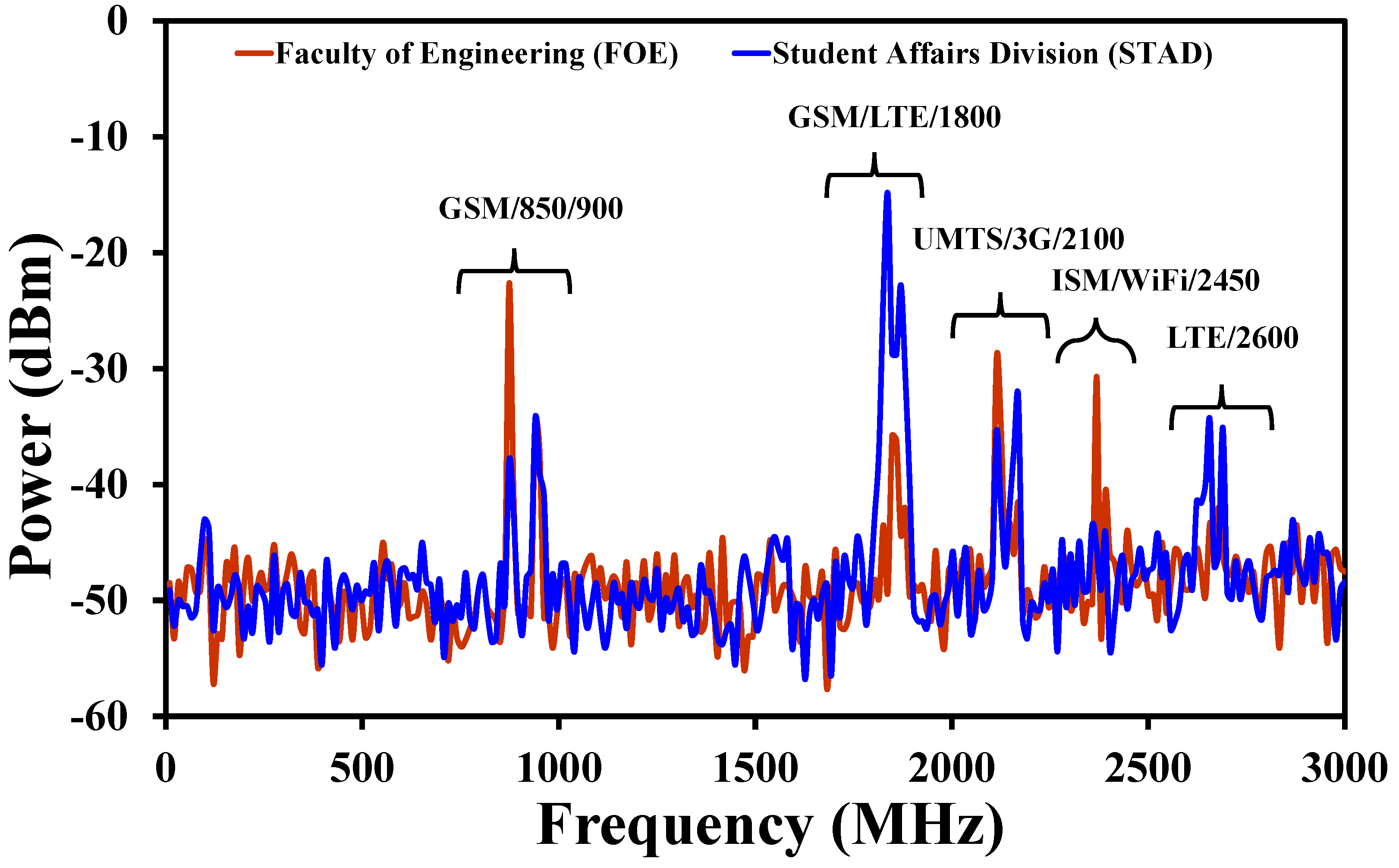
3. RF Spectral Survey
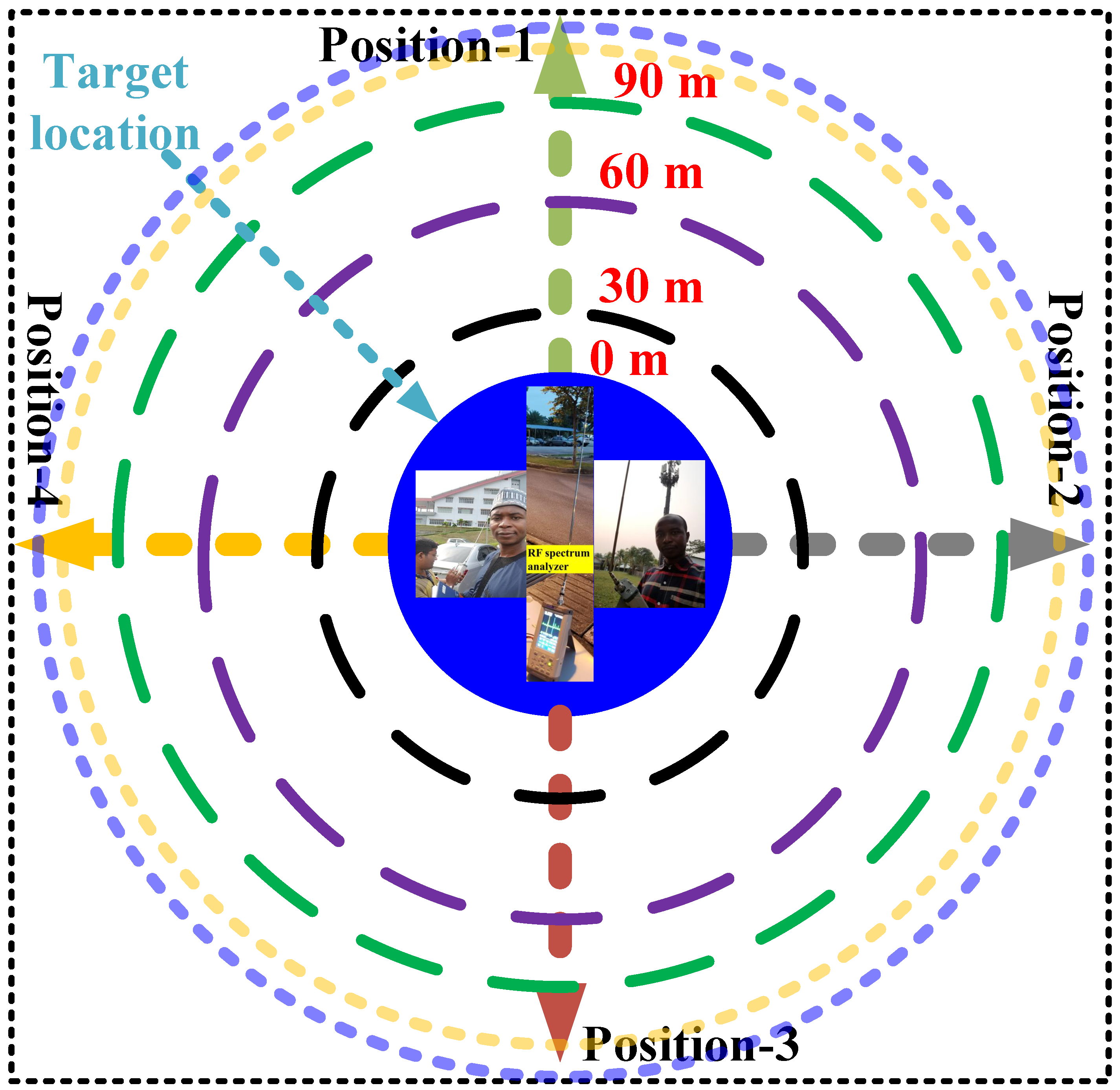
3.1. Site Surveys for Ambient RFEH
3.2. Selection of Available Frequency Bands
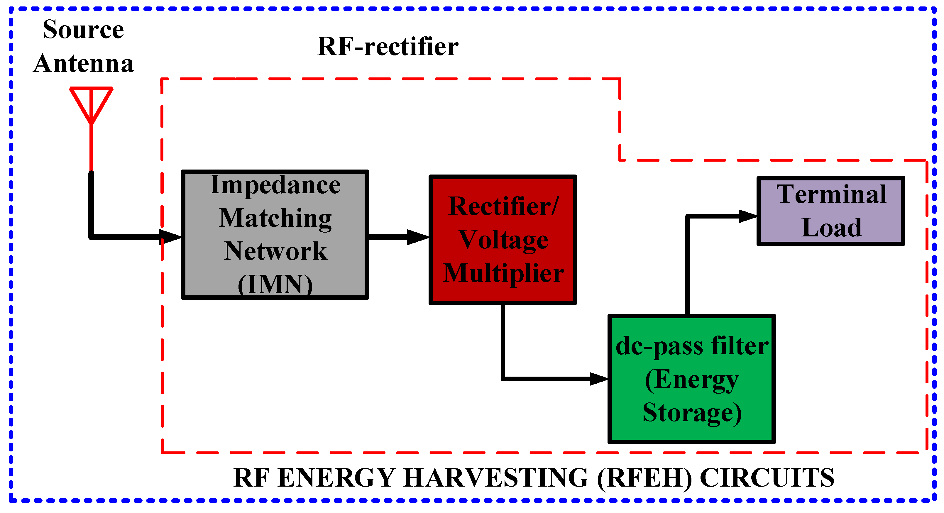
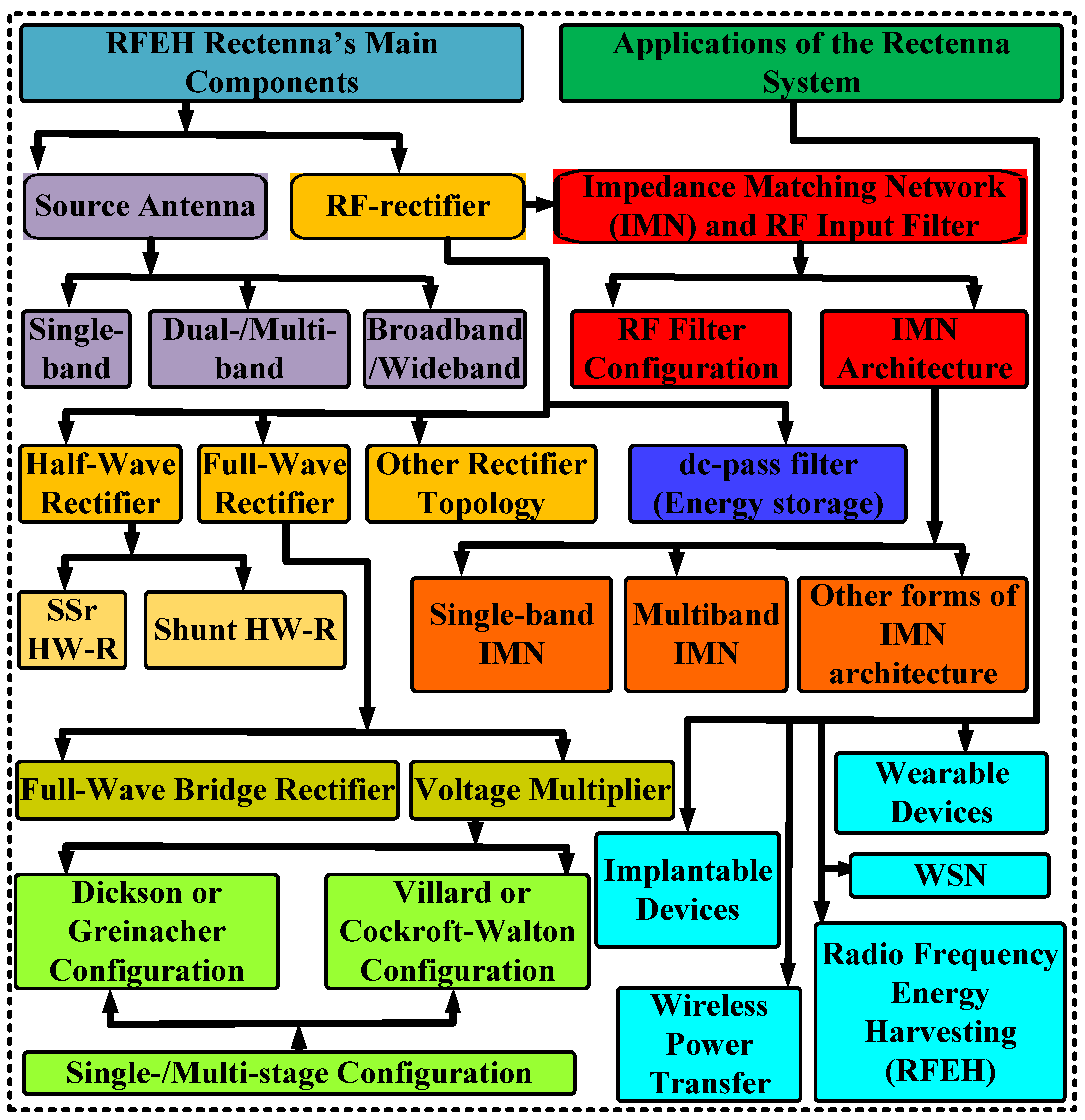
4. RFEH Rectenna
4.1. Antenna for RFEH
- A transmitting antenna: that conveys the outgoing AC signals into communicable EM waves, and
4.1.1. Single-Band Antennae
4.1.2. Dual Band and Multi-Band Antennae
4.1.3. Wideband and Broadband Antennae
4.2. Impedance Matching Network (IMN) for RFEH
4.2.1. Single-Band MN
4.2.2. Multi-Band and Wideband MN
4.3. RF-Rectifier Circuit
4.3.1. Half-Wave Rectifiers
4.3.2. Full-Wave Rectifiers
4.3.3. Other Topologies for Rectifiers and Overview
4.4. DC-Pass Filter
5. Emerging RFEH Studies
- Biomedical implants:
- The employment of flexible substrates, such as paper, polyethylene terephthalate (PET), and textile, can be one of the potential research areas for prospective RFEH harvesters in biomedical implantable devices for BAN applications. The attributes of the material pave the way for the design of a low-profile and conformal rectifier. The level of the DC power realized by a single band or multi-band rectenna can be addressed by cascading multiple RF-rectifier elements through the concept of DC combining;
- 5G technology:
- As 5G and 6G communications evolve, a significant part of potential research in wireless communication systems will either operate or harmonize the spectrum of the mm-wave and sub-millimeter waves. Hence, it is equally important to extend the scope of this research study to accommodate higher frequency bands such as 28, 38, and 60 GHz. Therefore, the proposed RF harvesters demonstrated in this work can be further investigated to address the effects of component loss at the extremely high operating frequency(ies).
- Diode Model:
- The advancement of a low-power rectifying diode is a potential key study area in promoting RFEH technology. Fewer losses, low series resistance (R), enhanced I, high forward bias voltage (V), and a junction impedance or capacitance are some characteristics that need to be further explored;
- Rectenna reconfigurability:
- To improve the level of the ambient RF signals, the concept of dynamic and reconfigurable rectenna arrays can be investigated. An RF and DC combining technique can be deployed, and the array pattern and beam orientation can be modeled as a self-reconfigurable and adaptable module to manage the real-time conditions of the RF signals;
- Miniaturized Optical Rectenna:
- EH from infrared and other forms of visible lights can be investigated in the future using miniaturized optical rectenna. However, the technique suffers from poor PCE due to simple design requirement at optical without provision for MN. The use of a high-impedance reconfigurable antenna is one of the proposed approaches to address this challenge;
- Hybridization:
- The present rectenna module results in a level that makes it difficult for Big Tech companies to commercialize RFEH technology. Hence, the use of hybrid renewable energy harvesting (HREH) technology might revolutionize the process. HREH can be accomplished from diverse renewable energy sources that work in tandem. Therefore, automobiles, military and security surveillance, WSN, biomedical implantable devices, aircraft, wearable devices, and a variety of other platforms can all benefit from HREH technology.
6. Conclusions
Author Contributions
Funding
Acknowledgments
Conflicts of Interest
References
- Caselli, M.; Tonelli, M.; Boni, A. Analysis and design of an integrated RF energy harvester for ultra low-power environments. Int. J. Circuit Theory Appl. 2019, 47, 1086–1104. [Google Scholar] [CrossRef]
- Muncuk, U.; Alemdar, K.; Sarode, J.D.; Chowdhury, K.R. Multiband ambient RF energy harvesting circuit design for enabling batteryless sensors and IoT. IEEE Internet Things J. 2018, 5, 2700–2714. [Google Scholar] [CrossRef]
- Niotaki, K.; Collado, A.; Georgiadis, A.; Kim, S.; Tentzeris, M.M. Solar/electromagnetic energy harvesting and wireless power transmission. Proc. IEEE 2014, 102, 1712–1722. [Google Scholar] [CrossRef]
- Assimonis, S.D.; Daskalakis, S.N.; Bletsas, A. Sensitive and efficient RF harvesting supply for batteryless backscatter sensor networks. IEEE Trans. Microw. Theory Tech. 2016, 64, 1327–1338. [Google Scholar] [CrossRef]
- Kim, S.; Vyas, R.; Bito, J.; Niotaki, K.; Collado, A.; Georgiadis, A.; Tentzeris, M.M. Ambient RF energy-harvesting technologies for self-sustainable standalone wireless sensor platforms. Proc. IEEE 2014, 102, 1649–1666. [Google Scholar] [CrossRef]
- Basir, A.; Yoo, H. Efficient wireless power transfer system with a miniaturized quad-band implantable antenna for deep-body multitasking implants. IEEE Trans. Microw. Theory Tech. 2020, 68, 1943–1953. [Google Scholar] [CrossRef]
- Shafique, K.; Khawaja, B.A.; Khurram, M.D.; Sibtain, S.M.; Siddiqui, Y.; Mustaqim, M.; Chattha, H.T.; Yang, X. Energy harvesting using a low-cost rectenna for Internet of Things (IoT) applications. IEEE Access 2018, 6, 30932–30941. [Google Scholar] [CrossRef]
- La Rosa, R.; Livreri, P.; Trigona, C.; Di Donato, L.; Sorbello, G. Strategies and techniques for powering wireless sensor nodes through energy harvesting and wireless power transfer. Sensors 2019, 19, 2660. [Google Scholar] [CrossRef] [PubMed]
- Nikandish, G.; Staszewski, R.B.; Zhu, A. Breaking the bandwidth limit: A review of broadband Doherty power amplifier design for 5G. IEEE Microw. Mag. 2020, 21, 57–75. [Google Scholar] [CrossRef]
- Wagih, M.; Weddell, A.S.; Beeby, S. Millimeter-wave power harvesting: A review. IEEE Open J. Antennas Propag. 2020, 1, 56–578. [Google Scholar] [CrossRef]
- Riaz, A.; Awais, M.; Farooq, M.M.; Khan, W.T. A single cell dual band rectifier at millimeter-wave frequencies for future 5G communications. In Proceedings of the 2019 49th European Microwave Conference (EuMC), Paris, France, 1–3 October 2019; pp. 41–44. [Google Scholar]
- Jilani, S.F.; Munoz, M.O.; Abbasi, Q.H.; Alomainy, A. Millimeter-wave liquid crystal polymer based conformal antenna array for 5G applications. IEEE Antennas Wirel. Propag. Lett. 2018, 18, 84–88. [Google Scholar] [CrossRef]
- Vuong, T.P.; Bui, D.H.N.; Verdier, J.; Allard, B.; Benech, P. Design and measurement of 3D flexible antenna diversity for ambient RF energy scavenging in indoor scenarios. IEEE Access 2019, 7, 17033–17044. [Google Scholar]
- Andrae, A.S.; Edler, T. On global electricity usage of communication technology: Trends to 2030. Challenges 2015, 6, 117–157. [Google Scholar] [CrossRef]
- Divakaran, S.K.; Krishna, D.D. RF energy harvesting systems: An overview and design issues. Int. J. RF Microw. Comput.-Aided Eng. 2019, 29, e21633. [Google Scholar] [CrossRef]
- Xu, J.; Ricketts, D.S. An efficient, watt-level microwave rectifier using an impedance compression network (ICN) with applications in outphasing energy recovery systems. IEEE Microw. Wirel. Components Lett. 2013, 23, 542–544. [Google Scholar] [CrossRef]
- Leonov, V. Thermoelectric energy harvesting of human body heat for wearable sensors. IEEE Sens. J. 2013, 13, 2284–2291. [Google Scholar] [CrossRef]
- Liu, X.; Ansari, N. Toward green IoT: Energy solutions and key challenges. IEEE Commun. Mag. 2019, 57, 104–110. [Google Scholar] [CrossRef]
- Nguyen, C.V.; Nguyen, M.T.; Quyen, T.V.; Le, A.M.; Masaracchia, A.; Nguyen, H.T.; Nguyen, H.P.; Nguyen, L.D.; Nguyen, H.T.; Nguyen, V.Q. Hybrid solar-RF energy harvesting systems for electric operated wheelchairs. Electronics 2020, 9, 752. [Google Scholar] [CrossRef]
- Roundy, S.; Wright, P.K.; Rabaey, J. A study of low level vibrations as a power source for wireless sensor nodes. Comput. Commun. 2003, 26, 1131–1144. [Google Scholar] [CrossRef]
- Chin, C.H.; Xue, Q.; Chan, C.H. Design of a 5.8-GHz rectenna incorporating a new patch antenna. IEEE Antennas Wirel. Propag. Lett. 2005, 4, 175–178. [Google Scholar] [CrossRef]
- Khan, D.; Oh, S.J.; Yeo, S.; Ryu, Y.; In, S.; Rad, R.E.; Ali, I.; Pu, Y.G.; Yoo, S.S.; Lee, M.; et al. A Solar/Triboelectric/RF Hybrid Energy Harvesting based High Efficiency Wireless Power Receiver. IEEE Trans. Power Electron. 2021, 36, 11148–11162. [Google Scholar] [CrossRef]
- Tesla, N. Experiments with alternate currents of very high frequency and their application to methods of artificial illumination. Trans. Am. Inst. Electr. Eng. 1891, 8, 266–319. [Google Scholar] [CrossRef]
- Khan, D.; Oh, S.J.; Shehzad, K.; Basim, M.; Verma, D.; Pu, Y.G.; Lee, M.; Hwang, K.C.; Yang, Y.; Lee, K.Y. An efficient reconfigurable RF-DC converter with wide input power range for RF energy harvesting. IEEE Access 2020, 8, 79310–79318. [Google Scholar] [CrossRef]
- Yildiz, F. Potential Ambient Energy-Harvesting Sources and Techniques. J. Technol. Stud. 2009, 35, 40–48. [Google Scholar] [CrossRef]
- Bashir, S.; Batool, S.; Imran, M.; Ahmad, M.I.; Malik, F.M.; Ali, U. Development of Frequency Weighted Model Reduction Algorithm with Error Bound: Application to Doubly Fed Induction Generator Based Wind Turbines for Power System. Electronics 2021, 10, 44. [Google Scholar] [CrossRef]
- Parivar, H.; Shivaie, M.; Darahi, A.; Ansari, M. An Efficient Direct Torque Control Strategy for a Doubly Fed Induction Generator (DFIG) in Wind Energy Conversation Systems. In Proceedings of the 2021 IEEE Texas Power and Energy Conference (TPEC), College Station, TX, USA, 2–5 February 2021; pp. 1–5. [Google Scholar]
- Visser, H.J.; Vullers, R.J. RF energy harvesting and transport for wireless sensor network applications: Principles and requirements. Proc. IEEE 2013, 101, 1410–1423. [Google Scholar] [CrossRef]
- Lin, Y.L.; Zhang, X.Y.; Du, Z.X.; Lin, Q.W. High-efficiency microwave rectifier with extended operating bandwidth. IEEE Trans. Circuits Syst. II Express Briefs 2017, 65, 819–823. [Google Scholar] [CrossRef]
- Singh, J.; Kaur, R.; Singh, D. Energy harvesting in wireless sensor networks: A taxonomic survey. Int. J. Energy Res. 2021, 45, 118–140. [Google Scholar] [CrossRef]
- Cansiz, M.; Altinel, D.; Kurt, G.K. Efficiency in RF energy harvesting systems: A comprehensive review. Energy 2019, 174, 292–309. [Google Scholar] [CrossRef]
- Selim, K.K.; Wu, S.; Saleeb, D.A. RF energy scavenging with a wide-range input power level. IEEE Access 2019, 7, 173450–173462. [Google Scholar] [CrossRef]
- Mansour, M.M.; Kanaya, H. Compact and broadband RF rectifier with 1.5 octave bandwidth based on a simple pair of L-section matching network. IEEE Microw. Wirel. Components Lett. 2018, 28, 335–337. [Google Scholar] [CrossRef]
- Muhammad, S.; Tiang, J.J.; Wong, S.K. Design of a Dual-Port Multi-Band Rectifier Circuit. In Proceedings of the 8th Global Conference on Engineering and Technology (CIETR-2020), Global Academy of Training and Research (GATR) Enterprise [002360364-P], Bangkok, Thailand, 12 December 2020; pp. 1–8. [Google Scholar]
- Ellis, M.S.; Zhao, Z.; Wu, J.; Ding, X.; Nie, Z.; Liu, Q.H. A novel simple and compact microstrip-fed circularly polarized wide slot antenna with wide axial ratio bandwidth for C-band applications. IEEE Trans. Antennas Propag. 2016, 64, 1552–1555. [Google Scholar] [CrossRef]
- Valenta, C.R.; Durgin, G.D. Harvesting wireless power: Survey of energy-harvester conversion efficiency in far-field, wireless power transfer systems. IEEE Microw. Mag. 2014, 15, 108–120. [Google Scholar]
- Tesla, N. Apparatus for Transmitting Electrical Energy. U.S. Patent 1,119,732, 1 December 1914. [Google Scholar]
- Midya, M.; Bhattacharjee, S.; Mitra, M. Triple-band dual-sense circularly polarised planar monopole antenna. IET Microwaves Antennas Propag. 2019, 13, 2020–2025. [Google Scholar] [CrossRef]
- Ding, K.; Gao, C.; Yu, T.; Qu, D. Broadband C-shaped circularly polarized monopole antenna. IEEE Trans. Antennas Propag. 2014, 63, 785–790. [Google Scholar] [CrossRef]
- Trainotti, V. Short medium frequency AM antennas. IEEE Trans. Broadcast. 2001, 47, 263–284. [Google Scholar] [CrossRef]
- Sun, H.; Guo, Y.x.; He, M.; Zhong, Z. A dual-band rectenna using broadband Yagi antenna array for ambient RF power harvesting. IEEE Antennas Wirel. Propag. Lett. 2013, 12, 918–921. [Google Scholar] [CrossRef]
- Li, L.; Zhou, Z.; Hong, J.; Wang, B.Z. Compact ultra-wideband printed monopole antenna. Electron. Lett. 2011, 47, 894–896. [Google Scholar] [CrossRef]
- Pinuela, M.; Yates, D.; Mitcheson, P.; Lucyszyn, S. London RF survey for radiative ambient RF energy harvesters and efficient DC-load inductive power transfer. In Proceedings of the 2013 7th European Conference on Antennas and Propagation (EuCAP), Gothenburg, Sweden, 8–12 April 2013; pp. 2839–2843. [Google Scholar]
- Darak, S.J.; Moy, C.; Palicot, J.; Louët, Y. Smart decision making policy for faster harvesting from ambient RF sources in wireless sensor nodes. In Proceedings of the 2016 International Symposium on Wireless Communication Systems (ISWCS), Poznan, Poland, 20–23 September 2016; pp. 148–152. [Google Scholar]
- Bose, I.; Yan, S. The green potential of RFID projects: A case-based analysis. IT Prof. 2011, 13, 41–47. [Google Scholar] [CrossRef]
- Bhatnagar, V.; Owende, P. Energy harvesting for assistive and mobile applications. Energy Sci. Eng. 2015, 3, 153–173. [Google Scholar] [CrossRef]
- Lu, P.; Song, C.; Huang, K.M. Ultra-Wideband Rectenna Using Complementary Resonant Structure for Microwave Power Transmission and Energy Harvesting. IEEE Trans. Microw. Theory Tech. 2021, 69, 3452–3462. [Google Scholar] [CrossRef]
- Kanaujia, B.K.; Singh, N.; Kumar, S. Background and Origin of the Rectenna. In Rectenna: Wireless Energy Harvesting System; Springer: Berlin/Heidelberg, Germany, 2021; pp. 21–48. [Google Scholar]
- Abdelhalem, S.H.; Gudem, P.S.; Larson, L.E. An RF–DC converter with wide-dynamic-range input matching for power recovery applications. IEEE Trans. Circuits Syst. II Express Briefs 2013, 60, 336–340. [Google Scholar] [CrossRef]
- Cai, X.; Wen, G.; Guo, Y. A Compact Rectenna with Flat-Top Angular Coverage for RF Energy Harvesting. IEEE Antennas Wirel. Propag. Lett. 2021, 20, 1307–1311. [Google Scholar] [CrossRef]
- Muhammad, S.; Tiang, J.J.; Wong, S.K. Design of Wideband Circular Slot Antenna for RF Energy Harvesting System. In Proceedings of the DIFCON 2021: Digital Futures International Congress, Online, 21–23 June 2021; p. 74. Available online: https://ieeexplore.ieee.org/abstract/document/6698485 (accessed on 9 February 2022).
- Muhammad, S.; Jiat Tiang, J.; Kin Wong, S.; Iqbal, A.; Alibakhshikenari, M.; Limiti, E. Compact Rectifier Circuit Design for Harvesting GSM/900 Ambient Energy. Electronics 2020, 9, 1614. [Google Scholar] [CrossRef]
- Cheney, M.; Uth, R. Tesla, Master of Lightning; Barnes & Noble Publishing: China, 1999. [Google Scholar]
- Kraus, J.D. Heinrich Hertz-theorist and experimenter. IEEE Trans. Microw. Theory Tech. 1988, 36, 824–829. [Google Scholar] [CrossRef]
- Chandravanshi, S.; Akhtar, M. Design of efficient rectifier using IDC and harmonic rejection filter in GSM/CDMA band for RF energy harvesting. Microw. Opt. Technol. Lett. 2017, 59, 681–686. [Google Scholar] [CrossRef]
- Song, C.; Huang, Y.; Zhou, J.; Zhang, J.; Yuan, S.; Carter, P. A high-efficiency broadband rectenna for ambient wireless energy harvesting. IEEE Trans. Antennas Propag. 2015, 63, 3486–3495. [Google Scholar] [CrossRef]
- Mohan, A.; Mondal, S. An Impedance Matching Strategy for Micro-Scale RF Energy Harvesting Systems. IEEE Trans. Circuits Syst. II Express Briefs 2020, 68, 1458–1462. [Google Scholar] [CrossRef]
- Carlson, W.B. Margaret Cheney, Tesla: Man out of Time (Book Review). Technol. Cult. 1983, 24, 140. [Google Scholar] [CrossRef]
- Muhammad, S.; Tiang, J.J.; Wong, S.K. Design of a broadband Long-Range RF-Rectifier Circuit for Harvesting Ambient Energy. In Proceedings of the DIFCON 2021: Digital Futures International Congress, Online, 21–23 June 2021; p. 82. [Google Scholar]
- Luo, Y.; Chin, K.W. Learning to Charge RF-Energy Harvesting Devices in WiFi Networks. IEEE Syst. J. 2021, 15, 5516–5525. [Google Scholar] [CrossRef]
- Sarker, M.R.; Saad, M.H.M.; Olazagoitia, J.L.; Vinolas, J. Review of Power Converter Impact of Electromagnetic Energy Harvesting Circuits and Devices for Autonomous Sensor Applications. Electronics 2021, 10, 1108. [Google Scholar] [CrossRef]
- Maxwell, J.C. VIII. A dynamical theory of the electromagnetic field. Philos. Trans. R. Soc. Lond. 1865, 459–512. [Google Scholar]
- Tang, X.; Xie, G.; Cui, Y. Self-sustainable Long Range Backscattering Communication Using RF Energy Harvesting. IEEE Internet Things J. 2021, 8, 13737–13749. [Google Scholar] [CrossRef]
- Inbaraj, D.; Kailasam, M.; Sankararajan, R. Statistical analysis on ambient RF energy harvesting for low-power wireless applications. Int. J. Commun. Syst. 2018, 31, e3538. [Google Scholar] [CrossRef]
- Le, G.; Nguyen, N.; Au, N.D.; Seo, C. A Broadband High-Efficiency Rectifier for Mid-field Wireless Power Transfer. IEEE Microw. Wirel. Components Lett. 2021, 31, 913–916. [Google Scholar] [CrossRef]
- Visser, H.J.; Reniers, A.C.; Theeuwes, J.A. Ambient RF energy scavenging: GSM and WLAN power density measurements. In Proceedings of the 2008 38th European Microwave Conference, Amsterdam, The Netherlands, 27–31 October 2008; pp. 721–724. [Google Scholar]
- Le, M.T.; Vu, H.S.; Truong, T.; Vu, H.T.; Nguyen, Q.C. Circularly polarized meandered-loop antenna for ambient RF energy harvesting system. In Proceedings of the 2020 IEEE Eighth International Conference on Communications and Electronics (ICCE), Phu Quoc Island, Vietnam, 13–15 January 2021; pp. 225–229. [Google Scholar]
- Yang, X.X.; Jiang, C.; Elsherbeni, A.Z.; Yang, F.; Wang, Y.Q. A novel compact printed rectenna for data communication systems. IEEE Trans. Antennas Propag. 2013, 61, 2532–2539. [Google Scholar] [CrossRef]
- Bayat, P.; Baghramian, A. A novel self-tuning type-2 fuzzy maximum power point tracking technique for efficiency enhancement of fuel cell based battery chargers. Int. J. Hydrogen Energy 2020, 45, 23275–23293. [Google Scholar] [CrossRef]
- Lin, C.H.; Zhuang, Y.D.; Tsai, D.G.; Wei, H.J.; Liu, T.Y. Performance Enhancement of Vanadium Redox Flow Battery by Treated Carbon Felt Electrodes of Polyacrylonitrile using Atmospheric Pressure Plasma. Polymers 2020, 12, 1372. [Google Scholar] [CrossRef] [PubMed]
- Wang, G.; Gao, Q.; Yan, Y.; Zhang, Y. Transient process optimization of battery cooling on heat transfer enhancement structure. Appl. Therm. Eng. 2021, 182, 115897. [Google Scholar] [CrossRef]
- Huang, Y.; Shinohara, N.; Toromura, H. A wideband rectenna for 2.4 GHz-band RF energy harvesting. In Proceedings of the 2016 IEEE Wireless Power Transfer Conference (WPTC), Aveiro, Portugal, 5–6 May 2016; pp. 1–3. [Google Scholar]
- Ouyang, P.; Jin, C.; Xu, G.; Yang, X.; Kong, K.; Liu, B.; Dan, J.; Chen, J.; Yue, Z.; Li, X.; et al. Lithium ion batteries with enhanced electrochemical performance by using carbon-coated SiOx/Ag composites as anode material. Ceram. Int. 2021, 47, 1086–1094. [Google Scholar] [CrossRef]
- Pardue, C.A.; Bellaredj, M.L.F.; Torun, H.M.; Swaminathan, M.; Kohl, P.; Davis, A.K. RF wireless power transfer using integrated inductor. IEEE Trans. Components Packag. Manuf. Technol. 2018, 9, 913–920. [Google Scholar] [CrossRef]
- Muhammad, S.; Jiat Tiang, J.; Kin Wong, S.; Jamel, N.; Iqbal, A. Design of a Five-Band Dual-Port Rectenna for RF Energy Harvesting. Comput. Mater. Contin. 2021, 69, 487–501. [Google Scholar] [CrossRef]
- Muhammad, S.; Tiang, J.J.; Wong, S.K.; Smida, A.; Ghayoula, R.; Iqbal, A. A Dual-band Ambient Energy Harvesting Rectenna Design for Wireless Power Communications. IEEE Access 2021, 9, 99944–99953. [Google Scholar] [CrossRef]
- Harouni, Z.; Osman, L.; Gharsallah, A. Efficient 2.45 GHz CPW patch antenna including harmonic rejecting device for wireless power transmission. In Proceedings of the Eighth International Multi-Conference on Systems, Signals & Devices, Sousse, Tunisia, 22–25 March 2011; pp. 1–3. [Google Scholar]
- Song, C.; Huang, Y.; Zhou, J.; Carter, P. Improved ultrawideband rectennas using hybrid resistance compression technique. IEEE Trans. Antennas Propag. 2017, 65, 2057–2062. [Google Scholar] [CrossRef]
- Brown, W.; Mims, J.; Heenan, N. An experimental microwave-powered helicopter. In Proceedings of the 1958 IRE International Convention Record, New York, NY, USA, 21–25 March 1966; Volume 13, pp. 225–235. [Google Scholar]
- Glaser, P.E. Power from the sun: Its future. Science 1968, 162, 857–861. [Google Scholar] [CrossRef] [PubMed]
- Hossain, M.M.; Prybutok, V.R. Consumer acceptance of RFID technology: An exploratory study. IEEE Trans. Eng. Manag. 2008, 55, 316–328. [Google Scholar] [CrossRef]
- Tissier, J.; Latrach, M. A 900/1800 MHz dual-band high-efficiency rectenna. Microw. Opt. Technol. Lett. 2019, 61, 1278–1283. [Google Scholar] [CrossRef]
- Moradi, E.; Sydänheimo, L.; Bova, G.S.; Ukkonen, L. Measurement of wireless power transfer to deep-tissue RFID-based implants using wireless repeater node. IEEE Antennas Wirel. Propag. Lett. 2017, 16, 2171–2174. [Google Scholar] [CrossRef]
- Pandey, R.; Shankhwar, A.K.; Singh, A. An improved conversion efficiency of 1.975 to 4.744 GHz rectenna for wireless sensor applications. Prog. Electromagn. Res. C 2021, 109, 217–225. [Google Scholar] [CrossRef]
- Abdi, A.; Aliakbarian, H. A miniaturized UHF-band rectenna for power transmission to deep-body implantable devices. IEEE J. Transl. Eng. Health Med. 2019, 7, 1–11. [Google Scholar] [CrossRef] [PubMed]
- Lui, K.; Murphy, O.; Toumazou, C. A wearable wideband circularly polarized textile antenna for effective power transmission on a wirelessly-powered sensor platform. IEEE Trans. Antennas Propag. 2013, 61, 3873–3876. [Google Scholar] [CrossRef]
- Lu, X.; Wang, P.; Niyato, D.; Kim, D.I.; Han, Z. Wireless networks with RF energy harvesting: A contemporary survey. IEEE Commun. Surv. Tutorials 2014, 17, 757–789. [Google Scholar] [CrossRef]
- Ma, Z.; Vandenbosch, G.A. Wideband harmonic rejection filtenna for wireless power transfer. IEEE Trans. Antennas Propag. 2013, 62, 371–377. [Google Scholar] [CrossRef]
- Pardue, C.A.; Bellaredj, M.L.F.; Davis, A.K.; Swaminathan, M.; Kohl, P.; Fujii, T.; Nakazawa, S. Design and characterization of inductors for self-powered IoT edge devices. IEEE Trans. Components Packag. Manuf. Technol. 2018, 8, 1263–1271. [Google Scholar] [CrossRef]
- Chandrasekaran, K.T.; Agarwal, K.; Nasimuddin; Alphones, A.; Mittra, R.; Karim, M.F. Compact Dual-Band Metamaterial-Based High-Efficiency Rectenna: An Application for Ambient Electromagnetic Energy Harvesting. IEEE Antennas Propag. Mag. 2020, 62, 18–29. [Google Scholar] [CrossRef]
- Song, C.; López-Yela, A.; Huang, Y.; Segovia-Vargas, D.; Zhuang, Y.; Wang, Y.; Zhou, J. A novel quartz clock with integrated wireless energy harvesting and sensing functions. IEEE Trans. Ind. Electron. 2018, 66, 4042–4053. [Google Scholar] [CrossRef]
- Wagih, M.; Weddell, A.S.; Beeby, S. Rectennas for radio-frequency energy harvesting and wireless power transfer: A review of antenna design [antenna applications corner]. IEEE Antennas Propag. Mag. 2020, 62, 95–107. [Google Scholar] [CrossRef]
- Sanou, B. ICT Facts and Figures. 2013. Available online: https://eldis.org/document/A65910 (accessed on 8 June 2021).
- Niotaki, K.; Kim, S.; Jeong, S.; Collado, A.; Georgiadis, A.; Tentzeris, M.M. A compact dual-band rectenna using slot-loaded dual band folded dipole antenna. IEEE Antennas Wirel. Propag. Lett. 2013, 12, 1634–1637. [Google Scholar] [CrossRef]
- Liu, J.; Xue, Q.; Wong, H.; Lai, H.W.; Long, Y. Design and analysis of a low-profile and broadband microstrip monopolar patch antenna. IEEE Trans. Antennas Propag. 2012, 61, 11–18. [Google Scholar] [CrossRef]
- Mishra, D.; De, S.; Jana, S.; Basagni, S.; Chowdhury, K.; Heinzelman, W. Smart RF energy harvesting communications: Challenges and opportunities. IEEE Commun. Mag. 2015, 53, 70–78. [Google Scholar] [CrossRef]
- Boaventura, A.; Belo, D.; Fernandes, R.; Collado, A.; Georgiadis, A.; Carvalho, N.B. Boosting the efficiency: Unconventional waveform design for efficient wireless power transfer. IEEE Microw. Mag. 2015, 16, 87–96. [Google Scholar] [CrossRef]
- Collado, A.; Georgiadis, A. Conformal hybrid solar and electromagnetic (EM) energy harvesting rectenna. IEEE Trans. Circuits Syst. I Regul. Pap. 2013, 60, 2225–2234. [Google Scholar] [CrossRef]
- James, M.C. II. A dynamical theory of the electromagnetic field. Proc. R. Soc. Lond. 1864, 531–536. [Google Scholar] [CrossRef]
- Surender, D.; Khan, T.; Talukdar, F.A.; De, A.; Antar, Y.M.; Freundorfer, A.P. Key Components of Rectenna System: A Comprehensive Survey. IETE J. Res. 2020, 1–27. [Google Scholar] [CrossRef]
- Vullers, R.J.; Van Schaijk, R.; Visser, H.J.; Penders, J.; Van Hoof, C. Energy harvesting for autonomous wireless sensor networks. IEEE Solid-State Circuits Mag. 2010, 2, 29–38. [Google Scholar] [CrossRef]
- ABRACON. Whip Antenna Datasheet PDF. 2018. Available online: http://www.farnell.com/datasheets/2647385.pdf (accessed on 5 July 2019).
- Du, Z.X.; Bo, S.F.; Cao, Y.F.; Ou, J.H.; Zhang, X.Y. Broadband Circularly Polarized Rectenna with Wide Dynamic-Power-Range for Efficient Wireless Power Transfer. IEEE Access 2020, 8, 80561–80571. [Google Scholar] [CrossRef]
- Marinčić, A.; Civrić, Z.; Milovanović, B. Nikola Tesla’s contributions to radio developments. Serbian J. Electr. Eng. 2006, 3, 131–148. [Google Scholar] [CrossRef]
- Song, N.S.; Chin, K.L.; Liang, D.B.B.; Anyi, M. Design of broadband dual-frequency microstrip patch antenna with modified sierpinski fractal geometry. In Proceedings of the 2006 10th IEEE Singapore International Conference on Communication Systems, Singapore, 30 October–1 November 2006; pp. 1–5. [Google Scholar]
- Dafallaa, W.A. Wideband Antenna Design for Frequency Band Between 2.4 and 11 GHz. Ph.D. Thesis, Universiti Teknologi Malaysia, Skudai, Malaysia, 2010. [Google Scholar]
- Balanis, C.A. Antenna Theory: Analysis and Design; John Wiley & Sons: Hoboken, NJ, USA, 2015. [Google Scholar]
- Pozar, D.M. Microwave Engineering; Wiley: Hoboken, NJ, USA, 2012. [Google Scholar]
- Adam, I.; M. Yasin, M.N.; Soh, P.J.; Kamardin, K.; Jamlos, M.F.; Lago, H.; Razalli, M.S. A simple wideband electromagnetically fed circular polarized antenna for energy harvesting. Microw. Opt. Technol. Lett. 2017, 59, 2390–2397. [Google Scholar] [CrossRef]
- Awais, Q.; Jin, Y.; Chattha, H.T.; Jamil, M.; Qiang, H.; Khawaja, B.A. A compact rectenna system with high conversion efficiency for wireless energy harvesting. IEEE Access 2018, 6, 35857–35866. [Google Scholar] [CrossRef]
- Dias, L.F.R.; Boaventua, A.; de Carvalho, N.B. RF-DC converter efficiency optimization using source-pull techniques. In Proceedings of the 2014 International Workshop on Integrated Nonlinear Microwave and Millimetre-Wave Circuits (INMMiC), Leuven, Belgium, 2–4 April 2014; pp. 1–3. [Google Scholar]
- Zhang, R.; Ho, C.K. MIMO broadcasting for simultaneous wireless information and power transfer. IEEE Trans. Wirel. Commun. 2013, 12, 1989–2001. [Google Scholar] [CrossRef]
- Mansour, M.M.; Kanaya, H. Novel L-slot matching circuit integrated with circularly polarized rectenna for wireless energy harvesting. Electronics 2019, 8, 651. [Google Scholar] [CrossRef]
- Muhammad, S.; Ya’u, I.; Abubakar, A.; Yaro, A.S. Design of single feed dual-band millimeter wave antenna for future 5G wireless applications. Sci. World J. 2019, 14, 84–87. [Google Scholar]
- Fujimoto, T.; Jono, K. Wideband rectangular printed monopole antenna for circular polarisation. IET Microwaves Antennas Propag. 2014, 8, 649–656. [Google Scholar] [CrossRef]
- Pakkathillam, J.K.; Kanagasabai, M. Circularly polarized broadband antenna deploying fractal slot geometry. IEEE Antennas Wirel. Propag. Lett. 2015, 14, 1286–1289. [Google Scholar] [CrossRef]
- Soltani, S.; Azarmanesh, M.; Lotfi, P.; Dadashzadeh, G. Two novel very small monopole antennas having frequency band notch function using DGS for UWB application. AEU-Int. J. Electron. Commun. 2011, 65, 87–94. [Google Scholar] [CrossRef]
- Chang, K.M.; Lin, R.J.; Deng, I.C.; Chen, J.B.; Xiang, K.Q.; Rong, C.J. A novel design of a CPW-fed square slot antenna with broadband circular polarization. Microw. Opt. Technol. Lett. 2006, 48, 2456–2459. [Google Scholar] [CrossRef]
- Sabran, M.L.; Rahim, S.K.A.; Soh, P.J.; Leow, C.Y.; Vandenbosch, G. A simple electromagnetically fed circularly-polarized circular microstrip antenna. Appl. Comput. Electromagn. Soc. J. 2015, 30, 1180–1187. [Google Scholar]
- Lee, H.; Lee, S.R.; Lee, K.J.; Kong, H.B.; Lee, I. Transmit beamforming techniques for wireless information and power transfer in MISO interference channels. In Proceedings of the 2015 IEEE Global Communications Conference (GLOBECOM), San Diego, CA, USA, 6–10 December 2015; pp. 1–6. [Google Scholar]
- Chen, Y.S.; You, J.W. A scalable and multidirectional rectenna system for RF energy harvesting. IEEE Trans. Components Packag. Manuf. Technol. 2018, 8, 2060–2072. [Google Scholar] [CrossRef]
- Panahi, A.; Bao, X.; Ruvio, G.; Ammann, M. A printed triangular monopole with wideband circular polarization. IEEE Trans. Antennas Propag. 2014, 63, 415–418. [Google Scholar] [CrossRef]
- Ahmed, S.; Zakaria, Z.; Husain, M.; Ibrahim, I.; Alhegazi, A. Efficient feeding geometries for rectenna design at 2.45 GHz. Electron. Lett. 2017, 53, 1585–1587. [Google Scholar] [CrossRef]
- Zainol, N.; Zakaria, Z.; Abu, M.; Mohamed Yunus, M. A 2.45 GHz harmonic suppression rectangular patch antenna with circular polarization for wireless power transfer application. IETE J. Res. 2018, 64, 310–316. [Google Scholar] [CrossRef]
- Liu, Y.; Huang, K.; Yang, Y.; Zhang, B. A low-profile lightweight circularly polarized rectenna array based on coplanar waveguide. IEEE Antennas Wirel. Propag. Lett. 2018, 17, 1659–1663. [Google Scholar] [CrossRef]
- Masius, A.A.; Wong, Y.C.; Lau, K.T. Miniature high gain slot-fed rectangular dielectric resonator antenna for IoT RF energy harvesting. AEU-Int. J. Electron. Commun. 2018, 85, 39–46. [Google Scholar] [CrossRef]
- Sun, W.J.; Yang, W.W.; Chu, P.; Chen, J.X. A wideband stacked dielectric resonator antenna for 5G applications. Int. J. RF Microw. Comput.-Aided Eng. 2019, 29, e21897. [Google Scholar] [CrossRef]
- Sun, H. An enhanced rectenna using differentially-fed rectifier for wireless power transmission. IEEE Antennas Wirel. Propag. Lett. 2015, 15, 32–35. [Google Scholar] [CrossRef]
- McSpadden, J.O.; Fan, L.; Chang, K. Design and experiments of a high-conversion-efficiency 5.8-GHz rectenna. IEEE Trans. Microw. Theory Tech. 1998, 46, 2053–2060. [Google Scholar] [CrossRef]
- Yu, C.; Tan, F.; Liu, C. A C-band microwave rectenna using aperture-coupled antenna array and novel Class-F rectifier with cavity. J. Electromagn. Waves Appl. 2015, 29, 977–991. [Google Scholar] [CrossRef]
- Singh, M.; Agrawal, S.; Parihar, M.S. Design of a rectenna system for GSM-900 band using novel broadside 2×1 array antenna. J. Eng. 2017, 2017, 232–236. [Google Scholar] [CrossRef]
- Shen, S.; Zhang, Y.; Chiu, C.Y.; Murch, R. Directional Multiport Ambient RF Energy Harvesting System for the Internet of Things. IEEE Internet Things J. 2020, 8, 5850–5865. [Google Scholar] [CrossRef]
- Ladan, S.; Ghassemi, N.; Ghiotto, A.; Wu, K. Highly efficient compact rectenna for wireless energy harvesting application. IEEE Microw. Mag. 2013, 14, 117–122. [Google Scholar] [CrossRef]
- Wang, M.; Yang, L.; Fan, Y.; Shen, M.; Li, Y.; Shi, Y. A compact omnidirectional dual-circinal rectenna for 2.45 GHz wireless power transfer. Int. J. RF Microw. Comput.-Aided Eng. 2019, 29, e21625. [Google Scholar] [CrossRef]
- Huang, F.J.; Lee, C.M.; Chang, C.L.; Chen, L.K.; Yo, T.C.; Luo, C.H. Rectenna application of miniaturized implantable antenna design for triple-band biotelemetry communication. IEEE Trans. Antennas Propag. 2011, 59, 2646–2653. [Google Scholar] [CrossRef]
- Kuhn, V.; Lahuec, C.; Seguin, F.; Person, C. A multi-band stacked RF energy harvester with RF-to-DC efficiency up to 84%. IEEE Trans. Microw. Theory Tech. 2015, 63, 1768–1778. [Google Scholar] [CrossRef]
- Agrawal, S.; Parihar, M.S.; Kondekar, P.N. A dual-band rectenna using broadband DRA loaded with slot. Int. J. Microw. Wirel. Technol. 2018, 10, 59. [Google Scholar] [CrossRef]
- Zeng, M.; Li, Z.; Andrenko, A.S.; Zeng, Y.; Tan, H.Z. A compact dual-band rectenna for GSM900 and GSM1800 energy harvesting. Int. J. Antennas Propag. 2018, 2018, 4781465. [Google Scholar] [CrossRef]
- Shen, S.; Chiu, C.Y.; Murch, R.D. A dual-port triple-band L-probe microstrip patch rectenna for ambient RF energy harvesting. IEEE Antennas Wirel. Propag. Lett. 2017, 16, 3071–3074. [Google Scholar] [CrossRef]
- Liu, J.; Zhang, X.Y.; Yang, C.L. Analysis and design of dual-band rectifier using novel matching network. IEEE Trans. Circuits Syst. II Express Briefs 2017, 65, 431–435. [Google Scholar] [CrossRef]
- Zhu, L.; Zhang, J.; Han, W.; Xu, L.; Bai, X. A novel RF energy harvesting cube based on air dielectric antenna arrays. Int. J. RF Microw. Comput.-Aided Eng. 2019, 29, e21636. [Google Scholar] [CrossRef]
- Sun, H.; Guo, Y.x.; He, M.; Zhong, Z. Design of a high-efficiency 2.45-GHz rectenna for low-input-power energy harvesting. IEEE Antennas Wirel. Propag. Lett. 2012, 11, 929–932. [Google Scholar]
- Hassan, N.; Zakaria, Z.; Sam, W.Y.; Hanapiah, I.N.M.; Mohamad, A.N.; Roslan, A.F.; Ahmad, B.H.; Ismail, M.K.; Abd Aziz, M.Z.A. Design of dual-band microstrip patch antenna with right-angle triangular aperture slot for energy transfer application. Int. J. RF Microw. Comput.-Aided Eng. 2019, 29, e21666. [Google Scholar] [CrossRef]
- Chandravanshi, S.; Sarma, S.S.; Akhtar, M.J. Design of triple band differential rectenna for RF energy harvesting. IEEE Trans. Antennas Propag. 2018, 66, 2716–2726. [Google Scholar] [CrossRef]
- Yusop, M.; Rahim, M.; Ismail, M.; Wahid, A. Circular polarization fractal koch microstrip patch antenna using single-fed EM coupled ring resonators. In Proceedings of the 2010 IEEE Asia-Pacific Conference on Applied Electromagnetics (APACE), Port Dickson, Malaysia, 9–11 November 2010; pp. 1–4. [Google Scholar]
- Mohd Noor, F.S.; Zakaria, Z.; Lago, H.; Meor Said, M.A. Dual-band aperture-coupled rectenna for radio frequency energy harvesting. Int. J. RF Microw. Comput.-Aided Eng. 2019, 29, e21651. [Google Scholar] [CrossRef]
- Lu, J.H.; Wang, S.F. Planar broadband circularly polarized antenna with square slot for UHF RFID reader. IEEE Trans. Antennas Propag. 2012, 61, 45–53. [Google Scholar] [CrossRef]
- Nie, M.J.; Yang, X.X.; Tan, G.N.; Han, B. A compact 2.45-GHz broadband rectenna using grounded coplanar waveguide. IEEE Antennas Wirel. Propag. Lett. 2015, 14, 986–989. [Google Scholar] [CrossRef]
- Agrawal, S.; Gupta, R.D.; Parihar, M.S.; Kondekar, P.N. A wideband high gain dielectric resonator antenna for RF energy harvesting application. AEU-Int. J. Electron. Commun. 2017, 78, 24–31. [Google Scholar] [CrossRef]
- Agrawal, S.; Parihar, M.S.; Kondekar, P. Broadband rectenna for radio frequency energy harvesting application. IETE J. Res. 2018, 64, 347–353. [Google Scholar] [CrossRef]
- Timotheou, S.; Zheng, G.; Masouros, C.; Krikidis, I. Exploiting constructive interference for simultaneous wireless information and power transfer in multiuser downlink systems. IEEE J. Sel. Areas Commun. 2016, 34, 1772–1784. [Google Scholar] [CrossRef]
- Muhammad, S.; Tiang, J.J.; Wong, S.K.; Smida, A.; Waly, M.I.; Iqbal, A. Efficient Quad-band RF Energy Harvesting Rectifier for Wireless Power Communications. AEU-Int. J. Electron. Commun. 2021, 139, 153927. [Google Scholar] [CrossRef]
- Falkenstein, E.; Roberg, M.; Popovic, Z. Low-power wireless power delivery. IEEE Trans. Microw. Theory Tech. 2012, 60, 2277–2286. [Google Scholar] [CrossRef]
- Verma, M.K.; Kanaujia, B.K.; Saini, J.P.; Singh, P. A compact multi-slots loaded gap coupled CP antenna with DGS for WLAN/WiMAX applications. Int. J. RF Microw. Comput.-Aided Eng. 2020, 30, e22431. [Google Scholar] [CrossRef]
- Rezaeieh, S.A.; Abbosh, A.; Antoniades, M.A. Compact CPW-fed planar monopole antenna with wide circular polarization bandwidth. IEEE Antennas Wirel. Propag. Lett. 2013, 12, 1295–1298. [Google Scholar] [CrossRef]
- Jan, J.Y.; Pan, C.Y.; Chiu, K.Y.; Chen, H.M. Broadband CPW-fed circularly-polarized slot antenna with an open slot. IEEE Trans. Antennas Propag. 2012, 61, 1418–1422. [Google Scholar] [CrossRef]
- Bai, X.; Zhang, J.w.; Xu, L.j. A broadband CPW fractal antenna for RF energy harvesting. In Proceedings of the 2017 International Applied Computational Electromagnetics Society Symposium (ACES), Suzhou, China, 1–4 August 2017; pp. 1–2. [Google Scholar]
- Saranya, N.; Kesavamurthy, T. Design and performance analysis of broadband rectenna for an efficient RF energy harvesting application. Int. J. RF Microw. Comput.-Aided Eng. 2019, 29, e21628. [Google Scholar] [CrossRef]
- Kumar, H.; Arrawatia, M.; Kumar, G. Broadband planar log-periodic dipole array antenna based RF-energy harvesting system. IETE J. Res. 2019, 65, 39–43. [Google Scholar] [CrossRef]
- Shi, Y.; Fan, Y.; Li, Y.; Yang, L.; Wang, M. An efficient broadband slotted rectenna for wireless power transfer at LTE band. IEEE Trans. Antennas Propag. 2018, 67, 814–822. [Google Scholar] [CrossRef]
- Lin, Z.; Lin, M.; Zhu, W.P.; Wang, J.B.; Cheng, J. Robust secure beamforming for wireless powered cognitive satellite-terrestrial networks. IEEE Trans. Cogn. Commun. Netw. 2020, 7, 567–580. [Google Scholar] [CrossRef]
- Al-Zoubi, A.; Yang, F.; Kishk, A. A broadband center-fed circular patch-ring antenna with a monopole like radiation pattern. IEEE Trans. Antennas Propag. 2009, 57, 789–792. [Google Scholar] [CrossRef]
- Mavrakis, D. Small Cell Market Status December 2012. 2012. Available online: https://the-mobile-network.com/2021/04/small-cells-market-update-2021/ (accessed on 7 September 2021).
- Palazzi, V.; Del Prete, M.; Fantuzzi, M. Scavenging for energy: A rectenna design for wireless energy harvesting in UHF mobile telephony bands. IEEE Microw. Mag. 2016, 18, 91–99. [Google Scholar] [CrossRef]
- Ntougias, K.; Krikidis, I.; Papageorgiou, G.K.; Sellathurai, M. Hybrid Precoding for MISO Broadcasting SWIPT Systems: A Stochastic Optimization Approach. In Proceedings of the 2020 IEEE 31st Annual International Symposium on Personal, Indoor and Mobile Radio Communications, London, UK, 31 August–3 September 2020; pp. 1–7. [Google Scholar]
- Yang, H.; Xia, X.; Li, J.; Zhu, P.; You, X. Joint Transceiver Design for Network-Assisted Full-Duplex Systems with SWIPT. IEEE Syst. J. 2021, 1–11. [Google Scholar] [CrossRef]
- Muhammad, S.; Yaro, A.S.; Alhassan, I.B. Wide-band 4G Mobile Device Planar Antenna Using Couple Feeding Technique. ATBU J. Sci. Technol. Educ. 2018, 5, 107–116. [Google Scholar]
- Zhang, L.; Jiao, Y.C.; Ding, Y.; Chen, B.; Weng, Z.B. CPW-fed broadband circularly polarized planar monopole antenna with improved ground-plane structure. IEEE Trans. Antennas Propag. 2013, 61, 4824–4828. [Google Scholar] [CrossRef]
- Palazzi, V.; Hester, J.; Bito, J.; Alimenti, F.; Kalialakis, C.; Collado, A.; Mezzanotte, P.; Georgiadis, A.; Roselli, L.; Tentzeris, M.M. A novel ultra-lightweight multiband rectenna on paper for RF energy harvesting in the next generation LTE bands. IEEE Trans. Microw. Theory Tech. 2017, 66, 366–379. [Google Scholar] [CrossRef]
- Cui, L.; Wu, W.; Fang, D.G. Wideband circular patch antenna with conical radiation pattern. IEEE Antennas Wirel. Propag. Lett. 2014, 14, 458–461. [Google Scholar] [CrossRef]
- Marian, V.; Vollaire, C.; Verdier, J.; Allard, B. Potentials of an adaptive rectenna circuit. IEEE Antennas Wirel. Propag. Lett. 2011, 10, 1393–1396. [Google Scholar] [CrossRef]
- Lopez, A.R. Review of narrowband impedance-matching limitations. IEEE Antennas Propag. Mag. 2004, 46, 88–90. [Google Scholar] [CrossRef]
- Alfred, L.R. More on narrowband impedance-matching limitations. IEEE Antennas Propag. Mag. 2004, 46, 102. [Google Scholar]
- Frenzel, L. Back to basics: Impedance matching (part 1). Electron. Des. 2011, 24. Available online: https://www.electronicdesign.com/technologies/communications/article/21796367/back-to-basics-impedance-matching-part-1 (accessed on 15 July 2020).
- Shinohara, N.; Matsumoto, H. Experimental study of large rectenna array for microwave energy transmission. IEEE Trans. Microw. Theory Tech. 1998, 46, 261–268. [Google Scholar] [CrossRef]
- Yang, S.; Lee, K.F.; Kishk, A.; Luk, K.M. Design and study of wideband single feed circularly polarized microstrip antennas. Prog. Electromagn. Res. 2008, 80, 45–61. [Google Scholar] [CrossRef]
- Choi, J.; Chung, K.; Roh, Y. Parametric analysis of a band-rejection antenna for UWB application. Microw. Opt. Technol. Lett. 2005, 47, 287–290. [Google Scholar] [CrossRef]
- Liang, W.L.; Jiao, Y.C.; Zhang, L.; Ni, T. Wideband single-feed circularly polarized antenna. Prog. Electromagn. Res. Lett. 2015, 54, 93–99. [Google Scholar] [CrossRef]
- Bolos, F.; Belo, D.; Georgiadis, A. A UHF rectifier with one octave bandwidth based on a non-uniform transmission line. In Proceedings of the 2016 IEEE MTT-S International Microwave Symposium (IMS), San Francisco, CA, USA, 22–27 May 2016; pp. 1–3. [Google Scholar]
- Soyata, T.; Copeland, L.; Heinzelman, W. RF energy harvesting for embedded systems: A survey of tradeoffs and methodology. IEEE Circuits Syst. Mag. 2016, 16, 22–57. [Google Scholar] [CrossRef]
- Du, Z.X.; Zhang, X.Y. High-efficiency single-and dual-band rectifiers using a complex impedance compression network for wireless power transfer. IEEE Trans. Ind. Electron. 2017, 65, 5012–5022. [Google Scholar] [CrossRef]
- Heydari Nasab, S.; Asefi, M.; Albasha, L.; Qaddoumi, N. Investigation of RF signal energy harvesting. Act. Passiv. Electron. Components 2010, 2010, 591640. [Google Scholar] [CrossRef]
- Shen, S.; Chiu, C.Y.; Murch, R.D. Multiport pixel rectenna for ambient RF energy harvesting. IEEE Trans. Antennas Propag. 2017, 66, 644–656. [Google Scholar] [CrossRef]
- Shanpu, S.; Zhang, Y.; Chiu, C.Y.; Murch, R. An ambient RF energy harvesting system where the number of antenna ports is dependent on frequency. IEEE Trans. Microw. Theory Tech. 2019, 67, 3821–3832. [Google Scholar]
- Mansour, M.M.; Kanaya, H. High-efficient broadband CPW RF rectifier for wireless energy harvesting. IEEE Microw. Wirel. Components Lett. 2019, 29, 288–290. [Google Scholar] [CrossRef]
- Adam, I.; M. Yasin, M.N.; A. Rahim, H.; Soh, P.J.; Abdulmalek, M.F. A compact dual-band rectenna for ambient RF energy harvesting. Microw. Opt. Technol. Lett. 2018, 60, 2740–2748. [Google Scholar] [CrossRef]
- Partal, H.P.; Belen, M.A.; Partal, S.Z. Design and realization of an ultra-low power sensing RF energy harvesting module with its RF and DC sub-components. Int. J. RF Microw. Comput.-Aided Eng. 2019, 29, e21622. [Google Scholar] [CrossRef]
- Hertz, H. Electric Waves’ English Translation by JONES, DE, 1893. Available online: https://www.abebooks.com/Electric-Waves-Authorised-English-Translation-Jones/30774333566/bd (accessed on 10 February 2020).
- Le, T.; Mayaram, K.; Fiez, T. Efficient far-field radio frequency energy harvesting for passively powered sensor networks. IEEE J. Solid-State Circuits 2008, 43, 1287–1302. [Google Scholar] [CrossRef]
- Saffari, P.; Basaligheh, A.; Moez, K. An rf-to-dc rectifier with high efficiency over wide input power range for rf energy harvesting applications. IEEE Trans. Circuits Syst. I Regul. Pap. 2019, 66, 4862–4875. [Google Scholar] [CrossRef]
- Yoo, T.W.; Chang, K. Theoretical and experimental development of 10 and 35 GHz rectennas. IEEE Trans. Microw. Theory Tech. 1992, 40, 1259–1266. [Google Scholar] [CrossRef]
- Behera, B.R.; Meher, P.R.; Mishra, S.K. Microwave antennas–An intrinsic part of RF energy harvesting systems: A contingent study about its design methodologies and state-of-art technologies in current scenario. Int. J. RF Microw. Comput.-Aided Eng. 2020, 30, e22148. [Google Scholar] [CrossRef]
- Md Din, N.; Chakrabarty, C.K.; Bin Ismail, A.; Devi, K.K.A.; Chen, W.Y. Design of RF energy harvesting system for energizing low power devices. Prog. Electromagn. Res. 2012, 132, 49–69. [Google Scholar] [CrossRef]
- Marian, V.; Menudier, C.; Thevenot, M.; Vollaire, C.; Verdier, J.; Allard, B. Efficient design of rectifying antennas for low power detection. In Proceedings of the 2011 IEEE MTT-S International Microwave Symposium, Baltimore, MD, USA, 5–10 June 2011; pp. 1–4. [Google Scholar]
- Skaik, T. A quad-band rectifier design with improved matching bandwidth for RF energy harvesting applications. In Proceedings of the 2017 International Conference on Promising Electronic Technologies (ICPET), Deir El-Balah, Palestine, 16–17 October 2017; pp. 82–86. [Google Scholar]
- Park, J.Y.; Han, S.M.; Itoh. A rectenna design with harmonic-rejecting circular-sector antenna. IEEE Antennas Wirel. Propag. Lett. 2004, 3, 52–54. [Google Scholar] [CrossRef]
- Alex-Amor, A.; Palomares-Caballero, Á.; Fernández-González, J.M.; Padilla, P.; Marcos, D.; Sierra-Castañer, M.; Esteban, J. RF energy harvesting system based on an archimedean spiral antenna for low-power sensor applications. Sensors 2019, 19, 1318. [Google Scholar] [CrossRef] [PubMed]
- Elhebeary, M.R.; Ibrahim, M.A.; Aboudina, M.M.; Mohieldin, A.N. Dual-source self-start high-efficiency microscale smart energy harvesting system for IoT. IEEE Trans. Ind. Electron. 2017, 65, 342–351. [Google Scholar] [CrossRef]
- Eshtiaghi, R.; Zaker, R.; Nouronia, J.; Ghobadi, C. UWB semi-elliptical printed monopole antenna with subband rejection filter. AEU-Int. J. Electron. Commun. 2010, 64, 133–141. [Google Scholar] [CrossRef]
- Ltd, N.D.K.C. Dengyo Rectennas Tokyo, Japan, 2012. Available online: https://techcrunch.com/2011/08/03/harvesting-energy-from-radio-signals-two-new-devices-from-japan-video/ (accessed on 2 May 2018).
- Agrawal, S.; Parihar, M.S.; Kondekar, P.N. Exact Performance Evaluation of RF Energy Harvesting with Different Circuit’s Elements. IETE Tech. Rev. 2018, 35, 514–522. [Google Scholar] [CrossRef]
- Chang, Y.; Zhang, P.; Wang, L. Highly efficient differential rectenna for RF energy harvesting. Microw. Opt. Technol. Lett. 2019, 61, 2662–2668. [Google Scholar] [CrossRef]
- Nimo, A.; Grgic, D.; Reindl, L.M. Impedance optimization of wireless electromagnetic energy harvesters for maximum output efficiency at μW input power. In Proceedings of the Active and Passive Smart Structures and Integrated Systems 2012, San Diego, CA, USA, 12–15 March 2012; Volume 8341, p. 83410W. [Google Scholar] [CrossRef]
- Ungan, T.; Le Polozec, X.; Walker, W.; Reindl, L. RF energy harvesting design using high Q resonators. In Proceedings of the 2009 IEEE MTT-S International Microwave Workshop on Wireless Sensing, Local Positioning, and RFID, Cavtat, Croatia, 24–25 September 2009; pp. 1–4. [Google Scholar]
- Saeed, W.; Shoaib, N.; Cheema, H.M.; Khan, M.U. RF energy harvesting for ubiquitous, zero power wireless sensors. Int. J. Antennas Propag. 2018, 2018, 8903139. [Google Scholar] [CrossRef]
- Muhammad, S.; Jiat Tiang, J.; Kin Wong, S.; Iqbal, A.; Amor, S.; Mohamed Karim, A. A Compact Dual-Port Multi-Band Rectifier Circuit for RF Energy Harvesting. Comput. Mater. Contin. 2021, 68, 167–184. [Google Scholar] [CrossRef]
- Ajmal, T.; Dyo, V.; Allen, B.; Jazani, D.; Ivanov, I. Design and optimisation of compact RF energy harvesting device for smart applications. Electron. Lett. 2014, 50, 111–113. [Google Scholar] [CrossRef]
- Ali, M.; Yang, G.; Dougal, R. Miniature circularly polarized rectenna with reduced out-of-band harmonics. IEEE Antennas Wirel. Propag. Lett. 2006, 5, 107–110. [Google Scholar] [CrossRef]
- Suh, Y.H.; Chang, K. A high-efficiency dual-frequency rectenna for 2.45-and 5.8-GHz wireless power transmission. IEEE Trans. Microw. Theory Tech. 2002, 50, 1784–1789. [Google Scholar] [CrossRef]
- Suh, Y.H.; Wang, C.; Chang, K. Circularly polarised truncated-corner square patch microstrip rectenna for wireless power transmission. Electron. Lett. 2000, 36, 600–602. [Google Scholar] [CrossRef]
- Ren, Y.J.; Chang, K. 5.8-GHz circularly polarized dual-diode rectenna and rectenna array for microwave power transmission. IEEE Trans. Microw. Theory Tech. 2006, 54, 1495–1502. [Google Scholar]
- Niotaki, K.; Georgiadis, A.; Collado, A.; Vardakas, J.S. Dual-band resistance compression networks for improved rectifier performance. IEEE Trans. Microw. Theory Tech. 2014, 62, 3512–3521. [Google Scholar] [CrossRef]
- Bhatt, K.; Kumar, S.; Kumar, P.; Tripathi, C.C. Highly efficient 2.4 and 5.8 GHz dual-band rectenna for energy harvesting applications. IEEE Antennas Wirel. Propag. Lett. 2019, 18, 2637–2641. [Google Scholar] [CrossRef]
- Nagaveni, S.; Kaddi, P.; Khandekar, A.; Dutta, A. Resistance compression dual-band differential CMOS RF energy harvester under modulated signal excitation. IEEE Trans. Circuits Syst. I Regul. Pap. 2020, 67, 4053–4062. [Google Scholar] [CrossRef]
- Colaiuda, D.; Ulisse, I.; Ferri, G. Rectifiers’ Design and Optimization for a Dual-Channel RF Energy Harvester. J. Low Power Electron. Appl. 2020, 10, 11. [Google Scholar] [CrossRef]
- Agrawal, S.; Parihar, M.S.; Kondekar, P. A dual-band RF energy harvesting circuit using 4th order dual-band matching network. Cogent Eng. 2017, 4, 1332705. [Google Scholar] [CrossRef]
- Abdallah, M.; Costantine, J.; Ramadan, A.H.; Tawk, Y. Enhanced radio frequency rectifier with a power splitting/combining topology for wireless energy transfer and harvesting. IET Microwaves Antennas Propag. 2019, 13, 1280–1286. [Google Scholar] [CrossRef]
- Huang, F.J.; Yo, T.C.; Lee, C.M.; Luo, C.H. Design of circular polarization antenna with harmonic suppression for rectenna application. IEEE Antennas Wirel. Propag. Lett. 2012, 11, 592–595. [Google Scholar] [CrossRef]
- Li, P.; Long, Z.; Yang, Z. RF Energy Harvesting for Battery-Less and Maintenance-Free Condition Monitoring of Railway Tracks. IEEE Internet Things J. 2020, 8, 3512–3523. [Google Scholar] [CrossRef]
- Palazzi, V.; Kalialakis, C.; Alimenti, F.; Mezzanotte, P.; Roselli, L.; Collado, A.; Georgiadis, A. Design of a ultra-compact low-power rectenna in paper substrate for energy harvesting in the Wi-Fi band. In Proceedings of the 2016 IEEE Wireless Power Transfer Conference (WPTC), Aveiro, Portugal, 5–6 May 2016; pp. 1–4. [Google Scholar]
- Shariati, N.; Rowe, W.S.; Scott, J.R.; Ghorbani, K. Multi-service highly sensitive rectifier for enhanced RF energy scavenging. Sci. Rep. 2015, 5, 9655. [Google Scholar] [CrossRef] [PubMed]
- Shen, S.; Zhang, Y.; Chiu, C.Y.; Murch, R.D. A Triple-band High-Gain Multibeam Ambient RF Energy Harvesting System Utilizing Hybrid Combining. IEEE Trans. Ind. Electron. 2019, 67, 9215–9226. [Google Scholar] [CrossRef]
- Hsu, C.Y.; Lin, S.C.; Tsai, Z.M. Quadband rectifier using resonant matching networks for enhanced harvesting capability. IEEE Microw. Wirel. Components Lett. 2017, 27, 669–671. [Google Scholar] [CrossRef]
- Liu, J.; Zhang, X.Y. Compact triple-band rectifier for ambient RF energy harvesting application. IEEE Access 2018, 6, 19018–19024. [Google Scholar] [CrossRef]
- Lu, J.J.; Yang, X.X.; Mei, H.; Tan, C. A four-band rectifier with adaptive power for electromagnetic energy harvesting. IEEE Microw. Wirel. Components Lett. 2016, 26, 819–821. [Google Scholar] [CrossRef]
- Zeng, M.; Li, Z.; Andrenko, A.S.; Liu, X.; Tan, H.Z. Differential voltage octuple rectifiers for wireless energy harvesting. Microw. Opt. Technol. Lett. 2017, 59, 1574–1578. [Google Scholar] [CrossRef]
- Khalid, F.; Saeed, W.; Shoaib, N.; Khan, M.U.; Cheema, H.M. Quad-band 3D rectenna array for ambient RF energy harvesting. Int. J. Antennas Propag. 2020, 2020, 7169846. [Google Scholar] [CrossRef]
- Song, C.; Huang, Y.; Carter, P.; Zhou, J.; Yuan, S.; Xu, Q.; Kod, M. A novel six-band dual CP rectenna using improved impedance matching technique for ambient RF energy harvesting. IEEE Trans. Antennas Propag. 2016, 64, 3160–3171. [Google Scholar] [CrossRef]
- Singh, N.; Kanaujia, B.K.; Beg, M.T.; Mainuddin; Khan, T.; Kumar, S. A dual polarized multiband rectenna for RF energy harvesting. AEU-Int. J. Electron. Commun. 2018, 93, 123–131. [Google Scholar] [CrossRef]
- Tafekirt, H.; Pelegri-Sebastia, J.; Bouajaj, A.; Reda, B.M. A sensitive triple-band rectifier for energy harvesting applications. IEEE Access 2020, 8, 73659–73664. [Google Scholar] [CrossRef]
- Yoo, T.; Chang, K. 35 GHz integrated circuit rectifying antenna with 33% efficiency. Electron. Lett. 1991, 27, 2117. [Google Scholar] [CrossRef]
- Singh, N.; Kanaujia, B.; Beg, M.; Mainuddin.; Kumar, S.; Choi, H.C.; Kim, K.W. Low profile multiband rectenna for efficient energy harvesting at microwave frequencies. Int. J. Electron. 2019, 106, 2057–2071. [Google Scholar] [CrossRef]
- East, T.W. A self-steering array for the SHARP microwave-powered aircraft. IEEE Trans. Antennas Propag. 1992, 40, 1565–1567. [Google Scholar] [CrossRef]
- Lin, Q.W.; Zhang, X.Y. Differential rectifier using resistance compression network for improving efficiency over extended input power range. IEEE Trans. Microw. Theory Tech. 2016, 64, 2943–2954. [Google Scholar] [CrossRef]
- Pham, B.L.; Pham, A.V. Triple bands antenna and high efficiency rectifier design for RF energy harvesting at 900, 1900 and 2400 MHz. In Proceedings of the 2013 IEEE MTT-S International Microwave Symposium Digest (MTT), Seattle, WA, USA, 2–7 June 2013; pp. 1–3. [Google Scholar]
- Piñuela, M.; Mitcheson, P.D.; Lucyszyn, S. Ambient RF energy harvesting in urban and semi-urban environments. IEEE Trans. Microw. Theory Tech. 2013, 61, 2715–2726. [Google Scholar] [CrossRef]
- Olgun, U.; Chen, C.C.; Volakis, J.L. Design of an efficient ambient WiFi energy harvesting system. IET Microwaves Antennas Propag. 2012, 6, 1200–1206. [Google Scholar] [CrossRef]
- Masotti, D.; Costanzo, A.; Del Prete, M.; Rizzoli, V. Genetic-based design of a tetra-band high-efficiency radio-frequency energy harvesting system. IET Microwaves Antennas Propag. 2013, 7, 1254–1263. [Google Scholar] [CrossRef]
- Oka, T.; Ogata, T.; Saito, K.; Tanaka, S. Triple-band single-diode microwave rectifier using CRLH transmission line. In Proceedings of the 2014 Asia-Pacific Microwave Conference, Sendai, Japan, 4–7 November 2014; pp. 1013–1015. [Google Scholar]
- Singh, N.; Kanaujia, B.K.; Tariq Beg, M.; Mainuddin; Kumar, S. A triple band circularly polarized rectenna for RF energy harvesting. Electromagnetics 2019, 39, 481–490. [Google Scholar] [CrossRef]
- Kimionis, J.; Collado, A.; Tentzeris, M.M.; Georgiadis, A. Octave and decade printed UWB rectifiers based on nonuniform transmission lines for energy harvesting. IEEE Trans. Microw. Theory Tech. 2017, 65, 4326–4334. [Google Scholar] [CrossRef]
- Abbasian, S.; Johnson, T. High efficiency GaN HEMT synchronous rectifier with an octave bandwidth for wireless power applications. In Proceedings of the 2016 IEEE MTT-S International Microwave Symposium (IMS), San Francisco, CA, USA, 22–27 May 2016; pp. 1–4. [Google Scholar]
- Guo, J.; Zhang, H.; Zhu, X. Theoretical analysis of RF-DC conversion efficiency for class-F rectifiers. IEEE Trans. Microw. Theory Tech. 2014, 62, 977–985. [Google Scholar] [CrossRef]
- Chandravanshi, S.; Katare, K.K.; Akhtar, M.J. Broadband integrated rectenna using differential rectifier and hybrid coupler. IET Microwaves Antennas Propag. 2020, 14, 1384–1395. [Google Scholar] [CrossRef]
- Bava, G.; Pisani, U.; Pozzolo, V. ’Source-pull’technique at microwave frequencies. Electron. Lett. 1984, 20, 152–154. [Google Scholar] [CrossRef]
- Nimo, A.; Grgić, D.; Reindl, L.M. Optimization of passive low power wireless electromagnetic energy harvesters. Sensors 2012, 12, 13636–13663. [Google Scholar] [CrossRef] [PubMed]
- Luo, Y.; Pu, L.; Wang, G.; Zhao, Y. RF Energy Harvesting Wireless Communications: RF Environment, Device Hardware and Practical Issues. Sensors 2019, 19, 3010. [Google Scholar] [CrossRef]
- Zhang, X.Y.; Du, Z.X.; Xue, Q. High-efficiency broadband rectifier with wide ranges of input power and output load based on branch-line coupler. IEEE Trans. Circuits Syst. I Regul. Pap. 2016, 64, 731–739. [Google Scholar] [CrossRef]
- Hagerty, J.A.; Helmbrecht, F.B.; McCalpin, W.H.; Zane, R.; Popovic, Z.B. Recycling ambient microwave energy with broad-band rectenna arrays. IEEE Trans. Microw. Theory Tech. 2004, 52, 1014–1024. [Google Scholar] [CrossRef]
- Song, C.; Huang, Y.; Zhou, J.; Carter, P.; Yuan, S.; Xu, Q.; Fei, Z. Matching network elimination in broadband rectennas for high-efficiency wireless power transfer and energy harvesting. IEEE Trans. Ind. Electron. 2016, 64, 3950–3961. [Google Scholar] [CrossRef]
- Mansour, M.; Le Polozec, X.; Kanaya, H. Enhanced broadband RF differential rectifier integrated with archimedean spiral antenna for wireless energy harvesting applications. Sensors 2019, 19, 655. [Google Scholar] [CrossRef]
- Mahfoudi, H.; Tellache, M.; Takhedmit, H. A wideband rectifier array on dual-polarized differential-feed fractal slotted ground antenna for RF energy harvesting. Int. J. RF Microw. Comput.-Aided Eng. 2019, 29, e21775. [Google Scholar] [CrossRef]
- Singh, N.; Kumar, S.; Kanaujia, B.K.; Beg, M.T.; Mainuddin; Kumar, S. A compact and efficient graphene FET based RF energy harvester for green communication. AEU-Int. J. Electron. Commun. 2020, 115, 153059. [Google Scholar] [CrossRef]
- Song, C.; Huang, Y.; Carter, P.; Zhou, J.; Joseph, S.D.; Li, G. Novel compact and broadband frequency-selectable rectennas for a wide input-power and load impedance range. IEEE Trans. Antennas Propag. 2018, 66, 3306–3316. [Google Scholar] [CrossRef]
- Daskalakis, S.N.; Georgiadis, A.; Goussetis, G.; Tentzeris, M.M. A rectifier circuit insensitive to the angle of incidence of incoming waves based on a Wilkinson power combiner. IEEE Trans. Microw. Theory Tech. 2019, 67, 3210–3218. [Google Scholar] [CrossRef]
- Wang, Y.Q.; Yang, X.X. Design of a high-efficiency circularly polarized rectenna for 35 GHz microwave power transmission system. In Proceedings of the 2012 Asia-Pacific Power and Energy Engineering Conference, Shanghai, China, 27–29 March 2012; pp. 1–4. [Google Scholar]
- Marian, V.; Allard, B.; Vollaire, C.; Verdier, J. Strategy for microwave energy harvesting from ambient field or a feeding source. IEEE Trans. Power Electron. 2012, 27, 4481–4491. [Google Scholar] [CrossRef]
- Chen, Y.S.; Chiu, C.W. Maximum achievable power conversion efficiency obtained through an optimized rectenna structure for RF energy harvesting. IEEE Trans. Antennas Propag. 2017, 65, 2305–2317. [Google Scholar] [CrossRef]
- Arrawatia, M.; Baghini, M.S.; Kumar, G. Broadband bent triangular omnidirectional antenna for RF energy harvesting. IEEE Antennas Wirel. Propag. Lett. 2015, 15, 36–39. [Google Scholar] [CrossRef]
- Kotani, K.; Sasaki, A.; Ito, T. High-efficiency differential-drive CMOS rectifier for UHF RFIDs. IEEE J. Solid-State Circuits 2009, 44, 3011–3018. [Google Scholar] [CrossRef]
- Kuzle, I.; Pandzic, H.; Bosnjak, D. The true inventor of the radio communications. In Proceedings of the 2008 IEEE History of Telecommunications Conference, Paris, France, 11–12 September 2008; pp. 20–23. [Google Scholar]
- Park, J.; Kim, Y.; Yoon, Y.J.; So, J.; Shin, J. Rectifier design using distributed Greinacher voltage multiplier for high frequency wireless power transmission. J. Electromagn. Eng. Sci. 2014, 14, 25–30. [Google Scholar] [CrossRef]
- Gozel, M.A.; Kahriman, M.; Kasar, O. Design of an efficiency-enhanced Greinacher rectifier operating in the GSM 1800 band by using rat-race coupler for RF energy harvesting applications. Int. J. RF Microw. Comput.-Aided Eng. 2019, 29, e21621. [Google Scholar] [CrossRef]
- Brown, W.C. The history of power transmission by radio waves. IEEE Trans. Microw. Theory Tech. 1984, 32, 1230–1242. [Google Scholar] [CrossRef]
- Fan, S.; Yuan, Z.; Gou, W.; Zhao, Y.; Song, C.; Huang, Y.; Zhou, J.; Geng, L. A 2.45-GHz rectifier-booster regulator with impedance matching converters for wireless energy harvesting. IEEE Trans. Microw. Theory Tech. 2019, 67, 3833–3843. [Google Scholar] [CrossRef]
- Han, Y.; Leitermann, O.; Jackson, D.A.; Rivas, J.M.; Perreault, D.J. Resistance compression networks for radio-frequency power conversion. IEEE Trans. Power Electron. 2007, 22, 41–53. [Google Scholar] [CrossRef]
- Barton, T.W.; Gordonson, J.M.; Perreault, D.J. Transmission line resistance compression networks and applications to wireless power transfer. IEEE J. Emerg. Sel. Top. Power Electron. 2014, 3, 252–260. [Google Scholar] [CrossRef]
- Wang, Z.; Zhang, W.; Jin, D.; Xie, H.; Lv, X. A full-wave RF energy harvester based on new configurable diode connected MOSFETs. In Proceedings of the 2016 IEEE International Conference on Microwave and Millimeter Wave Technology (ICMMT), Beijing, China, 5–8 June 2016; Volume 1, pp. 117–119. [Google Scholar]
- Sun, H.; Zhong, Z.; Guo, Y.X. An adaptive reconfigurable rectifier for wireless power transmission. IEEE Microw. Wirel. Components Lett. 2013, 23, 492–494. [Google Scholar] [CrossRef]
- Li, C.J.; Lee, T.C. 2.4-GHz high-efficiency adaptive power. IEEE Trans. Very Large Scale Integr. (VLSI) Syst. 2013, 22, 434–438. [Google Scholar] [CrossRef]
- Liu, Z.; Zhong, Z.; Guo, Y.X. Enhanced dual-band ambient RF energy harvesting with ultra-wide power range. IEEE Microw. Wirel. Components Lett. 2015, 25, 630–632. [Google Scholar] [CrossRef]
- Boot, H.A.; Randall, J.T. Historical notes on the cavity magnetron. IEEE Trans. Electron Devices 1976, 23, 724–729. [Google Scholar] [CrossRef]
- Broadcom, L. HSMS-2850 Datasheet PDF. 2014. Available online: https://www.farnell.com/datasheets/47810.pdf (accessed on 15 September 2019).
- Masotti, D.; Costanzo, A.; Francia, P.; Filippi, M.; Romani, A. A load-modulated rectifier for RF micropower harvesting with start-up strategies. IEEE Trans. Microw. Theory Tech. 2014, 62, 994–1004. [Google Scholar] [CrossRef]
- Wong, S.W.; Sun, G.H.; Zhu, L.; Chen, Z.N.; Chu, Q.X. Integration of Wireless Coil and Bluetooth Antenna for High Charging and Radiation Efficiencies. IEEE Trans. Components Packag. Manuf. Technol. 2018, 8, 1292–1299. [Google Scholar] [CrossRef]
- Bernard, W.C. Tesla: Inventor of the Electrical Age; Princeton University Press: Princeton, NJ, USA, 2015. [Google Scholar]
- Nimo, A.; Beckedahl, T.; Ostertag, T.; Reindl, L. Analysis of passive RF-DC power rectification and harvesting wireless RF energy for micro-watt sensors. AIMS Energy 2015, 3, 184–200. [Google Scholar] [CrossRef]
- Strassner, B.; Chang, K. Microwave power transmission: Historical milestones and system components. Proc. IEEE 2013, 101, 1379–1396. [Google Scholar] [CrossRef]
- Eltresy, N.; Eisheakh, D.; Abdallah, E.; Elhenawy, H. RF energy harvesting using efficiency dual band rectifier. In Proceedings of the 2018 Asia-Pacific Microwave Conference (APMC), Kyoto, Japan, 6–9 November 2018; pp. 1453–1455. [Google Scholar]
- Mouapi, A.; Hakem, N. A selective rectifier for RF energy harvesting for IoT applications. In Proceedings of the 2018 IEEE International Symposium on Antennas and Propagation & USNC/URSI National Radio Science Meeting, Boston, MA, USA, 8–13 July 2018; pp. 2523–2524. [Google Scholar]
- Mouapi, A.; Hakem, N.; Kamani, G.V. A selective rectifier for RF energy harvesting under non-stationary propagation conditions. In Proceedings of the 2018 IEEE International Conference on Environment and Electrical Engineering and 2018 IEEE Industrial and Commercial Power Systems Europe (EEEIC/I&CPS Europe), Palermo, Italy, 12–15 June 2018; pp. 1–6. [Google Scholar]
- Yo, T.C.; Lee, C.M.; Hsu, C.M.; Luo, C.H. Compact circularly polarized rectenna with unbalanced circular slots. IEEE Trans. Antennas Propag. 2008, 56, 882–886. [Google Scholar] [CrossRef]
- Georgiadis, A.; Andia, G.V.; Collado, A. Rectenna design and optimization using reciprocity theory and harmonic balance analysis for electromagnetic (EM) energy harvesting. IEEE Antennas Wirel. Propag. Lett. 2010, 9, 444–446. [Google Scholar] [CrossRef]
- Olgun, U.; Chen, C.C.; Volakis, J.L. Investigation of rectenna array configurations for enhanced RF power harvesting. IEEE Antennas Wirel. Propag. Lett. 2011, 10, 262–265. [Google Scholar] [CrossRef]
- Takhedmit, H.; Cirio, L.; Bellal, S.; Delcroix, D.; Picon, O. Compact and efficient 2.45 GHz circularly polarised shorted ring-slot rectenna. Electron. Lett. 2012, 48, 253–254. [Google Scholar] [CrossRef]
- Strassner, B.; Chang, K. Highly efficient C-band circularly polarized rectifying antenna array for wireless microwave power transmission. IEEE Trans. Antennas Propag. 2003, 51, 1347–1356. [Google Scholar] [CrossRef]
- Mavaddat, A.; Armaki, S.H.M.; Erfanian, A.R. Millimeter-Wave Energy Harvesting Using 4 × 4 Microstrip Patch Antenna Array. IEEE Antennas Wirel. Propag. Lett. 2014, 14, 515–518. [Google Scholar] [CrossRef]
- Lorenz, C.H.; Hemour, S.; Liu, W.; Badel, A.; Formosa, F.; Wu, K. Hybrid power harvesting for increased power conversion efficiency. IEEE Microw. Wirel. Components Lett. 2015, 25, 687–689. [Google Scholar] [CrossRef]
- Gu, X.; Hemour, S.; Guo, L.; Wu, K. Integrated cooperative ambient power harvester collecting ubiquitous radio frequency and kinetic energy. IEEE Trans. Microw. Theory Tech. 2018, 66, 4178–4190. [Google Scholar] [CrossRef]
- Nintanavongsa, P.; Muncuk, U.; Lewis, D.R.; Chowdhury, K.R. Design optimization and implementation for RF energy harvesting circuits. IEEE J. Emerg. Sel. Top. Circuits Syst. 2012, 2, 24–33. [Google Scholar] [CrossRef]
- Yoon, I.J.; Kim, H.; Yoon, H.; Yoon, Y.; Kim, Y.H. Ultra-wideband tapered slot antenna with band cutoff characteristic. Electron. Lett. 2005, 41, 629–630. [Google Scholar] [CrossRef]
- Hemour, S.; Wu, K. Radio-frequency rectifier for electromagnetic energy harvesting: Development path and future outlook. Proc. IEEE 2014, 102, 1667–1691. [Google Scholar] [CrossRef]
- Masuch, J.; Delgado-Restituto, M.; Milosevic, D.; Baltus, P. Co-integration of an RF energy harvester into a 2.4 GHz transceiver. IEEE J. Solid-State Circuits 2013, 48, 1565–1574. [Google Scholar] [CrossRef]
- Scott, H.H. A new type of selective circuit and some applications. Proc. Inst. Radio Eng. 1938, 26, 226–235. [Google Scholar] [CrossRef]
- Reddy, V.; Sarma, N. Compact circularly polarized asymmetrical fractal boundary microstrip antenna for wireless applications. IEEE Antennas Wirel. Propag. Lett. 2014, 13, 118–121. [Google Scholar] [CrossRef]
- Papotto, G.; Carrara, F.; Palmisano, G. A 90-nm CMOS threshold-compensated RF energy harvester. IEEE J. Solid-State Circuits 2011, 46, 1985–1997. [Google Scholar] [CrossRef]
- Shadmehr, H.; Grimaccia, F.; Gruosso, G.; Mussetta, M.; Zich, R. Optimized Antenna for Low UHF Range Wireless Power Transfer. 2013. Available online: https://www.praiseworthyprize.org/jsm/index.php?journal=irecap&page=article&op=view&path%5B%5D=10683 (accessed on 5 March 2020).
- Dolgov, A.; Zane, R.; Popovic, Z. Power management system for online low power RF energy harvesting optimization. IEEE Trans. Circuits Syst. I Regul. Pap. 2010, 57, 1802–1811. [Google Scholar] [CrossRef]


| Device Name | Model | Main Feature Characteristics |
|---|---|---|
| Spectrum Analyzer | Aim TTi PSA6005 | Portable, BW: [3 kHz to 6 GHz], Resolution BW: 1 kHz |
| Whip Antenna | ABRACON AEACAD097015-S698 | BW: [0.7 to 2.7 GHz], Peak Realized Gain: 5 dBi, Maximum Efficiency: 67%, Mountable. |
| Band | Operating Frequency (GHz) | Received Power Level * (dBm) | Average Received Power (dBm) | Realized Gain [102] (dBi) |
|---|---|---|---|---|
| GSM900 () | 0.88–0.915 | −45–−26.5 | −27.8 | 4.87 |
| GSM900 () | 0.925–0.960 | −40–−17.5 | −21.2 | 2.56 |
| GSM1800 () | 1.710–1.785 | −47–−40 | −42.7 | 2.85 |
| GSM1800 () | 1.805–1.880 | −35–−14 | −15.3 | 2.92 |
| 3G () | 1.920–1.980 | −44–−25.5 | −26.7 | 1.81 |
| 3G () | 2.110–2.170 | −43–−20.1 | −22.5 | 2.46 |
| ISM2400 | 2.305–2.400 | −45–−29.7 | −30.1 | - - |
| Wi-Fi2450 | 2.400–2.500 | −35–−15 | −17.7 | - - |
| LTE2600 | 2500–2690 | −45–−19.5 | −23.8 | 2.66 |
| Ref. […] | Electrical Size () : Antenna/Rectifier (mm) | Frequency (GHz) | Peak PCE (%) : (dBm) | Ambient Source | MN Technique | Substrate Antenna/RF-Rectifier | Diode |
|---|---|---|---|---|---|---|---|
| [50] | 2.76 × 0.76/0.68 × 0.8 | 5.8 | 61 : 6 | NA | Distributed open and short-circuited stubs | RO4003(3.55) | SMS-7630 |
| [85] | NA/0.2 × 0.22 | 0.673 | 40 : −18.5 | NA | Lumped L-Section | FR-4(NA) | HSMS-285B HSMS-285C |
| [90] | 0.52 × 0.36/0.4 × 0.3 | 2.5/3.6 | 59, 41 : 2 | NA | Distributed and multiple lumped L-sections | RO4003(3.38) | SMS-7630 |
| [94] | 0.35 × 0.35 × 0.35 | 0.915/2.45 | 37, 30 : −10 | NA | Distributed stubs and lumped L-section and SSr | ARLON-25N(3.38) | SMS-7630 |
| [110] | 0.52 × 0.31/0.14 × 0.24 | 2.45 | 68 : 5 | NA | Lumped L-section | FR-4(4.4) | HSMS-2850 |
| [113] | 0.35 × 0.21 | 2.45 | 59 : 6 | NA | Distributed and lumped L-section | FR-4 (4.4) | SMS-7630 |
| [123] | 1.5 × 1.72/0.9 × 1.0 | 2.45 | 75 : 20 | NA | Lumped + Distributed multiple open stubs | FR-4(4.4) | HSMS-286B |
| [128] | 1.72 × 1.21/0.82 × 0.51 | 2.43 | 13 : 10.4 | NA | RCN with multiple lumped, and distributed open and short stubs | FR-4(4.4)/RO4350B(3.66) | HSMS-2860 |
| [131] | 0.9 × 0.63/0.75 × 0.22 | 0.9 | 60 : 0 | NA | Distributed L-Section | FR-4(4.3) | HSMS-285C |
| [132] | 1.10 × 0.62/4 * (0.43 × 0.22) | 1.8 | 51 : −10 | Yes | Single stub + Lumped SSr | RO4003(3.38)/RO5880(2.2) | HSMS-2850 |
| [137] | 0.63 × 0.75/NA | 0.9/1.8 | 63, 59 : 0 | NA | Distributed and multiple lumped | DRA(10.2)/FR-4(4.3) | HSMS-285C |
| [142] | 1.6 × 1.3 | 2.45 | 50 : −17.2 | NA | Internal MN elimination | RO6002(2.94) | HSMS-2852 |
| [146] | 1.40 × 1.4/0.60 × 0.21 | 2.45/5.0 | 15.5, 12.3 : 0 | NA | Distributed stubs with IC | FR-4(4.4) | HSMS-286B |
| [182] | NA | 0.9 | 5 : −25 | Yes | Lumped L-section | NA | NA |
| [183] | 1.11 × 1.11/4 * (0.34 × 0.60) | 1.8 | 6.9 : −30 | Yes | Lumped + Distributed L-section | RO4003(3.38)/RO5870(2.33) | SMS-7630 |
| [184] | 1.51 × 1.51/4 * (0.30 × 0.12), 12 * (0.40 × 0.20) | 0.9/1.8 | 57.5, 49.2 : −5, −10 | Yes | Single stub + Lumped SSr | FR-4(4.4)/RO5880(2.2) | HSMS-2850 |
| [186] | 3.45 × 1.45/(0.88 × 0.57) | 1.8/2.5 | 24 : −20 | Yes | NA | FR-4(4.4) | HSMS-2850 |
| [187] | 1.4 × 0.51/NA | 2.45 | NA | NA | Lumped L + Multiple distributed stubs | FR-4 (4.4)/ RO4350(3.66) | SMS-202UP |
| [190] | NA | 0.896 | 43 : −11 | NA | Distributed stubs with CMOS | NA | NA |
| [196] | 0.62 × 0.52/NA | 2.4 | 77.8 : 10 | NA | Distributed and L-section | RO5870(2.33) | HSMS-2820 |
| [197] | 0.6 × 0.5/NA | 0.8/0.9 | 30 : 0 | NA | Multiple lumped L-section | FR-4 (4.7) | HSMS-2820 HSMS-2822 |
| [202] | 2.9 × 1.9 | 2.45 | 72.3 : 19 | NA | Distributed multi-stage stubs | ARLON-AD1000(2.35) | HSMS-2818 |
| [203] | NA | 0.435 | 30 : −10 | NA | Lumped L and -Section | NA | HSMS-285C |
| [207] | 0.53 × 0.50/NA | 0.8/0.9 | 30 : 0 | NA | Multiple lumped L-Section | FR-4(4.7) | HSMS-2820 HSMS-2822 |
| [208] | 0.42 × 0.42/NA | 5.5 | 74 : 40 | NA | Distributed and lumped -section | RO5880(2.2)/RO4003(3.38) | HSMS-2862 |
| [209] | 1.6 × 1.43 | 2.45/5.8 | 84.4, 82.7 : 42, 38 | NA | Distributed and multiple lumped band-pass | RO5870(2.33) | MA4E-1317 |
| [210] | NA | 5.8 | 60 : 12 | NA | Multiple distributed open stubs | RO4003(3.38) | HSMS-2860 |
| [211] | NA | 5.8 | 74 : NA | NA | Multiple lumped band-pass | RO5880(2.2) | MA4E1317 |
| [212] | NA/3.86 × 4.89 | 1.8/2.1 | 50 : NA | NA | RCN with distributed open and short-circuited stubs | ARLON-25N(3.38) | SMS-7630 |
| [213] | 0.75 × 0.60/0.80 × 0.80 | 2.4/5.8 | 63, 54.8 : 12.5 | NA | Distributed open and short-circuited stubs | FR-4(4.4) | HSMS-2860 |
| [214] | NA | 0.914/2.4 | 43.1, 36.5 : 0 | NA | RCN with distributed open stubs | FR-4(4.3) | NA |
| [215] | NA | 0.9 | 70 : 5 | Yes | L-Section + microstrip stubs | Taconic-TLX8(2.55) | HSMS-2852 |
| [216] | NA | 0.9/1.8 | 65.1, 55.2 : 0 | NA | Distributed and multiple lumped | FR-4(4.3) | HSMS-2852 |
| [217] | 0.9 × 0.9/1.0 × 0.62 | 1.8 | 47 : 0 | NA | Distributed open and shunt-circuited multiple stubs | RO3206(5.8)/RO3203(3.02) | SMS-7630 |
| [218] | 1.03 × 1.03/NA | 2.45 | 37.8 : −1.5 | NA | NA | FR-4(4.4) | HSMS-286C |
| [219] | NA | 0.915 | 25 : 1 | NA | Lumped L-section | NA | HSMS-2862 |
| [220] | 0.65 × 0.71/0.76 × 0.84 | 2.45 | 8 : −15 | NA | Distributed L-section | Paper(2.55) | HSMS-2850 |
| [221] | NA | 0.49/0.86 | 54.3 : −10 | NA | Distributed, lumped resonator | FR-4(4.5) | NA |
| Ref. […] | Electrical Size () : Antenna/Rectifier (mm) | Frequency (GHz) | Peak PCE (%) : (dBm) | Ambient Source | MN Technique | Substrate Antenna/RF-Rectifier | Diode |
|---|---|---|---|---|---|---|---|
| [2] | NA/ 0.3 × 0.2 | 0.7/0.85/0.9 | 41,40,42 : 0 | Yes | Lumped and distributed tunable | FR-4(4.6) | HSMS-285C |
| [136] | NA | 0.9/1.8/2.1/2.45 | 15 : −20 | Yes | Distributed and multiple lumped band-pass | RO4003(3.3) | MSS20-141 |
| [139] | 0.81 × 1.0/0.4 × 0.20 | 0.925/1.85/2.15 | 27,20,14 : −20 | NA | Distributed open and short-circuited stubs + lumped SSr | RO3003(3.0)/RO5880(2.2) | SMS-7630 |
| [144] | 1.70 × 1.70/1.43 × 0.61 | 2/2.5/3.5 | 53,31,15.5 : 7 | Yes | Pair of microstrip stubs | FR-4(4.4) | HSMS-285C |
| [195] | NA/1.23 × 0.51 | 0.9/1.8/2.1/2.45 | 45,27,28,24 : 10 | NA | Pair of microstrip stubs | FR-4(4.1) | HSMS-2852 |
| [222] | 16 * (0.3 × 0.3)/0.4 × 0.8 | 1.84/2.14/2.45 | 25.3,27.9,19.3 : −20 | Yes | Distributed open and short-circuited stubs | RO4003(3.38)/RO5880 (2.2) | HSMS-2850 |
| [223] | NA/0.82 × 0.53 | 1.3/1.7/2.4/3.6 | 15 : −13 | NA | Distributed, lumped resonator | FR-4(4.4) | SMS-7630 |
| [224] | NA/0.30 × 0.11 | 0.85/1.77/2.07 | 61.9,71.5,60.5 : 0 | NA | Open and short-circuited stubs | RO5880(2.2) | HSMS-2850 |
| [225] | NA/ 0.64 × 0.44 | 0.89/1.27/2.02/2.38 | 47.8, 33.5,49.7,36.2 : −10 | NA | Cross-shape + stepped line impedance | F4B-2(2.65) | HSMS-2850 HSMS-2860 |
| [227] | 0.62 × 0.62/0.02 × 0.02,0.4 × 0.42 | 0.098/0.88/1.7/2.37 | 80,77,74,54 : −6 | Yes | Lumped L-section, and distributed multi stub | FR-4(4.3)/RO4350B(3.48) | SMS-7630 |
| [228] | 0.3 × 0.3/ 0.1 × 0.12 | 0.55/0.75/0.9/1.85/2.15/2.45 | 67 : −5 | Yes | Distributed and multiple lumped band-pass | FR-4(4.3)/RO5880(2.2) | SMS-7630 |
| [229] | 0.30 × 0.30/0.62 × 0.75 | 4.75/5.42/5.76/6.4/6.9/7.61 | 84 : 15 | NA | Distributed and multiple lumped band-pass | FR-4(4.4) | HSMS-2820 |
| [230] | NA/0.4 × 0.31 | 0.9/1.8/2.45 | 52, 50, 46.5 : 0 | NA | Distributed stacked of open and short-circuited stubs | FR-4(4.4) | HSMS-2852 |
| [232] | 0.40 × 0.40/1.52 × 0.87 | 0.9/1.8/2.5/3.5 | 78 : 15 | NA | Distributed and multiple lumped band-pass | FR-4(4.4) | HSMS-2820 |
| [235] | 0.50 × 0.3/0.11 × 0.14 | 0.94/1.95/2.44 | 80,46,42 : 10 | NA | L-Section + inductor branch | RO4003(3.55)/FR-(4.4) | HSMS-285C |
| [236] | NA | 0.5/0.9/1.8/2.1 | 40 : NA | Yes | Multiple lumped L-section | FR-4, PERSPEX | SMS-7630 |
| [237] | 0.260 × 0.25/0.11 × 0.14 | 2.45 | NA | Yes | Distributed and a pair of lumped SSr | RO4003(3.38)/RO3206(6.6) | SMS-7630 |
| [238] | 0.7 × 0.7/NA | 0.9/1.75/2.15/2.45 | 16 : −10 | NA | Distributed open and short-circuited stubs | Taconic-TLP5(2.2)/TaconicRF60A(6.2) | SMS-7630 |
| [239] | NA | 0.6/2.4 | 55 : 3 | NA | Distributed and a pair of lumped band-pass | ARLON-25N(3.7) | HSMX-282X |
| [240] | 0.83 × 1.12/0.62 × 0.75 | 2.4/3.5/5.2 | 80 : 7 | NA | Distributed open stubs | FR-4(4.4) | HSMS-282E |
| Ref. […] | Electrical Size () : Antenna/Rectifier (mm) | Frequency (GHz) | Peak PCE (%) : (dBm) | Ambient Source | MN Technique | Substrate Antenna/RF-Rectifier | Diode |
|---|---|---|---|---|---|---|---|
| [33] | NA/0.2 × 0.12 | 0.85–2.5 | 30 : 0 | NA | Multiple lumped L-section | FR-4(4.4) | SMS-7630 |
| [47] | 0.6 × 0.25/0.5 × 0.2 | 0.9–3.0 | 73.3 : 3 | NA | Distributed, lumped resonator | RO5880(2.2) | HSMS-2850 |
| [56] | 0.9 × 0.9/0.3 × 0.3 | 1.8–2.5 | 55 : −10 | Yes | Distributed and multiple lumped band-pass | FR-4(4.4)/RO5880 (2.2) | SMS-7630 |
| [84] | 0.6 × 0.63/NA | 1.975–4.744 | 22.7, 28.4 : 20 | NA | NA | FR-4(4.4) | HSMS-270B |
| [148] | 1.8 × 1.24/0.4 × 0.5 | 2.2–2.6 | 50 : 13 | NA | Lumped and distributed stubs | F4B-2(2.65) | HSMS-2862 |
| [150] | 0.63 × 0.75/NA | 0.9–5.5/0.9,1.8 | 60 : 0 | NA | Lumped L-Section | FR-4(4.3) | HSMS-285C |
| [158] | 1.72 × 1.72 | 5.3–6.1 | 73.4 : −6 | NA | Lumped and distributed stubs | PTFE(2.1) | HSMS-2862 |
| [159] | 0.57 × 0.75/0.23 × 0.16 | 0.57–2.75 | NA | Yes | Distributed stubs and multiple lumped | RO4003C(3.55) | NA(FET) |
| [160] | 0.50 × 0.71/NA | 2–3.1 | 70 : 5 | NA | Distributed stubs + Lumped SSr | FR-4(4.4) | HSMS-2852 |
| [164] | 0.5 × 0.55/0.25 × 0.25 | 0.7–0.9 | 60 : 0 | NA | Lumped and distributed stubs | Taconic-TLY5(2.2) | SMS-7630 |
| [179] | NA/0.5 × 0.12 | 0.4–1.0 | 60 : 10 | NA | Non-uniform TL + lumped | ARLON-A25N(3.38) | SMS-7630 |
| [185] | NA/0.23 × 0.27 | 1.0–1.85, 2.7–2.9 | 74 : 10 | NA | Lumped and distributed stubs | FR-4(4.4) | SMS-7630 |
| [241] | NA/0.65 × 0.22 | 0.47–0.86 | 60 : 10 | NA | Non-uniform TL + lumped | ARLON-A25N(3.38) | SMS-7630 |
| [242] | NA | 0.6–1.15 | 79 : 20 | NA | Distributed and lumped class F-1 PA | NA/RO4350 | NA |
| [244] | 1.0 × 1.92/1.26 × 0.72 | 1.55–2.60 | 50 : −5 | NA | Pair of microstrip multiple stubs | FR-4(4.4)/Taconic-TLY5A(2.17) | SMS-7630 |
| [249] | NA | 2.00–18.00 | 20 : −7 | NA | Hybrid multi-stage | NA | SMS-7630 |
| [250] | NA | 0.9–1.1, 1.8–2.5 | 75 : 20 | NA | Lumped and distributed tunable | RO6002(2.94) | SMS-7630 HSMS-2860 |
| [251] | 0.42 × 0.4/0.5 × 0.2 | 1–5 | 61 : 9 | NA | BALUN + Distributed differential TL stubs | FR-4(4.4) | SMS-7630 |
| [252] | 1.8 × 1.8 | 1.8–2.6 | 50 : 5 | NA | Non-uniform meandered TL | FR-4(4.3) | SMS-7630 |
| [253] | 0.54 × 0.54/0.54 × 1.7 | 29–46 | 80 : 2 | NA | Distributed stubs | RO5880(2.2) | NA(GFET) |
| [254] | 0.54 × 0.54 | 1.1–2.7 | 80, 75, 70 : 12 | NA | Lumped and distributed tunable | RO5880(2.2) | HSMS-2852 |
| Ref. […] | Vendor | Model | R () | I (A) | C (pF) | (V) | (V) |
|---|---|---|---|---|---|---|---|
| [84] | Avago/BROADCOM | HSMS-2700 | 0.650 | 0.14 | 6.700 | 0.600 | 15.00 |
| [207,229] | Avago/BROADCOM | HSMS-2820 | 6.00 | 0.022 | 0.700 | 0.150 | 15.00 |
| [47,110,186,225], | Avago/BROADCOM | HSMS-2850 | 25.00 | 3.00 | 0.180 | 0.150 | 3.800 |
| [195,215,216,254] | Avago/BROADCOM | HSMS-2852 | 25.00 | 3.00 | – | 0.150 | 3.800 |
| [128,210,213,250] | Avago/BROADCOM | HSMS-2860 | 6.00 | 0.050 | – | 0.250 | 7.00 |
| [123,146] | Avago/BROADCOM | HSMS-286B | 6.00 | 0.050 | 0.180 | 0.690 | 7.00 |
| [50,56,183,238] | Skyworks Solutions | SMS-7630 | 20.00 | 5.00 | 0.140 | 0.090 | 2.00 |
| [209,211] | MACOM Partners | MA-4E1317 | 4.00 | 0.100 | 0.020 | 0.700 | 7.00 |
| [136] | MACOM Partners | MSS20-141 | – | – | 0.080 | 0.500 | 0.800 |
Publisher’s Note: MDPI stays neutral with regard to jurisdictional claims in published maps and institutional affiliations. |
© 2022 by the authors. Licensee MDPI, Basel, Switzerland. This article is an open access article distributed under the terms and conditions of the Creative Commons Attribution (CC BY) license (https://creativecommons.org/licenses/by/4.0/).
Share and Cite
Muhammad, S.; Tiang, J.J.; Wong, S.K.; Rambe, A.H.; Adam, I.; Smida, A.; Waly, M.I.; Iqbal, A.; Abubakar, A.S.; Mohd Yasin, M.N. Harvesting Systems for RF Energy: Trends, Challenges, Techniques, and Tradeoffs. Electronics 2022, 11, 959. https://doi.org/10.3390/electronics11060959
Muhammad S, Tiang JJ, Wong SK, Rambe AH, Adam I, Smida A, Waly MI, Iqbal A, Abubakar AS, Mohd Yasin MN. Harvesting Systems for RF Energy: Trends, Challenges, Techniques, and Tradeoffs. Electronics. 2022; 11(6):959. https://doi.org/10.3390/electronics11060959
Chicago/Turabian StyleMuhammad, Surajo, Jun Jiat Tiang, Sew Kin Wong, Ali H. Rambe, Ismahayati Adam, Amor Smida, Mohamed Ibrahim Waly, Amjad Iqbal, Adamu Saidu Abubakar, and Mohd Najib Mohd Yasin. 2022. "Harvesting Systems for RF Energy: Trends, Challenges, Techniques, and Tradeoffs" Electronics 11, no. 6: 959. https://doi.org/10.3390/electronics11060959
APA StyleMuhammad, S., Tiang, J. J., Wong, S. K., Rambe, A. H., Adam, I., Smida, A., Waly, M. I., Iqbal, A., Abubakar, A. S., & Mohd Yasin, M. N. (2022). Harvesting Systems for RF Energy: Trends, Challenges, Techniques, and Tradeoffs. Electronics, 11(6), 959. https://doi.org/10.3390/electronics11060959