Article

Flexible Design of Low-Delay MEC-VLC Integrating Network Based on Attocell Overlap for IIoT

1
Communication Department, Information Engineering University, Zhengzhou 450000, China
2
Dongguan Xinda Institute of Integrated Innovation, Dongguan 523000, China
*
Author to whom correspondence should be addressed.
Electronics 2022, 11(6), 924; https://doi.org/10.3390/electronics11060924
Submission received: 29 January 2022 / Revised: 26 February 2022 / Accepted: 11 March 2022 / Published: 16 March 2022
(This article belongs to the Special Issue Advances in Radio, Visible Light Communications, and Fiber Optics)

Abstract

:
Recently, multi-access edge computing (MEC) cooperating with fifth-generation (5G) mobile communication technology or WiFi has been widely discussed for low-delay systems. However, for the Industrial Internet of Things, which raises higher requirements on system delay, security, capacity, etc., visible light communication (VLC) has better adaptability due to its controllable attocells. Therefore, we establish a computation and transmission integrated system with MEC-VLC as the main body. To solve the imbalance of resource utilization caused by users’ movement in intensive attocells, we propose a series of flexible design schemes based on access points’ cooperation in attocell overlapping areas. We formulate the overlap-based low-delay flexible system design as an optimization problem and then design the system based on it. Specifically, we first give an attocell-associated congestion judgment criterion and correspondingly propose a user discard algorithm. After that, we offer an iterative optimization method for task assignment, which adjusts computing-transmitting units’ cooperation mode to enhance the overall time delay. Then, the computing and transmitting resources are jointly allocated for delay reduction. Finally, our simulation demonstrates that the overlap-based design has a lower user discard ratio than the traditional distance-based system. The maximum delay and standard deviation are also reduced. Consequently, the flexible design based on attocell overlap can improve the reliability, capacity, and fairness of the low-delay integrating system.

1. Introduction

Recently, the technologies of the Industrial Internet of Things (IIoT) have been widely concerned with the development of industry 4.0 [1,2,3,4]. Unlike the traditional Internet of Things, IIoT has put forward higher requirements on system delay, capacity, security, reliability, fairness, etc. [5,6,7,8,9,10,11]. Generally, the delay is mainly generated in data computation and transmission [12,13,14,15]. Therefore, multi-access edge computing (MEC) has been proposed to coordinate with the fifth-generation (5G) mobile communication technology or WiFi. Through the joint design of distributed computation and efficient communication, the system capacity is improved, and the latency is also reduced [16,17,18,19].
Compared to 5G/WiFi technologies, visible light communication (VLC) has some superior characteristics for IIoT utilization. For instance, VLC has inherent security with controllable coverage, which makes it more suitable for the secure local area network in factories [20,21]. Meanwhile, although the available modulation bandwidth of VLC is small, much research has improved the communication rate using various methods of array transmission [22,23]. Additionally, VLC has smaller coverage for intensive attocell layout, which achieves higher spatial reuse of communication resources, thus providing greater communication capacity [24,25,26]. Accordingly, we consider constructing an MEC-VLC system with a large capacity by integrating the intensive VLC access points (APs) with computing function, combining the computing attocell and transmission attocell [27,28].
In industrial manufacturing scenarios, the computing and transmitting resources are limited, but the intensive users have massive data requirements [29,30]. Therefore, joint resource allocation is required to increase resource utilization and ensure service quality [31,32,33]. However, in factories, too many users in some areas make the resources insufficient, while in some other areas, the sparse users cause a low resource utilization rate [34]. The mobile users with uncertain locations result in the imbalance of data demand distribution. Moreover, the spatial scale of resource allocation and sharing is limited by the small attocells of VLC [35], which can result in local delay deterioration or even computing and transmitting congestion in the MEC-VLC system. Consequently, flexible and dynamic inter-attocell configuration of computing and transmitting resources is needed to enhance the adaptability to users’ dynamic distribution and service reliability in extreme cases.
For ease of implementation, most research on the allocation scheme of MEC and VLC defaults that the users are connected with the nearest computing nodes or data APs. The resource allocation is independently operated in each attocell through multi-access technologies [36,37], which could limit the utilization of resources. Nevertheless, users in VLC systems are more likely to be in the overlapping area of attocells due to the intensive placed APs. These users can be cooperatively served by two APs, which also means that resources can be conducted between different attocells by adjusting the cooperation mode of adjacent APs. Hence, multiple attocells are associated with each other to achieve resource scheduling across attocells. Additionally, the attocell-associated design can also improve system reliability. For users in overlapping areas, if the VLC link from one CTU is blocked by any obstacle, it can access another [38].
This paper will propose a computation and communication integrating system with MEC-VLC as the main body and 5G/WiFi as the supplement. To reduce downlink data delay in IIoT, we design the MEC-VLC module due to the flexibility of resource utilization brought by attocell overlap. Through the overlap-based design of user discard strategy, attocell cooperation mode and joint resource allocation, the system reliability, resource utilization and delay distribution are enhanced.
To sum up, our contributions are summarized as follows.
  • Due to the larger capacity of VLC and the wider coverage of 5G/WiFi, we propose a low-delay computation and transmission integrating system for IIoT [39]. For the MEC-VLC module, which is the main body of the proposed integrated system, we introduce the overlap-based working mode, including user discard, task assignment, and joint resource allocation. Meanwhile, the system delay is also modeled according to the scene characteristics of IIoT. After that, the low-delay flexible system design is concluded as a mathematical optimization problem.
  • We introduce the overlap-based design methods for each link of the flexible system combined with the proposed optimization problem. First, we prove the optimal joint allocation method of computing and transmitting resources, which also simplifies the system model. Secondly, we demonstrate the attocell-associated congestion detection criterion and propose a user discard algorithm for congestion avoidance, which avoids system congestion with as little loss of service as possible. After that, we give the iterative attocell-associated task allocation algorithm to realize overall delay optimization.
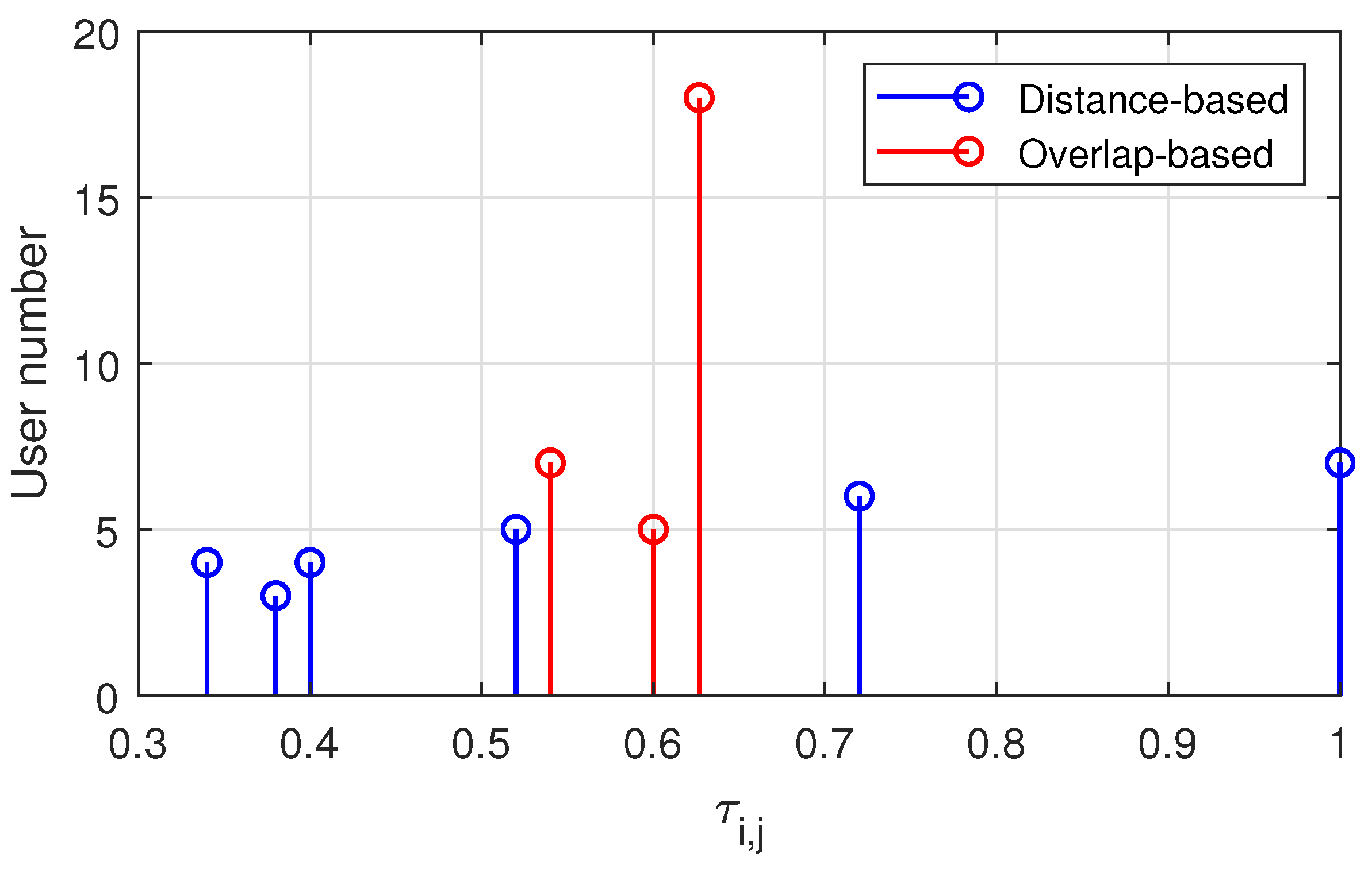
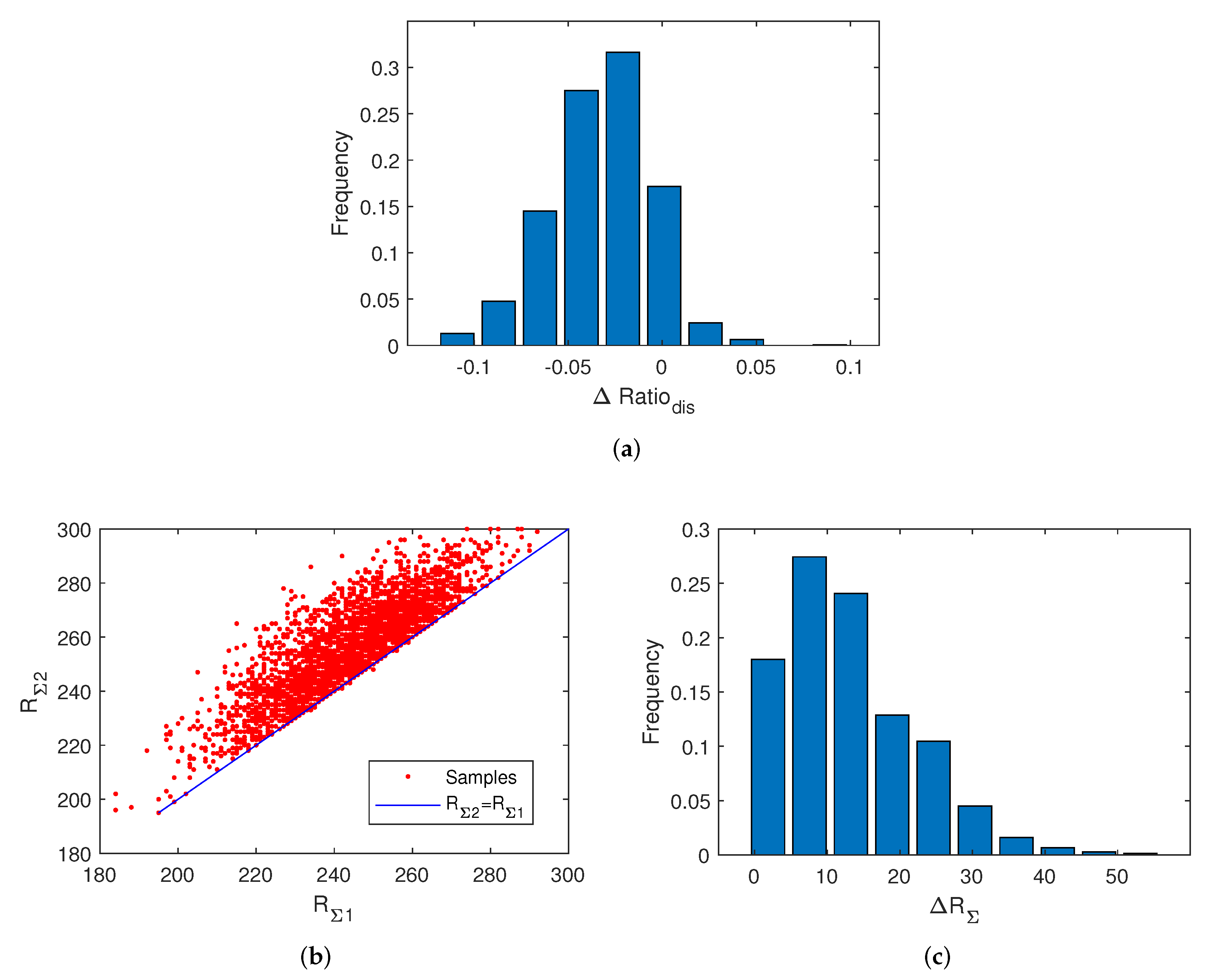
  • Finally, we compare the system performance of the overlap-based scheme and distance-based scheme by simulation. The results show that the overlap-based design reduces the user discarding ratio in the case of extreme user density through the flexible user discard algorithm. Meanwhile, when users are not very intensively distributed, the results indicate that the proposed scheme can increase resource utilization, hence reducing the maximum delay and enhancing the fairness of time delay.
The remainder of our paper is organized as follows. In Section 2, we introduce the integrated system and its time-delay model. Then, we propose the overlap-based low-delay design in Section 3. After that, we present some simulations in Section 4. Finally, we conclude the paper in Section 5.

2. System Model

This section will design a system that integrates computation and transmission. Specifically, we will introduce the overlap-based working mode of the MEC-VLC module. After that, according to IIoT’s application features, we model the downlink time delay and then propose the mathematical criterion of overlap-based design.

2.1. System Configuration

For the construction of the MEC-VLC network, we integrate computing and transmitting functions to form the computing-transmitting unit (CTU), as shown in Figure 1. In CTU, the initial data is first computed in the MEC part and generates the transmitted data. Then, the generated data is modulated and transmitted by light-emitting diodes (LED) in the VLC part. The power distribution of LED follows Lambert model [40].
After the construction of CTU, we establish the computation and transmission integrating system as Figure 2. For downlink transmission, this system has the MEC-VLC module as the main body and the 5G/WiFi module as the supplement. All modules are connected to a control unit through fibers in this system. A monitoring unit timely provides the user distribution, data demand, and other status to the control unit [41]. According to these status data, the control unit manages the task and resource allocation and assigns initial data to computing units or CTUs. When the computing and transmitting resources of MEC-VLC are adequate for all users’ access, only the MEC-VLC module is used. However, if the resources are insufficient, the supplementary module can serve the discarded users through encrypted MEC-5G/WiFi. Note that the complementary module is also used to serve users whose VLC links from all CTUs are blocked by any obstacle. For data uploading, we can adopt infrared communication by integrating the corresponding functions to CTUs and users [42], or we could use 5G/WiFi by multiplexing with the downlink transmission [39].
In this paper, we only introduce the design of the MEC-VLC module in downlink transmission. For the convenience of subsequent description, we denote the i-th CTU as T i ( i = 1 , 2 , , M ) and the j-th users as U j ( j = 1 , 2 , , N ). Meanwhile, users in overlapping or non-overlapping area of adjacent attocells construct the set A k ( k = 1 , 2 , , 2 M 1 ) as Figure 2. Note that if the VLC link from one of the corresponding CTU to U j in an overlapping area is blocked but the user can access the adjacent CTU T i , then we default U j A 2 i 1 .
In the proposed system, it is necessary to judge whether the resources of the MEC-VLC network can support the computation and communication of all users. For a very extreme case where users are so intensive that the resources are insufficient, some users should be discarded by MEC-VLC and served by the supplementary module for congestion avoidance. Based on attocell association, we will judge the probable congestion and develop a user discard strategy.
Under the premise of sufficient resources, CTUs can improve the quality of service by adjusting the cooperative way. Here, the measure of service quality is the system delay. In the MEC-VLC system, adjacent attocells use different frequencies to eliminate inter-attocell interference. Thus, U j in an overlapping area of two attocells, i.e., U j A 2 i ( i = 1 , 2 , , M 1 ), can be simultaneously served by both adjacent CTUs T i and T i + 1 . Hence, their initial data can be offloaded by both CTUs according to the optimized task factor α i , j and α i + 1 , j . Here, α i , j is the proportion of U j ’s tasks assigned to T i , noting that α i , j = 0 if U j is not in the i-th attocell. At the receiving end, data from two CTUs are integrated and then recovered by U j . Then, the initial data for U j is divided into two parts respectively for T i and T i + 1 , and then U j can be equivalent to two users respectively in A 2 i 1 and A 2 i + 1 .
After the task assignment, there is no need to consider attocell overlap anymore. Hence, we will operate the joint resource allocation in a non-overlapping attocell. At CTU, the initial data for users are computed in parallel using the allocated computing resource. The allocation is operated according to the factor β i , j c , which is the ratio of T i ’s computing resources allocated to U j . After computation, users in one attocell are allocated different bandwidths according to the resource allocation factor β i , j t and be served using orthogonal frequency division multiplexing access or frequency division multiple access technologies. Here, β i , j t is the ratio of T i ’s bandwidth allocated to U j .
Consequently, the flow of flexible overlap-based scheme is as shown in Figure 3, which will be described in detail in the following paper.

2.2. Time Delay Model

In this paper, our purpose of the flexible design is to improve the latency performance of the MEC-VLC network. Thus, the time delay of this system should be modeled. In MEC-VLC, the time delay is mainly generated in data computation and transmission. Because fiber bandwidth is far broader than the bandwidth of wireless transmission, the transmission delay in fiber can be ignored. Hence, we respectively model the time delay caused by computing and optical wireless transmission [13,14]. Here, we assume that the initial data for each user is continuously generated. Meanwhile, the frame lengths of users’ initial data are proportional to their data rate, i.e., l j = t 0 r j to make the frames of different users contain the state data of the same period. Here, l j is the frame length of U j ’s initial data, t 0 is a constant period for all users, and r j is U j ’s initial data rate.
Then, the computing time delay of T i for U j ’s task is
t i , j c = α i , j η j l j β i , j c F = t 0 α i , j η j r j β i , j c F = t 0 τ i , j c
where η j is the number of computational operations required for each bit task of U j , and F is the maximum number of computing operations that each CTU can operate per second. Because t 0 is constant, we define the computing delay factor τ i , j c = α i , j η j r j β i , j c F for computing delay measurement. Similarly, the transmission delay of T i for U j ’s task is
t i , j t = α i , j λ j l j β i , j t R = t 0 α i , j λ j r j β i , j t R = t 0 τ i , j t
where λ j l j is frame length of the generated data by computation, and R is the maximum transmitting data rate of each VLC module. We define the transmission delay factor τ i , j t = α i , j λ j r j β i , j t R for transmission delay measurement. Then, the total delay factor is τ i , j = τ i , j c + τ i , j t , which satisfies
τ i , j = τ i , j U j A 2 i 1 max τ i , j , τ i + 1 , j U j A 2 i
According to the idea of flexible allocation and the time delay model, we propose the following criterion of low-delay allocation design.
min α , β c , β t max i , j τ i , j = τ i , j c + τ i , j t s . t . i α i , j = 1 j β i , j c = 1 j β i , j t = 1 τ i , j c , τ i , j t 1 α i , j , β i , j c , β i , j t 0 , 1
To ensure that the overall time delay of users is kept in a certain range, we optimize the factors of task and resource, aiming to minimize the maximum τ i , j . For the constraints, ① ensures that the computing and transmitting tasks of each user are completely accomplished with or without CTU’s cooperation. ② and ③ guarantee that the computing and transmitting resources of each CTU are adequate and fully used. ④, which also means t i , j c , t i , j t t 0 , is used to prevent the congestion of continuous computation and transmission, i.e., the case that computing and transmitting rate are larger than the rate of continuous data download and generation. In this case, the computation or transmission resources cannot support some users’ computing or transmitting tasks, which is called congestion. ⑤ limits the ranges of α i , j , β i , j c and β i , j t because they are all allocation factors.

3. Flexible Design Based on Attocell Overlap

In this section, we perform the overlap-based flexible design based on the above criterion. Before we introduce it, we define the optimizing unit according to users’ distribution in overlapping areas and task allocation to reduce the complexity of the subsequent design.
Definition 1.
Optimizing unit is a set of users which satisfies
Ψ = k = 2 i a 1 2 i b 1 A k
where
i a = 1 or A 2 i a 2 = or α i a 1 , j , U j A 2 i a 1 is optimized i b = M or A 2 i b = or α i b , j , U j A 2 i b is optimized A 2 i for i a i < i b
It is not difficult to get that users in one MEC-VLC system can be divided into several optimizing units. In the following section, we assume that the system’s initial states of both user discard and flexible allocation only contain one optimizing unit (i.e., Ψ = k = 1 2 M 1 A k ) for the convenience of description. For other cases, we can use the same design method in each initial optimizing unit to improve the overall latency performance as much as possible. In addition, although the joint resource allocation is operated at last in practice, we will first introduce it because its result is closely related to the subsequent links.

3.1. Joint Allocation of Computing & Transmission Resources in Single Attocell

We have already mentioned that one user in overlapping areas can be equivalent to two users in non-overlapping areas by task assignment. Therefore, the joint allocation of computing and transmitting resources, which is operated at last, only needs to be considered in a single attocell. Here, we assume that η j = η 0 and λ j = λ 0 for all U j . Under this case, Theorem 1 is satisfied, the proof of which is in Appendix A.
Theorem 1.
In i-th attocell, if the computing and transmitting resources are adequate for its users, i.e.,
j = 1 N α i , j r j min F η 0 + R λ 0
the resource allocation factors
β i , j c = β i , j t = α i , j r j j = 1 N α i , j r j
minimizes the max j τ i , j , and the corresponding delay is τ i = τ i , j = η 0 F + λ 0 R j = 1 N α i , j r j for users in i-th attocell.
According to ① in (4) and considering the fairness of time delay for users in an attocell, we assume that α i ^ = α i , 2 i = 1 α i + 1 , 2 i and α ^ = α ^ 1 α ^ 2 α ^ M 1 T . In both overlapping and none-overlapping areas, the computing and transmitting resources can be allocated in proportion to users’ initial data rates after the task allocation. Hence, according to Theorem 1, A k can be regarded as a user with the initial data rate of R k = U j A k r j . Therefore, the MEC-VLC module in Figure 2 can be converted to Figure 4, which will be adopted in following analysis. The delay factors of users served by T i can all be denoted as τ i .

3.2. Attocell-Associated Congestion Judgement & User Discard for Congestion Avoidance

After equating A k to a single user in overlapping or non-overlapping areas, we consider the attocell-associated congestion judgment and user discard for congestion avoidance. According to Theorem 1, when CTUs download the initial data due to the task allocation factors, the total delay factor of each attocell can be presented as
τ 1 τ 2 τ M 1 τ M T = η 0 F + λ 0 R γ 1 γ 2 γ M 1 γ M T
where the equivalent total data rates for each attocell are
γ 1 = R 2 0 0 0 0 α ^ + R 1 = v 1 T α ^ + u 1 γ 2 = R 2 R 4 0 0 0 α ^ + R 2 + R 3 = v 2 T α ^ + u 2 γ M 1 = 0 0 0 R 2 M 4 R 2 M 2 α ^ + R 2 M 4 + R 2 M 3 = v M 1 T α ^ + u M 1 γ M = 0 0 0 0 R 2 M 2 α ^ + R 2 M 2 + R 2 M 1 = v M T α ^ + u M
Due to ④ in (4), the following relationship should be satisfied.
γ i R 0 , i
where R 0 = min F η 0 , R λ 0 . Then we can get the Theorem 2, the proof of which is in Appendix B.
Theorem 2.(5) is equivalent to
k = j j + i 1 R k i + 1 2 R 0 , i = 1 , 3 , , 2 M 1 j = 1 , 3 , , 2 M i
which ensures that no congestion will occur.
According to Theorem 2, we can judge whether resources are adequate for users. Aiming at making the congestion impossible, we propose Algorithm 1 for congestion avoidance in the case that resources are not sufficient. The main principle is to reduce the number of discarded users and the loss of initial data as much as possible. After this algorithm runs, all A k are updated, making congestion impossible. It is not difficult to get that the algorithm requires M 1 + M 2 times of judgement.
Algorithm 1 User discard for congestion avoidance
1:
for ( i 0 1 ; i 0 2 M 1 ; i 0 i 0 + 2 ) do
2:
     for ( j 0 1 ; j 0 2 M i 0 ; j 0 j 0 + 2 ) do
3:
         δ = k = j 0 j 0 + i 0 1 R k i 0 + 1 2 R 0
4:
        while δ >0 do
5:
           if max j r j < δ for U j k = i 0 j 0 A k  then
6:
                 Discard U j corresponding to max j r j for U j k = i 0 j 0 A k ;
7:
           else
8:
                 Discard U j corresponding to min j r j r j δ for U j k = i 0 j 0 A k ;
9:
           end if
10:
        end while
11:
     end for
12:
end for
13:
Refresh all A k according to the discarded users;

3.3. Overlap-Based Task Assignment

In the above contents, we have got the equivalent model of multi-users and have ensured that the congestion is prevented. Next, we will discuss the overlap-based task allocation scheme. When the resource allocation factors are set as Theorem 1, the optimization of total delay factors via α ^ as (4) can be converted to
arg min α ^ max i γ i s . t . A α ^ b
where, A = I M 1 I M 1 V and b = 1 M 1 × 1 0 M 1 × 1 R 0 1 M × 1 u . Here,
V = v 1 v 2 v M T = R 2 R 2 R 4 R 4 R 2 M 4 R 2 M 4 R 2 M 2 R 2 M 2 T
u = u 1 u 2 u M T = R 1 R 2 + R 3 R 4 + R 5 R 2 M 2 + R 2 M 1 T
Then, there is Theorem 3 according to [43].
Theorem 3.
After user discard and user equivalence, the optimization of α ^ is equivalent to the following linear programming problem
arg min z c ^ z s . t . A ^ z b ^
where z = α ^ y , c ^ = 0 1 , A ^ = A 0 V 1 M × 1 and b ^ = b u . If z * = α ^ * y * is the optimization result, then α ^ * is the best α ^ , and y * η 0 F + λ 0 R is the min α ^ max i τ i .
Here, (8) can be easily solved by the linear programming, and thus the task allocation factor is optimized. However, this method only minimizes the maximum total delay factor in an optimizing unit but is invalid for other users with smaller delay factors. Therefore, we consider optimizing the overall delay factors by subdivision of optimizing unit and iterative optimization, as shown in Algorithm 2.
Algorithm 2 Iterative optimization of α ^
1:
Initialize α ^ * = 0 ;
2:
Divide the system or the optimizing unit into several optimizing units;
3:
for Each divided optimizing unit do
4:
     Calculate α * ^ and y * according to Theorem 3;
5:
      Δ = V α ^ * + u y *
6:
     Find the location of zero elements in Δ and construct them into a set i
7:
     for i i and T i corresponds to the optimizing unit do
8:
        if T i is the first CTU corresponding to the optimizing unit then
9:
           if Δ i + 1 = Δ i or ( Δ i + 1 < Δ i and α ^ i * = 0 ) then
10:
             Mark that α ^ i * is optimized;
11:
          end if
12:
       else if T i is the last CTU corresponding to the optimizing unit
13:
          if Δ i 1 = Δ i or ( Δ i 1 < Δ i and α ^ i 1 * = 1 ) then
14:
             Mark that α ^ i 1 * is optimized;
15:
          end if
16:
       else
17:
          if ( Δ i + 1 = Δ i or ( Δ i + 1 < Δ i and α ^ i * = 0 )) and ( Δ i 1 = Δ i or ( Δ i 1 < Δ i and α ^ i 1 * = 1 )) then
18:
             Mark that α ^ i 1 * and α ^ i * are optimized;
19:
          end if
20:
       end if
21:
     end for
22:
     if α ^ i * of the optimizing unit are not all optimized then return 2
23:
        return 2
24:
     end if
25:
end for
In Algorithm 2, we first optimize α ^ in the first divided optimizing unit. According to the optimized delay factors, we judge whether any element of α ^ can be further optimized. The main idea of the judgment is to figure out whether the CTU with a shorter delay is allocated the task as much as possible. As in lines 8–21 of the algorithm, if the task allocation factor makes users in two adjacent attocells have the same delay factors, then the factor can be considered optimal. Another optimal case is that the delay of the attocell is larger than the adjacent one, although all tasks have been allocated to the adjacent one. After that, the subdivision of optimizing unit and optimization will be carried out until no more elements can be further optimized to get the overall optimizing result. Because the computational complexity of interior point method algorithm is O M 3.5 , the maximum computational complexity is O M 4.5 [44]. In practice, the complexity could be greatly decreased by division of optimizing unit.

4. Simulation

In this section, we verify the improvement of delay factors and user discard performance of the overlap-based design. The main parameters of VLC at both transmitter and receiver are shown in Table 1. Our pre-simulations have demonstrated that if the diameter of attocells is 6 m, it can be ensured that the BER of users at any location in each attocell is not greater than 10 4 . Note that to avoid into-attocell communication interference, only half of the total bandwidth is used because of the frequency division multiplexing access with adjacent transmitters.
The following simulations are all operated in the system, as shown in Figure 2, where we place six CTUs on a straight line with the same interval D. N users randomly distribute in the six corresponding attocells, obeying uniform distribution. The initial data rate of each user also satisfies a discrete uniform distribution. Other parameters related to the intensive attocell system are listed in Table 2.
In these simulations, we compare the performance of overlap and distance-based design. In distance-based design, the coverage of each CTU are bounded by centerlines between adjacent CTUs. For users in each coverage, if the resources are not sufficient, user discard will also be operated following lines 4–9 in Algorithm 1. After that, resource allocation are carried out in each coverage as Theorem 1; For overlap-based design, all links are operated using the proposed attocell-associated schemes.

4.1. Design Example

First, we take a design example of both design strategies to visually present their ideas and performance. In Figure 5, the green circles are the boundaries of attocells, and the orange triangles are CTUs. Additionally, the points are users with their initial data rate marked beside them, where the MEC-VLC module serves the blue points while the red ones are discarded and served by supplementary module. As we can see, under the same condition, there is one discarded user in the distance-based design while no user is discarded under the overlap-based design. The results indicate that the attocell-associated design provides more options for user access and reduce the user discard ratio.
After user discard, task assignment and resource allocation are operated. In the distance-based design, users’ tasks are divided by the pink center lines. However, in the overlap-based scheme, tasks are adaptively allocated to adjacent CTUs, and the best task allocation factors are
α ^ * = 0 . 1667 1 . 0000 1 . 0000 0 . 0333 0 . 4667 T
Meanwhile, for both methods, the resource allocation are proportional to r j in each attocell.
Figure 6 is the distribution of τ in both methods. Here, the horizontal axis represents the values of delay factor for users in the system, and the vertical axis is the user number for each τ i , j . As we can see, when using overlap-based allocation, the maximum τ is less and the distribution is more concentrated, i.e., the flexible design performs better on the control of maximum delay and the service fairness.

4.2. Statistical Research

4.2.1. Decrease of User Discard

Next, we explore the performance gain of the proposed scheme using statistical methods. In Figure 7a, we compare the user discard ratio when using two schemes. Here, we temporarily set N = 50 to generate more discarded users. We measure the performance using the user discard ratio and the total initial data rate of the remaining users. Note that for the convenience of description, we use subscript 1 to represent the result of distance-based design and subscript 2 for overlap-based design in follows. The results in Figure 7a demonstrate that our method has a 78.7% probability of reducing the number of discarded users and a 3.6% possibility of increasing it. On average, the overlap-based design keeps 1.5 users from being discarded. Meanwhile, as shown in Figure 7b,c, the overlap-based scheme has a 96.0% chance of increasing the total rate compared with the distance-based design, and the average total rate is increased by 13 Mbps. Consequently, because of users’ flexible access in overlap-based design, the user discard ratio decreases and the resource utilization rate improves, which illustrates that the proposed strategy has enhanced the system reliability and service quality.

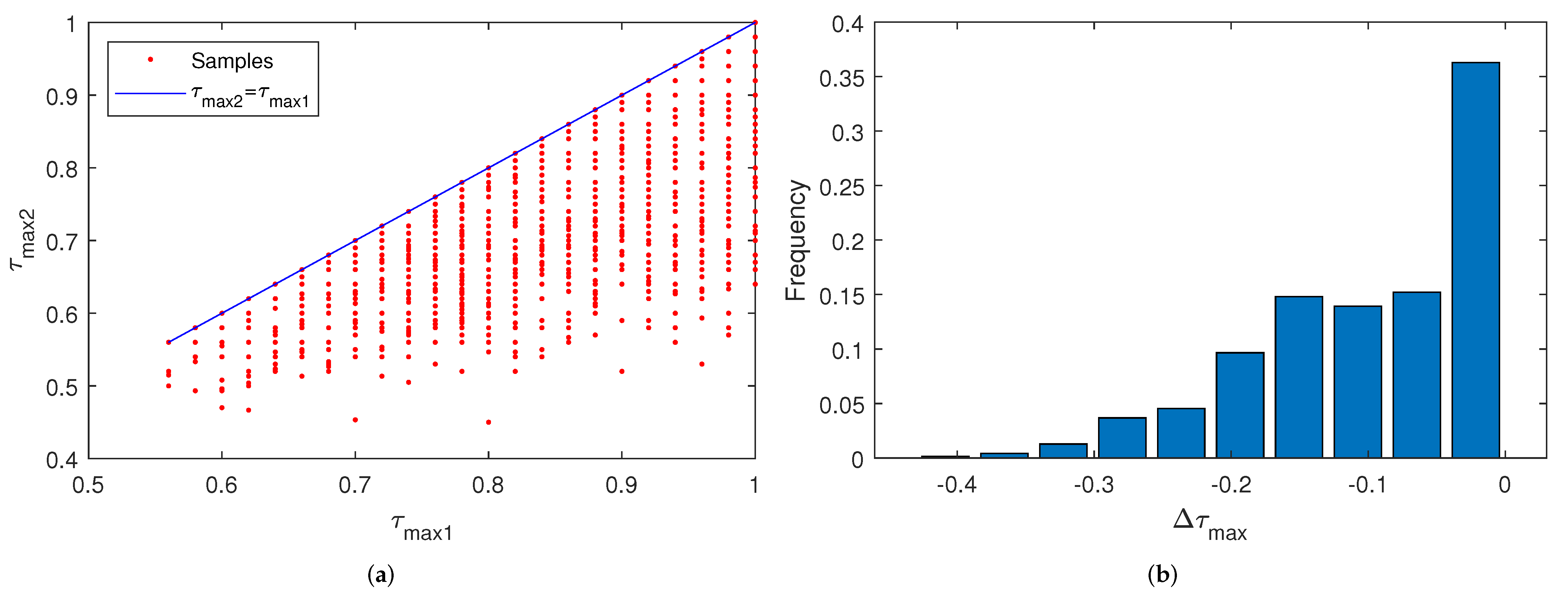
4.2.2. Reduction of Delay Factors

Next, we compare the statistical characteristics of users’ delay factors τ under both methods. Here, N = 30 , and for ease of comparison fairness, we only consider the case when no user is discarded in both methods.
Figure 8a is the maximum τ under two schemes, where red points are the simulated results. As we can see, the red points are always below the blue line, which represents τ max 2 = τ max 1 , i.e., the overlap-based design always has less τ max than the distance-based design. Figure 8b is the frequency distribution histogram of Δ τ max , which also demonstrates that Δ τ max 0 . Meanwhile, our statistical results show that the proposed scheme can reduce the maximum delay factors by 11.2% on average. In other words, the overlap-based task assignment and joint resource allocation effectively control the time delay by CTU’s flexible cooperation and utilization modes.
Figure 9a is the mean of delay factors τ mean under two schemes and Figure 9b is the frequency distribution histogram of Δ τ mean . The simulation results demonstrate that the overlap-based design has a probability of 69.0% to reduce the mean delay and 31.0% to increase it. Overall, the mean of Δ τ mean is −0.0126. In other words, the overlap-based scheme targeting maximum delay can improve the time delay distribution, but its enhancement on the average delay is not very obvious. This is because the proposed resource assignment scheme does not increase the total amount of computation and transmission resources. The scheme can only adjust the delay distribution among different users. If some users with larger delays are assigned more resources, other users with shorter delays will be given fewer resources leading to their delay increase.
Figure 10a is the standard deviation of delay factors τ σ under two schemes and Figure 10b is the frequency distribution histogram of Δ τ σ . According to both figures and the statistical results, the overlap-based design has a probability of 95.6% to reduce τ σ . It can decrease 29.5% τ σ on average, which verifies the improvement of the iterative optimization on the overall delay and indicates that the proposed scheme could enhance the fairness of user service.

5. Conclusions

In this paper, we proposed an MEC-VLC integrating network to realize low-delay computation and transmission in IIoT. Due to the attocell overlap caused by the intensively arranged CTUs, users in overlapping areas can choose to access one or two adjacent CTUs, increasing flexibility and enhancing the delay performance. In the defined optimizing units, user discard was carried out for congestion avoidance. After that, we operated task assignments to decrease time delay. Finally, the computing and transmitting resources were jointly allocated. Our simulations demonstrated that compared with the distance-based design, the user discard algorithm based on attocell overlap reduces user discard rate owing to the flexible access. Meanwhile, it was also illustrated that the proposed scheme decreases the overall delay and enhances user fairness through flexible CTU cooperation and resource allocation.

Author Contributions

Conceptualization, J.X. and Y.Z.; methodology, J.X.; validation, J.X.; formal analysis, J.X.; writing—original draft preparation, J.X.; writing—review and editing, Y.Z., Z.Y. and H.Z. All authors have read and agreed to the published version of the manuscript.

Funding

The research of this paper was funded in part by the National Key Research and Development Project under Grant No. 2018YFB1801903, in part by the National Natural Science Foundation of China (NSFC) under Grant 61901524 and in part by the China Postdoctoral Science Foundation under Grant No. 2019M663477.

Acknowledgments

The authors wish to thank the anonymous reviewers for their valuable suggestions.

Conflicts of Interest

The authors declare no conflict of interest.

Appendix A. Proof of Theorem 1

Considering the case when M = 1 and N = 2 , there is α = 1 1 . The criterion of (4) converts to
min α , β c , β t max η 0 r 1 β 1 , 1 c F + λ 0 r 1 β 1 , 1 t R , η 0 r 2 β 1 , 2 c F + λ 0 r 2 β 1 , 2 t R s . t . β 1 , 1 c + β 1 , 2 c = 1 β 1 , 1 t + β 1 , 2 t = 1 η 0 r 1 F β 1 , 1 c 1 η 0 r 1 F λ 0 r 1 R β 1 , 1 t 1 λ 0 r 1 R
Setting
β 1 , 1 c = r 1 r 1 + r 2 , β 1 , 1 t = r 1 r 1 + r 2 β 1 , 2 c = r 2 r 1 + r 2 , β 1 , 2 t = r 2 r 1 + r 2
which satisfies the constraints, we can get that
τ 1 , 1 = τ 1 , 2 = η 0 F + λ 0 R r 1 + r 2
and we set τ 0 = η 0 F + λ 0 R r 1 + r 2 . Next, we discuss two cases:
  • If
    β 1 , 1 c = r 1 r 1 + r 2 + δ , β 1 , 1 t = r 1 r 1 + r 2 β 1 , 2 c = r 2 r 1 + r 2 δ , β 1 , 2 t = r 2 r 1 + r 2
    where δ 0 , r 2 r 1 + r 2 η 0 r 1 F , it is not difficult to get that τ 1 , 1 < τ 0 and τ 1 , 2 > τ 0 , which means the maximum τ is larger. If δ η 0 r 1 F r 1 r 1 + r 2 , 0 , then τ 1 , 1 > τ 0 and τ 1 , 2 < τ 0 . Thus, δ = 0 minimizes the delay factor. Similarly, separate change of β 1 , j t also increases the delay.
  • If
    β 1 , 1 c = r 1 r 1 + r 2 + δ 1 , β 1 , 1 t = r 1 r 1 + r 2 δ 2 β 1 , 2 c = r 2 r 1 + r 2 δ 1 , β 1 , 2 t = r 2 r 1 + r 2 + δ 2
    where δ 1 0 , r 2 r 1 + r 2 η 0 r 1 F and δ 2 max 0 , λ 0 r 1 R r 2 r 1 + r 2 , r 1 r 1 + r 2 λ 0 r 1 R , then
    τ 1 , 1 τ 0 τ 1 , 2 τ 0 F η 0 1 δ 1 + 1 + r 2 r 1 R λ 0 1 δ 2 1 r 2 r 1 F η 0 1 δ 1 r 1 r 2 1 R λ 0 1 δ 2 + r 1 r 2 + 1
    Thus, R λ 0 + F η 0 0 , which is unreasonable. Thus, (A1) is the optimal solution.
For the case when N 2 , it is not difficult to get analogous results, and thus Theorem 1 is proved.

Appendix B. Proof of Theorem 2

1
(5) ⇒ (6): Due to 0 α ^ i 1 , (6) can be easily obtained by combining (5).
2
(6) ⇒ (5): In an optimizing unit, A 2 i , so
γ 1 R 0 γ i R 0 γ M R 0 α ^ 1 R 0 R 1 R 2 α ^ 1 R 2 + R 3 + α ^ 2 R 4 R 0 R 2 α ^ i R 2 i + R 2 i + 1 + α ^ i + 1 R 2 i + 2 R 0 R 2 i α ^ M 2 R 2 M 4 + R 2 M 3 + α ^ M 1 R 2 M 2 R 0 R 2 M 4 α ^ M 1 R 2 M 1 + R 2 M R 0 R 2 M 1 α ^ 1 R 0 R 1 R 2 α ^ 2 α ^ 1 R 2 R 2 R 3 + R 0 R 4 α ^ i α ^ i 1 R 2 i 2 R 2 i 2 R 2 i 1 + R 0 R 2 i α ^ M 1 α ^ M 2 R 2 M 4 R 2 M 4 R 2 M 3 + R 0 R 2 M 2 α ^ M 1 R 2 M 2 + R 2 M 1 R 0 R 2 M 2
Meanwhile, by combining two equivalent formations, we can get another equivalent equation.
2 2 M 1 R i M 1 R 0 R 2 α ^ 1 R 0 R 1 R 2 4 2 M 1 R i M 2 R 0 R 4 α ^ 2 α ^ 1 R 2 R 2 R 3 + R 0 R 4 2 i 2 M 1 R i M i R 0 R 2 i α ^ i α ^ i 1 R 2 i 2 R 2 i 2 R 2 i 1 + R 0 R 2 i R 2 M 2 + R 2 M 1 R 0 R 2 M 2 α ^ M 1 α ^ M 2 R 2 M 4 R 2 M 4 R 2 M 3 + R 0 R 2 M 2
Under the condition that (6) is workable, if for α ^ 1 0 , 1 , the first inequality in (A3) is not satisfied, then there are three probable cases.
  • 2 2 M 1 R i M 1 R 0 R 2 > 1 3 2 M 1 R i > M 1 R 0
  • R 0 R 1 R 2 < 0 R 1 > R 0
  • 2 2 M 1 R i M 1 R 0 R 2 > R 0 R 1 R 2 1 2 M 1 R i > M R 0
All of them conflict with (6), i.e., α ^ 1 0 , 1 makes the first inequality in (A3) workable. Then, if for α ^ 2 0 , 1 , the second inequality in (A3) is not satisfied, then there are three probable cases.
  • 4 2 M 1 R i M 2 R 0 R 4 > 1 5 2 M 1 R i > M 2 R 0
  • α ^ 1 R 2 R 2 R 3 + R 0 R 2 2 R 0 1 3 R i R 2 < 0 1 3 R i > 2 R 0
  • 4 2 M 1 R i M 2 R 0 R 4 > α ^ 1 R 2 R 2 R 3 + R 0 R 4 4 2 M 1 R i M 2 R 0 R 4
All of these cases are impossible under the premise, i.e, α ^ 2 0 , 1 makes the second inequality in (A3) workable. For α ^ i 0 0 , 1 ( i 0 = 2 , 3 , , or M 1 ), if the i 0 -th inequality in (A3) is not satisfied but α ^ i 0 , 1 ( i = 1 , 2 , , and i 0 1 ) make the i-th inequality of (A3) workable, then there are three probable cases.
  • 2 i 0 2 M 1 R i M i 0 R 0 R 2 i 0 > 1 2 i 0 + 1 2 M 1 R i > M i 0 R 0
  • α ^ i 0 1 R 2 i 0 2 R 2 i 0 2 R 2 i 0 1 + R 0 R 2 i 0 i 0 R 0 1 2 i 0 1 R i R 2 i 0 < 0 1 2 i 0 1 R i > i 0 R 0
  • 2 i 0 2 M 1 R i M i 0 R 0 R 2 i 0 > α ^ i 0 1 R 2 i 0 2 R 2 i 0 2 R 2 i 0 1 + R 0 R 2 i 0 2 i 0 2 M 1 R i M i 0 R 0 R 2 i 0
It is not difficult to get that the assumption is not workable. To sum up, when (5) is satisfied, α ^ i 0 , 1 ( i = 1 , 2 , , M 1 ) which make (5) workable.

References

  1. Moer, W.V. Industry 4.0 and IoT [Editorial]. IEEE Instrum. Meas. Mag. 2018, 21, 2. [Google Scholar] [CrossRef]
  2. Durocher, D. Industry 4.0 [From the Editor’s Desk]. IEEE Ind. Appl. Mag. 2019, 25, 3–78. [Google Scholar] [CrossRef]
  3. Su, S.F.; Rudas, I.J.; Zurada, J.M.; Er, M.J.; Chou, J.H.; Kwon, D. Industry 4.0: A special section in IEEE access. IEEE Access 2017, 5, 12257–12261. [Google Scholar] [CrossRef] [Green Version]
  4. Khalil, R.A.; Saeed, N. Network Optimization for Industrial Internet of Things (IIoT). IEEE Sensors Lett. 2020, 4, 1–4. [Google Scholar] [CrossRef]
  5. Liu, W.; Nair, G.; Li, Y.; Nesic, D.; Vucetic, B.; Poor, H.V. On the Latency, Rate, and Reliability Tradeoff in Wireless Networked Control Systems for IIoT. IEEE Int. Things J. 2021, 8, 723–733. [Google Scholar] [CrossRef]
  6. Mumtaz, S.; Bo, A.; Al-Dulaimi, A.; Tsang, K.F. Guest editorial 5G and beyond mobile technologies and applications for industrial IoT (IIoT). IEEE Trans. Ind. Inform. 2018, 14, 2588–2591. [Google Scholar] [CrossRef]
  7. Fernández, F.; Zverev, M.; Garrido, P.; Juárez, J.R.; Bilbao, J.; Agüero, R. Even lower latency in iiot: Evaluation of quic in industrial iot scenarios. Sensors 2021, 21, 5737. [Google Scholar] [CrossRef] [PubMed]
  8. Khan, F.; Jan, M.A.; Rehman, A.U.; Mastorakis, S.; Alazab, M.; Watters, P. A Secured and Intelligent Communication Scheme for IIoT-enabled Pervasive Edge Computing. IEEE Trans. Ind. Inform. 2021, 17, 5128–5137. [Google Scholar] [CrossRef]
  9. Du, P.; Zhang, S.; Alphones, A.; Chen, C. Faster Deployment for Indoor Visible Light Positioning Using Xgboost Algorithms in Industrial Internet-of-Things. In Proceedings of the IECON 2021—47th Annual Conference of the IEEE Industrial Electronics Society, Toronto, ON, Canada, 13–16 October 2021; pp. 1–7. [Google Scholar] [CrossRef]
  10. Kim, Y.; Lee, H.W.; Chong, S. Mobile Computation Offloading for Application Throughput Fairness and Energy Efficiency. IEEE Trans. Wirel. Commun. 2019, 18, 3–19. [Google Scholar] [CrossRef]
  11. Althoubi, A.; Alshahrani, R.; Peyravi, H. Delay analysis in iot sensor networks. Sensors 2021, 21, 3876. [Google Scholar] [CrossRef]
  12. Li, F.; Guo, Z.; Liang, B.; Yi, X.; Wang, X.; Li, W.; Wang, Y. A measurement study on device-to-device communication technologies for IIoT. Comput. Netw. 2021, 192, 108072. [Google Scholar] [CrossRef]
  13. Emara, M.; Filippou, M.C.; Sabella, D. MEC-aware cell association for 5G heterogeneous networks. In Proceedings of the 2018 IEEE Wireless Communications and Networking Conference Workshops (WCNCW), Barcelona, Spain, 15–18 April 2018; pp. 350–355. [Google Scholar] [CrossRef] [Green Version]
  14. Le, H.Q.; Al-Shatri, H.; Klein, A. Efficient resource allocation in mobile-edge computation offloading: Completion time minimization. In Proceedings of the 2017 IEEE International Symposium on Information Theory (ISIT), Aachen, Germany, 25–30 June 2017; pp. 2513–2517. [Google Scholar] [CrossRef]
  15. Yu, H.; Wang, Q.; Guo, S. Energy-efficient task offloading and resource scheduling for mobile edge computing. In Proceedings of the 2018 IEEE International Conference on Networking, Architecture and Storage (NAS), Chongqing, China, 11–14 October 2018; pp. 1–4. [Google Scholar] [CrossRef]
  16. Yang, S. A joint optimization scheme for task offloading and resource allocation based on edge computing in 5G communication networks. Comput. Commun. 2020, 160, 759–768. [Google Scholar] [CrossRef]
  17. Cao, J.; Yang, L.; Cao, J. Revisiting computation partitioning in future 5G-based edge computing environments. IEEE Int. Things J. 2019, 6, 2427–2438. [Google Scholar] [CrossRef]
  18. Pang, F.; Wu, X. A Win-win mode: The complementary and coexistence of 5g networks and edge computing. IEEE Int. Things J. 2021, 8, 3983–4003. [Google Scholar] [CrossRef]
  19. Hassan, N.; Yau, K.L.A.; Wu, C. Edge computing in 5G: A review. IEEE Access 2019, 7, 127276–127289. [Google Scholar] [CrossRef]
  20. Rehman, S.U.; Ullah, S.; Chong, P.H.J.; Yongchareon, S.; Komosny, D. Visible light communication: A system perspective—Overview and challenges. Sensors 2019, 19, 1153. [Google Scholar] [CrossRef] [Green Version]
  21. Riurean, S. A study on the VLC security at the physical layer for two indoor scenarios. MATEC Web Conf. 2021, 342, 05009. [Google Scholar] [CrossRef]
  22. Xu, K.; Yu, H.; Zhu, Y.J. Channel-adapted spatial modulation for massive MIMO visible light communications. IEEE Photonics Technol. Lett. 2016, 28, 2693–2696. [Google Scholar] [CrossRef]
  23. Xie, E.; He, X.; Islim, M.S.; Purwita, A.A.; Mckendry, J.; Gu, E.; Haas, H.; Dawson, M. High-Speed Visible Light Communication Based on a III-Nitride Series-Biased Micro-LED Array. J. Light. Technol. 2019, 37, 1180–1186. [Google Scholar] [CrossRef] [Green Version]
  24. Al-Ahmadi, S.; Maraqa, O.; Uysal, M.; Sait, S.M. Multi-user visible light communications: State-of-the-art and future directions. IEEE Access 2018, 6, 70555–70571. [Google Scholar] [CrossRef]
  25. Feng, S.; Zhang, R.; Xu, W.; Hanzo, L. Multiple access design for ultra-dense VLC networks: Orthogonal vs non-orthogonal. IEEE Trans. Commun. 2019, 67, 2218–2232. [Google Scholar] [CrossRef] [Green Version]
  26. Xu, J.; Gong, C.; Luo, J.; Xu, Z. LED Half-Power Angle Optimization for Ultra-Dense Indoor Visible Light Communication Network Deployment. IEEE Open J. Commun. Soc. 2020, 1, 835–848. [Google Scholar] [CrossRef]
  27. Akbar, A.; Jangsher, S.; Bhatti, F.A. NOMA and 5G emerging technologies: A survey on issues and solution techniques. Comput. Netw. 2021, 190, 107950. [Google Scholar] [CrossRef]
  28. Soua, R.; Turcanu, I.; Adamsky, F.; Führer, D.; Engel, T. Multi-access edge computing for vehicular networks: A position paper. In Proceedings of the 2018 IEEE Globecom Workshops (GC Wkshps), Abu Dhabi, United Arab Emirates, 9–13 December 2018; pp. 1–6. [Google Scholar] [CrossRef] [Green Version]
  29. Loske, M.; Rothe, L.; Gertler, D.G. Context-aware authentication: State-of-the-art evaluation and adaption to the IIoT. In Proceedings of the 2019 IEEE 5th World Forum on Internet of Things (WF-IoT), Limerick, Ireland, 15–18 April 2019; pp. 64–69. [Google Scholar] [CrossRef]
  30. Varga, P.; Peto, J.; Franko, A.; Balla, D.; Haja, D.; Janky, F.; Soos, G.; Ficzere, D.; Maliosz, M.; Toka, L. 5g support for industrial iot applications—Challenges, solutions, and research gaps. Sensors 2020, 20, 828. [Google Scholar] [CrossRef] [PubMed] [Green Version]
  31. Vimal, S.; Khari, M.; Dey, N.; Crespo, R.G.; Robinson, Y.H. Enhanced resource allocation in mobile edge computing using reinforcement learning based MOACO algorithm for IIOT. Comput. Commun. 2020, 151, 355–364. [Google Scholar] [CrossRef]
  32. Lin, Z.; Liu, J.; Xiao, J.; Zi, S. A Survey: Resource Allocation Technology Based on Edge Computing in IIoT. In Proceedings of the 2020 International Conference on Communications, Computing, Cybersecurity, and Informatics (CCCI), Sharjah, United Arab Emirates, 3–5 November 2020; pp. 1–5. [Google Scholar] [CrossRef]
  33. Yu, P.; Yang, M.; Xiong, A.; Ding, Y.; Li, W.; Qiu, X.; Meng, L.; Kadoch, M.; Cheriet, M. Intelligent-Driven Green Resource Allocation for Industrial Internet of Things in 5G Heterogeneous Networks. IEEE Trans. Ind. Inf. 2022, 18, 520–530. [Google Scholar] [CrossRef]
  34. Qiu, T.; Zhang, S.; Si, W.; Cao, Q.; Atiquzzaman, M. A 3-D Topology Evolution Scheme with Self-Adaption for Industrial Internet of Things. IEEE Int. Things J. 2021, 8, 9473–9483. [Google Scholar] [CrossRef]
  35. Chen, Z.; Basnayaka, D.A.; Wu, X.; Haas, H. Interference mitigation for indoor optical attocell networks using an angle diversity receiver. J. Light. Technol. 2018, 36, 3866–3881. [Google Scholar] [CrossRef] [Green Version]
  36. Kashef, M.; Abdallah, M.; Qaraqe, K. Power allocation for downlink multi-user SC-FDMA visible light communication systems. In Proceedings of the 2015 49th Annual Conference on Information Sciences and Systems (CISS), Baltimore, MD, USA, 18–20 March 2015; pp. 1–5. [Google Scholar] [CrossRef]
  37. Bao, X.; Zhu, X.; Song, T.; Ou, Y. Protocol design and capacity analysis in hybrid network of visible light communication and OFDMA systems. IEEE Trans. Veh. Technol. 2014, 63, 1770–1778. [Google Scholar] [CrossRef]
  38. Tang, T.; Shang, T.; Li, Q. Impact of multiple shadows on visible light communication channel. IEEE Commun. Lett. 2020, 25, 513–517. [Google Scholar] [CrossRef]
  39. Yang, H.; Alphones, A.; Zhong, W.D.; Chen, C.; Xie, X. Learning-based energy-efficient resource management by heterogeneous RF/VLC for ultra-reliable low-latency industrial IoT networks. IEEE Trans. Ind. Inform. 2019, 16, 5565–5576. [Google Scholar] [CrossRef]
  40. Chen, H.; Xu, Z. OLED panel radiation pattern and its impact on VLC channel characteristics. IEEE Photonics J. 2017, 10, 1–10. [Google Scholar] [CrossRef]
  41. Hussain, T.; Muhammad, K.; Ser, J.D.; Baik, S.W.; Albuquerque, V.H.C.D. Intelligent Embedded Vision for Summarization of Multiview Videos in IIoT. IEEE Trans. Ind. Inf. 2020, 16, 2592–2602. [Google Scholar] [CrossRef]
  42. Keskin, M.F.; Erdem, O.; Gezici, S. Cooperative Localization in Hybrid Infrared/Visible Light Networks: Theoretical Limits and Distributed Algorithms. IEEE Trans. Signal Inf. Process. Over Netw. 2019, 5, 181–197. [Google Scholar] [CrossRef] [Green Version]
  43. Chong, E.K.; Zak, S.H. An Introduction to Optimization; John Wiley & Sons: Hoboken, NJ, USA, 2004. [Google Scholar]
  44. Ye, Y. Interior Point Algorithms: Theory and Analysis; John Wiley & Sons: Hoboken, NJ, USA, 2011; Volume 44. [Google Scholar]
Figure 1. Diagram of CTU structure.
Electronics 11 00924 g001
Figure 2. Diagram of downlink computation and transmission integrating system.
Electronics 11 00924 g002
Figure 3. Flow diagram of flexible design based on attocell overlap.
Electronics 11 00924 g003
Figure 4. Diagram of users in single attocell.
Electronics 11 00924 g004
Figure 5. (a) System diagram of distance-based design. (b) System diagram of overlap-based design.
Electronics 11 00924 g005
Figure 6. Distribution of total delay factors under distance-based and overlap-based design.
Electronics 11 00924 g006
Figure 7. (a) Frequency distribution histogram of the difference of user discard ratio between two schemes Δ Ratio dis = Ratio dis 2 Ratio dis 1 . (b) Total initial data rate after user discard under two schemes. (c) Frequency distribution histogram of Δ R Σ = R Σ 2 R Σ 1 .
Electronics 11 00924 g007
Figure 8. (a) Maximum delay factor τ max using distance-based scheme and overlap-based scheme. (b) Increase of maximum delay factor Δ τ max = τ max 2 τ max 1 .
Electronics 11 00924 g008
Figure 9. (a) Mean of delay factor τ mean using distance-based criterion and overlap-based criterion. (b) Increase of mean delay factor Δ τ mean = τ mean 2 τ mean 1 .
Electronics 11 00924 g009
Figure 10. (a) Standard deviation of delay factor τ max using distance-based criterion and overlap-based criterion. (b) Increase of standard deviation of delay factor Δ τ σ = τ σ 2 τ σ 1 .
Electronics 11 00924 g010
Table 1. Simulation setup for VLC.
VariateSymbolValue
Total bandwidth of each transmitter-200 [Mbps]
Location of transmitter-(0, 0, 3) [m]
Transmitting power P 0 25 [W]
Semi-angle of half power ψ h 45 [ ]
Modulation-On-off keying
Data rateR50 [Mbps]
Detecting area A r 100 [ mm 2 ]
Photon detector’s responsivity C s 0.64 [A/W]
Equivalent noise power- 2.8 × 10 15 [W/Hz 0.5 ]
Receiver’s location- x , 0 , 0 [m]
Table 2. Simulation setup about the overlap-based system.
CategoryParameterSymbolValue
CTUIntervalD4 [m]
NumberM6
Computing capacityF 10 5 [cycles/second]
Transmitting capacityR50 [Mbps]
Attocell diameter-6 [m]
UsersOriginal user numberN30
Distribution of initial data rate- r j U 0 , 10 [Mbps]
Computation cycles per bit η 0 1000 [cycles/bit]
Calculation result output ratio λ 0 0.5
Publisher’s Note: MDPI stays neutral with regard to jurisdictional claims in published maps and institutional affiliations.

