Article

A New Detection Method for Load Side Broken Conductor Fault Based on Negative to Positive Current Sequence

by
Ali G. Al-Baghdadi
1,*,
Mohammed Kdair Abd
1 and
Firas M. F. Flaih
2,*
1
Department of Electrical Engineering, University of Technology—Iraq, Baghdad 10066, Iraq
2
State Company of North Distribution Electricity, Ministry of Electricity, Baghdad 10013, Iraq
*
Authors to whom correspondence should be addressed.
Electronics 2022, 11(6), 836; https://doi.org/10.3390/electronics11060836
Submission received: 4 February 2022 / Revised: 28 February 2022 / Accepted: 3 March 2022 / Published: 8 March 2022
(This article belongs to the Special Issue Advances in Fault Detection/Diagnosis of Electrical Power Devices)

Abstract

:
Faults in distribution overhead lines occur due to various reasons, such as rain, strong winds, lightning, and other natural causes. The protection from the load side broken conductor (LSBC) faults has been one of the biggest challenges in the power distribution network. The small current generated by the LSBC fault makes the traditional protection system unable to detect this type of fault. The danger of LSBC fault is still enormous; besides, the available works of literature addressing this issue face difficulties when applying it to the real power system. This paper proposes a new method for detecting LSBC fault using single-ended measurements to the overhead distribution lines. The detection method is based on the constant ratio of negative to positive sequence current measured at the feeder end. The proposed study is performed using MATLAB software to implement a real network as a case study and verified by mathematical analysis. According to obtained results, we demonstrated that the fault in the electrical network had been detected with 100% of feeder protection. The proposed method has the benefit of being applicable and compatible with the existing measurement equipment, even when used in conjunction with overcurrent and earth fault relay in the electrical substation. Therefore, the negative to positive sequence currents are powerful in aiding fault detection. The benefit of this approach is providing a suitable LSBC protection solution for utilities while also opening new prospects in fault detection techniques in the distribution system.

1. Introduction

The main reasons for power supply disturbances in distribution overhead lines are series, shunt, and series shunt faults. In both utility and public safety, fault detection is a crucial concern. Earth or ground fault protection is an essential defence in electrical systems; it is necessary to preserve electrical networks and equipment. A broken conductor fault (BCF) occurs when an overhead line is interrupted and may or may not contact the ground, depending on the event’s severity. The broken conductor on the source side with high impedance fault, broken conductor on the load side with any impedance fault, or an open circuit with a conductor not touching the ground might all be responsible for the problem of undetected fault as illustrated and classified in Figure 1. The most common and dangerous type of BCF occurs when an exciting mainline drops and contacts the earth. This condition is exceptionally harmful since there is a danger of electric shock to people and a fire risk. As a result, detecting BCF is essential from human health and performance efficiency standpoints. Protective relays and circuit breakers are major components of the large interconnected power system. Substations in power distribution systems involve numerous pre-programmed protection relays with multiple stages to protect the system from many types of faults. Nevertheless, it is well known that current protection technology misses (30–50)% of BCF failures. This may lead to critical and dangerous situations that threaten the lives of citizens and animals and reduce the lifetime of the utility equipment. A broken conductor represents an open phase state on the electrical circuit in a medium voltage distribution radial system. As shown in Figure 2, BCF might be one of the following causes: (1) Open line where conductor does not touch the ground from two terminals. (2) Source side of the broken conductor with high ground resistance. (3) Load side broken conductor with any ground resistance. The load side broken conductor (LSBC) fault is a specific type of earth fault (single line to ground), which is challenging to detect since the conductor might remain suspended from the overhead line’s source-side while touching the ground from the load side. The sparks of LSBC fault create a small fault current that does not reach the pickup value of the earth fault relay, so the protection relay will not be triggered, and the medium voltage (MV) feeder remains in the CLOSE position [1]. Therefore, the LSBC faults are usually undetectable by traditional over current and earth fault protection relays as well as no response of any activated protection relay. Explaining the substation feeder setting and the pickup values of protection relays is needed to analyze the practical problem in the protection of MV distribution feeders. The ground fault is set to 10% of the overcurrent setting; this is a minimum ratio to sense the low earth fault current. When the earth fault setting value decreases, interference will occur, such as the leakage current results from the load unbalance.
Many studies have been done to enhance and detect the faults [2], where the detection technique example of open circuits and downed conductors shows: (1) A loss of phase-detection at pole-mounted switchgear. (2) Detection of blown high voltage (HV) fuses. (3) Using under-voltage detection at transformer poles. Reference [3] offers asymmetric current methodology considering a relationship between the negative sequence and zero with the positive sequence during a BCF event.
According to [4], it is possible to locate a BCF using only the magnitudes of current and voltage phasors of a single terminal utilizing the group data handling technique. The inputs and outputs of the interpolation function are the faulty phase’s current and voltage, respectively, and the precise position of the fault. A method for early identification of faults in power lines by analyzing the symmetrical voltage components in real-time has been developed [5]. A new approach has been developed in [6] to detect underground cable faults in radial distribution networks. The algorithm uses a radial line’s end-measured phase-to-phase voltages as input signals. In [7], the study proposes an implementation of asymmetrical component logic that enhances traditional protection methods using a single-phase transformer. The authors in [8] present an approach based on the zero-sequence current’s decreasing periodic components to locate a high impedance ground faulty line section. When a single-phase high impedance fault (HIF) occurs in a resonant grounding system, it examines the parallel resonance process. A unique integrated approach has been proposed to detect and locate open conductor faults in HV transmission systems [9]. Decomposition of local current signals is performed utilizing a discrete wavelet transform with a single-level corruption in the proposed scheme unit.
Accordingly, studying and analyzing LSBC fault is very important and requires identifying some concepts. In this paper, the proposed method solves the detection of LSBC fault depending on the relationship between the negative and positive current sequence during LSBC fault. The paper presents a new applicable study based on asymmetric current methodology as I2/I1 during an LSBC fault. The other existing diagnosis methods are currently inapplicable to the existing traditional protection system, as discussed in Section 4. The contributions of this research paper are:
  • Analyze the distribution system under faults.
  • A new applicable method is proposed to detect LSBC faults.
  • Protect the feeder 100% from LSBC fault.
The remainder of this paper is organized as follows: Section 2 introduces the methodology, which describes the proposed methods and introduces the mathematical analysis. Section 3 describes the case study of real distribution network. Section 4 presents the results and discusses them. Section 5 concludes the paper.

2. Methodology

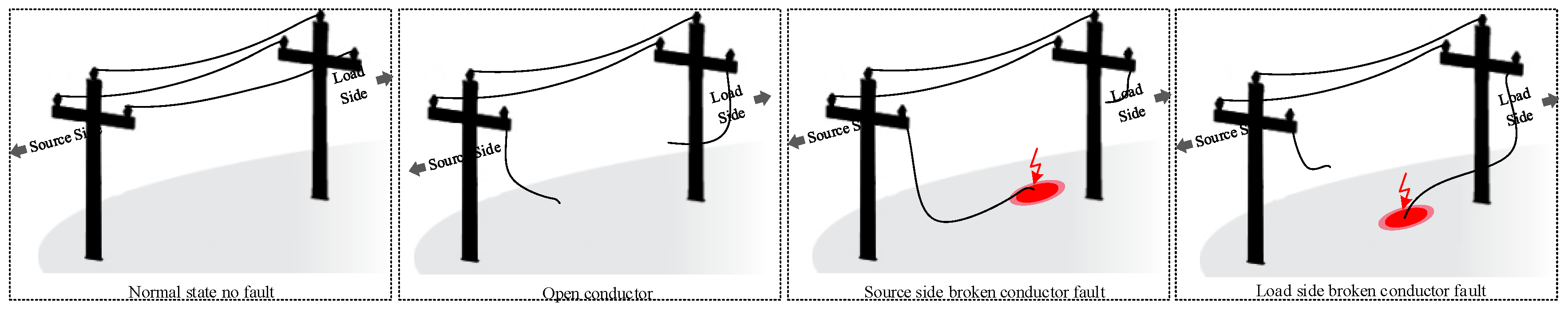
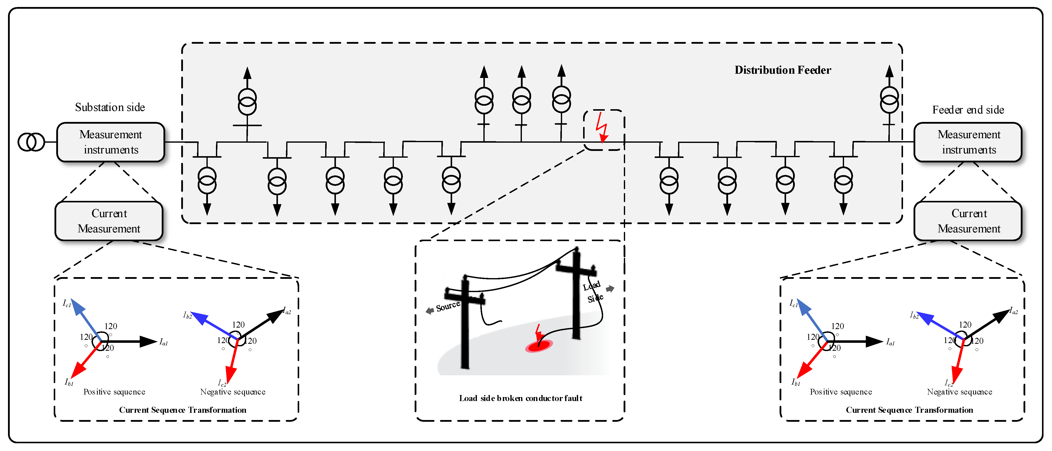
2.1. Fault Incidents

The low voltage supply network experiences abnormal voltage in two or three phases. It occurs when a broken conductor or disconnected phase causes an open-circuit fault, such as blown HV fuses in an 11 kV radially fed overhead line. This has a significant impact on the supply of electricity to customers. Such problems are often reported by customers who suffer abnormal energy supply or loss of power because of substation-based current detection techniques’ inability to identify them. Short-circuit faults can be detected using phase overcurrent and earth fault relays. Phase overcurrent and earth faults can be detected with (inverse definite minimum time) or (definite time lag) protection.
It is impossible to start an overcurrent or earth fault if an open circuit causes it. Fault impedance can be exceedingly high when a downed conductor comes into touch with highly resistant substances, such as asphalt, sand, or boulders. Back-feed earth fault current may not be detectable by overcurrent or earth fault in the distribution power transformer in the case of a downed conductor on the load side of a fault point, as shown in Figure 3.

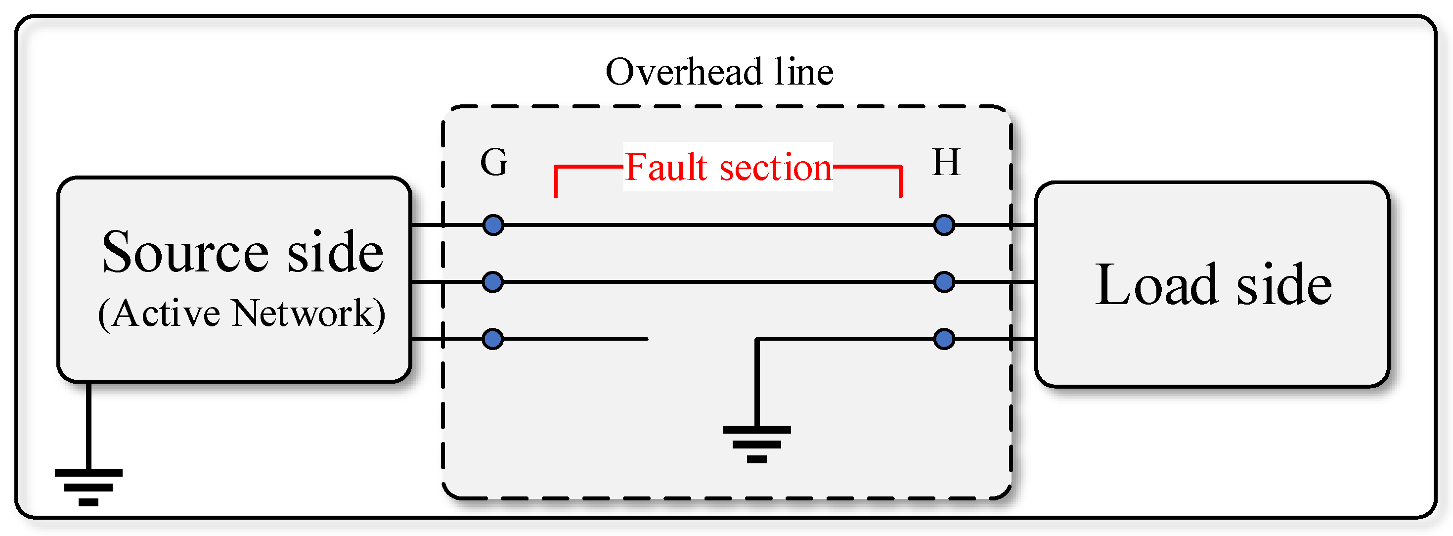
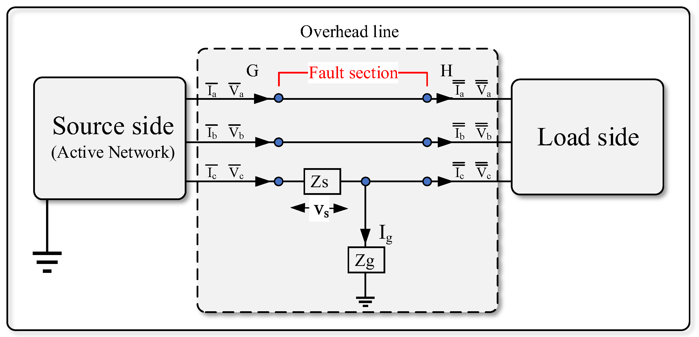
2.2. Mathematical Analysis of LSBC Fault

It is possible to represent the unbalanced power system using the phase diagram; the phase representation is by applying analytical processes. The purpose is to dismantle this unbalanced system into balanced systems, each with phases equal to the number of phases of the original unbalanced system. These balanced systems are then called symmetric compounds. Although this analytical method includes multi-phase systems, the conversation will be limited to three-phase systems. The technique is being applied to obtain identical compounds by analyzing the three unbalanced phases of the three-phase power system into three systems, each of which is three-phase and balanced. These groups of balanced compounds are: (1) Compounds of the positive relay; these consist of three phases of equal size, shifted from each other by an angle of 120, and have the same sequence of phases as the original system. (2) Compounds of the negative relay consist of three phases of equal magnitude, shifted from each other by an angle of 120, but the phase sequence here is opposite to that of the original system. (3) Compounds of the zero sequence, which consist of three phases, equal in phases, and identical in direction (that is, the value of the displacement angle between the three phases is equal to zero), so it was called the zero-sequence components [10]. Figure 4 shows the representation of symmetrical components.
As depicted in Figure 5, the LSBC concept is illustrated by a line that connects a supply-side to the load. The symmetric components transformation (SCT) can analyze LSBC faults, which is extensively applicable. Pseudo phasor algebra is applied to a sinusoidal situation using the SCT. A series impedance ZS represents the broken conductor to create a generic theory [11]. As shown in Figure 6, the shunt impedance Zg also accounts for the conductor-to-ground contact.
When the total conductor interruption occurs, the series impedance tends to infinity (i.e., ZS → ∞) while the conductor to ground solid contact leads follow Zg → 0. The LSBC fault study is performed by applying the SCT to the G and H sections, as shown in Figure 4, where: I ¯ a, I ¯ b, I ¯ c, V ¯ a, V ¯ b, V ¯ c are phase currents and phase voltages before the fault section. I ¯ ¯ a, I ¯ ¯ b, I ¯ ¯ c, V ¯ ¯ a, V ¯ ¯ b, V ¯ ¯ c are phase currents and phase voltages after the fault section.
The line currents with symmetrical components in section G are given in Equation (1).
[ I ¯ c 0 I ¯ c 1 I ¯ c 2 ] = 1 3 [ 1 1 1 1 a a 2 1 a 2 a ] [ I ¯ a I ¯ b I ¯ c ]
The subscripts 0, 1, and 2 indicate the zero, positive, and negative sequence components, respectively, where a = 1 ∠ 120°, a2 = 1 ∠ 240°. Equation (1) can be rewritten as Equation (2).
[ I ¯ c 012 ] = [ F ] 1 [ I ¯ a b c ]
In addition, section H, is rewritten as Equation (3).
[ I ¯ ¯ c 0 I ¯ ¯ c 1 I ¯ ¯ c 2 ] = 1 3 [ 1 1 1 1 a a 2 1 a 2 a ] [ I ¯ ¯ a I ¯ ¯ b I ¯ ¯ c ]
Applying Kirchhoff’s current law, the following expression in Equation (4) for the fault section can be written.
[ I ¯ ¯ a I ¯ ¯ b I ¯ ¯ c ] = [ I ¯ a I ¯ b I ¯ c I g ]
Combining (1), (3), and (4), the final formula is obtained as in Equation (5).
[ I g I g I g ] = 3 [ I ¯ c 0 I ¯ ¯ c 0 I ¯ c 1 I ¯ ¯ c 1 I ¯ c 2 I ¯ ¯ c 2 ]

2.3. Proposed Methodology

The protection engineer must understand the negative phase sequence (NPS) principle and apply the necessary settings based on different fault situations when using NPS protection on each given feeder [12]. However, the values of I2 can be sensitive to real load adjustments due to practical limitations in constructing balanced networks, where NPS protection is an excellent phase imbalance detector. Positive phase sequence (PPS) has traditionally been related to feeder loads and frequently indicates customer service quality. Overload of customer usage (or commonly asymmetrical three-phase fault) suggests that a line has too much PPS flowing over it and that the current should be terminated to maintain the benefit [13].
The day load variations in utility supply may indicate higher NPS, although this does not necessarily mean a conductor discontinuity. However, when one or more of the lines are broken, typical overcurrent/earth fault relays may fail to detect the output since the PPS does not necessarily increase. NPS protection is usually set at 30% of the overcurrent configuration. Therefore, it is safe to assume that a broken conductor will not be recognized if it is applied to feeders. When the load current is less than 10A, a broken conductor can be identified with a high degree of certainty. This phenomenon is more widespread at lower loads. For certain risks related to the failure of protection equipment, only NPS overcurrent protection can provide backup protection to solidly grounded Delta-Wye transformers [14]. Sequence components are present for a range of conditions, not only this type of faults as the open pole, load and line unbalance, breaker pole scatters, and current transformer ratio errors and saturation [15].
Thus, the NPS to PPS ratio |I2/I1| should be compared, rather than each protective factor. This helps reduce the instability in NPS numbers across the range of energy distribution to customers while also detecting an open phase discontinuity. Figure 7 depicts the proposed procedure’s flow chart. Figure 8 show the proposed methodology of this paper.

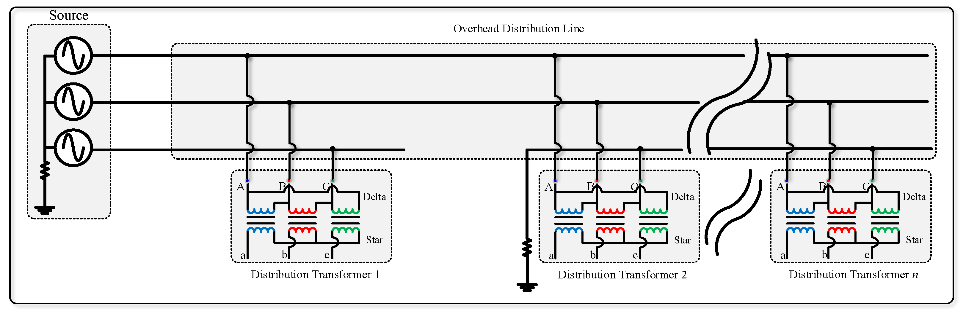
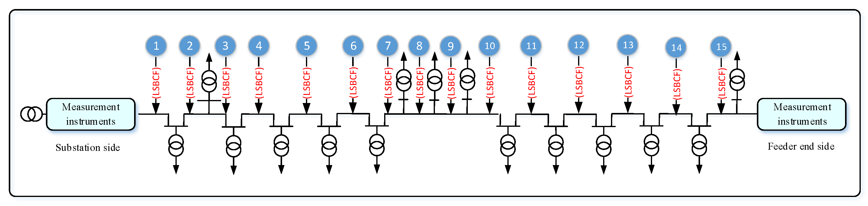
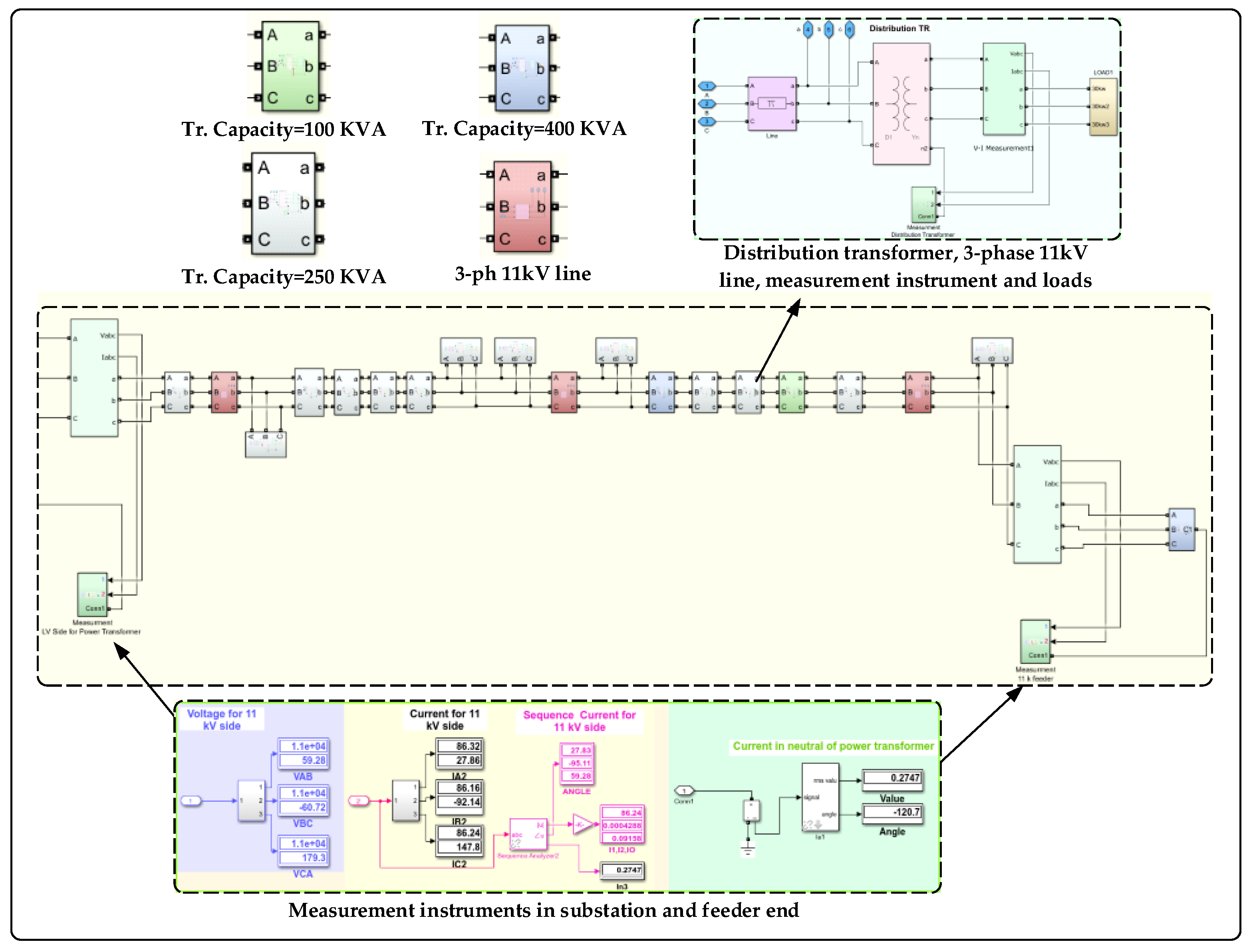
3. Case Study and Simulation Analysis

In this section, we consider the theoretical discussion. The implementation of a real network as a case study is presented. The Al-Abasia distribution substation located in the middle Euphrates region in Najaf governorate serves a large area of mixed residential, commercial, and agriculture loads and is taken as the study network. The secondary power station consists of twelve feeders, whereas the F10 feeder consists of 15 overhead transformers with a rated line to line voltage of 11 kV. The simulated circuit of the single-line diagram is presented in Figure 9. The screenshot of the MATLAB Simulink is given in Figure 10. The specification and parameters applied to this study are given in Table 1. The load of 11 distribution transformers is balanced and distributed as in Table 2.
MATLAB software and its associated Simulink toolboxes are used to test the proposed methodology. The simulation program is performed 15 times for the load side broken conductor faults in the feeder, as shown in Figure 9. The measurements were taken at the 33/11 kV substation and the end of the feeder for fifteen cases of LSBC fault. The faults start from the beginning of the feeder, and the results are given in Table 3. It is noted that the fault current in the LSBC fault phase increases from zero up to a value that becomes approximately equal to the other two phases. It causes the percentage level between the faulted and the other two phases to change between 100% and 13%.

4. Results and Discussion

4.1. Mathematical Results

In the mathematical analysis, Equation (5) was used to determine the ground current (Ig) from the sequence currents (I0) measured by the Simulink program in the substation when the fault occurs in phase C. Using Equation (6), the mathematical results were written in Table 4.
I g = 3 ( I ¯ c 0 I ¯ ¯ c 0 )
In Table 4, we noted that there is an equal absolute value of the ground current resulting from the fault in the two cases of taking measurements using the MATLAB program and the results through mathematical analysis as shown in Equation (7).
| I g | m a t h m a t i c a l = | I g | s i m u l a t i o n
The results showed that the values of the phase shift to Ig between the mathematical and MATLAB results are approximately 180° for all fifteen cases of fault sites. The same results are formed using the other measurements to sequence currents I1 and I2 by Equations (8) and (9).
I g = 3 ( I ¯ c 1 I ¯ ¯ c 1 )
I g = 3 ( I ¯ c 2 I ¯ ¯ c 2 )

4.2. Unbalance Phases Current Results

When the location of the fault is at the starting feeder, the measured values of the unfaulted lines’ currents are 86 A to 76 A. At the same time, the faulted line current in phase C is equal to zero. This is due to the presence of the LSBC fault, which is the main problem of this research paper. The protective devices are not sensitive to this type of fault due to the decrease in the values of the three-phase fault currents, unlike other types of power system faults in the Figure 1, in which the importance of the fault currents is high. When the position of the LSBC fault is far from the substation, an increase in the current values occurs in the faulty phase C until the threshold value is reached. The threshold value is the significance that determines the change in the percentage value of the unbalance currents to be 10%. The permissible percentage in the distribution networks is less than 10%. If it exceeds this value, it is considered a fault detection which the protection devices must protect the lines. In this case, 100% of the 11 kV feeder cannot be protected through unbalanced protection. Increasing the loads to more than loads of the case study in this research paper will inevitably decrease the unbalanced current table’s percentage 1 to less than 10%. To calculate the percentage ratio of the unbalance three-phase currents, we apply Equation (10)
I u n b = ( I m a x I m i n ) I m a x × 100 %
where Imax is the maximum current of three-phase currents during the LSBC faults. Imin is the minimum current of three-phase currents during the LSBC faults [16].

4.3. Neutral Fault Current Results

The results showed in Table 3 that the earth fault protection in a substation cannot detect neutral current because it was less than the permissible value 30 A in the case study (Al-Abasia substations). The current values through which the neutral protection operates vary from (30 to 150) amperes, where the earth fault current (High) is determined by Equation (11), and the earth fault current (Low) is determined by Equation (12).
I H E F = I m a x × 50 % = 300 × 50 % = 150
I L E F = I m a x × 10 % = 300 × 10 % = 30
The current value limits in Equations (10) and (11) apply when the current transformer is 300/5, the range allowed in Iraqi substations. In Table 3, the current levels in neutral varied between (7–29) A in the fifteen cases of LSBC fault, indicating that the protection devices are not responsive to the fault. Due to decreasing the loads, the longer the distance between the fault and the substation, the less current flows. The currents resulting from the fault in the neutral are the best possible state since the HIF is not taken, resulting from the conductor’s contact with more insulating materials like grass, sand, soil, and others. The problem will be increased because the fault current is not detected.

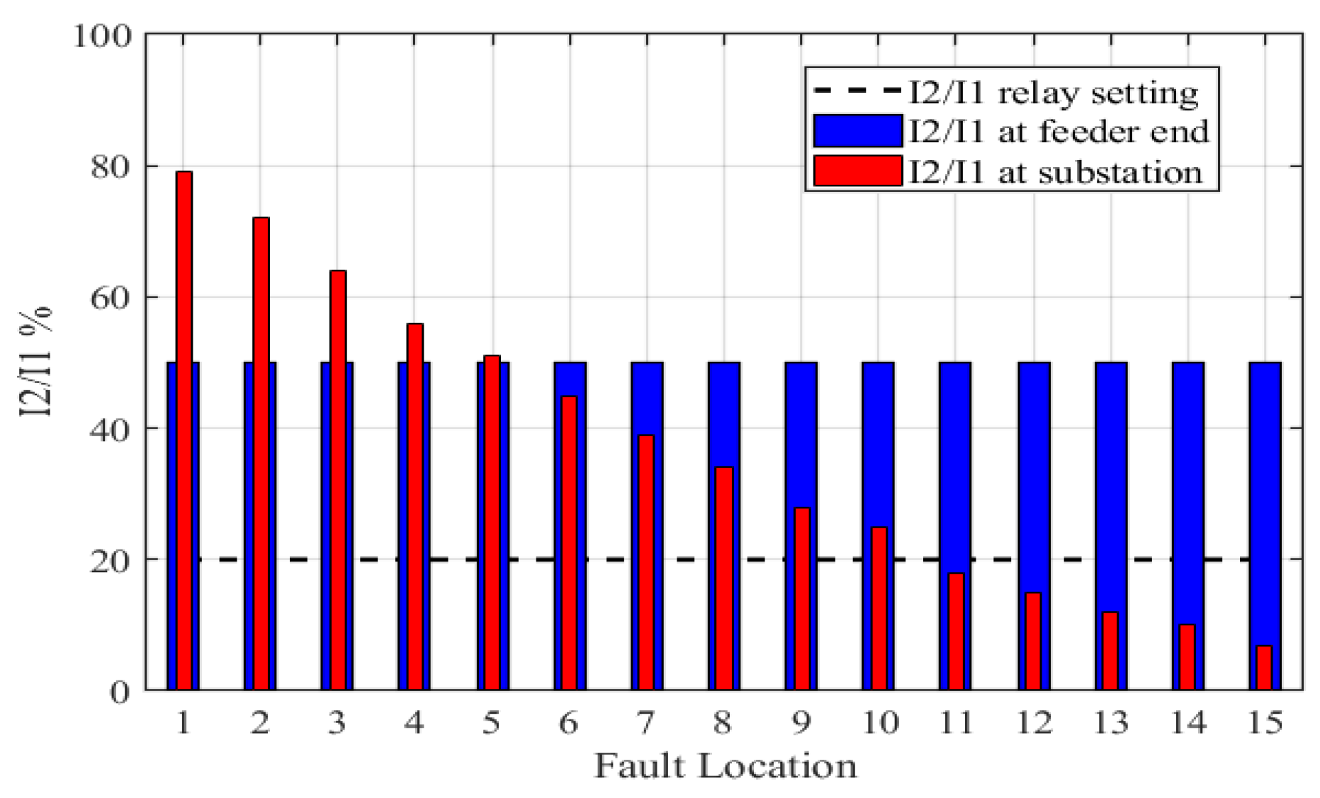
4.4. Negative to Positive Sequence Percentage Current Ratio Results

The ratio |I2/I1| was measured at two sites, first at the substation and the second at the feeder’s end. It was observed that the ratio at the substation varied between (7–79%). In comparison, it is fixed at 50% at the feeder’s end, as shown in Figure 11. The relay setting of |I2/I1| should be less than 20% [17]. In other words, the relay does not operate by less than 20%. The ratio of |I2/I1| is (7–18%) measured at the substation side for the fault site number (11–15). So, it cannot be relied upon to detect the LSBC fault, which leads us to propose another way to measure |I2/I1| at the feeder end. It is noted that the ratio of currents |I2/I1| is proven to be 50% at the end of the feeder. This ratio is for all 15 cases of faults, which is the best solution to solve the research problem. In the absence of a discontinuity, the |I2/I1| ratio is nearly constant for any variation in load demand on three phases. When a discontinuity emerges on one or more lines, the |I2/I1| ratio climbs above 20%, which is evident in a healthy line with |I2/I1| close to zero. Impedance calculations are not necessary because the positive and negative sequence impedances are identical for most residential loads, as may be concluded by looking at the ratio between I2 and I1. A comparison between the proposed method with recent literature is given in Table 5.

5. Conclusions

The electrical faults in the power system lead to a significant risk for public safety such as people, animals, crops, and forests. The LSBC fault is a specific type of fault that happens on the overhead line, which occurs on the load side since the faulted line is still energized via back-feed from the distribution transformer. This type of fault has an entirely different effect on current feeders than the traditional line-to-ground fault. For the low neutral current of LSBC fault, the earth fault protection relay does not reach the pickup value, so it cannot detect the fault. This paper presented the performance analysis based on feeder current’s NPS to PPS ratio |I2/I1|. The proposed approach is applied to a real distribution feeder in Iraq that was simulated with the MATLAB platform. The results were compared with the mathematical analysis and other related works. It was observed that the proposed |I2/I1| at the substation side protects 67% of the feeder, while the proposed |I2/I1| at the feeder end protects 100% of the feeder from LSBC fault. This paper holds several advantages compared to the previous research. Firstly, the fault is detected accurately without using distributed measurements. Secondly, the proposed method has high sensitivity on fault detection without depending on noise, power swing, transformer saturation, or harmonics. Thirdly, this method provided good analysis and found an applicable solution for the distribution utilities, which was previously missing in the literature of this field. The method can also be implemented to any other three-phase three-wire distribution feeder to get the same benefits.
For future work, we will consider analyzing other types of networks in the presence of distributed generation and evaluating the speed response of the relay. Additionally, we will study the suitable techniques for transmitting the command from the feeder end to the substation.

Author Contributions

Among those involved in the study’s conception and execution were the authors A.G.A.-B., M.K.A. and F.M.F.F., as well as its analysis and paper writing. All authors have read and agreed to the published version of the manuscript.

Funding

This research received no external funding.

Acknowledgments

We would like to express gratitude to the department of electrical engineering, university of technology—Iraq. Special thanks to the state company of the north distribution electricity, ministry of electricity, Iraq for their cooperation.

Conflicts of Interest

The authors declare no conflict of interest.

References

  1. Swetapadma, A.; Yadav, A. Fuzzy Inference System Approach for Locating Series, Shunt, and Simultaneous Series-Shunt Faults in Double Circuit Transmission Lines. Comput. Intell. Neurosci. 2015, 2015, 620360. [Google Scholar] [CrossRef] [PubMed] [Green Version]
  2. Dase, K.; Harmukh, S.; Chatterjee, A. Detecting and Locating Broken Conductor Faults on High-Voltage Lines to Prevent Autoreclosing onto Permanent Faults. In Proceedings of the 46th Annual Western Protective Relay Conference Spokane, Washington, DC, USA, 21–24 October 2019; Schweitzer Engineering Laboratories, Inc.: Washington, DC, USA, 2019. [Google Scholar]
  3. Fernandes, S.V.; Joao, D.V.; Martins, M.A.; Souza, H.G.B.; Macedo, A.F.; Martins, K.A. A Symmetrical Component Evaluation for Broken Conductor Fault Detection. In Proceedings of the 6th International Conference for Convergence in Technology (I2CT), Maharashtra, India, 2–4 April 2021; pp. 1–6. [Google Scholar]
  4. Abasi, M.; Heydarzadeh, N.; Rohani, A. Broken Conductor Fault Location in Power Transmission Lines Using GMDH Function and Single-Terminal Data Independent of Line Parameters. J. Appl. Res. Electr. Eng. 2021, 1, 22–32. [Google Scholar]
  5. Garcia-Santander, L.; Bastard, P.; Petit, M.; Gal, I.; Lopez, E.; Opazo, H. Down-conductor fault detection and location via a voltage based method for radial distribution networks. IEE Proc. Gener. Transm. Distrib. 2005, 152, 180. [Google Scholar] [CrossRef]
  6. Ostojić, M.M.; Stojanović, Z.N. An algorithm with voltage inputs for detecting conductor breaks in radial distribution networks. Int. Trans. Electr. Energ. Syst. 2021, 31, e13195. [Google Scholar]
  7. Joao, D.V.; Souza, H.G.B.; Martins, M.A.I. Broken Conductor Fault Detection using Symmetrical Components in Distribution Power Systems—An Implementation Case. In Proceedings of the IEEE PES Innovative Smart Grid Technologies Conference—Latin America (ISGT Latin America), Lima, Peru, 15–17 September 2021; pp. 1–5. [Google Scholar]
  8. Li, J.; Wang, G.; Zeng, D.; Li, H. High-impedance ground faulted line-section location method for a resonant grounding system based on the zero-sequence current’s declining periodic component. Int. J. Electr. Power Energy Syst. 2020, 119, 105910. [Google Scholar] [CrossRef]
  9. Rashad, B.A.-E.; Ibrahim, D.K.; Gilany, M.I.; El’gharably, A. Adaptive single-end transient-based scheme for detection and location of open conductor faults in HV transmission lines. Electr. Power Syst. Res. 2020, 182, 106252. [Google Scholar] [CrossRef]
  10. Salam, M.A. Fundamentals of Electrical Power Systems Analysis; Springer: Singapore, 2020; ISBN 978-981-15-3211-5. [Google Scholar]
  11. Brenna, M.; Foiadelli, F.; Sapienza, G.; Zaninelli, D. Directional ground relay failure caused by line-to-ground with load-side broken conductor fault. Euro. Trans. Electr. Power 2012, 22, 907–923. [Google Scholar] [CrossRef]
  12. Qin, L.; Zhang, L.; Wang, P.; Shi, F. Single-phase Disconnection Fault Location Method Based on Negative Sequence Current Distribution Feature. In Proceedings of the IEEE 4th International Electrical and Energy Conference (CIEEC), Wuhan, China, 28–30 May 2021; pp. 1–5. [Google Scholar]
  13. Xinyuan, L.I.; Jun, M.A.; Peng, G.A.O.; Haoran, Y.U.; Yan, L.I.N.; Haichao, L.Ü.; Zhendong, S.H.E.N. Three-Phase Power Quality Adjustment Device for Distribution Network Based on Phase Sequence Adaptive Technology. Low Volt. Appar. 2021, 61–67. [Google Scholar] [CrossRef]
  14. Prabhu, J.A.X.; Jha, J.S.; Chelluri, R.; Somidi, N. Importance Of Negative Phase Sequence Overcurrent Protection For Solidly Grounded Delta-Wye Transformer. In Proceedings of the 3rd International Conference on Recent Developments in Control, Automation & Power Engineering (RDCAPE), Noida, India, 10–11 October 2019; pp. 12–16. [Google Scholar]
  15. Kasztenny, B.; Mynam, M.V.; Fischer, N. Sequence Component Applications in Protective Relays–Advantages, Limitations, and Solutions. In Proceedings of the 72nd Annual Conference for Protective Relay Engineers (CPRE), College Station, TX, USA, 25–28 March 2019; pp. 1–23. [Google Scholar]
  16. Pan, J.; Liu, J.; Chen, X.; Zhong, K. Three-Phase Unbalanced Load Control Based on Load–Electricity Transfer Index. In Proceedings of the International Conference on Power Engineering, Energy Reports 7, Sanya, China, 19–21 November 2021; pp. 312–318. [Google Scholar]
  17. Rungseevijitprapa, W.; Pongthavornsawad, A. A Noval Detection System for Broken Distribution Conductor on Radial Scheme. In Proceedings of the 21st International Conference on Electricity Distribution Frankfurt, Frankfurt, Germany, 6–9 June 2011; p. 644. [Google Scholar]
Figure 1. Classification of power system faults.
Electronics 11 00836 g001
Figure 2. The conditions of normal state and broken conductor faults.
Electronics 11 00836 g002
Figure 3. The back-feed from distribution transformers in load side broken conductor fault.
Electronics 11 00836 g003
Figure 4. Representation of symmetrical components.
Electronics 11 00836 g004
Figure 5. Description of a fault section.
Electronics 11 00836 g005
Figure 6. Description of a fault section (including the shunt impedance Zg).
Electronics 11 00836 g006
Figure 7. The flow chart of the proposed method.
Electronics 11 00836 g007
Figure 8. The proposed methodology.
Electronics 11 00836 g008
Figure 9. Implement the LSBC fault on the distribution feeder.
Electronics 11 00836 g009
Figure 10. Simulation of the real feeder.
Electronics 11 00836 g010
Figure 11. Negative to positive sequence percentage current ratio.
Electronics 11 00836 g011
Table 1. The parameters of the study network.
ParametersValue
Rated power of power transformers(2 × 31.5) MVA
The voltage level of the power transformer(33/11) kV
Rated frequency50 Hz
The voltage level of distribution transformers(11/0.4) kV
Vector group of distribution transformersDyn11
Rated power of distribution transformers(630, 400, 250, and 100) kVA
Type of conductorACSR 120/20 mm2
Resistance of conductor0.246 ohm/km
Reactance of conductor0.2899 ohm/km
Type of distribution feeder3-phase 3-wire
Length of 11 kV feeder4 km
Table 2. Distribution of the load for the case study.
Transformer Capacity (kVA)Connected Load (kW)Bus No.
1003013
2509011,12,14,15
961,2,3,4,5,6,7,8,9
40015010
Table 3. The measurements at substation and feeder end.
Fault LocationSubstation SideFeeder End Side
Ia (A)Ib (A)Ic (A)Iunb%In (A)I1I2I2: I1%I1I2I2: I1%
No fault86 ∠ 2886 ∠ 2886 ∠ 280086 ∠ 28008.2 ∠ 2700
176 ∠ 4776 ∠ −111010029 ∠ 14848 ∠ 2838 ∠ 88795.5 ∠ 272.7 ∠ 8750
277 ∠ 4676 ∠ −1105 ∠ 1499327 ∠ 14850 ∠ 2836 ∠ 88725.5 ∠ 272.7 ∠ 8750
377 ∠ 4477 ∠ −10911 ∠ 1498525 ∠ 14853 ∠ 2834 ∠ 88645.5 ∠ 272.7 ∠ 8750
477 ∠ 4377 ∠ −10716 ∠ 1497923 ∠ 14855 ∠ 2831 ∠ 88565.5 ∠ 272.7 ∠ 8750
578 ∠ 4278 ∠ −10621 ∠1497322 ∠ 14857 ∠ 2829 ∠ 88515.5 ∠ 272.7 ∠ 8750
678 ∠ 4178 ∠ −10527 ∠ 1496520 ∠ 14860 ∠ 2827 ∠ 87455.5 ∠ 272.7 ∠ 8750
779 ∠ 3979 ∠ −10432 ∠ 1485918 ∠ 14862 ∠ 2824 ∠ 87395.5 ∠ 272.7 ∠ 8750
880 ∠ 3879 ∠ −10237 ∠ 1485316 ∠ 14864 ∠ 2822 ∠ 87345.5 ∠ 272.7 ∠ 8750
980 ∠ 3780 ∠ −10143 ∠ 1484615 ∠ 14867 ∠ 2819 ∠ 87285.5 ∠ 272.7 ∠ 8750
1081 ∠ 3680 ∠ −10048 ∠ 1484113 ∠ 14869 ∠ 2817 ∠ 87255.5 ∠ 272.7 ∠ 8750
1182 ∠ 3482 ∠ −9856 ∠1483210 ∠ 14873 ∠ 2813 ∠ 87185.5 ∠ 272.7 ∠ 8750
1283 ∠ 3382 ∠ −9761 ∠ 148278 ∠ 14875 ∠ 2811 ∠ 87155.5 ∠ 272.7 ∠ 8750
1383 ∠ 3283 ∠ −9666 ∠ 148207 ∠ 14877 ∠ 289 ∠ 87125.5 ∠ 272.7 ∠ 8750
1483 ∠ 3183 ∠ −9568 ∠ 148186 ∠ 14878 ∠ 288 ∠ 87105.5 ∠ 272.7 ∠ 8750
1584 ∠ 3084 ∠ −9573 ∠ 148134 ∠ 14880 ∠ 286 ∠ 8775.5 ∠ 272.7 ∠ 8750
Table 4. Comparison between simulation and mathematical result.
Fault LocationSource SideLoad SideSimulationMathematical
I ¯ c1 (A) I ¯ c2 (A) I ¯ c0 (A) I ¯ ¯ c 1   ( A ) I ¯ ¯ c 2   ( A ) I ¯ ¯ c 0   ( A ) Ig (A)Ig (A)
147.91 ∠ 27.8638.33 ∠ 87.809.584 ∠ −31.8757.49 ∠ 27.8828.74 ∠ 87.740.030 ∠ 59.4628.75 ∠ 148.128.75 ∠ −32
244.95 ∠ 27.8235.97 ∠ 87.768.984 ∠ −31.9553.94 ∠ 27.8326.98 ∠ 87.720.025 ∠ 59.1926.95 ∠ 148.126.95 ∠ −32
342.00 ∠ 27.8033.61 ∠ 87.748.394 ∠ −31.9850.40 ∠ 27.8125.21 ∠ 87.700.024 ∠ 59.1925.18 ∠ 148.025.18 ∠ −32
439.05 ∠ 27.7731.25 ∠ 87.717.802 ∠ −32.0346.85 ∠ 27.7723.44 ∠ 87.680.022 ∠ 59.0523.41 ∠ 148.023.41 ∠ −32
536.10 ∠ 27.7428.89 ∠ 87.697.210 ∠ −32.0843.31 ∠ 27.7421.68 ∠ 87.670.019 ∠ 58.9321.63 ∠ 147.921.63 ∠ −32
633.14 ∠ 27.7126.53 ∠ 87.676.619 ∠ −32.1239.76 ∠ 27.7219.91 ∠ 87.650.016 ∠ 58.8219.86 ∠ 147.919.86 ∠ −32
730.19 ∠ 27.6924.16 ∠ 87.666.029 ∠ −32.1536.22 ∠ 27.7018.14 ∠ 87.640.014 ∠ 58.7618.09 ∠ 147.818.09 ∠ −32
827.24 ∠ 27.6821.80 ∠ 87.655.441 ∠ −32.1632.68 ∠ 27.6816.36 ∠ 87.630.010 ∠ 58.7516.32 ∠ 147.816.32 ∠ −32
924.29 ∠ 27.6619.44 ∠ 87.634.852 ∠ −32.1929.15 ∠ 27.6614.59 ∠ 87.620.013 ∠ 58.7114.56 ∠ 147.814.56 ∠ −32
1021.34 ∠ 27.6417.08 ∠ 87.604.263 ∠ −32.2225.61 ∠ 27.6412.82 ∠87.600.011 ∠ 58.7012.79 ∠ 147.812.79 ∠ −32
1116.77 ∠ 27.7413.42 ∠ 87.713.350 ∠ −32.1120.12 ∠ 27.7410.07 ∠ 87.710.011 ∠ 58.6810.05 ∠ 147.910.05 ∠ −32
1213.82 ∠ 27.7411.06 ∠ 87.702.761 ∠ −32.1016.58 ∠ 27.738.295 ∠ 87.700.010 ∠ 58.668.284 ∠ 147.98.284 ∠ −32
1311.05 ∠ 27.728.841 ∠ 87.672.208 ∠ −32.1113.26 ∠ 27.706.633 ∠ 87.680.009 ∠ 58.656.625 ∠ 147.96.625 ∠ −32
1410.11 ∠ 27.658.091 ∠ 87.612.021 ∠ −32.1712.13 ∠ 27.646.070 ∠ 87.620.009 ∠ 58.646.063 ∠ 147.86.063 ∠ −32
157.343 ∠ 27.605.876 ∠ 87.551.468 ∠ −32.178.812 ∠ 27.584.407 ∠ 87.570.009 ∠ 58.634.404 ∠ 147.84.404 ∠ −32
Table 5. Comparison between the proposed method with recent literature.
The Proposed MethodThe Available Literature Methods
  • One measurement unit is needed at the feeder end.
  • The relays are needed in each bus of the grid [3].
  • Requires a voltage sensor to be placed at each end of the MV branch [5].
  • Fault indicating devices are needed [8].
  • Detection does not depend on transformer connection (delta-star) or (star-delta).
  • Some drawbacks are mainly related to the delta transforms placed [3].
  • No need for collecting system historical data.
  • Need for collecting historical system data [4].
  • Detection the faults in ungrounded and overhead lines.
  • Detecting the faults in ungrounded cables [6].
  • Detect the faults when using single-phase and three-phase transformers.
  • Mainly detects the fault in a scenario with single-phase transformers [7].
  • No complicated communication is needed.
  • Feeder terminal units that are needed to install along the feeder with advanced communication links lead to additional hardware and software complexity [8].
  • Applicable with the traditional overcurrent and earth fault protection.
  • Not applicable with the traditional protections [3,4,5,6,8].
Publisher’s Note: MDPI stays neutral with regard to jurisdictional claims in published maps and institutional affiliations.

