Article

A Dual-Armed Robotic Puncture System: Design, Implementation and Preliminary Tests

State Key Laboratory of Robotics and System, Harbin Institute of Technology, Harbin 150001, China
*
Author to whom correspondence should be addressed.
Electronics 2022, 11(5), 740; https://doi.org/10.3390/electronics11050740
Submission received: 7 December 2021 / Revised: 15 February 2022 / Accepted: 22 February 2022 / Published: 28 February 2022
(This article belongs to the Special Issue Physical Diagnosis and Rehabilitation Technologies)

Abstract

:
Traditional renal puncture surgery requires manual operation, which has a poor puncture effect, low surgical success rate, and high incidence of postoperative complications. Robot-assisted puncture surgery can effectively improve the accuracy of punctures, improve the success rate of surgery, and reduce the occurrence of postoperative complications. This paper provides a dual-armed robotic puncture scheme to assist surgeons. The system is divided into an ultrasound scanning arm and a puncture arm. Both robotic arms with a compliant positioning function and master–slave control function are designed, respectively, and the control system is achieved. The puncture arm’s position and posture are decoupled by the wrist RCM mechanism and the arm decoupling mechanism. According to the independent joint control principle, the compliant positioning function is realized based on the single-joint human–computer interactive admittance control. The simulation and tests verify its functions and performance. The differential motion incremental master–slave mapping strategy is used to realize the master–slave control function. The error feedback link is introduced to solve the cumulative error problem in the master–slave control. The dual-armed robotic puncture system prototype is established and animal tests verify the effectiveness.

Graphical Abstract

1. Introduction

A kidney biopsy is currently the main method that can achieve a clear diagnosis of diffuse renal diseases [1]. At present, there are two methods to achieve needle biopsy, namely the freehand puncture and ultrasound guided puncture. Freehand biopsy in the traditional way is labor-intensive. With the progression of the operation, the operation accuracy declines continuously. In addition, the inevitable tremor during the puncture operation greatly affects the puncture effect, leading to a low success rate of punctures. The operation is accompanied by mild or severe complications, which seriously endangers the health of the patient [2]. Thus, it is necessary to develop a robot-assisted percutaneous puncture system, to enable doctors to perform renal puncture operations more accurately and efficiently and further reduce the pain of the patient during the operation.
Due to the strong clinical demand for puncture surgery, many institutions have carried out related research. Stoianovici et al. [3] developed a spinal and renal puncture surgery robot named “Acubot”, and a pneumatically driven puncture surgery robot that can replace the puncture mechanism [4]. Mitchell et al. [5] developed a retinal surgery robot. Üneri et al. [6] and He et al. [7] improved its human–computer interaction performance and obtained EyeRoBot2 and EyeRoBot2.1, respectively. The navigation of puncture surgery robots mainly uses external image guidance [8], including CT [9,10], MRI [11,12], and ultrasound [13,14,15,16], among which ultrasound image guidance is widely used. Boctor et al. [13] developed an ultrasound-guided hepatic puncture surgical robot. Hong et al. [14] developed an ultrasound-guided puncture robot, UMI, which can adjust the puncture needle path through real-time ultrasound navigation. Kettenbach et al. [15] designed a tissue biopsy puncture robot, B-Robot-I, based on ultrasound navigation. Bassan et al. [16] developed a three-dimensional ultrasound navigation robot for prostate tumor puncture surgery. Although the puncture robot has been studied for years, it lacks practicality. A very important reason is that the existing system is unable to meet the safety requirement of surgery and satisfy the usage habits of surgeons.
The clinical demand for robot-assisted surgery has also promoted the research of surgical robot systems. Computer Motion has developed the ZEUS surgical robot system [17,18]. Intuitive Surgical has developed the master–slave teleoperation da Vinci surgical robot system [19]; after system improvement, the da Vinci Xi [20] and da Vinci SP systems have been developed, whose effectiveness is widely accepted. Hannaford et al. [21] developed the open-source surgical system Raven II. Konietschke et al. [22] and Hagn et al. [23] developed the DLR MiroSurge lightweight surgical robot system. Although most robot-assisted surgery robots interpret the meaning of minimally invasive, commercial systems pay more attention to the preoperative docking effect and the master–slave operation during the operation. In a sense, whether docking and master–slave operation are easy to use determines whether the puncture robot can be applied to clinical applications.
At present, there are few clinical applications on the robotic system for renal puncture. The main contributions of this paper are as follows. (1) A dual-armed robotic system prototype with master–slave control and a dragging docking function for percutaneous puncture is reported to assist the traditional renal puncture. The system is divided into an ultrasound scanning arm and a puncture arm. The puncture arm is designed with a position and posture decoupling function to guarantee the puncture safety. (2) An interaction force control method is proposed for the positioning arm during the docking operation. (3) The robotic system for renal puncture is verified by animal tests.
This paper is organized as follows. Section 2 describes the mechanical design and the kinematic modeling of the dual-armed robotic system. Section 3 presents the robot control system and control strategy. Section 4 describes the simulation analysis of the control strategy and the animal tests. In the last part, the designed dual-armed robotic system for renal puncture is summarized and prospected.

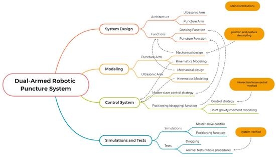
2. System Design and Modeling

The system architecture of the dual-armed robotic system is shown in Figure 1. The dual-armed robotic system is divided into an ultrasonic (US) scanning arm and a puncture arm. The ultrasonic robotic arm is designed to provide image guidance for the operation. The puncture arm with the position and posture decoupling function performs the puncture operation, with the consideration of the puncture safety. During the docking operation, the two arms are positioned on the patient by dragging. During the surgery, the surgeons can use one master operator to control the US arm moving on patients for scanning, while using another master operator to control the puncture arm to adjust the posture of the needle.

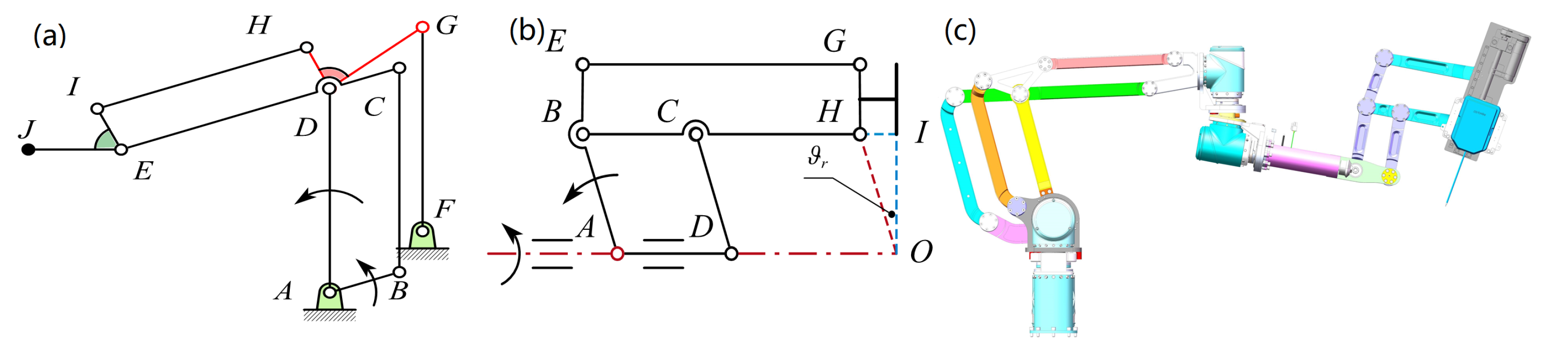
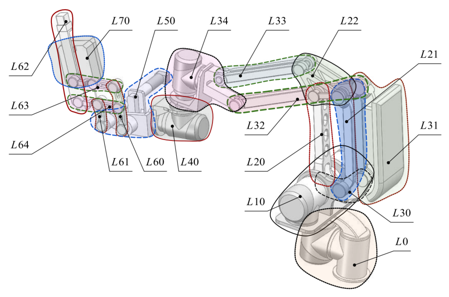
2.1. Mechanical Design and Kinematic Modeling of Puncture Arm

2.1.1. Mechanical Design of Puncture Arm

During the dragging process, the robotic arm is easily restricted by the flexible working space and joint singularities of the robotic arm. In order to make the dragging process simple and easy, the puncture arm adopts a position and posture decoupling mechanical structure.
The puncture arm is divided into the arm and wrist. The arm and wrist determine the position and posture of the puncture needle, respectively. Regardless of the rotation of the puncture needle, the puncture arm only needs five degrees of freedom to complete the positioning of the puncture needle. However, redundant degrees of freedom are required for doctors to avoid some surgical positions. Thus, we provide a redundant degree of freedom at the end of the arm. The wrist provides two posture angles for the puncture needle. The arm is decoupled from the wrist, and the arm is responsible for giving the position of the puncture point and the redundant posture angle. The arm structure is shown in Figure 2a. The wrist adopts a two-dimensional Remote Center of Motion (RCM) mechanism (see Aksungur [24]), and its distal virtual point is the required puncture point. The range of motion of the two-dimensional RCM mechanism can be calculated by the required puncture angle. The arm is actually a decoupling mechanism. The RCM mechanism used in this paper is shown in Figure 2b. The final mechanical structure of the puncture arm is shown in Figure 2c.

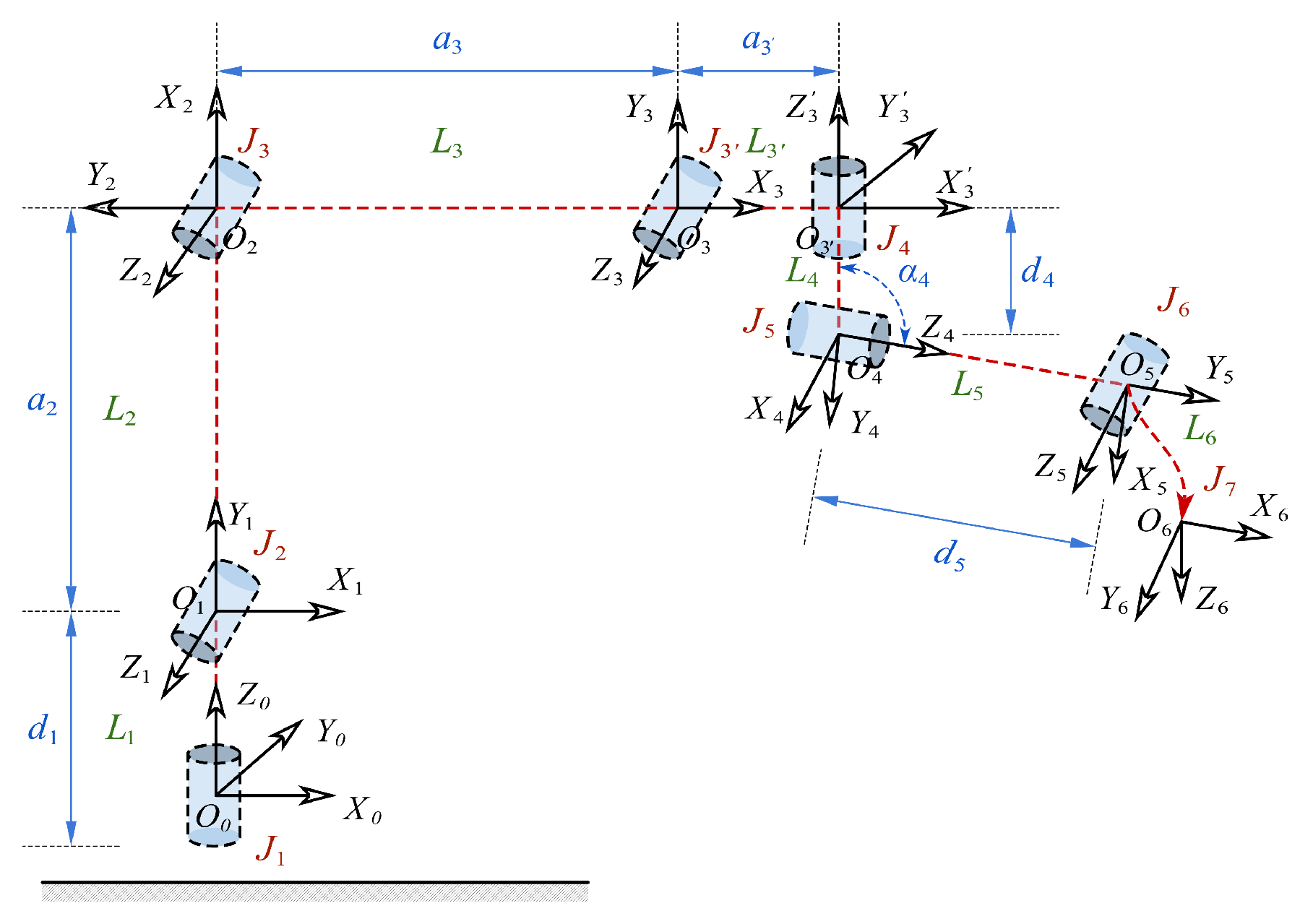
2.1.2. Kinematic Modeling of the Puncture Arm

Due to the existence of the arm decoupling mechanism, a passive joint is introduced. Thus, the puncture arm actually contains seven joints with kinematic meaning but has only six degrees of freedom. The D-H coordinate system is established for the mentioned seven joints, as shown in Figure 3. Among them, joint J 3 is the redundant passive degree of freedom caused by position and posture decoupling and joint 7 represents the RCM point at the end. The positive kinematics equation contains seven joint variables and defines six generalized variables q 1 q 6 corresponding to motors. The D-H parameters are expressed by generalized variables, as shown in Table 1.

2.2. Mechanical Design and Kinematic Modeling of Scanning Arm

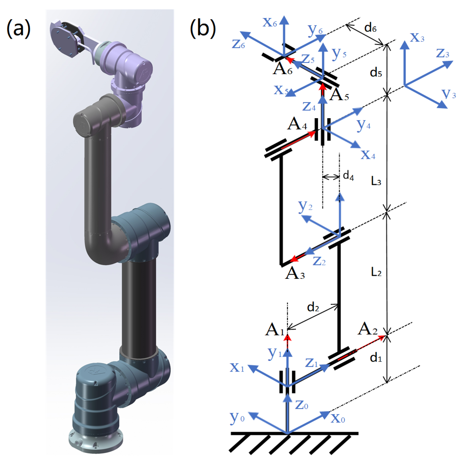
2.2.1. Mechanical Design of Scanning Arm

The function of the scanning arm is to provide image guidance for the puncture operation. High-quality images are conducive to the improvement of the accuracy of the operation. Thus, it is necessary to have different operation modes for doctors to choose. However, it has no special requirements for the structure design, so the choice of the scanning arm is a common 6-degree-of-freedom universal robotic arm with an ultrasonic probe, as shown in Figure 4a. These six joints are all rotary joints, and the axes of joints 2, 3, and 4 are parallel to each other, which has good working space and operation dexterity.

2.2.2. Kinematic Modeling of Scanning Arm

The six joints of the scanning arm are all designed as rotating joints. The linkage parameters and D-H coordinate system of the scanning arm are shown in Figure 4b. The positive kinematics equation contains six joint variables, and the D-H parameters expressed by joint variables are shown in Table 2.

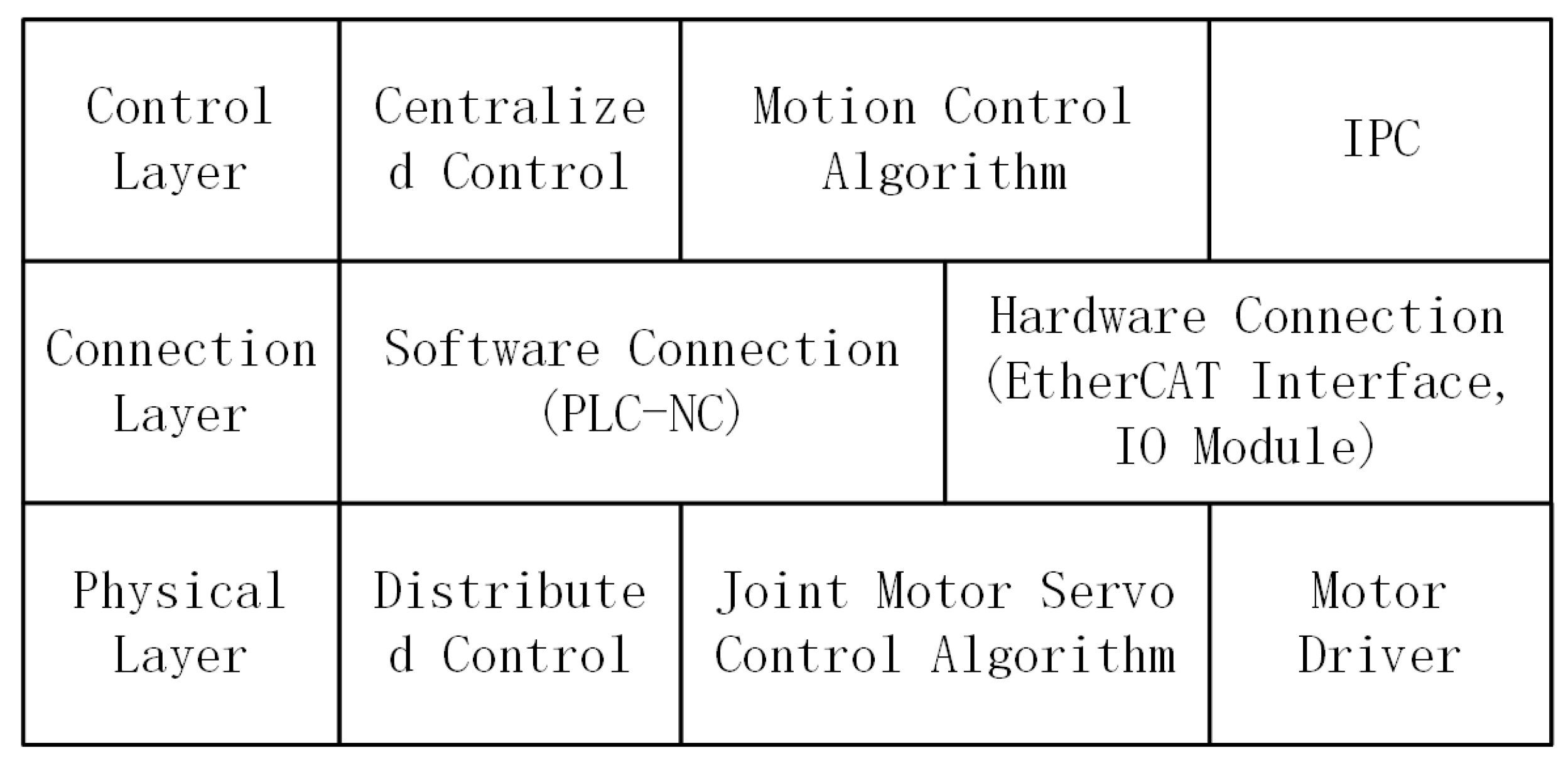
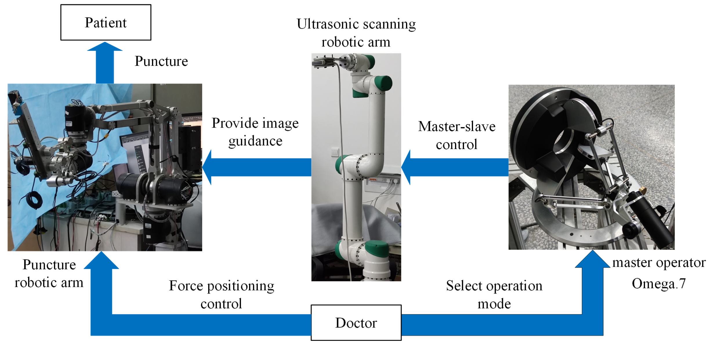
3. The Implementation of the Control System

The dual-armed puncture system adopts a centralized–distributed architecture, as shown in Figure 5. The upper-level control algorithm is centralized to the industrial computer to realize, and the joint motor servo control algorithm is distributed to the independent driver on the bus to realize. The upper layer and the bottom layer are linked together through the connection layer, including the software interface that connects the PLC and Numerical Control (NC), and the hardware interface including an EtherCAT coupler and general IO module.

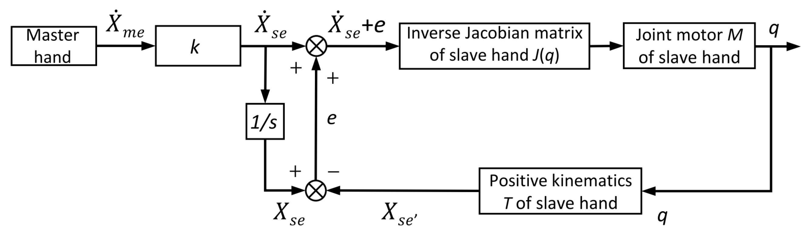
3.1. Master–Slave Control Strategy

This paper adopts the master–slave mapping strategy of differential motion increment based on the inverse Jacobian matrix, and the master hand uses Omega7 of the Force Dimension company. The master–slave mapping strategy uses the differential displacement increment in a small time period to replace the instantaneous speed, and the linear solution can be obtained only by using the Jacobian matrix, which is convenient for programming and calculation.
The linear solution equation for the discretized scanning arm inverse kinematics problem can be described as:
Δ q = J ( q ) 1 Δ x e Δ q = q ˙ Δ t Δ x e = p e ˙ ϕ e ˙ T Δ t
where Δ q is the differential increment of the joint space, Δ x e is the differential motion increment of the position and Euler angle of the end of the scanning arm in Cartesian space, and the time interval is Δ t .
In addition, this method of linearly equivalent generalized velocity to differential motion increment has the following errors:
e = Δ x e J ( q ) Δ q .
The error e is a high-order error and can be ignored in the calculation. However, this kind of small error will continue to accumulate, leading to a large master–slave following error of the end effector. Thus, the differential motion incremental master–slave mapping algorithm based on the inverse Jacobian matrix needs to introduce a feedback link, to eliminate the accumulation of errors.
The master–slave real-time control algorithm in this paper is as follows. Collecting the differential motion increment of the position and posture of the master hand Omega7, the working space of the master hand and scanning arm are combined to determine the master–slave space mapping function. Then, the expected differential motion increment of the end effector’s position and posture of the scanning arm is obtained through mapping. After this, the inverse Jacobian matrix is used to calculate the expected differential angle increment of each joint of the scanning arm, and finally the expected angle of each joint is calculated. Lastly, the expected angle of each joint is used as the input of the underlying control algorithm of the joint motor module.
The master–slave control strategy based on the differential motion increment of the inverse Jacobian matrix with error compensation is shown in Figure 6. The control process uses speed as a variable, but in the actual algorithm, the differential motion increment is used for programming calculations instead of speed. This kind of master–slave control algorithm reduces the calculation time, and the design of the error feedback link also improves the accuracy of the master–slave control algorithm.

3.2. Control Strategy for Positioning during Docking

The positioning control strategy can realize the preoperative positioning of the arm during docking operation. The surgeons can drag the arm directly to determine the position and posture of the puncture operation. In this situation, the arm needs to provide a compliant operating experience. According to the characteristics of the puncture arm and the architecture of the control system, this paper proposes a joint-space admittance control strategy to achieve compliant positioning operation, which is based on the admittance control strategy for independent joint control. This method actually superimposes the admittance control to an independent joint control strategy, to obtain the compliant control effect. During the drag process of the puncture arm, it will be affected by the gravity moment and the nonlinear coupling moment. In the drag application, the acceleration is small enough, and the nonlinear coupling moment can generally be ignored. However, the gravity moment cannot be ignored. In this paper, joint torque sensors are installed for each drive joint for gravity moment identification.

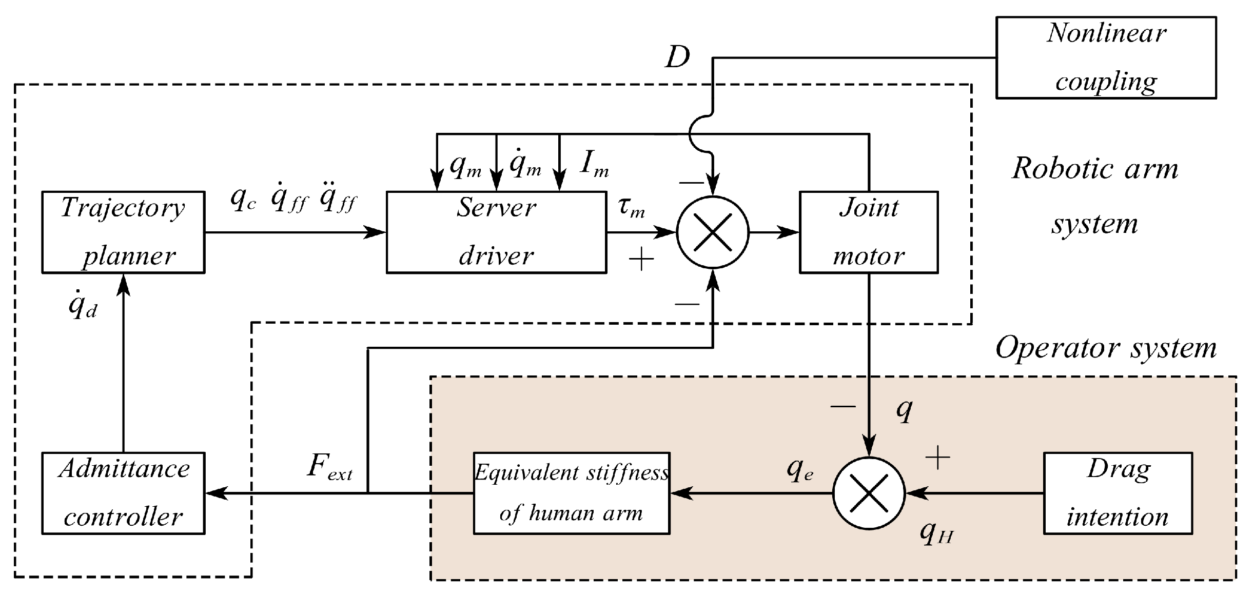
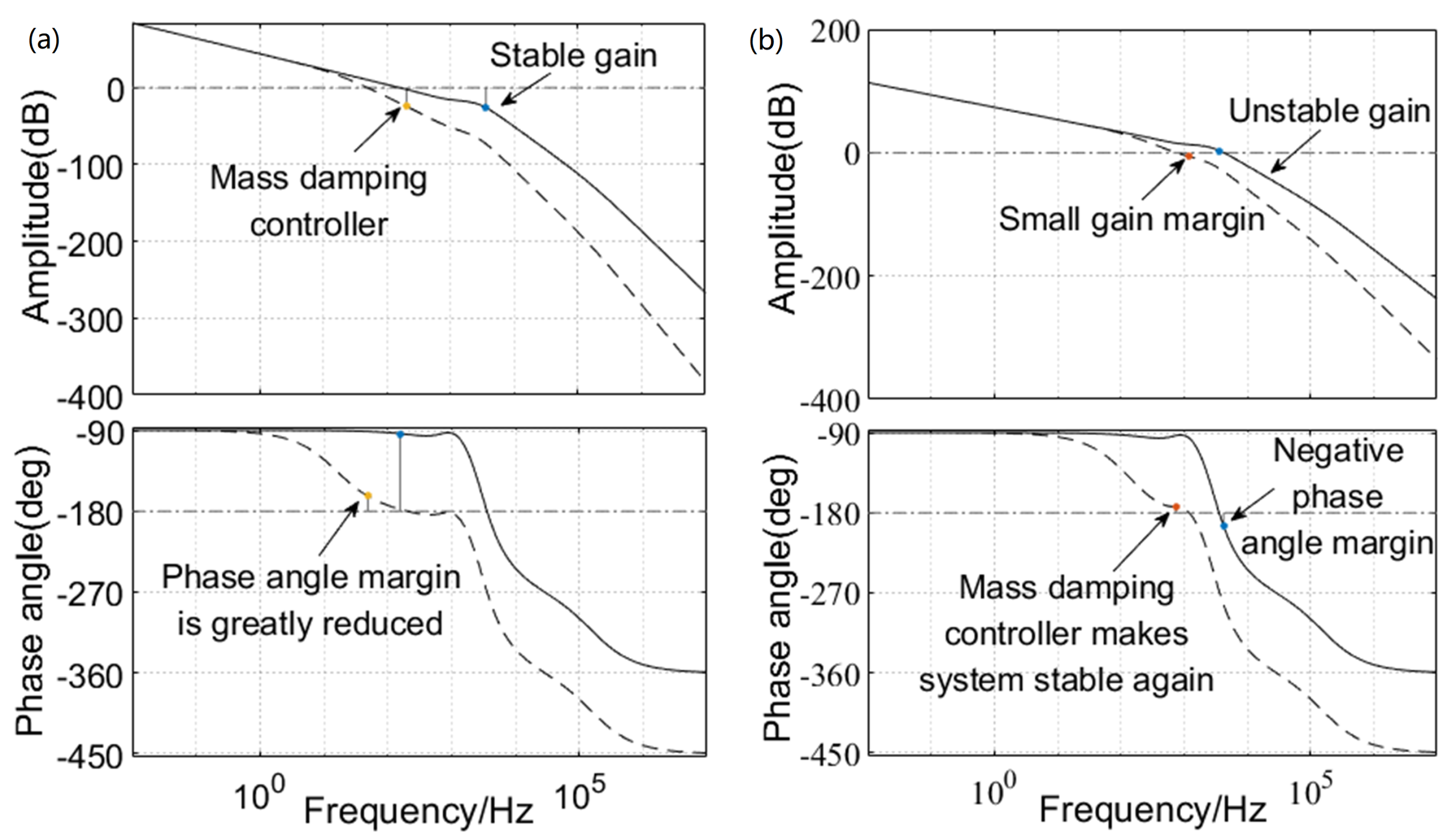
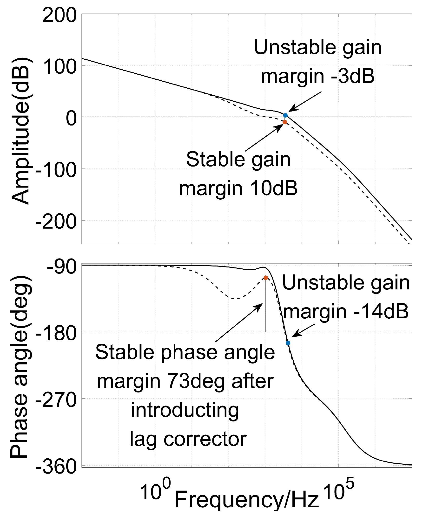
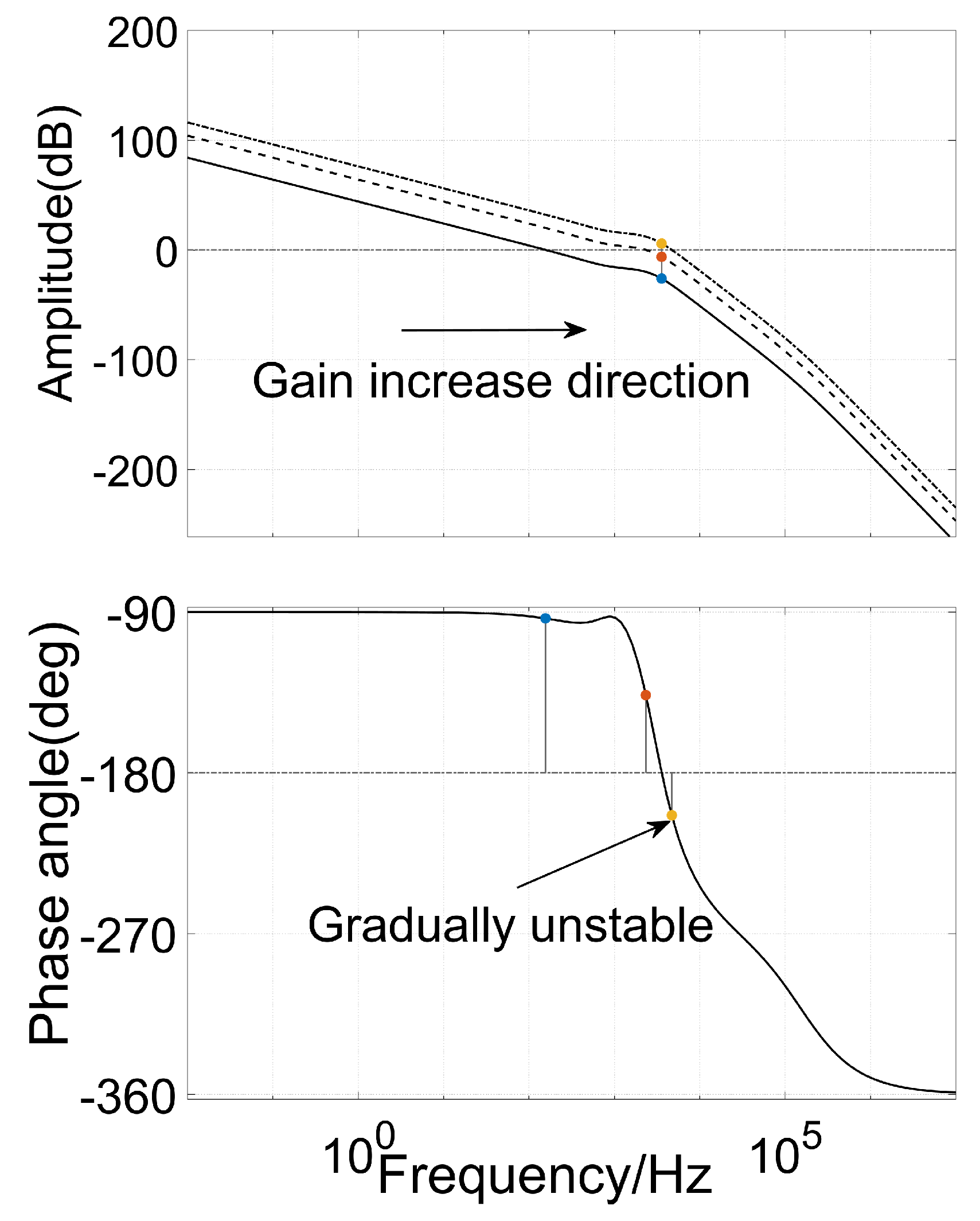
3.2.1. Design of Mass Damping Controller

The principle of the human–computer interaction admittance control is shown in Figure 7. The interaction force acts on each joint, so there is no need for the transformation of the transposed Jacobian matrix. In the actual design of the controller, it can be considered that the output of the admittance controller is a speed command. The admittance of the controller [25] is defined as
Y = q d ˙ F e x t .
In the controller, admittance Y only represents the conversion from drag force F e x t to control speed q d ˙ .
The most ideal equal admittance control system of the robotic arm joint is a mass damping system. The process of dragging a robotic arm joint equals dragging a mass. The mass and damping of the mass and the equal stiffness of the human arm determine the dragging experience and effect. The equivalent control block diagram of the human–computer interaction system considering the operator is shown in Figure 8.
A simple approximation is made here. The operating system (the human) is equivalent to a fixed stiffness K H . Thus, the equivalent model of the entire system is linearized as a second-order system, which can be described as
Y = K H M s 2 + C s + K H ,
when the admittance controller selects the mass damping system, expressed as
Y = q d ˙ F e x t = 1 M s + C .
The system represented by Equation (4) can be obtained. The second-order system is the simplest form of the control system, and the desired effect can be easily achieved by adjusting the parameters. However, this situation is not in line with reality, so the purpose of the admittance controller is to choose a suitable controller architecture, to make the system as close to the ideal form as possible.

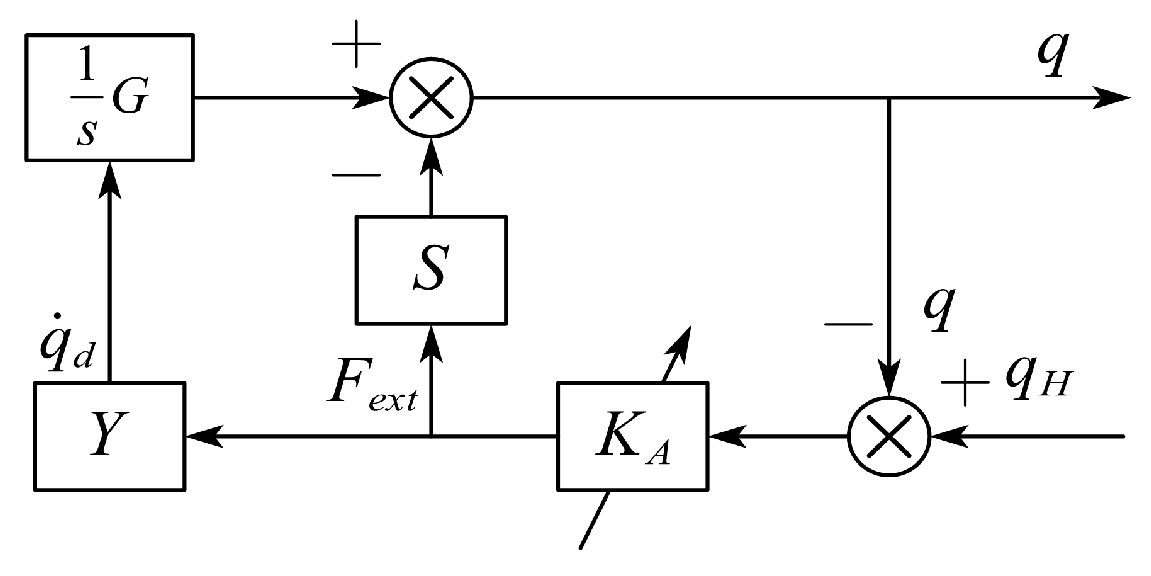
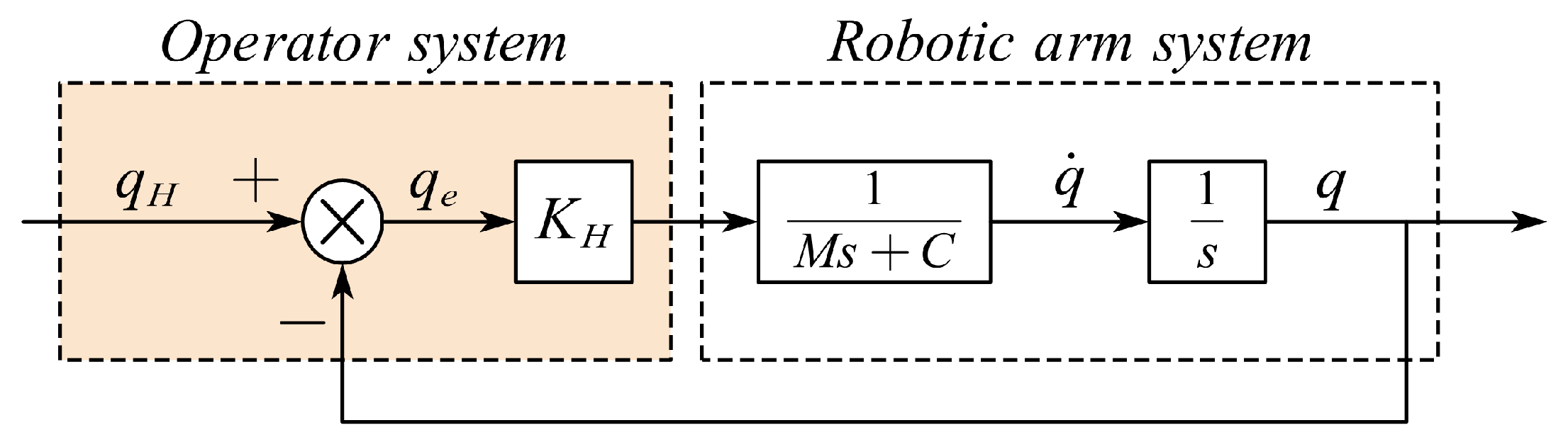
3.2.2. Design of Human–Computer Interactive Admittance Controller

The human–computer interaction system shown in Figure 7 is actually nonlinear. The nonlinearity of the operator’s arm system [26] is difficult to describe with an accurate mathematical model, but a reasonable approximation can be made, assuming that the operator’s arm is a variable stiffness impedance system, which can be linearized and approximated. The result after the linear approximation is shown in Figure 9. In the linearized model, the factors affecting the human–computer interaction performance mainly include three aspects: the stiffness of the human arm K A , the designed admittance controller Y, and the servo drive models G and S. The control of the linearized model is actually a series correction of the system. In fact, when the admittance controller adopts the lag correction strategy, the best effect is achieved. The typical lag correction strategy is as follows:
Y = q d ˙ F e x t = K Y T 1 s + 1 T 2 s + 1 .
After adding the operator system and admittance controller to form a new system, system stability should be reconsidered. The stability of the system is mainly affected by the stiffness K A of the human arm and the admittance controller Y. The arm stiffness K A and the gain K Y in the admittance controller can be equal to the coefficient K for consideration.

3.3. Joint Gravity Moment Modeling and Parameter Identification

Since the puncture arm has seven degrees of freedom, there are seven gravity moment parameters for seven generalized variables q. As shown in Figure 10, all the link combinations in kinematics are given, where L 1 x is the length of links for axis 1, L 2 x for axis 2 and so on. Obviously, gravity moments g 1 and g 4 for q 1 and q 4 are zero. As the position and posture are decoupled, the motions of joint 2 and joint 3 will not change the posture of joints 5, 6, and 7. Thus, we can make the following simplification:
g 1 ( q ) = g 4 ( q ) = 0 g 2 ( q ) = a c 2 + b s 2 g 3 ( q ) = d c 3 + e s 3 ,
where c 2 denotes c o s ( q 2 ) , s 2 denotes s i n ( q 2 ) . a , b , d , e denote the parameters of the corresponding links. Similarly, for g 5 , g 6 and g 7 ,
g 5 ( q ) = A T [ c 5 s 5 s 5 c 6 s 5 s 6 d 7 s 5 c 6 ] T g 6 ( q ) = B T [ s 6 c 6 c 5 s 6 c 5 c 6 d 7 c 6 d 7 c 5 s 6 ] T g 7 ( q ) = C T [ s 6 c 5 c 6 ] T ,
where d 7 denotes the displacement of needle feeding motion on axis 7. Moreover, A R 5 , B R 6 , and C R 3 are parameter vectors to be identified.
For parameter identification, the least squares method is adopted. Take joint 5 as an example, define input variable x = [ c 5 s 5 s 5 c 6 s 5 s 6 d 7 s 5 c 6 ] T and output variable y = g 5 ( q ) , parameter vector A . The vector formula is expressed as
y = x T A + e ,
where e is the residual errors. N ( N > 5 ) times of identification shall be carried out to obtain vectors X , Y , and E . Apply the least square method to find the vector A .
A = ( X T X ) 1 X T Y ,
The above analysis has obtained the identification method of the gravity moment of all generalized joint variables. During the identification process, the robot arm needs to keep moving at a low speed, and the value read by the joint torque sensor can be regarded as the joint gravity moment. After obtaining the identification parameters, during the force setting and dragging process, the data of the torque sensor are subtracted from the calculated joint gravitational moment to obtain the human–computer interaction torque. Since the configuration of the US arm is conventional, the parameter identification method will not be repeated here.

4. System Simulations and Animal Tests

During a renal puncture operation, two stages are performed for the dual-armed puncture system. We call them “docking” and “surgery”. During the docking process, the operator positions the two arms at the patient’s kidney and needle entry point, respectively. During the surgery process, master–slave control is the main operation for the puncture system. In this section, the authors verify the master–slave control motion and arm positioning during docking by simulation. Then, a cycled reciprocating motion of dragging test is carried out for verification. In the end, an animal renal puncture test is reported.

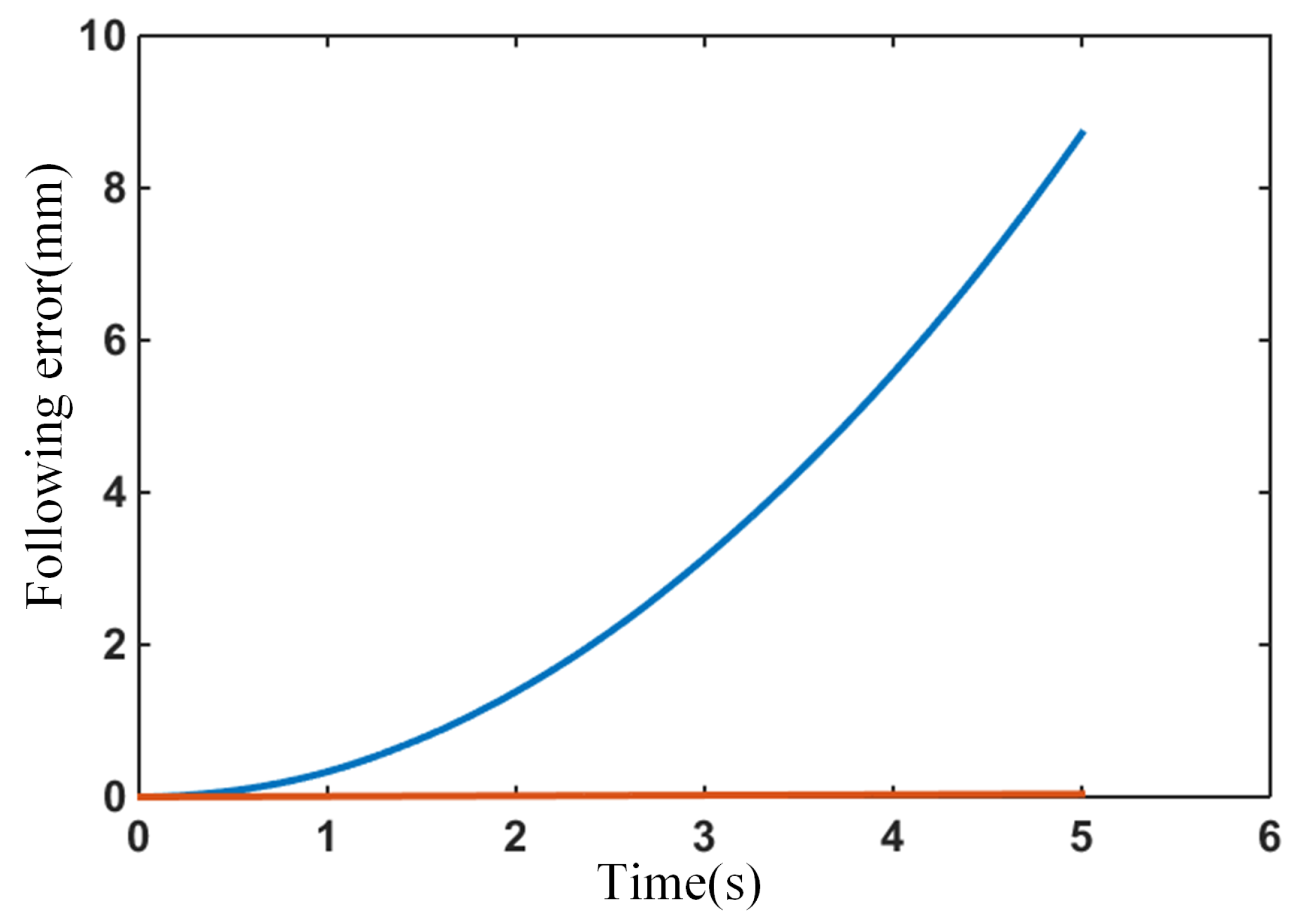
4.1. Master–Slave Control Algorithm Simulation

To form a master–slave control system, the algorithms are respectively packaged in the form of functional blocks and integrated into the TwinCAT software control system. Select each joint angle of the current position of the scanning arm as θ 1 = 90 ° , θ 2 = 75 ° , θ 3 = 90 ° , θ 4 = 105 ° , θ 5 = 90 ° , θ 6 = 90 ° , and use the randomly generated incremental sequence as the differential motion increment of the master hand to simulate the motion of the master hand. Then, the movement of the master hand is mapped to the end of the scanning arm through the master–slave mapping function, and the inverse Jacobian matrix is used to calculate the joint control amount. The master–slave control algorithm with or without an error feedback link is used to calculate the following error. The master–slave following error comparison of the two algorithms is shown in Figure 11. This algorithm has an obvious effect on reducing the following error.
In Figure 11, the following error generated by the master–slave control algorithm without the error feedback link is significantly greater than the result after adding the error feedback link. Moreover, the following error generated by the master–slave control algorithm without error feedback accumulates with the movement of the master hand. Therefore, the faster the master hand, the longer the movement time, and the larger the following error obtained by the master–slave control algorithm without error feedback. In the simulation, the given speed of the main hand is large, which means that the following error generated is also large. The error gradually accumulates and reaches 8.7 mm finally, which is unacceptable for the surgical robot. After adding the error feedback link, the error accumulation situation is greatly improved, and the maximum accumulated error is reduced from 8.7 mm to 0.04 mm, which has a significant error reduction effect.

4.2. Simulation of Admittance Controller for Arm Positioning

The admittance controller is divided into the gain part and zero pole part. The gain in the admittance controller can be combined with the equivalent stiffness of the arm for analysis. Adjusting the gain of the admittance controller can be regarded as changing the stiffness of the arm. The output of the admittance controller is the speed command, which is used as the feedforward input of the servo controller. Its integral and derivative can be respectively used as the position and acceleration feedforward input. This is actually a continuous system simulation of the trajectory planner.
First, consider the case where the admittance controller is pure gain. During the simulation process, the stiffness of the arm is fixed to 100. When the gain of the admittance controller is changed, it can be considered that the stiffness of the arm changes. Figure 12 shows the case where the admittance controller is pure gain. It can be seen from the figure that when the gain increases, the system’s low frequency gain and shear frequency will also increase, which means that the response speed and tracking accuracy of the system will increase. Moreover, the high tracking accuracy will reduce the interaction force of the system, thereby improving the dragging experience. However, the gain cannot be increased indefinitely; high gain will make the system unstable.
When the mass damping controller is introduced as the admittance controller, it needs to be discussed in two cases of stable gain and unstable gain. As shown in Figure 13a, when the gain part of the admittance controller stabilizes the system, and the mass damping controller is selected for the zero-pole part, it is equal to introducing a pole. If the pole is located after the shear frequency, it will not affect the low-frequency part of the system, and a small quality parameter needs to be set to obtain a larger pole. If the pole is located before the shear frequency, it will adversely affect the system, reducing the shear frequency and stability margin of the system, and it may even make the system unstable in severe cases. When the gain or arm stiffness is too large and the system is unstable, as shown in Figure 13b, the system can be stabilized by introducing a mass damping controller. This is actually obtaining the leading phase angle by sacrificing the shear frequency of the system, but one pole also causes the lag of the phase angle. The effects of the two cancel out each other, and it is difficult to obtain a higher stability margin.
In fact, the mass damping controller is equal to a low-pass filter for the interactive force signal. In the actual robotic arm, the interaction force is obtained by subtracting the gravity from the force sensor information, and it will be influenced by the low-frequency vibration interference of the robotic arm and the high-frequency interference of the electrical signal. The force sensor acquisition card can easily filter out high-frequency interference, and the low-frequency mechanical vibration needs to be filtered a second time. Thus, the bandwidth of the selected filter will be very low, which is equal to the pole of the mass damping controller being very small, and this will harm the system. In the above analysis, it is found that the effect of the single-pole mass damping controller is not obvious. In fact, the control of the linearized human–computer interactive admittance control system can be regarded as a problem of series system correction.
When the high gain makes the system unstable, the introduction of a lag corrector can work well, as shown in Figure 14. Lag correction is different from the single-pole mass damping controller, which can bring a larger phase angle margin through the additional zero pole points. After applying the lag correction, the system can tolerate a large system gain, which means that it can accept a greater arm stiffness.
Finally, it is found that the decisive factors for the force positioning function are actually the joint kinetic features of the robotic arm and the performance of the servo driver. The admittance controller is only used as a system correction device. For example, the following performance of the force positioning control depends on the maximum acceleration and deceleration capacity of the robotic arm joints. The admittance controller can only be used to ensure the stability of the system when the stiffness of the human arm changes drastically.

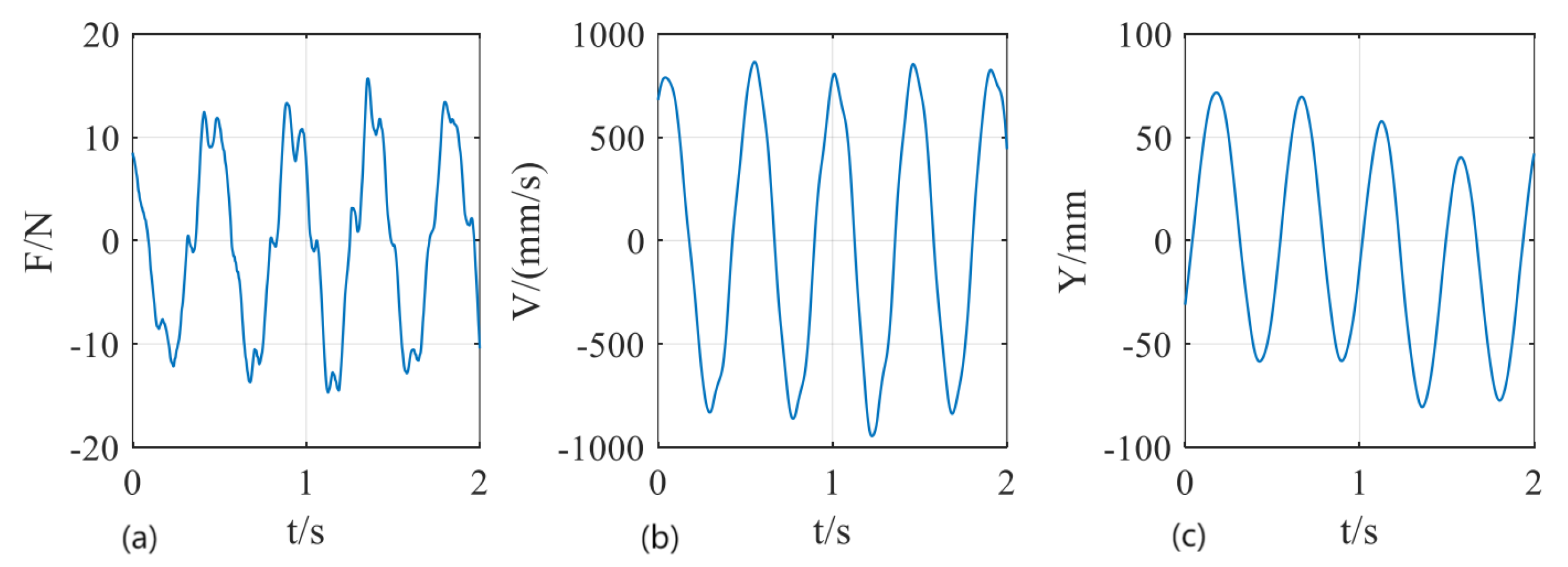
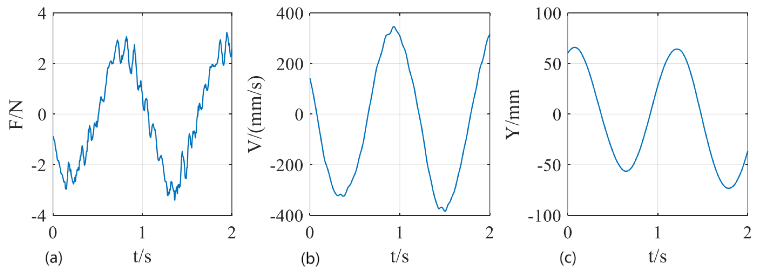
4.3. Cycled Reciprocating Motion of Dragging Tests

After comparison of the admittance controller with pure gain and with a lag corrector, cycled reciprocating motion of dragging tests are carried out. This work uses an open-loop admittance controller, with parameters d = 5 Ns/m, m = 1 kg. The two tests are situations of high dynamic performance and high sensitivity. The methods and results are shown in Figure 15 and Figure 16.
Figure 15 shows robot performance data in high dynamic performance and high stability. It can be seen that when the positioning amplitude is 50 mm, the positioning frequency reaches 2 Hz, the contact force does not exceed 15 N, and the maximum positioning speed in Cartesian space is as high as 800 mm/s. The data are stable and there is no divergence. In Figure 16, under low-speed conditions, the positioning amplitude is 50 mm, and the robot speed does not exceed 400 mm/s. The contact force does not exceed 3 N. The robot exhibits high sensitivity.

4.4. Animal Tests

Several animal renal puncture tests are carried out using the dual-armed robotic puncture system. Figure 17 shows the robotic puncture system prototype, including a US arm, a puncture arm, an operating console, and an ultrasonic monitor. Figure 18 shows the arm positioning operation (a and c) and master–slave control (b). Figure 18d shows the surgery process of the animal test. The animal tests verify the effectiveness of the dual-armed robotic puncture system.

5. Conclusions

This paper proposes a dual-armed robotic puncture system for renal puncture. For the docking process, surgeons can position the arms by dragging. For the surgery process, surgeons can use the master operator to control the arms for image guidance and adjust the needle posture, respectively. This paper describes the mechanical design, control system design, and animal tests of the dual-armed robotic puncture system, which consists of a US arm that provides ultrasound guidance and a puncture arm with a position and posture decoupling function. The control strategy of each robotic arm has been selected according to the needs of puncture surgery and verified by a simulation and tests. The results show that the dual-armed robotic puncture system in this paper is easy to operate during the docking process, and the master–slave control can meet the demand of image guidance and puncture operations. The animal tests are reported to verify the effectiveness of the system prototype.
In the future, the dual-armed robotic puncture system can be used for clinical trials, which is expected to improve the kidney retreat and the up-and-down displacement caused by breathing during the puncture process, reducing the degree of rupture of the renal parenchyma and renal capsule. This will increase the success rate of puncture surgery and reduce the occurrence of complications, so the system has good application prospects.

Author Contributions

Conceptualization, D.W.; methodology, Y.G., X.L., X.Z. and Z.Z.; software, X.L.; validation, L.C. and Z.L.; writing—original draft preparation, W.J. and Y.G.; writing—review and editing, Y.G.; project administration, W.D. All authors have read and agreed to the published version of the manuscript.

Funding

This research was funded by the National Key Research and Development Program of China (Grant No. 2017YFB1303101).

Informed Consent Statement

The study was conducted according to the guidelines issued by the Ethics Committee of Huazhong University of Science and Technology (Project Partner) for National Key Research and Development Program of China 2017YFB1303101.

Conflicts of Interest

The authors declare no conflict of interest.

References

  1. Jun, J.; Yaqing, C.; Yongchang, Z. Analysis of complications in ultrasound-guided percutaneous renal biopsy. Chin. J. Ultrasound Med. 2006, 22, 858–860. [Google Scholar]
  2. Whittier, W.L.; Korbet, S.M. Timing of complications in percutaneous renal biopsy. J. Am. Soc. Nephrol. 2004, 15, 142–147. [Google Scholar] [CrossRef] [PubMed] [Green Version]
  3. Stoianovici, D.; Cleary, K.; Patriciu, A.; Mazilu, D.; Stanimir, A.; Craciunoiu, N.; Watson, V.; Kavoussi, L. AcuBot: A robot for radiological interventions. IEEE Trans. Robot. Autom. 2003, 19, 927–930. [Google Scholar] [CrossRef]
  4. Stoianovici, D.; Jun, C.; Lim, S.; Li, P.; Petrisor, D.; Fricke, S.; Sharma, K.; Cleary, K. Multi-imager compatible, MR safe, remote center of motion needle-guide robot. IEEE Trans. Biomed. Eng. 2017, 65, 165–177. [Google Scholar] [CrossRef] [PubMed]
  5. Mitchell, B.; Koo, J.; Iordachita, I.; Kazanzides, P.; Kapoor, A.; Handa, J.; Hager, G.; Taylor, R. Development and application of a new steady-hand manipulator for retinal surgery. In Proceedings of the 2007 IEEE International Conference on Robotics and Automation, Rome, Italy, 10–14 April 2007; pp. 623–629. [Google Scholar]
  6. Üneri, A.; Balicki, M.A.; Handa, J.; Gehlbach, P.; Taylor, R.H.; Iordachita, I. New steady-hand eye robot with micro-force sensing for vitreoretinal surgery. In Proceedings of the 2010 3rd IEEE RAS & EMBS International Conference on Biomedical Robotics and Biomechatronics, Tokyo, Japan, 26–29 September 2010; pp. 814–819. [Google Scholar]
  7. He, X.; Roppenecker, D.; Gierlach, D.; Balicki, M.; Olds, K.; Gehlbach, P.; Handa, J.; Taylor, R.; Iordachita, I. Toward clinically applicable steady-hand eye robot for vitreoretinal surgery. In Proceedings of the ASME International Mechanical Engineering Congress and Exposition, Houston, TX, USA, 9–15 November 2012; Volume 45189, pp. 145–153. [Google Scholar]
  8. Kettenbach, J.; Kronreif, G. Robotic systems for percutaneous needle-guided interventions. Minim. Invasive Ther. Allied Technol. 2015, 24, 45–53. [Google Scholar] [CrossRef] [PubMed]
  9. Zhou, Y.; Thiruvalluvan, K.; Krzeminski, L.; Moore, W.H.; Xu, Z.; Liang, Z. CT-guided robotic needle biopsy of lung nodules with respiratory motion—Experimental system and preliminary test. Int. J. Med. Robot. Comput. Assist. Surg. 2013, 9, 317–330. [Google Scholar] [CrossRef] [PubMed]
  10. Hungr, N.; Bricault, I.; Cinquin, P.; Fouard, C. Design and validation of a CT-and MRI-guided robot for percutaneous needle procedures. IEEE Trans. Robot. 2016, 32, 973–987. [Google Scholar] [CrossRef]
  11. Patel, N.A.; Azimi, E.; Monfaredi, R.; Sharma, K.; Cleary, K.; Iordachita, I. Robotic system for MRI-guided shoulder arthrography: Accuracy evaluation. In Proceedings of the 2018 International Symposium on Medical Robotics (ISMR), Atlanta, GA, USA, 1–3 March 2018; pp. 1–6. [Google Scholar]
  12. Stoianovici, D.; Kim, C.; Srimathveeravalli, G.; Sebrecht, P.; Petrisor, D.; Coleman, J.; Solomon, S.B.; Hricak, H. MRI-Safe Robot for Endorectal Prostate Biopsy. IEEE/ASME Trans. Mechatron. 2014, 19, 1289–1299. [Google Scholar] [CrossRef] [Green Version]
  13. Boctor, E.M.; Fischer, G.; Choti, M.A.; Fichtinger, G.; Taylor, R.H. A dual-armed robotic system for intraoperative ultrasound guided hepatic ablative therapy: A prospective study. In Proceedings of the IEEE International Conference on Robotics and Automation, ICRA’04, New Orleans, LA, USA, 26 April–1 May 2004. [Google Scholar]
  14. Hong, J.; Dohi, T.; Hashizume, M.; Konishi, K.; Hata, N. An ultrasound-driven needle-insertion robot for percutaneous cholecystostomy. Phys. Med. Biol. 2004, 49, 441–455. [Google Scholar] [CrossRef]
  15. Kettenbach, J.; Kronreif, G.; Figl, M.; Fürst, M.; Birkfellner, W.; Hanel, R.; Bergmann, H. Robot-assisted biopsy using ultrasound guidance: Initial results from in vitro tests. Eur. Radiol. 2005, 15, 765. [Google Scholar] [CrossRef]
  16. Bassan, H.; Hayes, T.; Patel, R.V.; Moallem, M. A Novel Manipulator for 3D Ultrasound Guided Percutaneous Needle Insertion. In Proceedings of the IEEE International Conference on Robotics & Automation, Rome, Italy, 10–14 April 2007. [Google Scholar]
  17. Ghodoussi, M. Robotic surgery-the transatlantic case. In Proceedings of the IEEE International Conference on Robotics & Automation, Washington, DC, USA, 11–15 May 2002. [Google Scholar]
  18. Marescaux, J.; Rubino, F. The ZEUS robotic system: Experimental and clinical applications. Surg. Clin. N. Am. 2003, 83, 1305–1315. [Google Scholar] [CrossRef]
  19. Guthart, G.S.; Salisbury, J.K. The IntuitiveTM telesurgery system: Overview and application. In Proceedings of the IEEE International Conference on Robotics & Automation, San Francisco, CA, USA, 24–28 April 2000; pp. 618–621. [Google Scholar]
  20. Goonewardene, S.S.; Catterwell, R.; Brown, M.; Challacombe, B. Robotic surgery with the Da Vinci Xi: Simultaneous upper and lower tract surgery. J. Robot. Surg. 2016, 11, 373–374. [Google Scholar] [CrossRef]
  21. Hannaford, B.; Rosen, J.; Friedman, D.W.; King, H.; Roan, P.; Cheng, L.; Glozman, D.; Ma, J.; Kosari, S.N.; White, L. Raven-II: An Open Platform for Surgical Robotics Research. IEEE Trans. Biomed. Eng. 2013, 60, 954–959. [Google Scholar] [CrossRef] [PubMed]
  22. Konietschke, R.; Hagn, U.; Nickl, M.; Jorg, S.; Hirzinger, G. The DLR MiroSurge—A robotic system for surgery. In Proceedings of the 2009 IEEE International Conference on Robotics and Automation, ICRA’09, Kobe, Japan, 12–17 May 2009. [Google Scholar]
  23. Hagn, U.; Konietschke, R.; Tobergte, A.; Nickl, M.; Jörg, S.; Kübler, B.; Passig, G.; Gröger, M.; Fröhlich, F.; Seibold, U.; et al. DLR MiroSurge: A versatile system for research in endoscopic telesurgery. Int. J. Comput. Assist. Radiol. Surg. 2010, 5, 183–193. [Google Scholar] [CrossRef] [Green Version]
  24. Aksungur, S. Remote Center of Motion (RCM) Mechanisms for Surgical Operations. Int. J. Appl. Math. Electron. Comput. 2015, 3, 119. [Google Scholar] [CrossRef]
  25. Newman, W.S. Stability and Performance Limits of Interaction Controllers. J. Dyn. Syst. Meas. Control 1992, 114, 563–570. [Google Scholar] [CrossRef]
  26. Kazerooni, H.; Snyder, T.J. Case Study on Haptic Devices: Human-Induced Instability in Powered Hand Controllers. J. Guid. Control. Dyn. 1995, 18, 108–113. [Google Scholar] [CrossRef]
Figure 1. Dual-arm puncture robot system architecture.
Electronics 11 00740 g001
Figure 2. Puncture arm structure design. (a) Arm decoupling mechanism; (b) Wrist RCM mechanism; (c) Puncture arm structure.
Electronics 11 00740 g002
Figure 3. D-H coordinate system of the puncture arm.
Electronics 11 00740 g003
Figure 4. The structure and D-H coordinate system of the scanning arm. (a) Scanning arm structure; (b) Scanning arm link coordinate system.
Electronics 11 00740 g004
Figure 5. Dual-arm puncture system control architecture.
Electronics 11 00740 g005
Figure 6. Master–slave control of inverse Jacobian matrix with error compensation.
Electronics 11 00740 g006
Figure 7. Human–computer interaction admittance control principle.
Electronics 11 00740 g007
Figure 8. Equivalent control block diagram of human–computer interaction system.
Electronics 11 00740 g008
Figure 9. Human–computer interactive admittance control system after linearization approximation.
Electronics 11 00740 g009
Figure 10. The link combinations in kinematics.
Electronics 11 00740 g010
Figure 11. Comparison of following error with (red line) and without (blue line) error feedback link.
Electronics 11 00740 g011
Figure 12. Admittance controller in the case of pure gain.
Electronics 11 00740 g012
Figure 13. Analysis of the introduction of mass damping controller. (a) Stable gain introduces mass dampling controller; (b) Unstable gain introduces mass dampling controller.
Electronics 11 00740 g013
Figure 14. Analysis of lag compensation as admittance controller.
Electronics 11 00740 g014
Figure 15. High dynamic performance motion test of dragging operation: (a) contact force; (b) robot velocity; (c) robot position.
Electronics 11 00740 g015
Figure 16. High sensitivity motion test of dragging operation: (a) contact force; (b) robot velocity; (c) robot position.
Electronics 11 00740 g016
Figure 17. The prototype of dual-armed robotic puncture system and system composition.
Electronics 11 00740 g017
Figure 18. Process of the animal tests. (a) US arm docking operation; (b) master–slave control of US arm for image guidance; (c) puncture arm docking operation; (d) the surgery process of the animal test.
Electronics 11 00740 g018
Table 1. D-H parameters of the puncture arm expressed by generalized variables.
Link1233′456
θ i q 1 q 2 + 90 ° q 3 q 2 90 ° q 3 q 4 90 ° q 5 + 90 ° q 6 + 90 °
Table 2. D-H parameters of the scanning arm represented by joint variables.
Link123456
θ i θ 1
( + 90 ° )
θ 2
( + 90 ° )
θ 3 θ 4
( + 90 ° )
θ 5
( 90 ° )
θ 6
( + 90 ° )
Publisher’s Note: MDPI stays neutral with regard to jurisdictional claims in published maps and institutional affiliations.

