1. Introduction
Over recent years, the whole world has been transferring to renewable energy sources to generate electricity in order to minimize carbon emissions [
1,
2]. Renewable energy sources have several challenges in terms of availability, dependability, and control [
3,
4]. The most control problem facing Distributed Energy Resources (DERs) is the synchronization to the grid. The used tool to realize this synchronization is the Phase-locked loop (PLL) control is used to estimate the grid phase angle, hence generating the same phase from the inverter is possible.
The change of impedance in the distribution system, considered the foremost challenge, is facing the PLL controller of the Distributed Generation (DG). This consecutive change has occurred due to loading condition change, which is the nature of many types of loads, such as domestic load [
5].This continuous change in the grid impedance, especially in weak grids, creates the need for adaptive controllers and online monitoring algorithms.
In this study [
6], a review of the micro-grid control functions and the time of each control function is provided. For example, the current control should be instantaneous, while the Volt/Var control timing should be in the ms range, and so on. In addition, ref. [
7] provides a brief overview of the limitations and benefits of several approaches for estimating grid-impedance.
In this paper [
8], the LCL-filter and Current Control Loop (CCL) designs are proposed to reduce the negative effect of the PLL on the system stability considering the weak grids; this study does not consider the voltage at the PCC in the design parameters; however, it is a factor affected by the grid impedance (SCR). The design of the LCL filter enhances the Total Harmonic Distortion (THD) of the injected voltage. The used control technique for CCL is the feed-forward control; this technique is studied for different SCR to prove the effectiveness. Ref. [
9] provides a robust control method to stabilize the inverter with LCL-filter by active damping. The inverter used is the current-controlled inverter, a minor type of inverter used in the existing system. In [
10], virtual impedance control is proposed to solve the stability problems in the weak grids, and [
11] an active damping controller is introduced to enhance the performance of the PLL; however, the internal structure of the PLL is not changed because, in the active damping methods, the change in internal structure is needed.
In ref. [
7], a model has been suggested to estimate the grid impedance and drawbacks. It also introduces a method to design a current controller gain based on the parameters for the LCL filter. This method does not consider the bandwidth of the PLL, which affects the whole system’s stability. In this study, two cascaded loops are used to control the inverter. The first is the fast inner current controller, and the outer is the DC voltage controller; however, the criteria to judge the stability is impedance-based, which considers the output impedance of the inverter and the grid.
Ref. [
12] has introduced an assessment of the PLL in the weak grid by the small-signal stability study for the DG system. This study introduced the effect of increasing the PLL bandwidth on the weak grids via indicating that some of the eigenvalues tend to move towards instability, which endangers the whole stability of the systems. However, selecting the LCL-filter values is not indicated. A solution to decrease the negative impact of a weak grid on the PLL performance is not indicated using the small-signal stability study. In [
13,
14,
15], an extensive analysis is performed to assess the effect of PLL dynamics on the weak grids. These studies conclude that, when ignoring the grid impedance, the output of the converter will be affected due to the PLL controller. This negative impact is proved by the small-signal stability studies, and ref. [
16] introduces modelling and stability analysis for the voltage source converter connected to the weak grid; the used case study here is the wind turbines with multi VSCs connected in the weak grid.
Ref. [
17] has introduced a control method to improve the weak grid stability by creating an equivalent model for the connected DG system. This control method is based on the system voltage. The study does not show the effect of this new control system on the small-signal stability. The suggested model in [
15] introduced a small signal impedance of the grid-connected inverter, but neither the whole system nor the PLL is not taken into consideration for the small-signal stability study model; the effect of the dynamic of the PLL in weak grids is included in this analysis is not enough. The model presented in [
18] is the unified impedance of the grid-connected voltage source. Two types of models are introduced. Firstly, the impedance-based model is used, while the second one is based on the harmonic balance; this paper introduces the two current control loops that are introduced in this paper with an L-filter; the effect of PLL dynamics is also included, but this paper does not introduce a framework to regulate these dynamics or enhance the overall system stability. The synchronization instability from the point of the common coupling point due to the weak grid and PLL design the inverter used here [
19] is the impedance-based model. However, using the DC voltage feed-forward term in the current control loop, this paper [
20] introduces a control algorithm consisting of two parts. The first part is the power loop to regulate the frequency and angle of the output power and those control loops with the objective of self-synchronization capability. Another method to overcome the weak grid problem is to design the control algorithm to simulate the actual synchronous generator to increase the system strength, such as [
21,
22,
23].
Ref. [
24] has proposed a consensus algorithm to determine the compensation effort of the group of connected units according to the power characteristic of each unit and the other connected units; this is a distributed controller. However, this scheme does not consider the grid weakness that may result in stability issues for all systems.
The grid impedance and loading conditions should not be ignored when designing the PLL. A lot of research introduces ways to enhance this issue. However, in many cases, the change of the loading conditions effect on the grid impedance is not taken into consideration, so, in this paper, a new framework to enhance the small-signal stability of the PLL controller in the weak grid by updating the controller’s gains, the updating process is based on system parameters estimation and impedance estimation.
The rest section of this paper is organized as follows:
Section 1 contain the introduction;
Section 2 introduces the system description, the grid weakness and the tuning procedure for the system controllers;
Section 3 introduces the proposed algorithm to enhance the controller’s performance, small signal stability for the system and the system stability criteria;
Section 4 introduces the case study used to evaluate the effectiveness of the proposed algorithm and the small-signal stability study results; and
Section 5 contains the conclusions of this study.
2. System Description
The commonly used (Photo-Voltaic (PV) or Wind Turbine (WT)) topology consists of two converters: grid side converter and generator side converters such as the regular PV topology or typed four wind turbine [
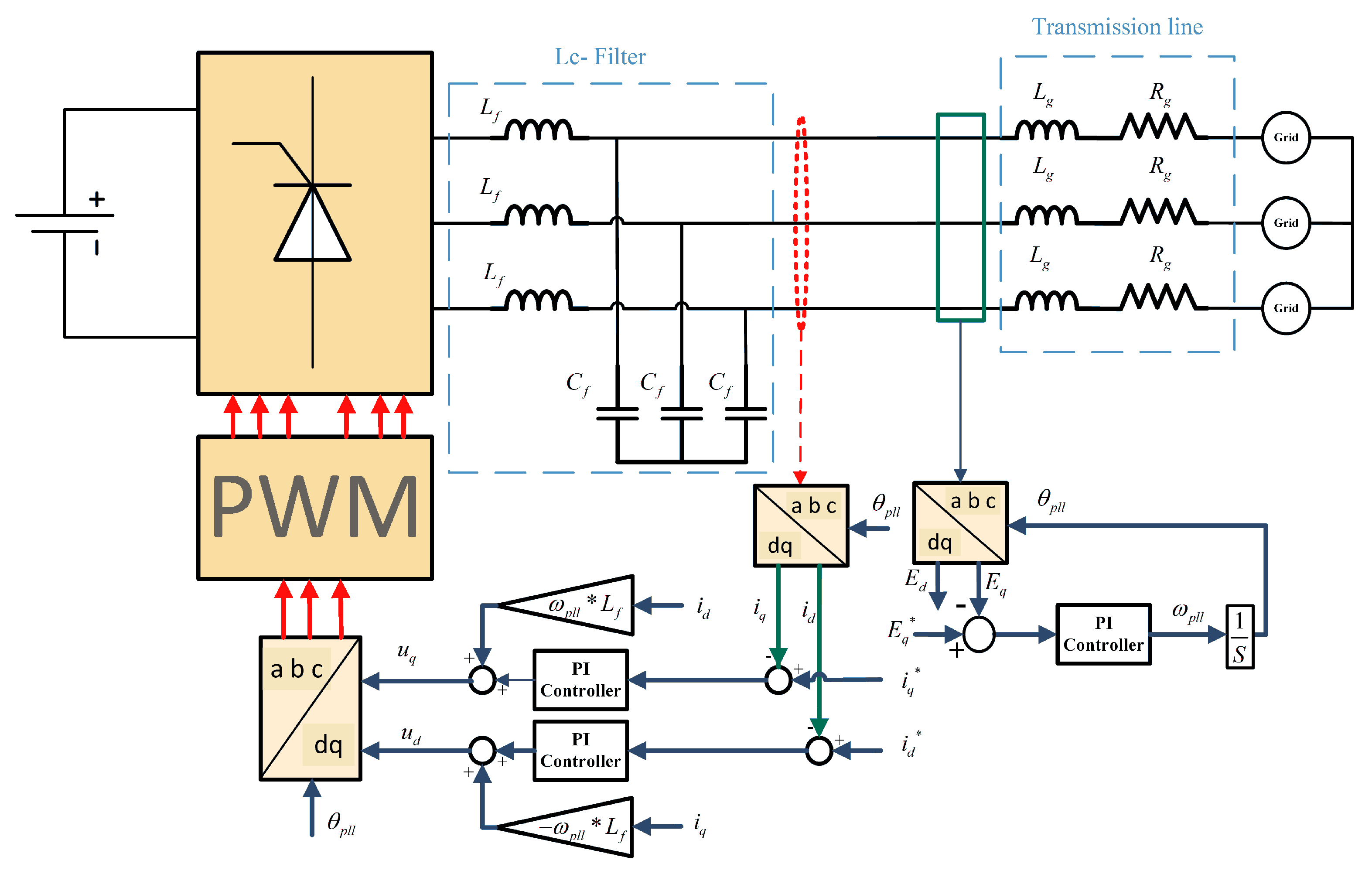
25]. The topologies mentioned above share the same controller loops (inner control loop and outer control loop) and the same pulse-width modulation (PWM) technology as shown in
Figure 1, which shows the system under study.
Figure 1 shows the system under study. This system is simulated on the Matlab Simulink software. It contains the voltage source, which simulates the wind or the PV output. The output energy of these sources is fed into the grid side converter and then to the LC filter to reduce the THD of the generated wave. The grid side converter is typically controlled through two control loops; the inner control loop (the current control loop) and the outer control loop (voltage control loop) [
26].
In this study, only the inner control loop is simulated to reduce the complexity of the system matrix. The tuning of the inner control loop is introduced in the next section. The Park–Clark transformation matrix converts the ABC-Vector Scheme voltage sequence to the DQ0-Vector Scheme voltage to be controlled through the inner control loop and then transforms the DQ0 output signal from the current control loop to the ABC signal used in PWM. This transformation matrix uses the output phase angle of the PLL control loop.
The PLL control loop is a crucial part of those topologies [
27], as the PLL is a signal tracking tool to deliver the right grid angle in optimized time to avoid losing stability. The PLL gains deplaned to the grid impedance, so the controller performance is not the same because of the continuous change in grid impedance. From the previous discussion, we can deduce that the PLL tuning affects the inner control loop stability and the whole system stability so an adaptive PLL system based on the small-signal stability study is proposed.
2.1. Grid Weakness
One of the challenges facing Distributed Energy Resources (DER) Technologies is the availability of energy sources. In most cases, the DER is located in remote areas, which makes the Grid’s Short Circuit Ratio (SCR) small. Thus, the PLL stability is affected; hence, it is necessary to modify the controller damping factor to ensure stability by the small-signal stability study.
The grid weakness is estimated by the SCR ratio of less than 10 in the medium voltage systems. The grid is weak, as reported in [
28]. SCR is calculated as in (
1). When supplied by a constant voltage, this ratio is affected by the change in load centres (constant power loads). Due to the constant change, PLL stability is strongly affected:
In many cases, we need to calculate the critical value of at a specific SCR to modify the controller parameters to stabilize the system.
2.2. Tuning the Controller System
The following two sections introduce the CCL and the PLL tuning technique. The CCL objective is the speed response, while the PLL objective is the stability of the operation.
2.2.1. CCL Tuning Process
For the system used in this study (
Figure 1), the Kerchief voltage equations as in Equations (
2) and (
3) are used. These equations are converted to the
-reference frame using the Park and Clark transformation matrix; then, (
4) is obtained:
If it is assumed that
,
, as given in (
5), Equation (
4) can be rewritten in the s-domain (
6). This equation is rewritten to get (
7). The transfer function of the controlled system with the assumption (
5) is given by (
8):
The controller type used to regulate the CCL is the PI controller; thus, the equation that represents this controller is given by (
9), where the
and
are indicated in (
10), and the transfer function of the controller is given by (
11):
The used tuning method to achieve the speed requirement of the CCL is “modulus optimum” [
29]. Due to its simplicity and speed, this approach is widely used; however, the
value is neglected. The cut-off frequency
rad/sec and the damping factor
with the value of
, the controller gains
,
will be calculated as (
12) and (
13):
2.2.2. Pll Tuning Process
In this section, the way to tune the PLL is introduced. As known from the Park and Clark transformation, the theory that relies on getting the phase angle can be proved using (
14); then, if
is changed by
and
is also changed by
, Equation (
15) can be obtained. On a basis of
, the
can be collected:
As mentioned earlier, the final goal is to get the
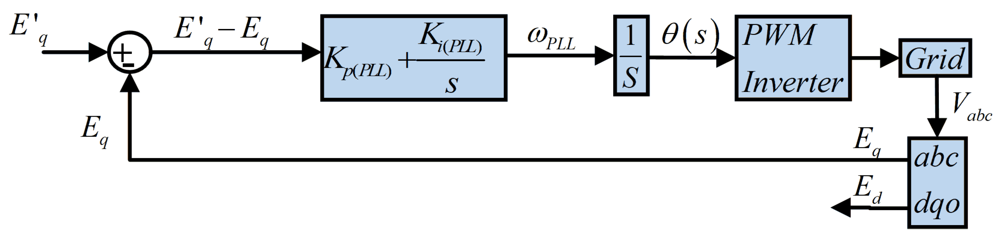
. As shown in
Figure 2, the transfer function will be as in (
16), where the
, where the
is the maximum voltage of the grid. The denominator of the
is
, comparing this with the standard denominator of the second order system, which is
, the
will be as shown in (
17):
To tune the PI controller of the PLL, the
must be determined, since the main goal of the PLL tuning process is optimum regulation and stability. The method used for this objective is “Symmetrical Optimum” (SO) [
29]. In the SO method, the plant transfer function is rewritten as
, where
is the sampling delay and the controller transfer function is
, and the open-loop transfer function is given by (
18). Comparing (
19) Bode diagram with the standard Bode diagram of the 3rd order system, the cut off frequency (
), the damping factor (
) are collected. New scale factor
is identified to initialize the relation between
and
. The resultant equations given by (
19) use
to manage the control process to be easier by changing one variable, which is the
; then, the
is determined by the already identified sampling time
:
In (
19), the PLL algorithm is made to be dynamic according to the
(the maximum voltage) at the PCC. The change in the SCR affects the
. Hence, it dynamically changes according to the change of the SCR ratio or the grid weakness.
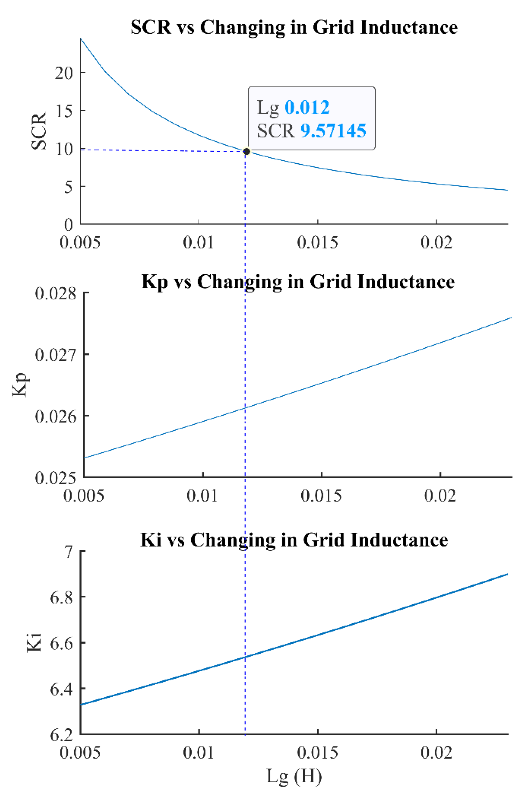
Figure 3 indicates the change in the PLL gains according to the change in grid inductance. From this figure, the grid is weak if the SCR value is less than ten. In this case, the PLL controller gains should be changed as (
19). In
Figure 3, the
is calculated by subtracting the voltage droop at the transmission line from the nominal voltage, and the damping ratio (DRT) of the PLL is kept at the value of 0.5. In the proposed algorithm, the DRT is changed to maintain the small-signal stability at reasonable limits.
3. Solution Methodology
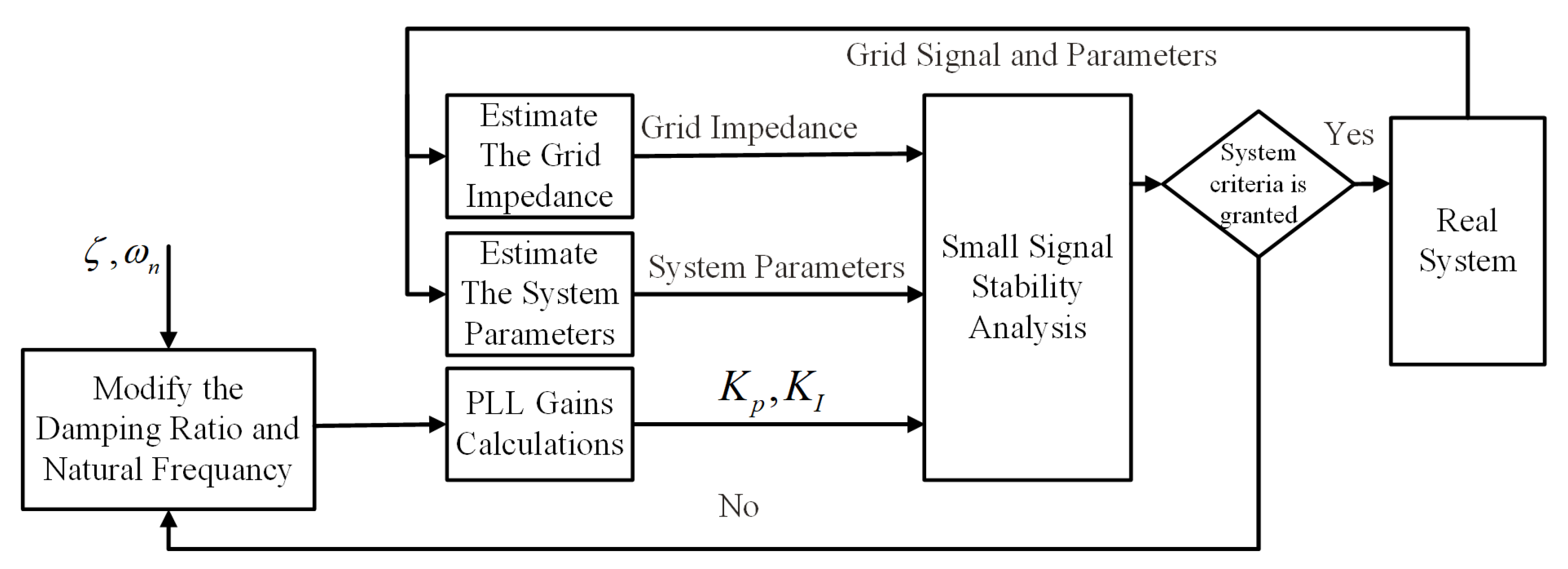
As shown in
Figure 4, the small-signal stability model regulates the system’s performance. The grid estimation method based on the wavelet is used to update the value corresponding to the state matrix to complete this system as intended. The system parameters in the state matrix need to be updated through another estimation process. Those two estimation methods are now possible because of the increase in the number of Digital relays, the phasor measurementunits (PMUs), and micro phasor measurement units (µPMUs), which are used in the distribution systems [
30,
31].
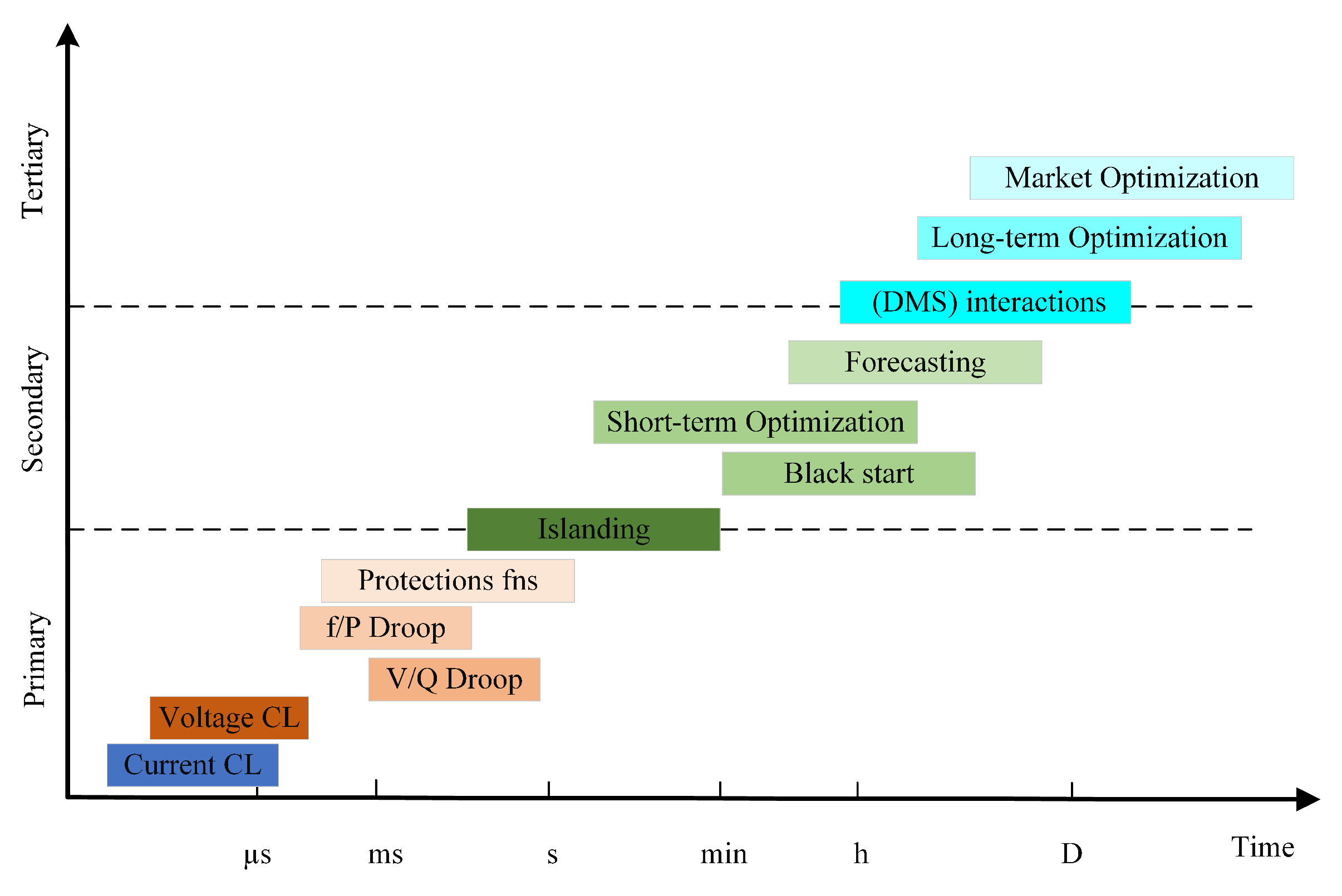
3.1. Control Functions Time Frame
There are three control levels in microgrids and distribution systems, which are referred to as the hierarchical Microgrid Management System (MGMS). Those management functions are performed either in a centralized or distributed way. The primary control level contains all functions executed in the range from microsecond to 1 s, such as volt/var control algorithms or droops control and frequency control functions or f/p. The control level contains various protection functions. The range may also contain the grid connection and disconnection function. A secondary control level can be executed in a range from 1 s to several hours. Those functions are grid connections or disconnections and the optimization functions, which enhance the efficiency of the used resources, the black start, and restoration processes are in this time range. Load forecasts and various short-time economic studies are performed in this range. All procedures take hours or days to complete, such as market analysis and long-term forecasting studies, as well as a distribution management system, which are included in the tertiary control level.
Figure 5 describes the timing for all those functions.
In the proposed methodology, the control level for the inverter is in the primary control level. In contrast, the methodology responsible for adjusting the controllers’ gains is in the secondary control level. The secondary control function is triggered by changing the estimated impedance by offsetting of the maximum Thevenin impedance in the controlled system.
3.2. The Small Signal Stability Model
The small-signal stability is performed on the investigated system to ensure stability under small changes. The system is modelled in mathematical equations as (
11); then, the linearization process is performed to get the state matrix as given in (
20):
To evaluate the eigenvalues for the state matrix, three kinds of parameters must be known: firstly, the grid parameters (grid resistance, inductance), (LCL- filter resistance, inductance, and capacitance), (nominal frequency rad/sec), secondly, the controllers’ gains (inner current controller proportion, integral gains), (PLL controller proportion, integral gains), thirdly operating point (the grid voltages and currents in the DQ0-reference frame).
The filter parameters are known in the design stage as [
32], while the grid parameters are estimated, as mentioned earlier, according to the load profile. Finally, the operating points and controllers’ gains are updated from the existing system at every cycle when needed.
System stats are , the small change in the voltage and the current in the converter reference frame, , , the voltage and current of the grid in the grid reference frame, and are , respectively, in a converter reference frame. is the change between the grid and the converter reference frames, in order to linearize the system, it is assumed that .
3.3. Getting SSSS Parameters
Many techniques have been used to estimate the grid-impedance [
5]. This study uses a technique based on selected harmonic injection [
33]. Through this technique, the harmonic of the selected order is injected through the inverter; then, the current and the voltage are measured. DFT is used to get the specific harmonics. There is no need to disconnect the DG; it can be used online.
The parameters of the study-targeted system are the controllers’ gains for the CCL, the PLL, and the LC-filter impedance; these parameters are known already through the design stage or from the controller itself. In addition, the other system parameters are the grid voltage and currents in the DQ0-reference frame, which can be obtained directly from the controllers.
3.4. System Stability Criteria
To judge if the system is within the stable region, the parameter to be monitored is the DRT. To decrease the inter-area oscillations, the minimum DRT for the overall system is , which is equivalent to degrees, which is the maximum angle .
4. Case Study
In this section, the case study is used to prove the effectiveness of the proposed algorithm; this section is divided into four subsections. The first subsection is the ZBUS algorithm, the second subsection effect shows the effect of changing the damping ratios, and testing the algorithms at bus #18 in the selected study system, the third subsection shows effect the proposed algorithm on IEEE 33 bus system, and the fourth subsection shows the comparison between using and not using the algorithm.
4.1. Zbus Algorithm
The medium voltage IEEE 33-bus system in which its data can be found [
27,
34,
35,
36,
37] is used to test the proposed algorithm. Firstly, the grid impedance at every bus must be identified to test the algorithm. Thevenin impedance is calculated for the system considering the constant loads model. The ZBUS algorithm can calculate the Thevenin impedance at each bus [
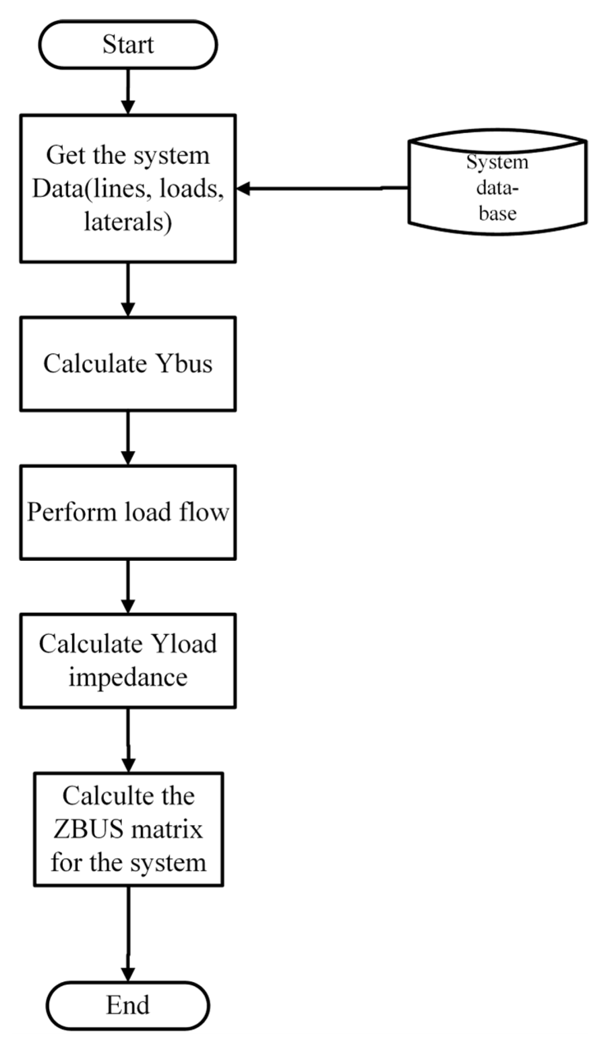
37].
Figure 6 indicates the flowchart used to calculate the ZBUS. The diagonal of the ZBUS matrix is the Thevenin impedance at each bus. Hence, the equivalent Thevenin impedance is calculated at any bus with respect to the load profile change. This study considers this method to get ZBUS as it is used already to calculate the faults at any bus; hence, no additional algorithms are needed. Hence, the time required to execute the whole system sample is decreased.
Table 1 indicates the Thevenin impedance at all buses in the studied system.
From
Table 1, it can be observed that five buses have less than 10 SCRs. Those buses are 17, 18, 31, 32, 33 in a
loading condition. The SCR ratio is worse if the change in loads is considered according to the load profile as shown in Figure 9.
4.2. Testing the SSS Algorithm
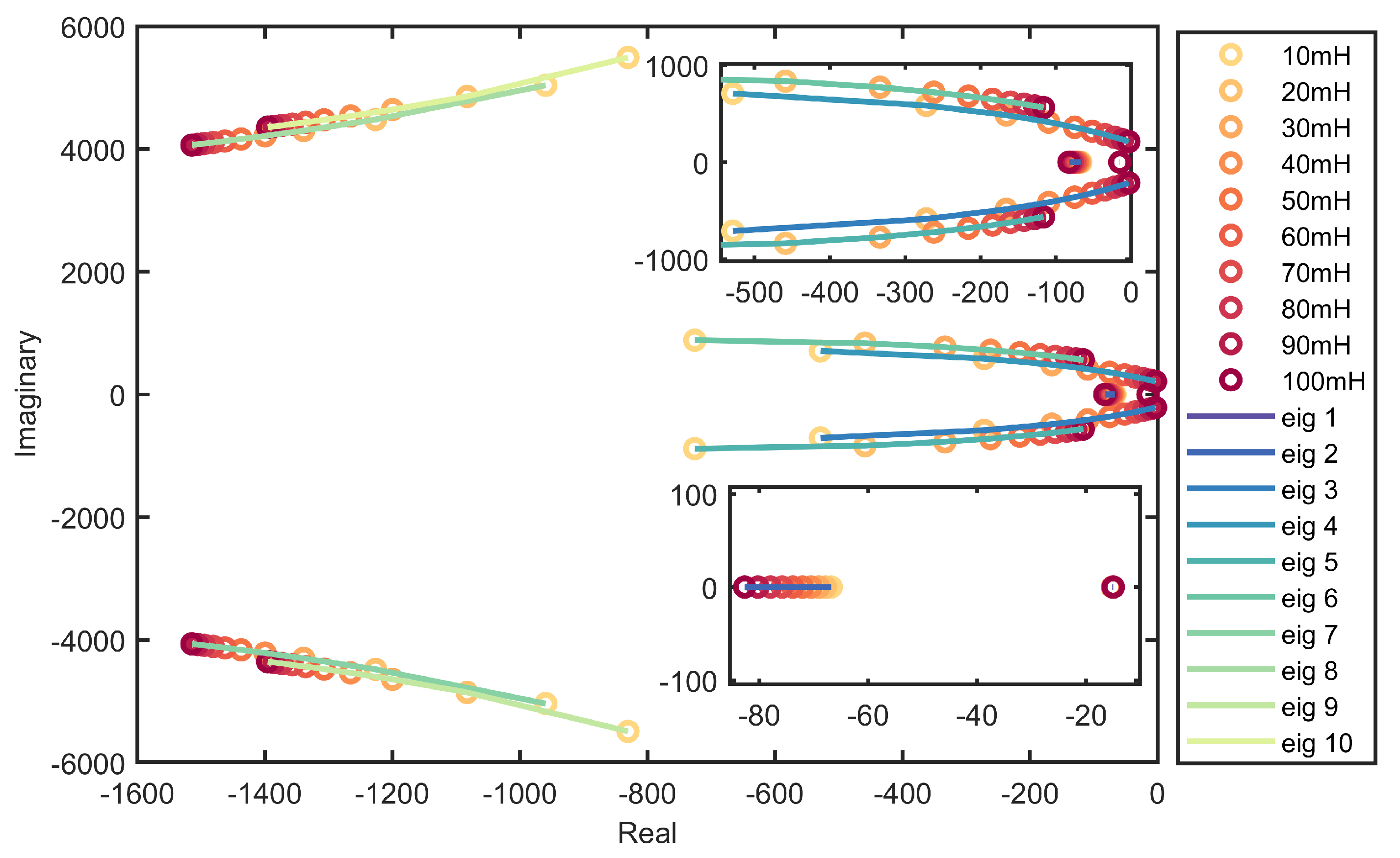
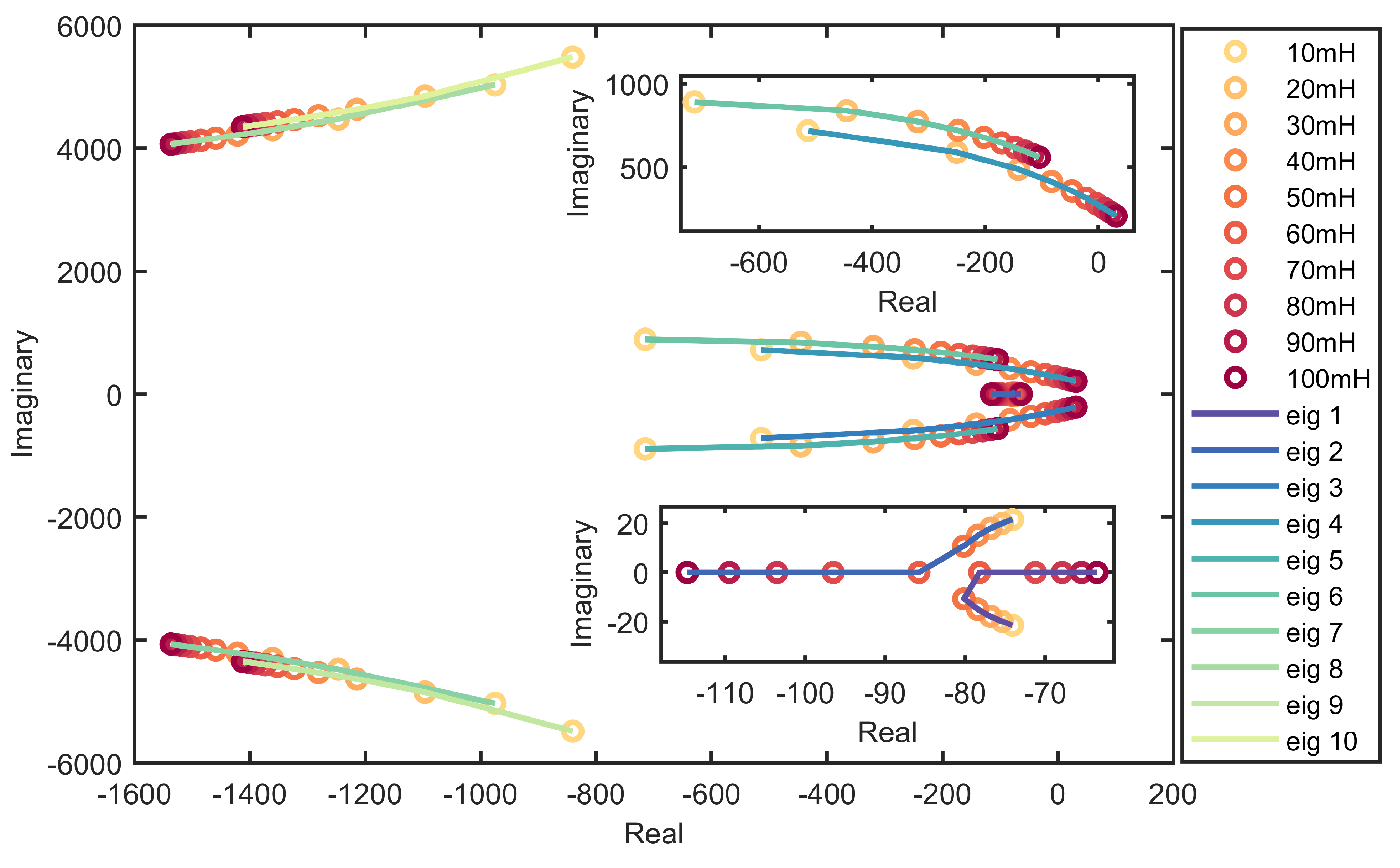
The small-signal stability study is tested if the grid inductance increased from 10 mH to 100 mH. This change is performed at DRT = 0.2. The results are shown in
Figure 7. This figure shows that two eigenvalues (Eig 3, Eig 4) are critical eigenvalues because of their moving trend. Those eigenvalues can lead to instability conditions. If the
(PLL controller damping factor) changed from 0.2 to 0.4, the system would return to a stable condition with the same grid inductance range, as shown in
Figure 8. This figure proves the main idea of the proposed algorithm, which is controlling the system small signal stability that faces small changes according to the loading conditions of the systems. The parameters used in this case study for the DER are indicated in
Table 2.
4.3. Effect of the Proposed Algorithm on the Test System Considering the Load Profile
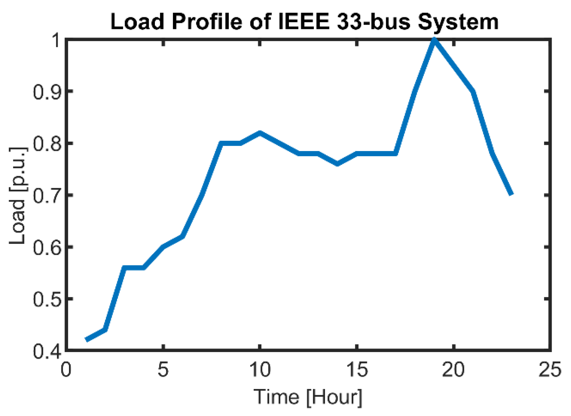
To test the algorithm, the DG is added at bus #18 as it has the minimum SCR among all buses. According to the loading conditions indicated in
Figure 9, the system impedance is changed. The system is examined as the grid impedance changes like the actual loading condition.
Thevenin impedance is multiplied by the values of the load profile shown in
Figure 9. According to
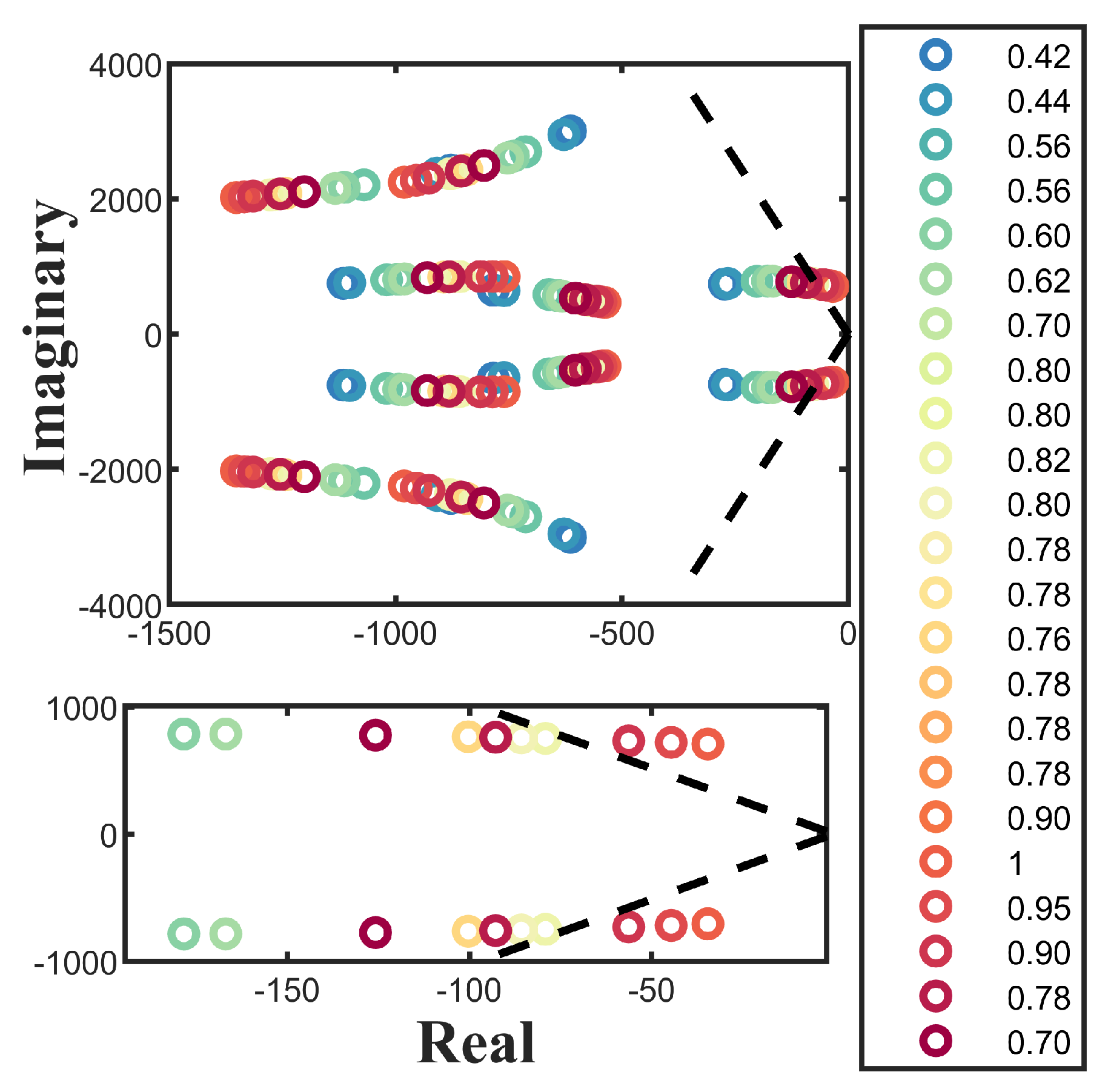
Table 1, the highest loading condition is bus #18, which is used to test the proposed methodology. The eigenvalues of IEEE 33-bus at bus #18 are indicated in
Figure 10.
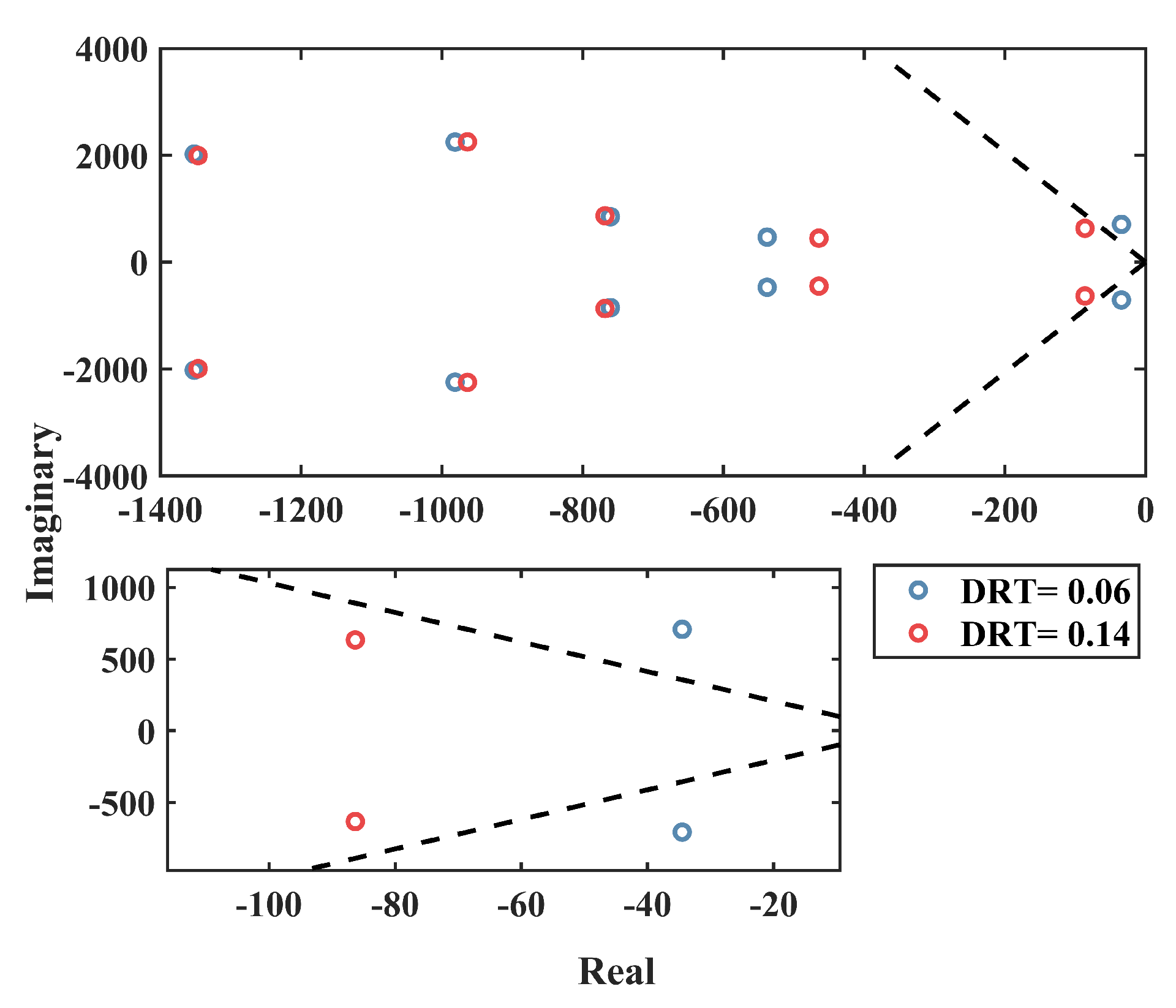
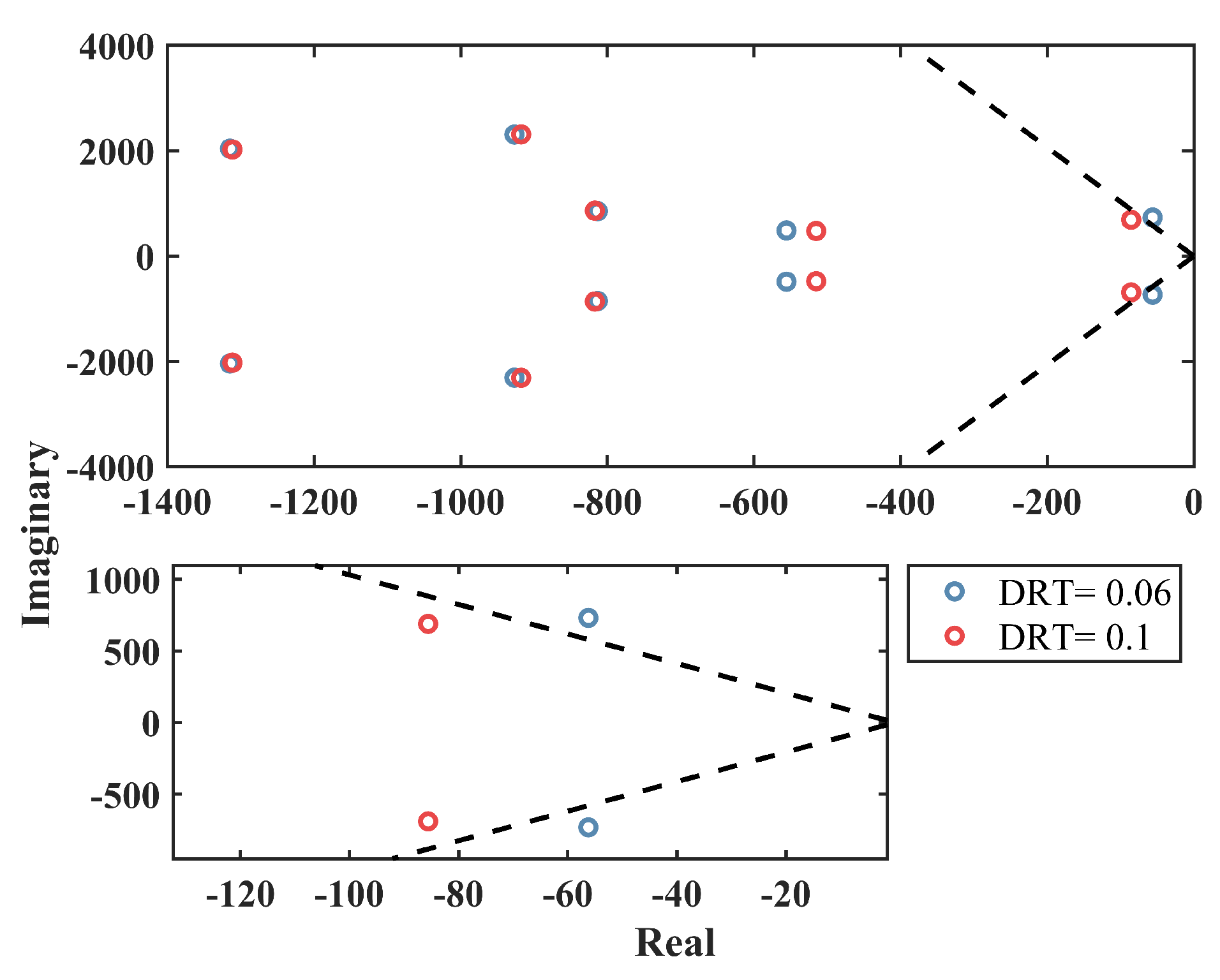
From
Figure 10, three loading conditions need to change the DRT to maintain the stability at the controlled value according to the system stability criteria mentioned before. Hence, the damping factor of the PLL needs to change at 0.9, 0.95, 1 p.u. At these loading conditions, the algorithm is activated to regulate the PLL gains to maintain the earlier stability margin. The PLL damping factor is increased to maintain the eigenvalues in the 84.46-degree envelope. The required DRT for 0.9, 0.95, 1 p.u. (loading conditions) at the 18, 20, 19 h are changed from 0.06 to 0.1, 0.13, 0.14, respectively.
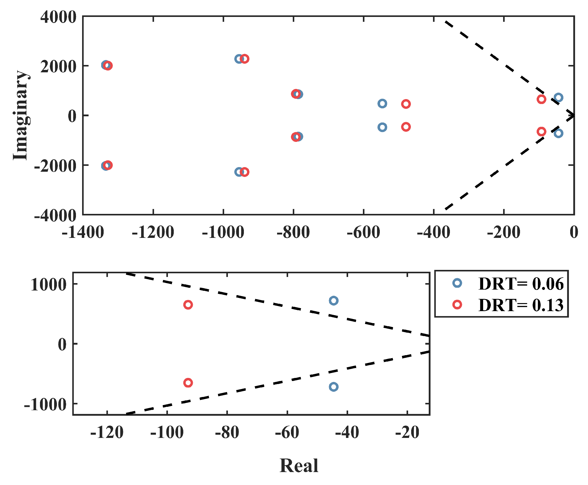
Figure 11,
Figure 12 and
Figure 13 indicate the new eigenvalues of the system after modifying the DRT of the PLL.
As shown in
Figure 11,
Figure 12 and
Figure 13, changing the PLL DRT maintains the small-signal stability margin.
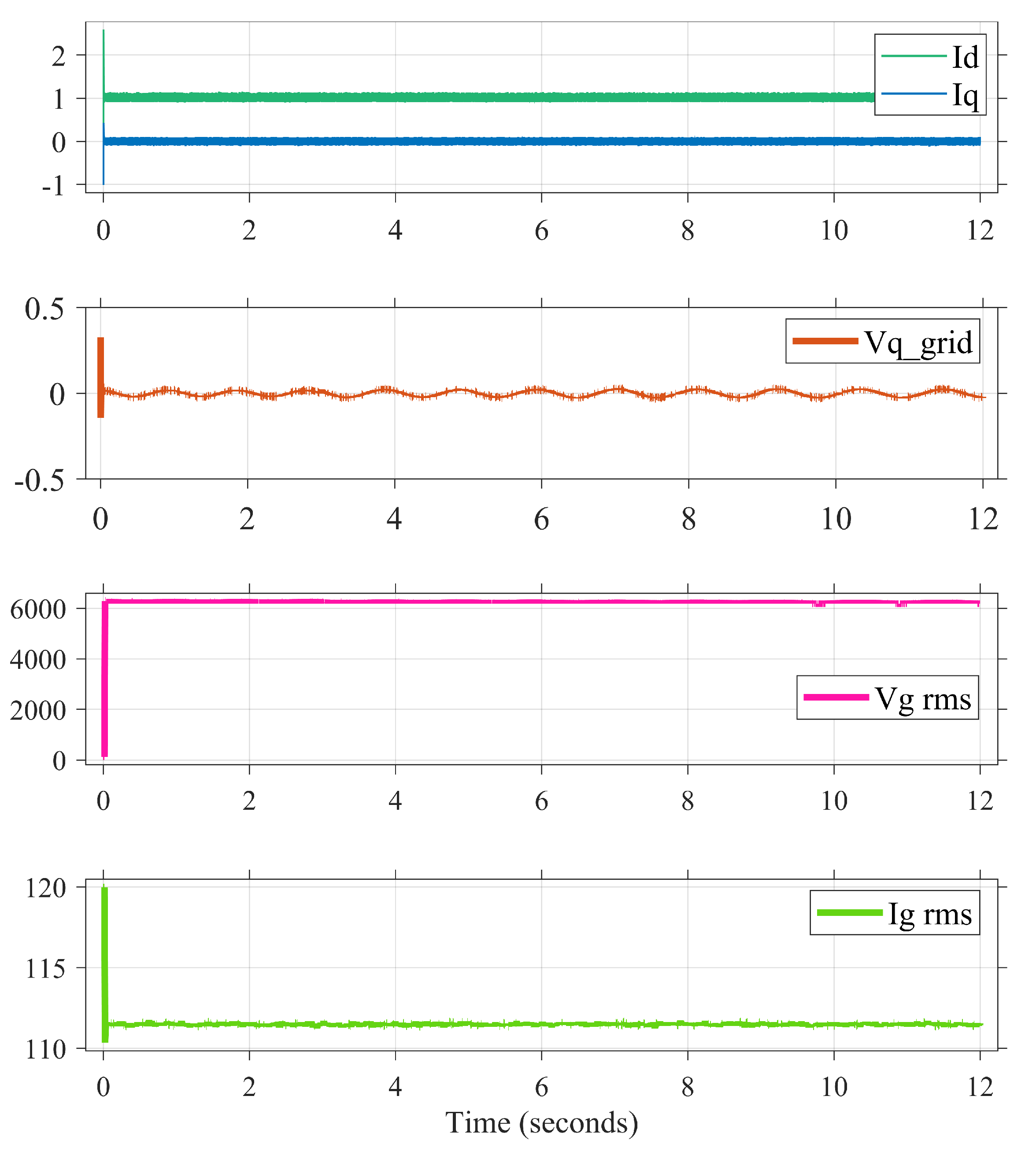
Figure 14 and
Figure 15 indicate the results for the Simulink model.
Figure 14 ensures the system’s stable operation controlled by the proposed algorithm. The simulation scenario is that the system starts at hour 17 with 0.78 p.u. Then, at the second 3, the loading changed to 0.9 (which is the loading condition at hour 18); then, at second 6, the loading is changed to 1 (which is the loading condition at hour 19). Finally, the loading is changed to 0.95 (at hour 20).
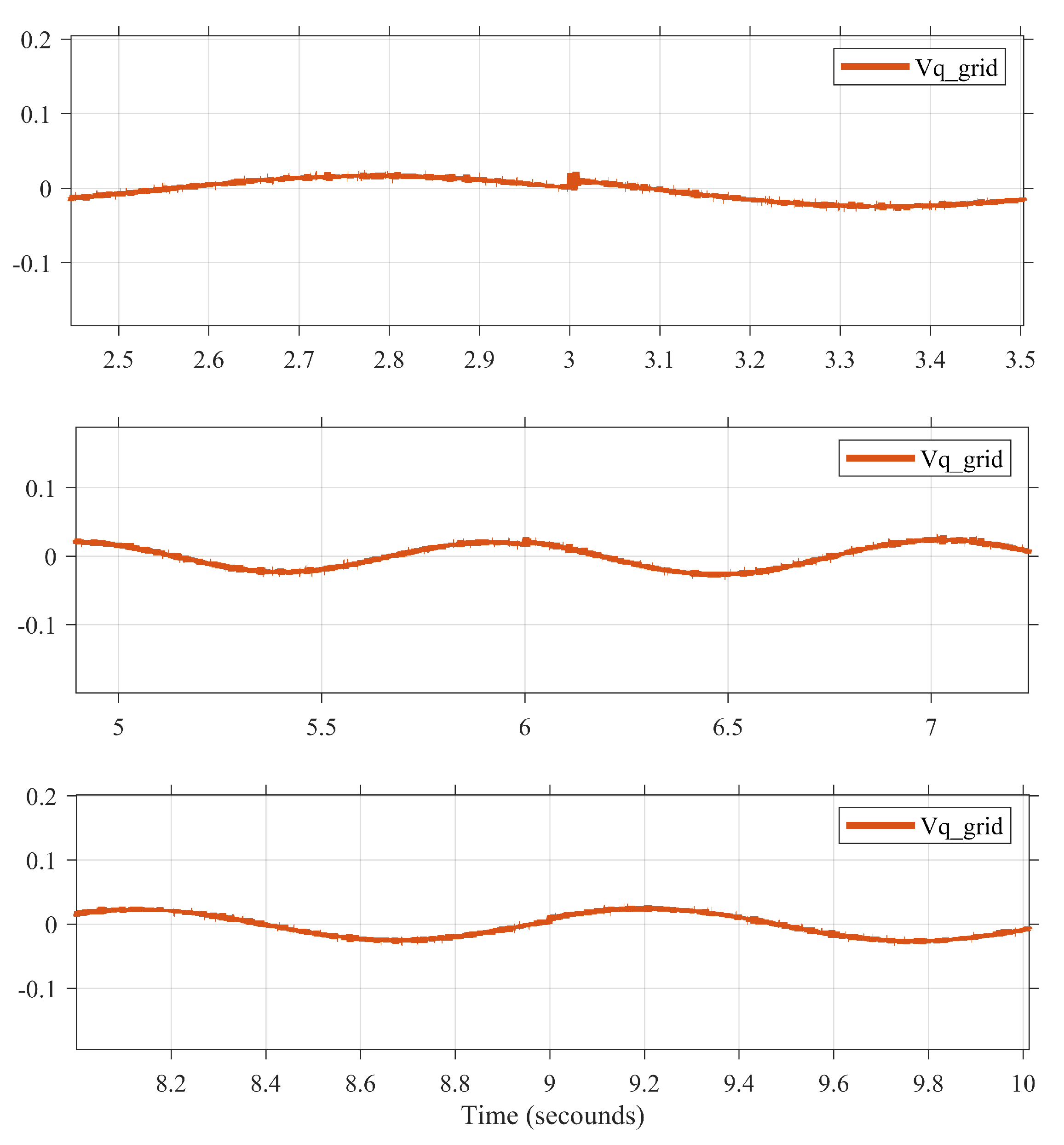
Figure 13 shows the quadrature voltage of the grid (
grid), which indicates the transition moment and ensures the stable operation of the grid. The same result is obtained at other buses in the system. Another note is that the proposed methodology runs faster; consequently, it is more suitable for real-time. The simulation results prove that the proposed methodology has not affected the transient stability but enhanced the small-signal stability.
4.4. System Response When the Algorithm Is the Active and Not Active
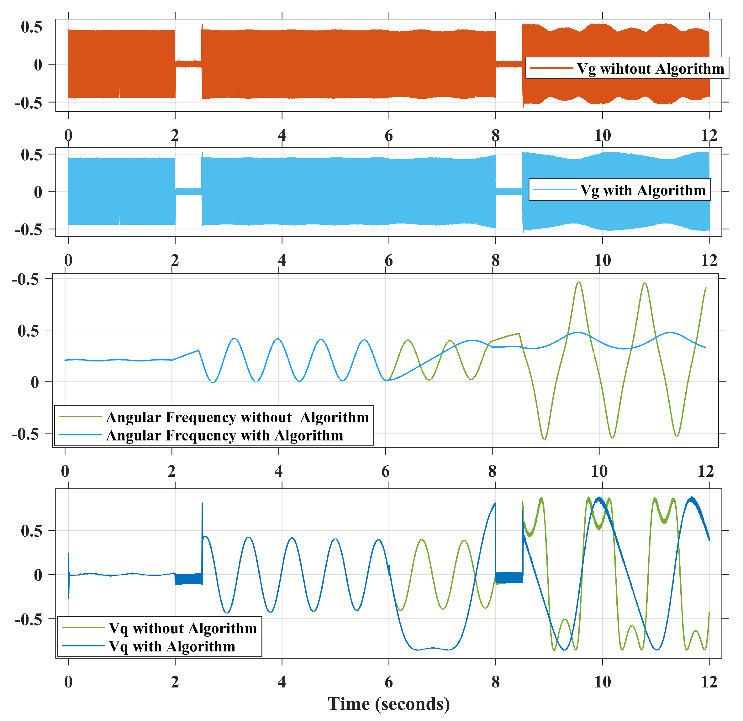
A small scenario is created for this system to test the effect of this algorithm on the system. Two events occur: first, a temporary fault occurs at the 2 s when the system is loaded at 0.42 p.u., which corresponds to hour 1, then there is a transition at 6 s from 0.42 p.u. to 1 p.u., which corresponds to hour 19, and, finally, a minor disturbance occurs at 8 s.
Figure 16 shows the system response when the algorithm is active and when the algorithm is not active; the results prove the ability to decrease the disturbance effect when the algorithm is activated. As shown, the voltage has fewer transition spikes when the algorithm is active, as shown in the second subfigure of
Figure 16. The fourth subgraph indicates the
. In this subfigure, firstly, the system usually starts with
until the fault occurs and is cleared. The average value of the
is zero, but the system has a transition to another loading condition at the sixth second. If the algorithm is activated, the damping constant is modified to suit the new loading condition, causing the
swings around the zero again but with greater amplitude, whereas, if the algorithm is not activated, there is no change, as indicated by the yellow response; when the fault occurs again at the 1 p.u., there are two responses: active algorithm and inactive algorithm. When the algorithm is not active,
oscillated with two spikes instead of one when the algorithm is active. As a result, using the algorithm reduces the number of voltage spices in such a system.
As shown in the third subfigure, using the algorithm reduces oscillation, as indicated by the blue colour, compared to the aggressive behaviour of the system without the algorithm, as indicated by the yellow colour.


