Article

Study on an Ultrasonic Combined Electro-Machining Control System with Composite Material Experiments

1
College of Mechanical Engineering, Yangzhou University, Yangzhou 225127, China
2
College of Hydraulic Science and Engineering, Yangzhou University, Yangzhou 225127, China
3
Advanced Manufacturing and Equipment, Jiangsu Industrial Technology Research Institute, Nanjing 211800, China
*
Author to whom correspondence should be addressed.
Electronics 2022, 11(4), 637; https://doi.org/10.3390/electronics11040637
Submission received: 23 January 2022 / Revised: 11 February 2022 / Accepted: 16 February 2022 / Published: 18 February 2022
(This article belongs to the Section Systems & Control Engineering)

Abstract

:
Materials such as stainless steel, cemented carbide, metal matrix composites, etc., usually require combinations of multiple machining, due to their high hardness, high wear resistance, and other mechanical properties. Ultrasonic combined electro-machining (UCEM) is the preferred solution for the efficient machining of high hardness and high toughness products. However, the machining can deviate from the expected values for factors such as physical and chemical complexity and variability, as well as tool head wear, which can make it difficult to keep the process stable, thus leading to a decrease in machining efficiency. To address the above problems, this study constructed and optimized a UCEM detection and control system based on an analysis of the mutual coordination mechanism of each effects of combined machining, and proposed a machining short-circuit avoidance method based on inter-pulse voltage detection that can avoid the irreversible harm caused by the high current generated during electrode short-circuiting in electrolytic machining. This method could be of great value and significance in preventing workpiece burns and improving machining quality.

1. Introduction

In recent years, with the widespread use of hard and brittle composite materials, the performance requirements of rotary ultrasonic machining equipment have increased [1,2,3]. Although electro-discharged machining (EDM) can machine various kinds of work-pieces, the machining efficiency is low and the accuracy is not satisfying. Electro-chemical machining (ECM) is a non-contact machining method without residual stress or deformation in the material being machined, but electrolytic machining is more complicated in terms of manufacturing cathode tools and has great difficulty in replacing electrolytes due to the difficulty of discharging electrolytic products. Laser beam machining (LBM) is also used as a non-contact machining method, but the surface roughness of the machined workpiece is not good enough with poor dimensional and positioning accuracy; the equipment is also expensive. Ultrasonic machining (USM) can obviously improve the machining efficiency compared with the above mentioned machining methods, but the electrode loss of ultrasonic machining tools is higher, and it is difficult to compensate online. Due to their higher hardness, higher wear resistance and other mechanical proper-ties, stainless steel, cemented carbide, metal matrix composites, etc., usually call for a combination of a variety of machining processes with a single processing method has its advantages and shortcomings [4,5].
UCEM is a hybrid process of rotary ultrasonic machining and electro-machining that can reduce micro-cracks, surface stress and other defects, and is the preferred solution for the efficient machining of high hardness and high toughness products [6,7,8]. In the process of combined electro-machining, the tool electrode vibrates in the axial direction under the action of ultrasonic frequency, the pole is connected to DC or pulse power, the machining area is immersed in working fluid mixed with a certain electrolyte, and the material is removed by ultrasonic combined electric spark or ultrasonic combined electrolysis, or by ultrasonic combined electrochemical discharge machining between the poles.
When a one-dimensional ultrasonic vibration-assisted electrochemical discharge is used to process tiny deep holes in glass [9], copper [10], or titanium alloys [11], vibration at a high or low frequency with a low concentration of electrolytes is able to increase the micro-hole depth and improve the material removal rate [12,13,14].
Natsu found in his experiments on ultrasonic vibration-assisted electrolytic machining that a combined, high frequency ultrasonic vibration was more favorable than a single, low frequency one in terms of material removal rate [15]. Pei modeled the material removal rate of ceramics processed by rotational ultrasonic face milling [16], while some scholars have developed mathematical models of material removal rates for one-dimensional rotational ultrasonic machining based on experiments [17,18].
UCEM organically compounds the vortex, cavitation, and electro-machining in the ultrasonic vibration process to promote the elimination of products from the machining process and the circulation of the working fluid, thus improving the machining efficiency and the machining effect [19]. However, in the UCEM system, the physical and chemical complexity and variability of the machining process, as well as the wear and tear of the tool head in ultrasonic machining and electro-machining, may deviate from the expected values, making it difficult to maintain the stability of the UCEM process, resulting in a decrease in machining efficiency. In particular, when the machining depth and area increase, the ultrasonic vibration parameters and electrical parameters change, and it is often difficult to maintain the efficiency and accuracy of continuous stability, which means that manual intervention is generally difficult to avoid in this situation [20,21,22].
Specifically, throughout the machining control system, research has been conducted based on a short-circuit detection method to solve the short circuit between the tool electrode and the workpiece during machining [23,24], where a short circuit is set between the tool electrode and the workpiece to determine the state of the distance between the tool electrode and the workpiece [25,26]. However, the disadvantage of this method is that only the tool electrode and the workpiece are short-circuited, which is judged by detecting the high current at the time of the short circuit and using this as a signal to back off the electrode by controlling the servo system of the machine [27,28,29,30]. At this point, the ablation caused by the short circuit is already occurring on the contact surface of the tool electrode and the workpiece and causing burns on the electrode and the workpiece; therefore, defects in the application of this method remain. Therefore, proposing new online methods and effectively implementing online inspection of the machining process, as well as avoiding short circuits during machining, are key challenges that must be solved in the area of machining.
To address the above problems, this paper constructed and optimized an UCEM detection and control system based on an analysis of the mutual coordination mechanism of each effect of UCEM, and proposed a machining short-circuit-avoidance method based on inter-pulse voltage detection. This method is based on the phenomenon that the inter-pulse voltage is not zero at the inter-pulse output during UCEM, and determines whether there is a short circuit by detecting the magnitude of the inter-pulse voltage, fundamentally avoiding the irreversible harm caused by a high current that is generated when the electrode is shorted to electrolytic machining.
Through experiments, an analysis of the influence of the control system and the inter-pulse voltage detection method on the machining effect of composite materials is carried out. Combined with real-time detection and an adjustment of the machining system parameters, the ultrasonic and electro-machining action factors are changed to find the optimized parameters of the extreme value point under each condition, in order to keep the machining process continuously stable in real time.

2. Brief Introduction of UCEM System

2.1. Basic Principles of UCEM

In the process of rotating ultrasonic combined electro-machining, metal materials are mainly removed by corrosion using a pulsed electrolytic action, and plastic is removed by abrasive grains (mechanical grinding) using a rotating ultrasonic action, with an occasional electric spark discharge. The reasons for this are mainly the generation of electrolytic hydrogen bubbles and cavitation bubbles in the gap, which reduces the electro-conductivity, while as concerns the local point due to electrolytic passivation, electrolytic removal becomes slower, forming a raised surface point, the gap becomes smaller, and the electrolyte is struck at the point of maximum field strength, forming a tiny spark discharge. This tiny spark discharge is an aid to remove the local difficult machining point, and the amount of material removing is negligible.
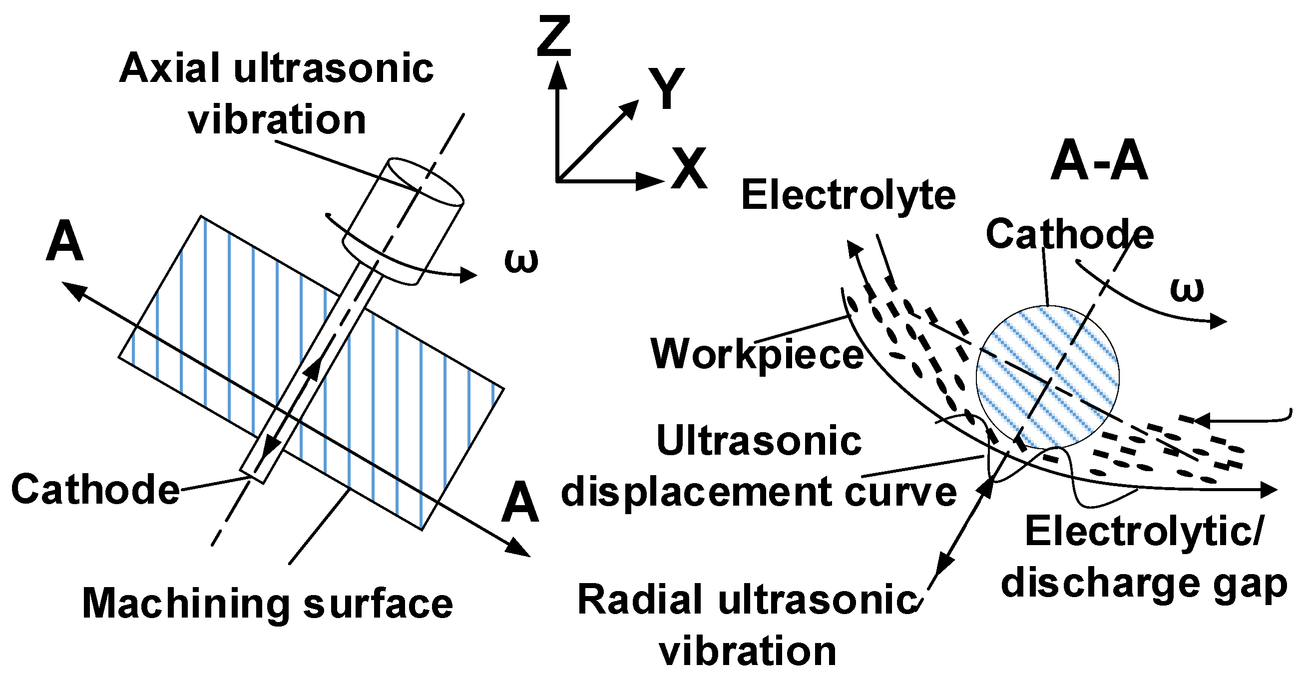
Figure 1 shows the principle diagram of combined electrolytic-discharge spreading machining. When the multi-axis linkage spreading machining surface, the axial Z ultrasonic vibrations and radial X and Y ultrasonic vibrations form a multi-dimensional ultrasonic vibration. During the machining process, due to the ultrasonic vibration in the radial X and Y directions, the electrode gap can be maintained between the tool electrode and the workpiece with reasonable ultrasonic frequency changes can be maintained, which is conducive to strengthening and optimizing the electrolysis-discharge effect between the poles, improving the machining efficiency and stabilizing the machining process at the same time, with better forming accuracy.
Through an analysis of the UCEM, it can be seen that if the machining is destabilized, besides affecting the discharge of machining debris, it is also very likely to cause a short circuit in the electrolytic machining circuit, which would lead to the ablation of the parts and electrodes. To ensure the smooth implementation and steady switching of the above machining, it is necessary to build a multi-energy field synergistic action control system.

2.2. Multi-Energy Coordination Mechanism of UCEM

UCEM integrates three kinds of energy: ultrasonic action, spark discharge action, and electrolytic action. Ultrasonic vibrations are the foundation, and not only have a material removal role in machining, but also promote and improve the role of discharge and electrolytic machining. Discharge and electrolytic machining are the core, and are the most important way to enhance the material removal rate and machining quality of UCEM. This is due to the higher efficiency of discharge and electrolytic machining compared with ultrasonic machining (for conductive materials). 
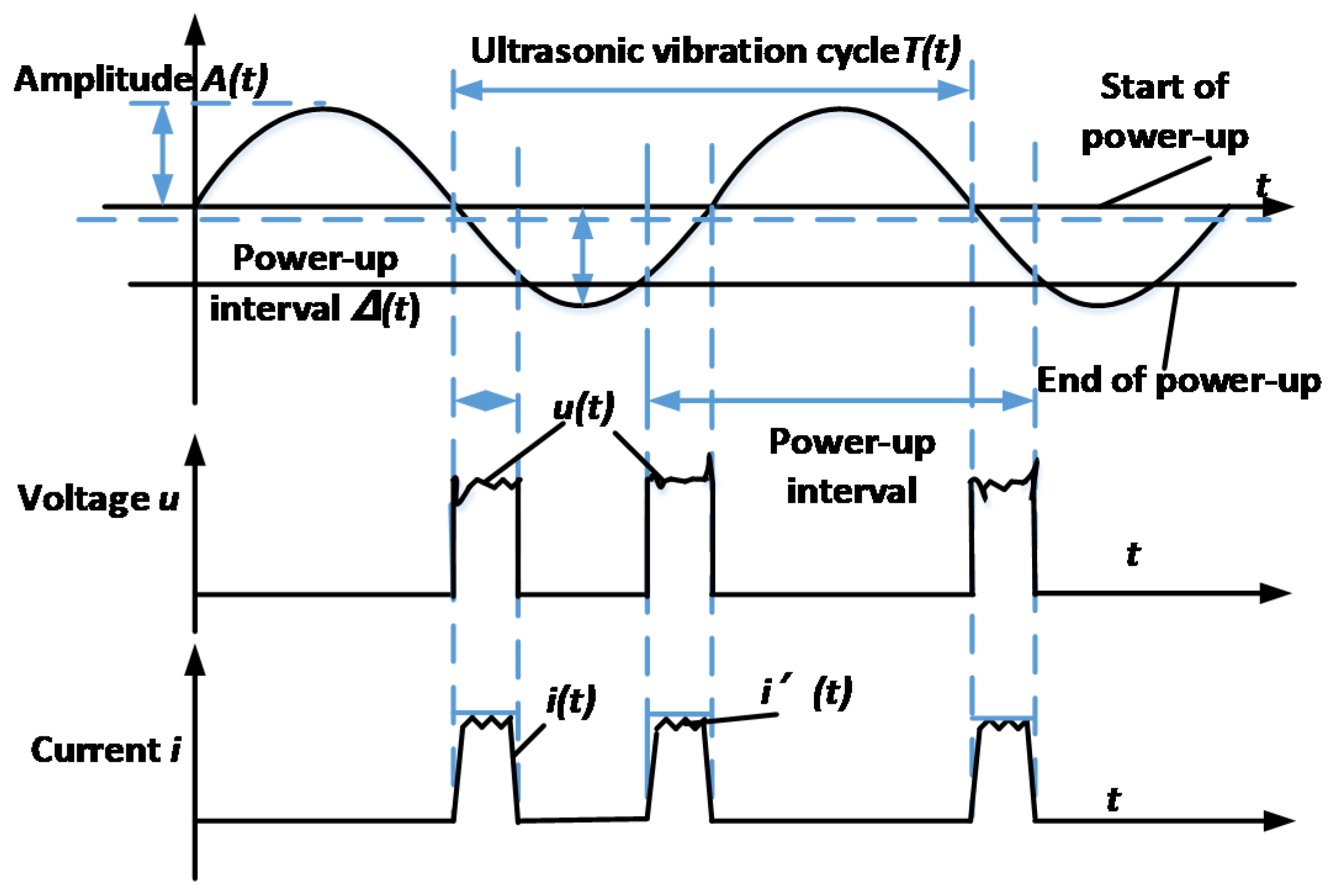
Figure 2 showed the relationship between ultrasonic vibration displacement and interpolar electrical parameters.
Where u ( t ) represents the interpolar voltage, i ( t ) represents the interpolar electrolytic current waveform (corresponding to the low frequency signal of the current waveform), and i ( t ) is the microspark discharge current waveform (corresponding to the high frequency signal of the current waveform), A ( t ) and T ( t ) represent the ultrasonic amplitude and ultrasonic vibration period parameters respectively, and the Δ ( t ) is related to the UCEM gap parameters. All these parameters affect the machining accuracy, efficiency, and process stability. Therefore, it is necessary to change the energy relationship between ultrasonic, electro discharge and electrolytic action by an online adjustment of the machining system parameters in the experiment to find the optimal combination of parameters.
The following is an analysis of the relationship between the energy density of the three actions of ultrasonic, discharge, and electrolysis:
Q u s m ( t ) = 1 / 2 ρ c ( ω A ) 2 u s m [ A ( t ) / T ( t ) ] 2
Q e c m ( t ) e c m u ( t ) i ( t )
Q e d m ( t ) e d m u ( t ) i ( t )
where Q u s m is the ultrasonic energy density, Q e c m is the energy density of electrolytic effect, Q e d m is the energy density of the microspark discharge, and u s m is the coefficient related to working medium density ρ and ultrasonic propagation speed c .
Different detection methods and control strategies should be used for various types of parameters in machining, from one or two effects of the energy relationship, through to testing one, two, or three effects combination tests, and comparisons and analysis of the process and results. For example, when the machining ultrasonic vibrations energy is insufficient for reach the machining requirements, it could be increased by increasing the ultrasonic power supply voltage to improve the ultrasonic frequency; when the electro-machining energy is inadequate for the machining requirements, could be increased by upgrading the pulse power supply voltage, etc. The above examples provide the theoretical basis for designing a control circuit, and constructing and improving the adaptive parameter-seeking system for UCEM.
In rough machining, the maximum etch rate rule is used if machining through holes, where the material removal rate takes precedence and the machining error and surface roughness take second place. If machining a cavity, the conditional maximum material removal rate rule is used, with the machining error taking precedence, and the material removal rate, and surface roughness second. For fine machining, ensuring the final size, shape accuracy, and surface roughness is required under the premise of making the maximum material removal rate and the minimum machining error. In summary, the model adopts the principle of material removal rate maximization, and takes the material removal rate as the objective function, while the surface roughness and machining error are given in the form of constraints.
The surface roughness and machining error are restricted as the index requirements:
R a [ R a ] ,   θ x [ θ x ]
where the square brackets in [ R a ] indicate the permitted value, which is determined according to the machining parameter requirements; [ θ x ] is determined according to the machining-dimensional errors. In addition, the selection of the design variables should be limited by the upper and lower limits of the values taken in compliance with the machining parameters:
t o n min t o n t o n max ,   I m min I m I m max ,   A f min A f A f max ,   V c min V c V c max
The expression of the basic mathematical model of the UCEM is obtained as:
X = [ x 1 , x 2 , x 3 , x 4 , x 5 ] T = [ t o n , t o f f , I m , A f , V c ]
f ( n ) = v m r r max
s . t       R a [ R a ] , θ x [ θ x ]
t o n min t o n t o n max ,   t o f f min t o f f t o f f max ,   I m min I m I m max ,   A f min A f A f max ,   V c min V c V c max
where t o n refers to the pulse width, t o f f refers to the pulse interval, I max refers to peak current, A f refers to the ultrasonic amplitude and V C refers to spindle rotation speed.
Traditional selection methods are not suitable for efficient and high precision control requirements for combined machining processes. Therefore, the key issue is to determine the inputs and outputs of the system as the purpose of designing simple structured controllers in the study of combined machining control systems. For this reason, the artificial neural network technology was introduced into the selection of combined machining parameters, and a neural network-based optimization method was proposed.
From the perspective of network structure, the fewer the number of in-put and output neurons, the easier the adjustment and the higher the accuracy. On the basis of theoretical analysis and experimental studies, the material removal rate, surface roughness, electrode loss rate, machining error, and abrasive number were used as the input parameters of the prediction network; the pulse voltage, electrolyte concentration, feed rate, ultrasonic amplitude, and spindle speed were used as the output quantities of the network. Therefore, a BP neural network structure with five and five neurons in the input and output layers were used to establish the combined machining process model.

2.3. Design of UCEM Control System

The machining system was made up of a rotary ultrasonic unit, an electro-machining unit, a measurement unit, and other modules. The control system controls the subsystems in a unified manner to form a complete machining system. To achieve the machining goal, the parameters of rotary ultrasonic, machining power supply, electrolyte, multi-axis spreading feed, and other links need to be processed online; in particular, the key parameters are real-time adjusted, controlled, and compensated for the fluctuation of other parameters to coordinate the role of ultrasonic, electrolysis, and discharge in UCEM.
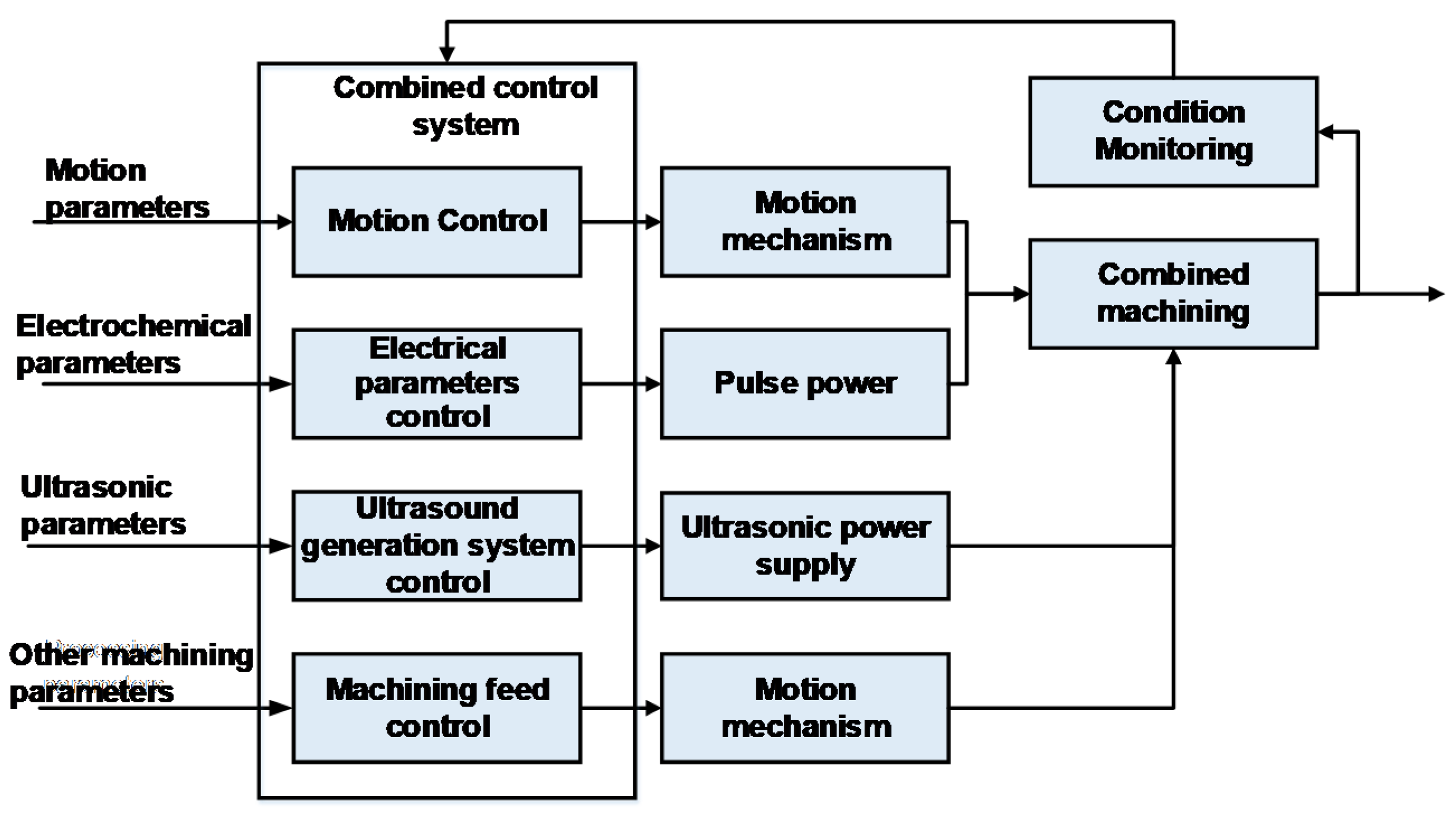
The design control system combined theoretical analysis of the mechanism of multi-effect action and mutual synergy as well as the influence of the machining and its own characteristics, including servo drive control, machining parameter control, pulse power control, ultrasonic parameter control and several other functional modules, as shown in Figure 3.
The overall control scheme of the combined machining system is shown in Figure 4. The computer communicates with the main control core through the serial port to control the rotational motion of the high-speed ultrasonic spindle. The motion control system realizes the table feed motion in all directions and the vertical motion of the rotating ultrasonic spindle. The ultrasonic power supply, pulse power supply and other directional ultrasonic vibration systems are controlled through the main control core. The sensors for acquisition included in the system were pressure, temperature, speed, current, micro-displacement sensors, etc.
The analysis of the mechanism of UCEM and experimental research proved that the machining process is very complex, and the parameters to be selected are not only electro parameters, but also include ultrasonic parameters and other machining parameters and the machining parameters are coupled with each other, whereby the degree of their influence is difficult to quantify. If all the machining parameters are used as the control quantity of the CNC system to form a multi-input multi-output UCEM controller, the controller structure is extremely complicated and difficult to achieve.
To improve the real-time performance of the control system as much as possible and simplify the controller structure and control algorithm, complex process control was achieved by designing multiple single-output fuzzy neural network controllers. The priority decision-maker judged the system fuzzy neural network control strategy to achieve variable structure fuzzy control of the machining process.
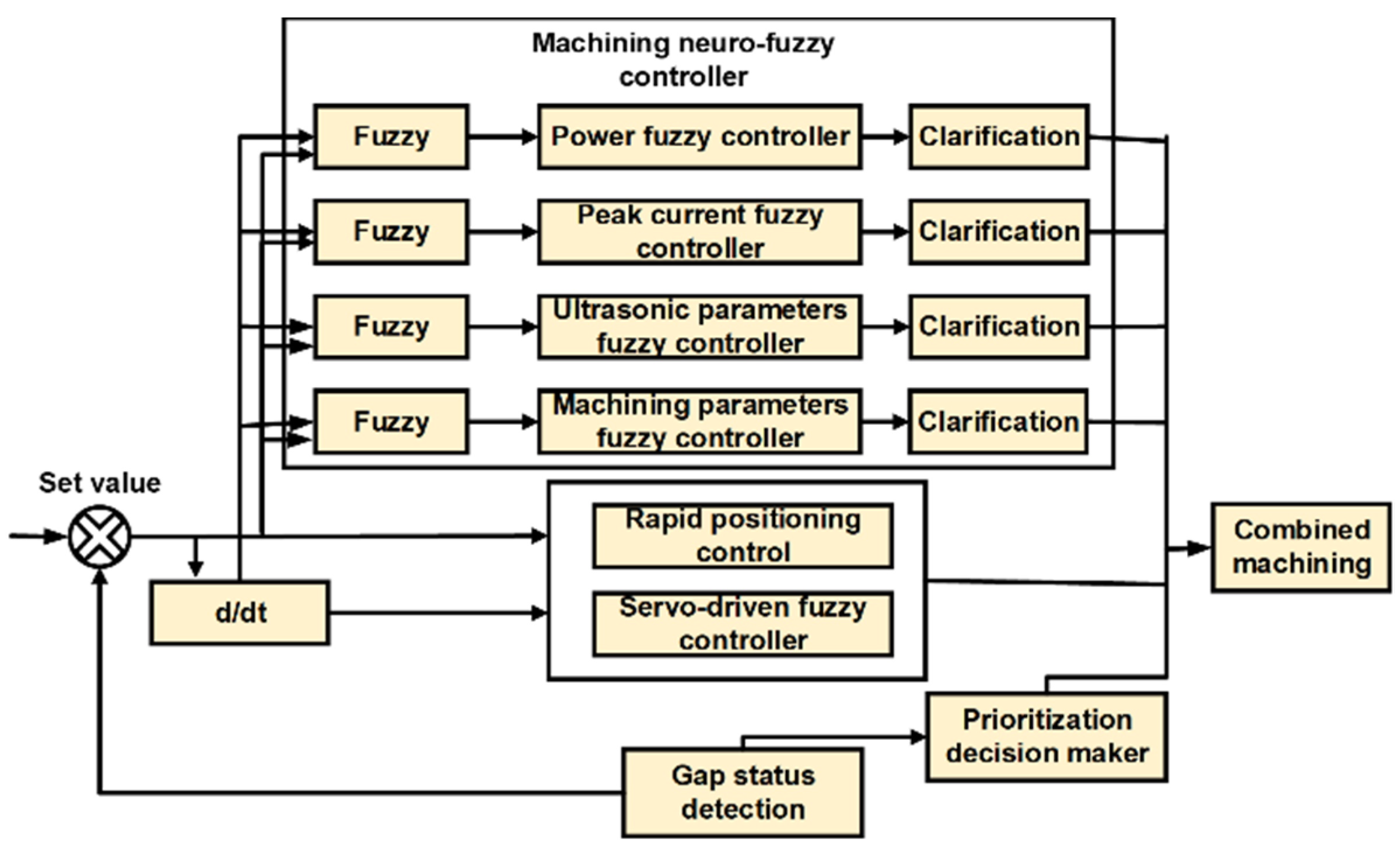
The multi-input with multi-output control system was structurally decomposed to solve the problem of the difficult extraction of control rules for complex multi-input with multi-output systems and the problem of control parameter coupling for complex electro-machining control systems, as well as to achieve uncoupling in the structure. The overall structure of the system controller block diagram is shown in Figure 5.
The system included three parts: the servo-driven fuzzy controller, the parameter adjustment fuzzy controller, and the priority decision controller. By controlling the precise feeding of the servo-feed system to maintain the best discharge gap and avoid unstable machining caused by an unsuitable gap, the parameter controller would achieve online adjustment of the parameters on the basis of machining in an off-line setting, including the parameters that have a greater impact on the stability of the machining, such as pulse interval, peak current, ultrasonic amplitude, and machining parameters.
The control system priority decision-maker has judgment, memory, and machining capabilities. During machining, the priority decision controller makes real-time control decisions in the current machining state through the memory of the current machining state judgment and the previous process decision to adjust the control output; the system constantly detects the correctness of the discharge state judgment decision and constantly corrects the amount of adjustment.
If the current control mode cannot effectively improve the machining state, there is a need to change the control strategy; that is, to adjust to a higher level of control mode for higher priority control or multivariable simultaneous control of the combined control mode, so that the system achieves skilled control effects. Through real-time parameter adjustments to optimize and keep the machining continuously stable, an optimized control scheme can be formed to guide the application and to fulfill the machining requirements of the combined parts.

2.4. Concept of Inter-Pulse Voltage Detection of UCEM

During the machining procedure, if the machining is unstable, it is likely to cause excessive current in the machining circuit in addition to affecting the discharge of machining chips, which would lead to excessive ablation of workpiece and electrodes. To solve this problem, a short circuit avoidance method was used to determine whether a short circuit had occurred. This method was based on the inter-pulse voltage detection by measuring the magnitude of the inter-pulse voltage through taking advantage of the phenomenon that the machining inter-pulse voltage was not be zero in normal state.
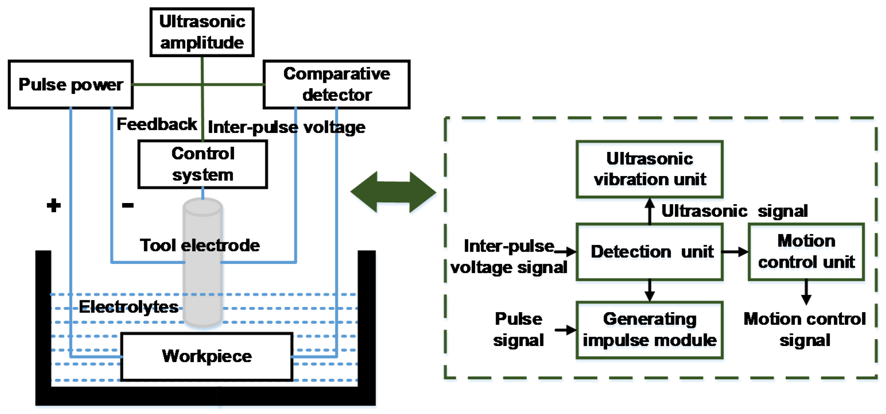
The inter-pulse voltage between the tool electrode and the workpiece was collected and the inter-pulse voltage was introduced to the comparison judge to detect and com-pare at each inter-pulse voltage; furthermore, the judgment signal would be fed back to the pulse power supply system, the ultrasonic generation system, and the machine motion system. Thus, the output of high and low potentials of the pulse power supply, the feed or retraction of the tool electrode and the vibration state of the ultrasonic generator system can be controlled.
The pulse power supply in the study was self-designed and the pulse signal was generated by controlling the MOSFET through the control system. The collection point was set up on each of the tool electrode and the workpiece and the inter-pulse voltage at both ends would be collected into the comparison circuit, and also this input inter-pulse voltage was compared with the reference voltage. The composition of the designed detection module is shown in 
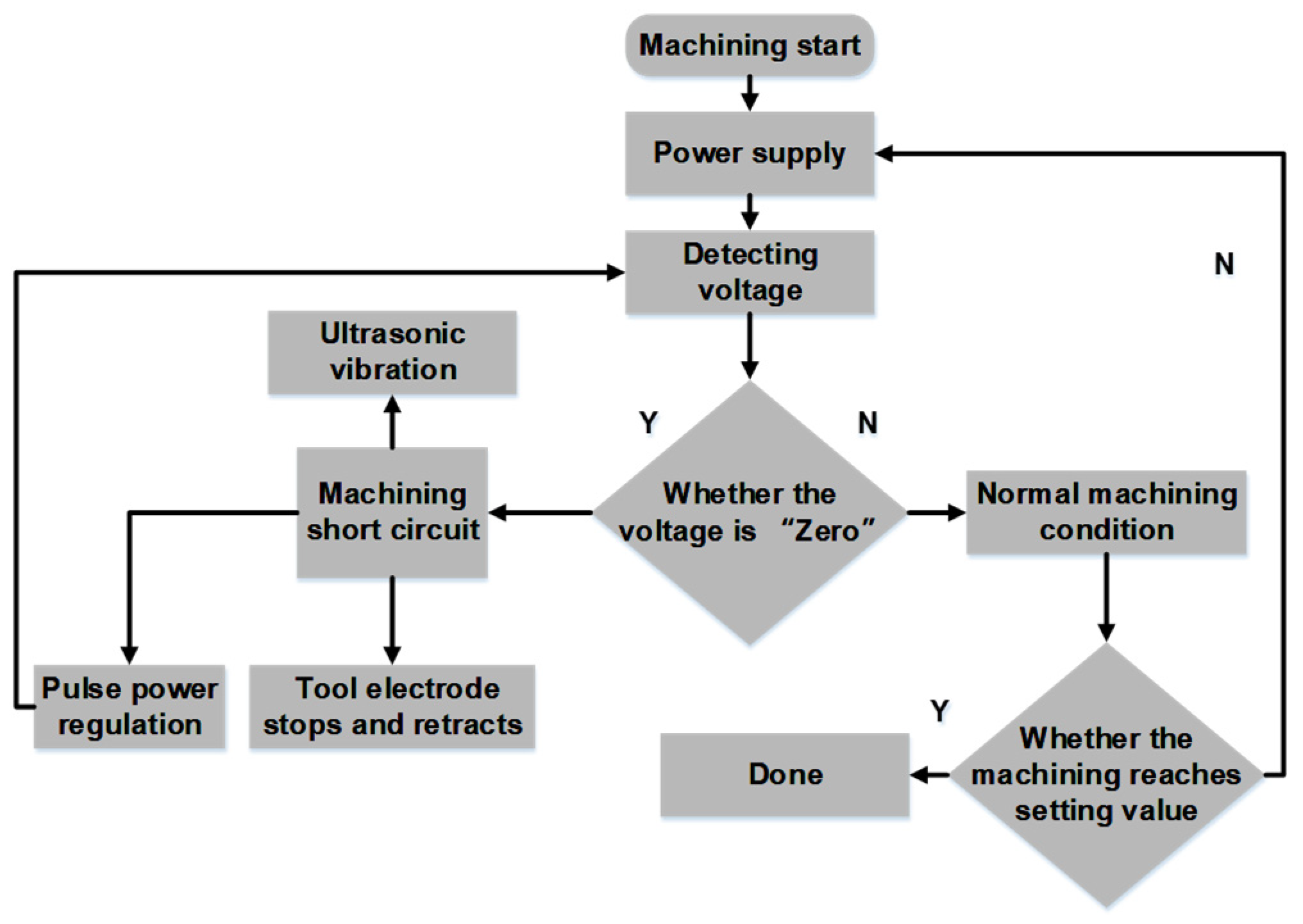
Figure 6. In addition, the flow of detection, feedback, and control during machining as shown in Figure 7.
When the pulse power supply was turned on, in the process of stable machining, the pulse power supply continued to send out nonstop pulse signals, then the comparative judge detected the inter-pulse voltage of this series of signals and made comparative decisions at the same time. If the inter-pulse voltage was not “zero”, the control signal output was normal and the combined machining process would be performed smoothly.
If the inter-pulse voltage value was detected as “zero” suddenly, it can be judged that the tool electrode and the workpiece were in contact due to the fact that the inter-pulse voltage was lower than the reference voltage, also the judgment would send a feedback control signal to determine the short circuit. The feedback signal fed to the control system can make the feeding of the tool electrode stop instantaneously and interrupt the ultrasonic vibration output at the same time, thus avoiding serious collisions between the tool electrode and the workpiece due to continued supply in the case of short circuit. After the machining process was stopped momentarily, the tool electrode is retracted in the opposite direction of the feed direction for short-circuit elimination. Furthermore, the detection and comparison of the inter-pulse were performed all the time during the process. The cycle would be repeated until the detected inter-pulse voltage was not “zero” and the machining system would return to normal.
Through the analysis, it can be known that the output of the comparison circuit acted as the core of the whole machining system which controlled the generation and output of the regulated pulse power supply, the ultrasonic generation system and the machine feed. The comparison voltage set in this study was 0.2 V according to the actual study.

3. Experimental System

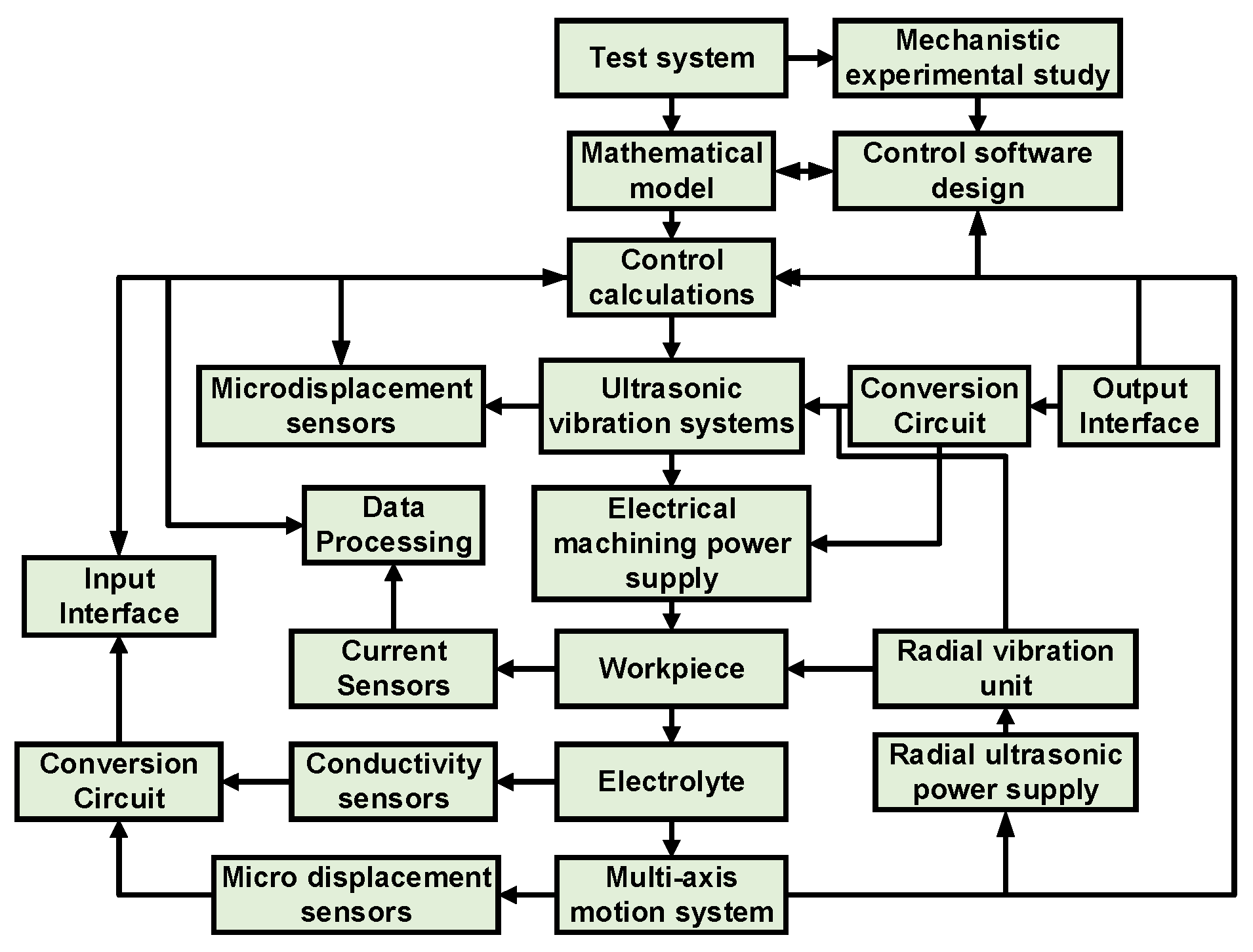
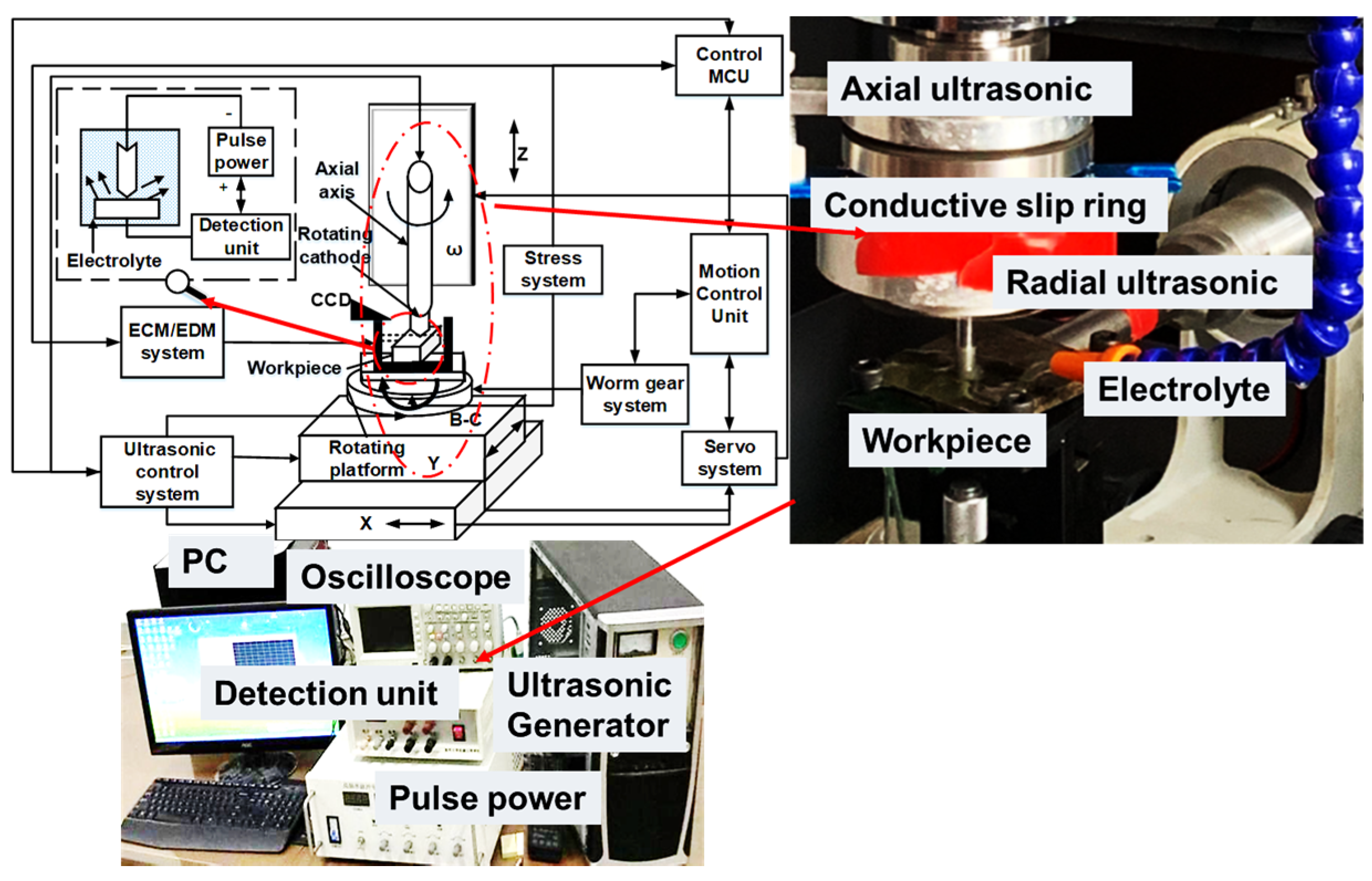
In the previous section, the principle of the UCEM control system and the short-circuit detection of UCEM using the inter-pulse voltage were shown. The experimental system of UCEM system was designed as shown in Figure 8. The computer realized the spatial multi-axis servo feeding of the table and the rotating ultrasonic device through real-time control, and the feeding mechanism was designed with micro-displacement sensors, which can monitor and feedback the spatial position information of the workpiece and electrode in real time.
Through the multi-dimensional ultrasonic control system, the workpiece system resonated and rotated with the normal direction of the machining surface. By modulating the multidimensional rotating ultrasonic parameters, the “electrolysis-discharge” machining was produced between the electrode and the workpiece using the ultrasonic excitation effect, and the “on and off“ of the machining power supply was controlled by the output of the pulse detection module, and the feedback signal was generated by the computer based on the needs of the machining state. The feedback signal was adjusted and controlled in real time by the computer according to the needs of the machining status which could ensure the small gap machining and avoid the machining short-circuit at the same time.
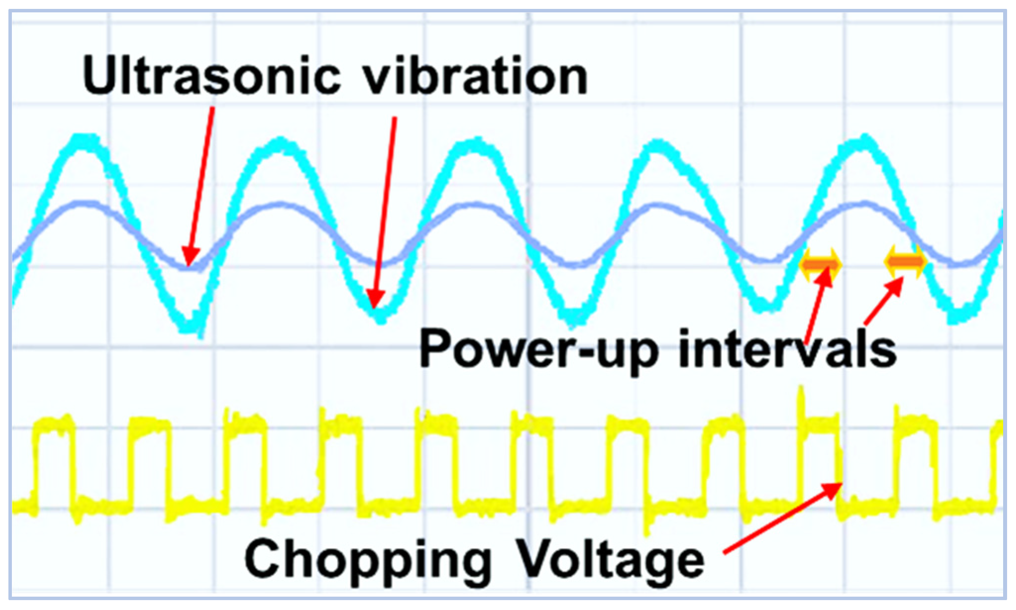
Before conducting the experiment, it was necessary to ensure that the ultrasonic system vibration system was in resonance. The ultrasonic vibration system used in this experiment can realize wide frequency adaptive frequency locking and machining dynamic frequency tracking, its frequency can be automatically adjusted within a certain range, and the control algorithm can adapt to the dynamic load characteristics.
When the ultrasonic vibrations system was in resonance, the vibration displacement curve of the tool electrode was always a similar sinusoidal curve moving up and down with zero reference plane. The waveform of the ultrasonic vibration signal of the actual machining process and the simultaneous combining of the electro discharge machining is shown in Figure 9.

4. Experimental Results and Discussions

What follows are the relevant experimental analyses, mainly for particle-reinforced materials, with comparative experiments designed separately to measure the comprehensive impacts of the designed control system on the machining effect through the experimental results.

4.1. Results of Different Control Methods on Machining Quality

The workpiece material used in this experiment was particle reinforced material, and the tool electrode material was a diamond cemented abrasive tool. Some of the machining parameters are shown in Table 1.
A comparison between manual adjustment and automatic adjustment machining is shown in Figure 10. The manual adjustment machining depth was shallow and the round hole showed a slight deformation. This is because it is difficult to quantify the ultrasonic amplitude, power output, and tool electrode feed during machining, and the machining parameters were determined empirically based on the machining phenomenon observed. By the same token, an electrolytic power supply that is too high or too low can affect machining results. Auto-tuning machining has deeper machining depth and higher circular accuracy. Auto-tuning improved the machining results through real-time detection of machining parameters and feedback adjustments from the control system.

4.2. Influences of Inter-Pulse Detection on Machining Quality

Theoretically, the use of pulse-to-pulse voltage for short circuit detection during machining can aid in avoidance of the short-circuiting of the tool electrode and the surface of the workpiece by high currents during machining, thus improving the machining quality of the workpiece.
To validate that the method can play a role in protecting the short-circuiting in UCEM and can improve the machining quality, two sets of comparison experiments were designed, one of which introduced the pulse voltage short circuit detection to achieve short circuit protection for UCEM, while the other set of experiments did not introduce pulse voltage short-circuit detection. Through a comparison of the experimental results of the two groups, the impact of the pulse voltage short-circuit detection method on the machining accuracy could be determined. The experimental results of the two groups were compared to determine the effect of the inter-voltage-short-circuit detection method on the machining accuracy. The machining parameters of the test are shown in Table 2.
The results in Figure 11 show that machining without short-circuit protection resulted in short-circuiting during machining, which led to chip accumulation on the empty bottom and burn marks, and in severe cases led to machining interruptions. If this happened several times, it would directly affect machining efficiency. In addition, with the short-circuit detection of inter-pulse voltage, it could monitor the occurrence of short-circuiting during machining. It was found that the hole wall was smooth and there were no burn marks. Furthermore, no accumulation of machining debris or ablation craters were found at the bottom, indicating that the machining chip removal and machining were continuous. The machining quality was significantly higher than that without the introduction of short-circuit detection. This is mainly because, during the machining, once the tool electrode and the workpiece were in contact (that is, when the short-circuit occurred in the discharge circuit), the detection signal immediately controlled the output voltage of the pulse power supply, as adjusted the ultrasonic system output, and ordered the servo control system of the tool electrode to realize the retraction, thus avoiding the instantaneous high current due to the short-circuit, eliminating the burn of the workpiece and avoiding the spark discharge between the electrode and the workpiece.

4.3. Discussions of Inter-Pulse Detection on Machining Stability

4.3.1. Effects of Feed Rate on Machining Stability

In the process of machining, in order to discharge the machining debris in time and reduce the occurrence of short circuits in the machining circuit, a smaller feed rate is usually used, thus increasing the input cost of the electrolyte on the one hand and reducing the actual machining efficiency. Using the proposed detection method, when the control system detects a short circuit, it could send a signal to the power supply, ultrasonic, and servo system in time, which can enable the machining continuous and stable machining. Therefore, the impacts of the proposed detection method on the stability of UCEM were illustrated with a comparison between the two cases of increasing the feed rate and detecting a short circuit with and without inter-pulse voltage. The corresponding feed rates of the tool electrodes were 1 mm/min, 2 mm/min, 3 mm/min, and 4 mm/min with the test parameters shown in Table 3.
The experimental results of complex electro-machining without inter-pulse voltage detection at different feed rates are shown in Figure 12. When the feed rate was 1 mm/min, the short circuit occurred after 2.17 mm of machining; when the feed rate was 2 mm/min, the short circuit occurred after 1.89 mm of machining; when the feed rate was 3 mm/min, the short circuit occurred after 1.45 mm of machining, and the machining was forced to stop; when the feed rate increased to 4 mm/min, the short circuit occurred after 0.53 mm of machining, and the machining was forced to stop. From the above, it can be seen that as the feed rate of tool electrode increased, the time interval from the start of machining to the short circuit between the tool electrode and the workpiece was shorter, and the depth of machining was smaller. With short-circuit detection protection, the machining process continued at the same feed rate. Even as the feed rate increased, the entire machining could still be guaranteed, which was completely different from the machining results without detection. The main reason was that when the short circuit occurred, the short-circuit condition of the machining circuit was released in time by power disconnection and tool electrode retractions; thus, continuous machining could be achieved. As can be seen from the above experiments, even as the feed rate increases during machining, the inter-pulse voltage short-circuit detection method is still able to ensure the continuity of the UCEM system effectively.

4.3.2. Effects of Pulse Voltage on Machining Stability

In the UCEM system, the influence of pulse voltage on the machining stability is important, so it is necessary to experimentally analyze the influence of pulse voltage on the machining effect. In this paper, comparative experiments were designed and the machining effect was evaluated using the statistical results of the material removal rate and the surface roughness, and some of the relevant experimental values are listed in Table 4.
Without short-circuit protection, the machining was easily short-circuited under different voltage conditions, leading to a forced stop of the machining. Compared with the situation where the short-circuit detection protection was set at different voltages, the machining process continued. The machining results are shown in Figure 13 and Figure 14. As the machining voltage increased, the machining current density increased, and the workpiece dissolution speed increased, so the material removal rate increased gradually to 1.21 mm3/min. However, the greater the increase in the voltage value, the more serious the stray corrosion phenomenon, leading to a decrease in machining quality, and an increase in electrolytic corrosion energy per unit time, also causing the machining accuracy to decrease by 10%. To obtain a high material removal rate for the composite material, a lower speed, higher voltage, and two-dimensional amplitude should be applied. When the voltage was 7 V, the spark discharge phenomenon occurred several times during the machining, and although the process was not interrupted by a short circuit under the action of the control system, the machining accuracy was obviously reduced, as shown in Figure 15.

4.3.3. Effects of Ultrasonic Amplitude on Machining Stability

According to the theoretical analysis, the ultrasonic amplitude also has a great influence on the machining results. Experimental verification was carried out with the short-circuit detection. As per the previous test, keeping the other conditions unchanged, the voltage was set to 5 V and the axial ultrasonic amplitude was set to 5 μm, 6 μm, 7 μm, and 8 μm, respectively. The results are shown in Figure 16.
The ultrasonic vibration of the tool electrode has a disturbing effect on the electrolyte, which could accelerate the circulation renewal of the electrolyte in the machining gap, thus improving the flow field environment of the machining and increasing the machining efficiency. However, when the amplitude is too large, the electrolytic effect is weakened, which reduces the maximum feed rate of the tool electrode and decreases the machining efficiency, to a certain extent.

4.4. Comparisons of the Prediction Parameter Model in the Machining System

To verify the correctness of the machining process parameter model, experiments with different machining parameters have been conducted on the developed machining system, and the basic machining conditions were consistent with the previous tests. Other parameters are shown in Table 5.
The experimental results in Figure 17 show that the maximum machining surface roughness error obtained by machining using the machining parameters predicted by the system was 8.4%, and the material removal rate error was 12.3%. The test verified that the neural network could reflect the mapping relationship between the parameters and the machining results more correctly. The main reasons for the error between the prediction results and the actual situation were the small number of training samples of the network, and the fact that the simplified part of the model had a small degree of influence and a random influence in the machining process which led to the error between the actual machining results and the prediction results. The experimental results basically confirmed the effectiveness of the established UCEM parameter’s selection model. In addition, the intelligence of the parameter selection meant avoiding a dependence on machining experience and effectively improving the total performance of the machining system with the fault tolerance and associative performance of the BP network. With an increase in machining examples, the neural network would adjust the machining parameter connection weights and thresholds through continuous self-learning, so that it would continuously improve the accuracy of the process knowledge of UCEM and enrich the database with UCEM process knowledge, which could improve the accuracy and realize the intelligence of parameter selection.

5. Conclusions

In this paper, a real-time control scheme for UCEM was proposed based on the construction of the machining system and, in particular, the optimization of the short-circuit detection scheme. According to various experiments, the optimization of the parameters and the controls of the machining process have been carried out, and the machining effect was analyzed and evaluated. This can be summarized as follows:
(1)
We constructed and improved an efficient and stable machining system by analyzing the UCEM component units, thus verifying the correctness and reliability of the design of the UCEM system.
(2)
On the basis of the machining system, a real-time control system for machining testing and feedback was constructed through experimental and theoretical research and parameter optimization to realize the real-time feedback adjustment of machining process parameters.
(3)
When the machining experiments were conducted, by detecting the voltage between the tool electrode and the workpiece between pulses to determine the machining short circuit, the comparison experiments showed that the method of short-circuit determination and control, by detecting the voltage between the pulses, effectively avoided short circuit burns during machining, which could enable continuous and stable machining. Therefore, the machining efficiency was improved.
(4)
Through an analysis of the factors affecting the machining process, a neural network technology was used to establish a neural network-based machining process parameter optimization model. The neural network technology was applied to the machining parameters selection with the machining knowledge was obtained through self-learning of existing data based on a BP neural network structure with five and five neurons in the input and output layers, so that the parameter selection no longer depended on experience. Through experimentations, the machining parameter prediction system have showed that the maximum machining surface roughness error obtained was 8.4% and the material removal rate error was 12.3%.

Author Contributions

Conceptualization, W.C. and J.L.; methodology, W.C.; validation, Y.Z. and J.L.; data curation, W.C.; writing—original draft preparation, W.C.; writing—review and editing J.L.; visualization, Y.Z. and J.Z. All authors have read and agreed to the published version of the manuscript.

Funding

This project was supported by the National Natural Science Foundation of China: 52175438, 51775484, 2021 Jiangsu Province Postgraduate Highlights Study Plan Project: 2021–2022. The authors give cordial thanks to these funding organizations.

Data Availability Statement

The data used to support the findings of this study are included within the article.

Conflicts of Interest

The authors declare no conflict of interest.

References

  1. Inasaki, I. Grinding of Hard and Brittle Materials. CIRP Ann.-Manuf. Technol. 1987, 36, 463–471. [Google Scholar] [CrossRef]
  2. Hao, N.L.; Tian, B.Y.; Li, D.Z.; Wang, H.W. Evaluation of grinding-induced subsurface damage in optical glass BK7. J. Mater. Processing Technol. 2015, 229, 785–794. [Google Scholar]
  3. Wang, Q.; Liang, Z.; Wang, X.; Zhou, T.; Zhao, W.; Wu, Y.; Jiao, L. Investigation on surface formation mechanism in elliptical ultrasonic assisted grinding (EUAG) of monocrystal sapphire based on fractal analysis method. Int. J. Adv. Manuf. Technol. 2016, 87, 2933–2942. [Google Scholar] [CrossRef]
  4. Ding, K.; Fu, Y.; Su, H.; Cui, F.; Li, Q.; Lei, W.; Xu, H. Study on surface/subsurface breakage in ultrasonic assisted grinding of C/SiC composites. Int. J. Adv. Manuf. Technol. 2017, 91, 3095–3105. [Google Scholar] [CrossRef]
  5. Wang, J.; Zhang, J.; Feng, P.; Guo, P. Damage formation and suppression in rotary ultrasonic machining of hard and brittle materials: A critical review. Ceram. Int. 2018, 44, 1227–1239. [Google Scholar] [CrossRef]
  6. Cao, J.; Wu, Y.; Li, J.; Zhang, Q. Study on the material removal process in ultrasonic assisted grinding of SiC ceramics using smooth particle hydrodynamic (SPH) method. Int. J. Adv. Manuf. Technol. 2016, 83, 985–994. [Google Scholar] [CrossRef]
  7. Zhou, H.; Zhang, J.; Yu, D.; Feng, P.; Cai, W. Advances in rotary ultrasonic machining system for hard and brittle materials. Adv. Mech. Eng. 2019, 11, 1687814019895929. [Google Scholar] [CrossRef]
  8. Zhang, X.; Yang, L.; Wang, Y.; Lin, B.; Shi, C. Mechanism study on ultrasonic vibration assisted face grinding of hard and brittle materials. J. Manuf. Processes 2020, 50, 520–527. [Google Scholar] [CrossRef]
  9. Razfar, M.R.; Behroozfar, A.; Ni, J. Study of the effects of tool longitudinal oscillation on the machining speed of electrochemical discharge drilling of glass. Precis. Eng. 2014, 38, 885–892. [Google Scholar] [CrossRef]
  10. Bhattacharyya, B.; Malapati, M.; Munda, J.; Sarkar, A. Influence of tool vibration on machining performance in electrochemical micro-machining of copper. Int. J. Mach. Tools Manuf. 2007, 47, 335–342. [Google Scholar] [CrossRef]
  11. Basavaraju, H.R.; Suresh, R.; Manjunath, S.S.; Janardhan, L. Study on effect of process parameters on MRR and surface roughness in wire electrical discharge machining of titanium grade 7 alloy. Mater. Today Proc. 2021, 47, 2481–2485. [Google Scholar] [CrossRef]
  12. Elhami, S.; Razfar, M.R. Analytical and experimental study on the integration of ultrasonically vibrated tool into the micro electro-chemical discharge drilling. Precis. Eng. 2017, 47, 424–433. [Google Scholar] [CrossRef]
  13. Wüthrich, R.; Hof, L.A. The gas film in spark assisted chemical engraving (SACE)—A key element for micro-machining applications. Int. J. Mach. Tools Manuf. 2006, 46, 828–835. [Google Scholar] [CrossRef]
  14. Ghoshal, B.; Bhattacharyya, B. Influence of vibration on micro-tool fabrication by electrochemical machining. Int. J. Mach. Tools Manuf. 2013, 64, 49–59. [Google Scholar] [CrossRef]
  15. Natsu, W.; Nakayama, H.; Yu, Z. Improvement of ECM characteristics by applying ultrasonic vibration. Int. J. Precis. Eng. Manuf. 2012, 13, 1131–1136. [Google Scholar] [CrossRef]
  16. Pei, Z.J.; Ferreira, P.M. An experimental investigation of rotary ultrasonic face milling. Int. J. Mach. Tools Manuf. 1999, 39, 1327–1344. [Google Scholar] [CrossRef]
  17. Singh, R.P.; Singhal, S. Investigation of machining characteristics in rotary ultrasonic machining of alumina ceramic. Mater. Manuf. Processes 2016, 32, 309–326. [Google Scholar] [CrossRef]
  18. Jadhav, D.B.; Jadhav, P.V.; Bilgi, D.S.; Sawant, A.A. Experimental Investigation of MRR on Inconel 600 using Ultrasonic Assisted Pulse Electrochemical Machining. IOP Conf. Ser. Mater. Sci. Eng. 2018, 377, 12095. [Google Scholar] [CrossRef]
  19. Zhao, Q.; Deng, Z.; Yang, D.; Gu, X.; Zhu, Y. Study on Multi-effect Synergy Mechanism of the Ultrasonic Compound Electro-discharged and Electrochemical Machining and Real Time Optimal Controlling of On-line Parameters. Procedia CIRP 2018, 68, 150–155. [Google Scholar] [CrossRef]
  20. Schubert, A.; Zeidler, H.; Osch?Tzchen, M.H.; Schneider, J.; Hahn, M. Enhancing Micro-EDM using Ultrasonic Vibration and Approaches for Machining of Nonconducting Ceramics. J. Mech. Eng. 2013, 59, 156–164. [Google Scholar] [CrossRef]
  21. Deng, Z.Q.; Zhu, Y.W.; Wang, F.; Gu, X.; Yang, D. Analysis and Experimental Study of Vibration System Characteristics of Ultrasonic Compound Electrical Machining. Strength Mater. 2017, 49, 37–44. [Google Scholar] [CrossRef]
  22. Kozak, J.; Rajurkar, K.P.; Makkar, Y. Selected problems of micro electrochemical machining. J. Mater. Processing Technol. 2015, 149, 426–431. [Google Scholar] [CrossRef]
  23. Elhami, S.; Razfar, M.R. Effect of ultrasonic vibration on the single discharge of electrochemical discharge machining. Mater. Manuf. Processes 2018, 33, 444–451. [Google Scholar] [CrossRef]
  24. Jain, A.; Singh, G.; Jain, V.; Gupta, D. Feasibility analysis for machining serpentine microchannels on glass using rotary ultrasonic milling. Measurement 2020, 160, 107844. [Google Scholar] [CrossRef]
  25. Ghoshal, B.; Bhattacharyya, B. Vibration assisted electrochemical micromachining of high aspect ratio micro features. Precis. Eng. 2015, 42, 231–241. [Google Scholar] [CrossRef]
  26. Barman, S.; Hanumaiah, N.; Puri, A.B. Investigation on shape, size, surface quality and elemental characterization of high aspect-ratio blind micro holes in die sinking micro EDM. Int. J. Adv. Manuf. Technol. 2015, 76, 115–126. [Google Scholar] [CrossRef]
  27. Ghoshal, B.; Bhattacharyya, B. Shape control in micro borehole generation by EMM with the assistance of vibration of tool. Precis. Eng. 2014, 38, 127–137. [Google Scholar] [CrossRef]
  28. Liu, D.; Cong, W.L.; Pei, Z.J.; Tang, Y. A cutting force model for rotary ultrasonic machining of brittle materials. Int. J. Mach. Tools Manuf. 2012, 52, 77–84. [Google Scholar] [CrossRef] [Green Version]
  29. Wang, J.; Zhang, J.; Feng, P.; Guo, P. Experimental and theoretical investigation on critical cutting force in rotary ultrasonic drilling of brittle materials and composites. Experimental and theoretical investigation on critical cutting force in rotary ultrasonic drilling of brittle materials and composites. Int. J. Mech. Sci. 2018, 135, 555–564. [Google Scholar]
  30. Skoczypiec, S. The role of unconventional manufacturing processes in modern manufacturing chain. Innowacje Zarządzaniu Inżynierii Produkcji 2017, 14, 815–826. [Google Scholar]
Figure 1. Mechanism of multi-dimensional rotational ultrasonic combined electrochemical formation machining.
Electronics 11 00637 g001
Figure 2. Schematic diagram of the multi-energy effect of UCEM.
Electronics 11 00637 g002
Figure 3. Functional block diagram of combined machining system.
Electronics 11 00637 g003
Figure 4. Schematic of the control system.
Electronics 11 00637 g004
Figure 5. Machining controller structure block diagram.
Electronics 11 00637 g005
Figure 6. Schematic diagram of inter-pulse detection and control system.
Electronics 11 00637 g006
Figure 7. Detection, feedback, and control flowchart.
Electronics 11 00637 g007
Figure 8. Overview of the Machining system.
Electronics 11 00637 g008
Figure 9. Ultrasonic frequency vibration synchronous pulse voltage diagram.
Electronics 11 00637 g009
Figure 10. Effect of different control systems on machining results: (a) manual control; (b) auto-tuning control.
Electronics 11 00637 g010
Figure 11. Effects of with/without short-circuit detection on machining: (a) without short-circuit detection; (b) with short-circuit detection.
Electronics 11 00637 g011
Figure 12. Short-circuit machining depth at different feed rates.
Electronics 11 00637 g012
Figure 13. Resulting morphology for different feed rate voltage: (a) 3 V; (b) 4 V; (c) 5 V; (d) 6 V.
Electronics 11 00637 g013
Figure 14. Roughness and material removal rate results of different specimens under different voltage: (a) roughness results; (b) material removal rate results.
Electronics 11 00637 g014
Figure 15. Resulting morphology of the damaged workpiece.
Electronics 11 00637 g015
Figure 16. Roughness and material removal rate results of different specimens under different ultrasonic amplitudes: (a) roughness results; (b) material removal rate results.
Electronics 11 00637 g016
Figure 17. Machining results of predicted versus experimental values: (a) surface roughness of different specimens; (b) material removal rate results of different specimens.
Electronics 11 00637 g017
Table 1. Same machining parameters under different control methods.
ItemsParameters
workpiecesSiCp/Al, 55%
tool electrodesdiamond, diameter, 6 mm, grain density, 400 mesh
pulse voltageduty cycle, 50%; voltage, 5 V
ultrasonic amplitudeaxial ultrasonic amplitude, 7 μm;
radial ultrasonic amplitude, 4 μm
feed rate2 mm/min
spindle speed2000 r/min
electrolyteNaCl, mass fraction, 7%
Table 2. Machining parameters with and without detection unit.
ItemsParameters
workpiecesSiCp/Al, 55%
tool electrodesdiamond, diameter, 6 mm, grain density, 400 mesh
pulse voltageduty cycle, 50%; voltage, 5 V
ultrasonic amplitudeaxial ultrasonic amplitude, 7 μm;
radial ultrasonic amplitude, 4 μm
feed rate2 mm/min
spindle speed2000 r/min
electrolyteNaCl, mass fraction, 7%
Table 3. Machining parameters with different feed rate.
ItemsParameters
workpiecesSiCp/Al, 55%
tool electrodesdiamond, diameter, 6 mm, grain density, 400 mesh
pulse voltageduty cycle, 50%; voltage, 5 V
ultrasonic amplitudeaxial ultrasonic amplitude, 7 μm;
radial ultrasonic amplitude, 4 μm
feed rate1 mm/min, 2 mm/min, 3 mm/min, 4 mm/min
spindle speed2000 r/min
electrolyteNaCl, mass fraction, 7%
Table 4. Different pulse voltage machining parameters.
ItemsParameters
workpiecesSiCp/Al, 55%
tool electrodesdiamond, diameter, 6 mm, grain density, 400 mesh
pulse voltageduty cycle, 50%; voltage, 3 V, 4 V, 5 V, 6 V
ultrasonic amplitudeaxial ultrasonic amplitude, 7 μm;
radial ultrasonic amplitude, 4 μm
feed rate3 mm/min
spindle speed2000 r/min
electrolyteNaCl, mass fraction, 7%
Table 5. Prediction parameters model machining parameters.
ItemsPulse Voltage
(V)
Ultrasonic Amplitude
(μm)
Feed Rate
(mm/min)
Spindle Speed
(r/min)
No.
3732000
5621000
5541500
4713000
Publisher’s Note: MDPI stays neutral with regard to jurisdictional claims in published maps and institutional affiliations.

