Article

Design of a High-Durability X-Band Patch Antenna with a CPW Feeding Network Based on a Durability Evaluation Analysis

1
School of Electronic and Electrical Engineering, Hongik University, Seoul 04066, Korea
2
LIG Nex One Radar Research Institute, Yongin 16911, Korea
3
Department of Electrical, Electronic, and Communication Engineering, Hangyang Cyber University, Seoul 04066, Korea
*
Author to whom correspondence should be addressed.
Electronics 2022, 11(4), 553; https://doi.org/10.3390/electronics11040553
Submission received: 14 January 2022 / Revised: 3 February 2022 / Accepted: 7 February 2022 / Published: 12 February 2022

Abstract

:
In this paper, we propose a high-durability X-band patch antenna with a coplanar waveguide (CPW) feeding network that can directly connect the upper antenna and the lower transmitting receiver modules without additional cabling. To improve the durability of the antenna, both the sub miniature push-on (SMP) connector and the feed-pin are separated through the CPW layer. This separated structure can minimize the deterioration of the antenna performance when the unwanted movement of the SMP connector occurs from external shocks. To verify the design feasibility, the reflection coefficient and radiation patterns of the proposed antenna are measured in a full anechoic chamber. The reflection coefficient of the proposed antenna is −27 dB at 10 GHz, and the operating frequency bandwidth (|Γ| < −10 dB) is 4.7% (9.82~10.29 GHz) in X-band. The proposed antenna has a maximum gain of 5.7 dBi at the bore-sight direction. In addition, the durability evaluations of the proposed design according to unwanted SMP connector movements provoked by external shocks are investigated using Monte Carlo simulations. The results demonstrate that the proposed high-durability antenna design is suitable for military ship applications that involve exposure to various external shocks.

1. Introduction

In recent years, there has been an increasing demand for the use of X-band array antennas in military ship radar systems for detecting targets, navigation, and safety [1,2,3,4]. In such radar systems, because ships are frequently damaged by various external shocks, the antenna element of the radar must be designed to be structurally stable. In previous studies, various individual element types for X-band radar systems have been reported, such as Vivaldi antennas [5,6], dipole antennas [7,8,9], and horn antennas [10,11]. In particular, patch-type antennas with a low profile and reduced radar cross-section characteristics are considered to be more suitable for military ship radar systems [12,13,14]. In this application, the patch array antennas are typically connected to transmitting receiver modules (TRMs) for steering the array beam. Herein, antenna elements usually use various transmission lines such as microstrip [15], substrate integrated waveguide (SIW) [16], and coplanar waveguide (CPW) [17,18,19] to connect the antenna and TRM. In this research, although some antennas have a high gain, the size of the antenna is bulky considering the operating frequency [15,16,19]. On the other hand, other antennas have a small size with proper antenna gain [17,18]. However, in these antennas, frequent external shocks at the connection part between the antenna and the TRM can easily accumulate structural fatigue, which may cause fatal defects in electromagnetic power transmission from the TRMs to the antenna. To improve antenna durability, structurally stable shapes (e.g., using support posts or a metallic body, etc.) have been applied to the design of the antenna element [20,21]. In some cases, dielectric substrates that strongly resist physical impact have also been employed [22]. In general, because high heat is typically generated during radar operation, using a solder with a high melting point would be a good solution to enhance durability [23]. More recently, in some design cases, sub miniature push-on (SMP) connectors mounted on the bottom surface of the antenna layer, are required to directly connect both the antenna and the TRM without complicated cabling [24]. However, when applying these techniques to the antenna, there is not in-depth consideration for improving the durability of the connection part that is relatively weak against external shocks.
In this paper, we propose a high-durability X-band patch antenna with a coplanar waveguide (CPW) feeding network that can directly connect the upper antenna and the lower TRM without additional cabling. To improve the durability of the antenna, both the SMP connector and the feed-pin are separated through the CPW layer, so that when unwanted feed-pin movement occurs due to external shocks, the deterioration of the antenna performance can be minimized. The line width of the CPW near the feed-pin is designed to be sufficiently thick, whereas a narrow line width is needed near the SMP connector. Thus, the proposed CPW layer requires a transition part that can maintain impedance matching characteristics between the thick line for the feed-pin and the thin line for the SMP connector. To verify the high durability of the design, the proposed antenna with the CPW layer is fabricated, and its antenna performances such as reflection coefficient and radiation patterns are measured in a full anechoic chamber. Finally, to more accurately evaluate the durability of the design, performance degradations due to unwanted SMP connector movements provoked by external shocks are investigated using Monte Carlo simulations. From this durability evaluation of the proposed antenna, the results demonstrate that the proposed antenna has a high durability through CPW feeding network that can play the interface between the antenna and TRM. Thus, this antenna design is suitable for military ship applications that involve exposure to various external shocks.

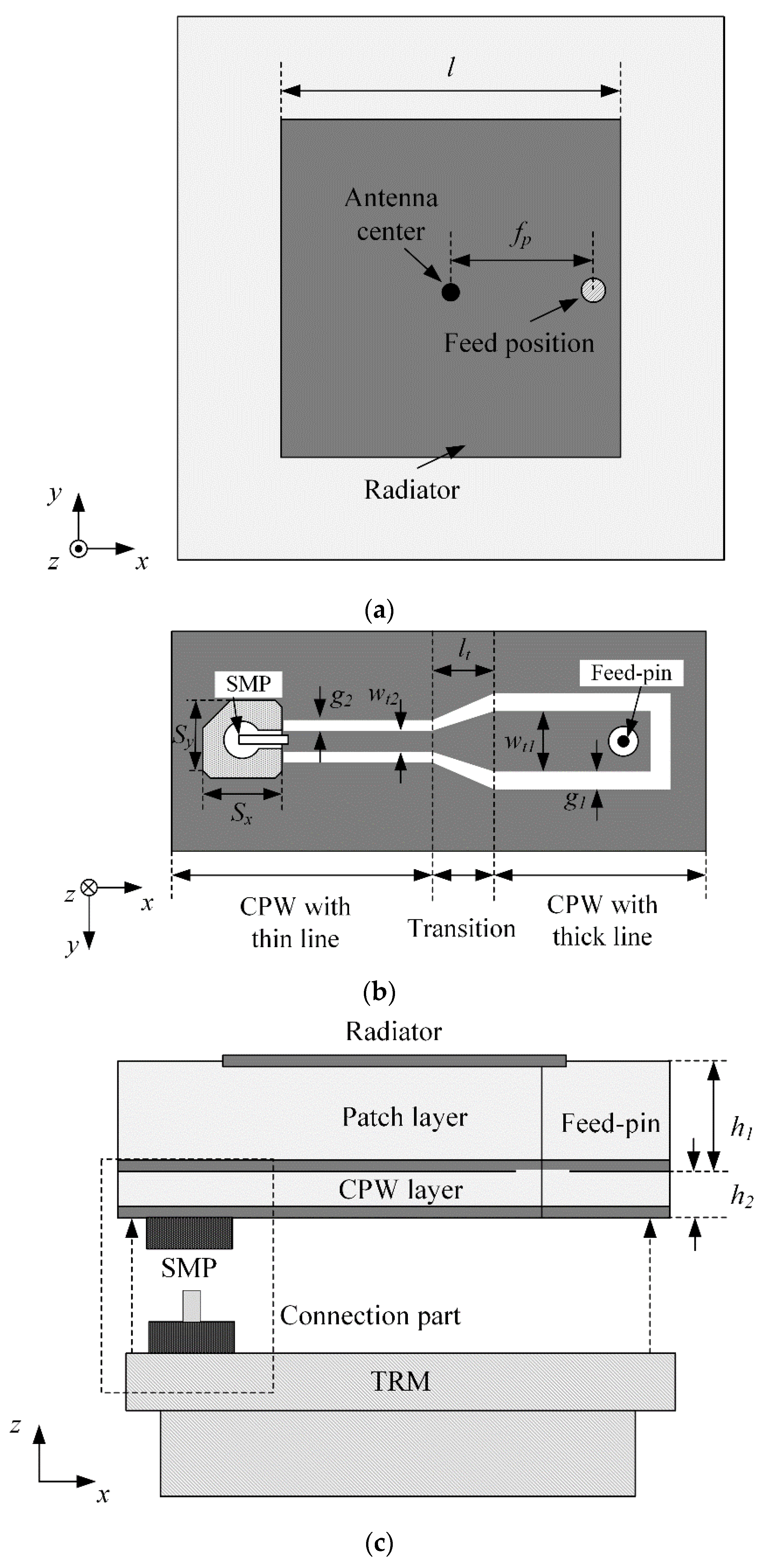
2. Proposed Antenna Design

Figure 1 presents the geometry of a high-durability X-band patch antenna with a CPW feeding network that can directly connect the upper antenna and the lower TRM without additional cabling. The square patch antenna has a length of l, and the feed-pin has an offset position fp from the antenna center along the x-axis, as shown in Figure 1a. To improve the durability of the antenna, both the SMP connector with size of Sx × Sy and the feed-pin are separated through the CPW layer. Through this design technique, the deterioration of antenna performance can be minimized when unwanted feed-pin movement occurs due to external shocks. Thus, the line width (wt1) and gap (g1) of the CPW near the feed-pin are designed to have a sufficiently wide line width because the feed-pin must be stably connected to the CPW line by soldering. For example, if the line width of the CPW near the feed-pin is not wide enough, the soldering connection between the CPW and the feed-pin can be easily damaged by external shocks. On the other hand, it is recommended that the X-band radar have a small SMP connector in general [24,25] to minimize physical interference between neighboring elements when antenna elements are expanded to a full array. Due to the small entrance size of the SMP connector, a narrow line width of wt2 and a gap of g2 are applied to the CPW structure near the SMP connector. Thus, because the line width of both ends of the CPW is not the same, the proposed CPW layer requires a transition part with a length of lt, as shown in Figure 1b. This transition part can maintain impedance matching characteristics between the thick line for the feed-pin and the thin line for the SMP connector. Using the CPW feeding network, the patch antenna located at the top is directly connected to the bottom TRM, and the resulting absence of complicated cabling makes system maintenance much easier. The proposed antenna combines both a patch layer and a CPW layer as shown Figure 1c. The conducting patch is printed on a TLY-5 substrate (εr = 2.2, tan δ = 0.0009) with a height of h1, and an FR-4 substrate (εr = 4.5, tan δ = 0.016) with a height of h2 is used for the CPW feeding network. The proposed antenna is modeled using the FEKO full electromagnetic simulator [26], and the detailed design parameters are listed in Table 1.
Figure 2 illustrates a photograph of the fabricated high-durability antenna. The patch layer and the CPW layer are strongly adhered through a bonding film, and a thin cylindrical conductor pin is inserted between the radiator and the CPW line. Due to the thick line width of the CPW line near the feed-pin, the patch antenna pattern at the top layer and the CPW line at the bottom layer can be firmly connected by soldering. The SMP connector [25] is precisely mounted on the CPW layer that is coated except for the direct installation part. This configuration can directly connect to the TRM without the complicated cabling. To verify the antenna feasibility, the reflection coefficient and radiation pattern are measured in a full EM anechoic chamber.
Figure 3 shows the measured (solid line) and simulated (dashed line) reflection coefficients of the proposed antenna. The measured reflection coefficient is observed to be −27 dB at 10 GHz, which is in good agreement with the simulated result of −20.9 dB. In addition, the measured fractional bandwidth (|Γ| < −10 dB) is 4.7% (9.82~10.29 GHz), and that of the simulation is 3.3% (9.84~10.17 GHz). Thus, the proposed antenna can be applied to the X-band radar applications.
Figure 4 presents the 2D radiation patterns of the zx-plane (E-plane) by measurement and simulation. In the bore-sight direction, the measured and simulated gains are 5.8 dBi and 6.4 dBi at 10 GHz, respectively, and simulated radiation efficiency is 81.3%. The half-power beam widths by measurement and simulation are 99° and 83°, respectively. A broad beamwidth without a pattern distortion is observed in the upper hemisphere, which enables wide-range beam steering and is important for beamforming applications of military ship radars.
Figure 5 illustrates the current distribution on the patch surface. The strong current is observed along the edge line, and the direction of the current is the same. This result is similar to what would be expected with typical patch type antennas [27].

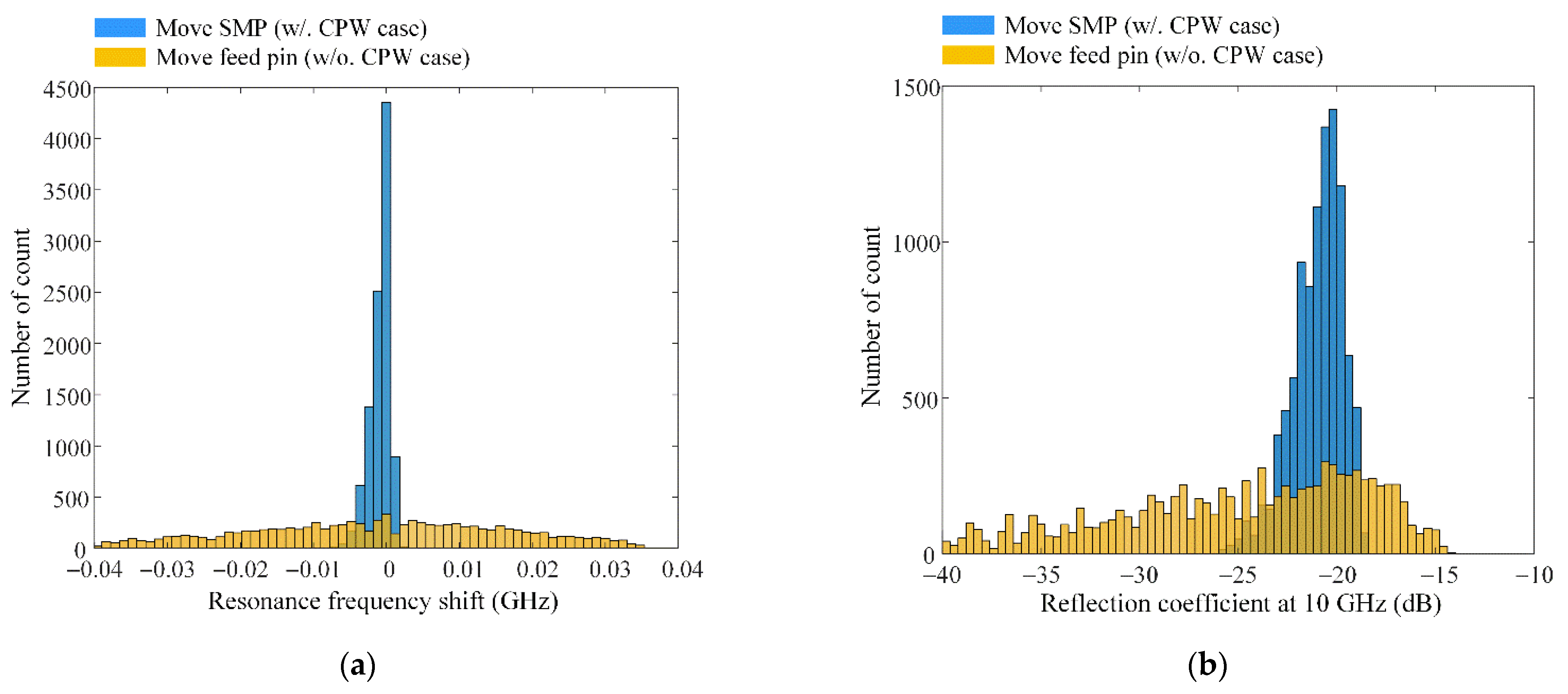
3. Durability Evaluation Using Monte Carlo Simulations

To more accurately evaluate the durability of the proposed design, we examine the antenna performance changes (i.e., resonant frequency shifts) according to the existence of the CPW layer. Figure 6 shows the resonance frequency shift according to the unwanted movement of the SMP connector due to external shocks. To clearly examine the influence of the external shocks, we assume that the SMP connector is moved only along x- and y-axes by the external shocks, as shown in Figure 6a. Then, we simulate the proposed antenna with and without the CPW layer in the observation frequency from 9.5 GHz to 10.5 GHz. The SMP connector is gradually moved with an interval of 0.01 mm (−0.3 mm ≤ xn ≤ 0.3 mm and −0.3 mm ≤ yn ≤ 0.3 mm, n = 1, 2) to observe all movement for the external shock assumption. In the proposed case, the shift in resonance frequency is observed to be very small, which is less than 4 MHz, as shown in Figure 6b. Without the CPW layer, the resonance frequency shift varies up to 35 MHz according to the unwanted movement of the SMP connector, as shown in Figure 6c.
Figure 7 illustrates statistical histograms for the durability evaluation of the antenna design with and without the CPW layer. To obtain the histogram results, a Monte Carlo simulation is performed according to random movements of the SMP connector with 10,000 iterations. The movement distribution of the SMP connector is assumed to be a discrete Gaussian distribution [28], which has a zero mean and a one standard deviation distribution. At each iteration, we observe the antenna performance change such as the resonance frequency shift and the reflection coefficient level, which is summarized in Table 2. Figure 7a presents the histograms for the resonance frequency shift. The mean and standard deviation of the proposed antenna are 0 and 0.0014, and those of the X-band patch without the CPW layer are 0 and 0.0177, respectively. Figure 7b represents the histograms for the reflection coefficient at 10 GHz. The mean and standard deviation of the proposed antenna are −21 dB and 1.28; on the other hand, those of the X-band patch without the CPW layer are −26.9 dB and 8.82. From Table 2, the proposed antenna has a smaller standard deviation for the resonance frequency shift and reflection coefficient than without CPW case. The smaller standard deviation means that antenna performance can be maintained even if the connector is shaken from the external shocks. On the other hand, higher standard deviation means that the antenna without CPW may have the vulnerable performance from the external shocks. Thus, the results demonstrate that the proposed antenna has a high durability, as confirmed by the small standard deviation values in the resonant frequency shift and reflection coefficient change.

4. Conclusions

We investigated the high-durable X-band patch antenna with a CPW feeding network that can directly connect the upper antenna and the lower TRM without additional cabling. To improve the durability of the antenna, both the SMP connector and the feed-pin were separated through the CPW layer, so that when unwanted feed-pin movement occurred due to external shocks, the deterioration of the antenna performance could be minimized. In order to verify the antenna feasibility, reflection coefficient and radiation pattern were measured in full EM anechoic chamber. The reflection coefficient was measured to be −27 dB, and the boresight gain and HPBW were observed to be 5.8 dBi and 99°, respectively. To more accurately evaluate the high-durability design, the Monte Carlo simulation was performed according to the unwanted movement of the SMP connector with the 10,000 iterations. For the resonance frequency shift, the mean and standard deviation of the proposed antenna were 0 and 0.0014, respectively. On the other hand, the mean and standard deviation of the X-band patch without the CPW layer were 0 and 0.0177, respectively. The results demonstrated that the proposed antenna with high-durability design was suitable for military ship applications exposed to various external shocks.

Author Contributions

Conceptualization, D.J., T.H.L., D.K., H.C. and S.W.; formal analysis, D.J., D.K. and S.W.; funding acquisition, H.C.; investigation, D.J. and S.W.; methodology, D.J. and T.H.L.; project administration, H.C.; software, D.J. and T.H.L.; supervision, H.C.; validation, D.J., T.H.L., D.K., H.C. and S.W.; visualization, D.J. and T.H.L.; writing—original draft, D.J. and S.W.; writing—review and editing, D.J., H.C. and S.W. All authors have read and agreed to the published version of the manuscript.

Funding

This research received no external funding.

Acknowledgments

This research has been supported by the Defense Challengeable Future Technology Program of Agency for Defense Development, Republic of Korea.

Conflicts of Interest

The authors declare no conflict of interest.

References

  1. Locker, C.; Vaupel, T.; Eibert, T.F. Radiation efficient unidirectional low-profile slot antenna elements for X-band application. IEEE Trans. Antennas Propag. 2005, 53, 2765–2768. [Google Scholar] [CrossRef]
  2. Dastkhosh, A.R.; Oskouei, H.D.; Khademevatan, G. Compact low weight high gain broadband antenna by polarization-rotation technique for X-band radar. Int. J. Antennas Propag. 2014, 2014, 1–10. [Google Scholar] [CrossRef]
  3. Zhou, Y.; Wang, T.; Hu, R.; Su, H.; Liu, Y.; Liu, X.; Suo, J.; Snoussi, H. Multiple kernelized correlation filters (MKCF) for extended object tracking using X-band marine radar data. IEEE Trans. Signal Process. 2019, 67, 3676–3688. [Google Scholar] [CrossRef]
  4. Wang, A.; Krishnamurthy, V. Signal interpretation of multifunction radars: Modeling and statistical signal processing with Stochastic Context Free Grammar. IEEE Trans. Signal Process. 2008, 56, 1106–1119. [Google Scholar] [CrossRef]
  5. Kwon, G.; Park, J.; Kim, D.; Hwang, K.C. Optimization of a shared-aperture dual-band transmitting/receiving array antenna for radar applications. IEEE Trans. Antennas Propag. 2017, 65, 7038–7051. [Google Scholar] [CrossRef]
  6. Li, H.-P.; Wang, G.-M.; Gao, X.-J.; Liang, J.-G.; Hou, H.-S. A novel metasurface for dual-mode and dual-band flat high-gain antenna application. IEEE Trans. Antennas Propag. 2018, 66, 3706–3711. [Google Scholar] [CrossRef]
  7. Eldek, A.A.; Elsherbeni, A.Z.; Smith, C.E. Wide-band modified printed bow-tie antenna with single and dual polarization for C- and X-band applications. IEEE Trans. Antennas Propag. 2005, 53, 3067–3072. [Google Scholar] [CrossRef]
  8. Alhalabi, R.A.; Rebeiz, G.M. High-efficiency angled-dipole antennas for millimeter-wave phased array applications. IEEE Trans. Antennas Propag. 2008, 56, 3136–3142. [Google Scholar] [CrossRef]
  9. Eldek, A.A. Ultrawideband double rhombus antenna with stable radiation patterns for phased array applications. IEEE Trans. Antennas Propag. 2007, 55, 84–91. [Google Scholar] [CrossRef]
  10. Khamsalee, P.; Mesawad, P.; Wongsan, R. Hybrid metamaterial for the secondary radar antenna system. J. Electromagn. Eng. Sci. 2020, 20, 221–233. [Google Scholar] [CrossRef]
  11. Luo, G.Q.; Hong, W.; Tang, H.J.; Chen, J.X.; Yin, X.X.; Kuai, Z.Q.; Wu, K. Filtenna consisting of horn antenna and substrate integrated waveguide cavity FSS. IEEE Trans. Antennas Propag. 2007, 55, 92–98. [Google Scholar] [CrossRef]
  12. Bilgic, M.M.; Yegin, K. Wideband offset slot-coupled patch antenna array for X/Ku-band multimode radars. IEEE Antennas Wirel. Propag. Lett. 2014, 13, 157–160. [Google Scholar] [CrossRef]
  13. Kong, D.K.; Kim, J.; Woo, D.; Yoon, Y.J. Broadband modified proximity coupled patch antenna with cavity-backed configuration. J. Electromagn. Eng. Sci. 2021, 21, 8–14. [Google Scholar] [CrossRef]
  14. Rana, B.; Lee, I.-G.; Hong, I.-P. Experimental characterization of 2 × 2 electronically reconfigurable 1 bit unit cells for a beamforming transmitarray at X Band. J. Electromagn. Eng. Sci. 2021, 21, 153–160. [Google Scholar] [CrossRef]
  15. Zahra, H.; Hussain, M.; Naqvi, S.I.; Abbas, S.M.; Mukhopadhyay, S. A simple monopole antenna with a switchable beam for 5G millimeter-wave communication systems. Electronics 2021, 10, 2870. [Google Scholar] [CrossRef]
  16. Wang, M.; Zhu, Q.; Chan, C.H. Wideband, low-profile slot-fed dipole-patch antenna and array. IEEE Antennas Wirel. Propag. Lett. 2020, 19, 2250–2254. [Google Scholar] [CrossRef]
  17. Ketavath, K.N.; Gopi, D.; Rani, S.S. In-vitro test of miniaturized CPW-fed implantable conformal patch antenna at ISM band for biomedical applications. IEEE Access 2019, 7, 43547–43554. [Google Scholar] [CrossRef]
  18. Li, X.-P.; Xu, G.; Ma, M.-R.; Duan, C.-J. UWB dual-band-notched lanky-leaf-shaped antenna with loaded half-square-like slots for communication system. Electronics 2021, 10, 1991. [Google Scholar] [CrossRef]
  19. Al-Gburi, A.J.A.; Ibrahim, I.B.M.; Zakaria, Z.; Ahmad, B.H.; Shairi, N.A.B.; Zeain, M.Y. High gain of UWB planar antenna utilising FSS reflector for UWB applications. CMC-Comput. Mater. Contin. 2021, 70, 1419–1436. [Google Scholar] [CrossRef]
  20. Jang, D.; Yoo, S.; Choo, H. Design of patch antenna with polarization control module to achieve broad 3-dB gain bandwidth over entire AR range. Microw. Opt. Technol. Lett. 2020, 62, 2606–2610. [Google Scholar] [CrossRef]
  21. Aboserwal, N.; Salazar-Cerreno, J.L.; Qamar, Z. An ultra-compact X-band dual-polarized slotted waveguide array unit cell for large E-scanning radar systems. IEEE Access 2020, 8, 210651–210662. [Google Scholar] [CrossRef]
  22. Haraz, O.M.; Elboushi, A.; Alshebeili, S.A.; Sebak, A.-R. Dense dielectric patch array antenna with improved radiation characteristics using EBG ground structure and dielectric superstrate for future 5G cellular networks. IEEE Access 2014, 2, 909–913. [Google Scholar] [CrossRef]
  23. George, E.; Das, D.; Osterman, M.; Pecht, M. Thermal cycling reliability of lead-free solders (SAC305 and Sn3.5Ag) for high-temperature applications. IEEE Trans. Device Mater. Reliab. 2011, 11, 328–338. [Google Scholar] [CrossRef] [Green Version]
  24. Zhang, L.-K.; Wang, Y.-X.; Li, J.-Y.; Feng, Y.; Zhang, W. Cavity-backed circularly polarized cross-dipole phased arrays. IEEE Antennas Wirel. Propag. Lett. 2021, 20, 1656–1660. [Google Scholar] [CrossRef]
  25. SMP-MSSB-PCS15T, Amphenol RF. Available online: https://kr.mouser.com/manufacturer/amphenolrf/ (accessed on 1 November 2021).
  26. FEKO EM Software, Altair. Available online: https://www.altair.co.kr/feko/ (accessed on 1 November 2021).
  27. Balanis, C.A. Antenna Theory Analysis and Design, 3rd ed.; John Wiley & Sons, Inc.: Hoboken, NJ, USA, 2005; pp. 811–883. [Google Scholar]
  28. Wang, Z.; Ling, C. Lattice gaussian sampling by Markov Chain Monte Carlo: Bounded distance decoding and trapdoor sampling. IEEE Trans. Inf. Theory 2019, 65, 3630–3645. [Google Scholar] [CrossRef] [Green Version]
Figure 1. Geometry of the X-band patch antenna with the CPW layer: (a) top view; (b) bottom view; (c) side view.
Electronics 11 00553 g001
Figure 2. Photograph of the proposed antenna: (a) top view; (b) bottom view, (c) zoomed CPW.
Electronics 11 00553 g002
Figure 3. Reflection coefficients of the proposed antenna.
Electronics 11 00553 g003
Figure 4. Radiation patterns of the proposed antenna.
Electronics 11 00553 g004
Figure 5. Current distribution on the patch surface.
Electronics 11 00553 g005
Figure 6. Resonance frequency shift according to the SMP connector movement: (a) geometry of the SMP connector movement with and without the CPW layer; (b) with CPW case; (c) w/o CPW case.
Electronics 11 00553 g006aElectronics 11 00553 g006b
Figure 7. Histograms for durability evaluation: (a) resonance frequency shift; (b) reflection coefficient at 10 GHz.
Electronics 11 00553 g007
Table 1. Geometrical parameters of the proposed antenna.
ParameterValue (mm)
l9
fp2.3
h10.8
h20.8
g10.6
g20.1
wt11
wt20.75
lt0.85
Sx5
Sy5
Table 2. Summarization of the durability evaluation.
CharacteristicCaseMeanStandard Deviation
Resonance
Frequency
With CPW00.0014
Without CPW00.0177
Reflection coefficientat 10 GHzWith CPW−21 dB1.28
Without CPW−26.9 dB8.82
Publisher’s Note: MDPI stays neutral with regard to jurisdictional claims in published maps and institutional affiliations.

