Article

Rate Maximization in a UAV Based Full-Duplex Multi-User Communication Network Using Multi-Objective Optimization

1
Lyle School of Engineering, Southern Methodist University, Dallas, TX 75275, USA
2
Department of Computer Science, Portland State University, Portland, OR 97201, USA
*
Author to whom correspondence should be addressed.
Electronics 2022, 11(3), 401; https://doi.org/10.3390/electronics11030401
Submission received: 5 December 2021 / Revised: 24 January 2022 / Accepted: 25 January 2022 / Published: 28 January 2022
(This article belongs to the Special Issue Wireless Networking: Theory, Practice, and Applications)

Abstract

:
In this paper, we study an unmanned-aerial-vehicle (UAV) based full-duplex (FD) multi-user communication network, where a UAV is deployed as a multiple-input–multiple-output (MIMO) FD base station (BS) to serve multiple FD users on the ground. We propose a multi-objective optimization framework which considers two desirable objective functions, namely sum uplink (UL) rate maximization and sum downlink (DL) rate maximization while providing quality-of-service to all the users in the communication network. A novel resource allocation multi-objective-optimization-problem (MOOP) is designed which optimizes the downlink beamformer, the beamwidth angle, and the 3D position of the UAV, and also the UL power of the FD users. The formulated MOOP is a non-convex problem which is generally intractable. To handle the MOOP, a weighted Tchebycheff method is proposed, which converts the problem to the single-objective-optimization-problem (SOOP). Further, an alternative optimization approach is used, where SOOP is converted in to multiple sub-problems and optimization variables are operated alternatively. The numerical results show a trade-off region between sum UL and sum DL rate, and also validate that the considered FD system provides substantial improvement over traditional HD systems.

1. Introduction

In the past few years, Unmanned Aerial Vehicle (UAV) communication systems have become a focus of researchers for their unique characteristics that produce interesting communications problems. In particular, UAVs are expected to be integral in various applications in 5G wireless systems. Due to the fact that UAVs are easily operable, highly maneuverable, and have increasing payload capability, it is expected that the use of UAVs will increase in the coming years. There are numerous applications of UAVs including emergency search and rescue, communication relaying, package delivery, emergency broadband service, and infrastructure inspection [1].
In the telecommunication domain, a common use of the UAV is a mobile base station (BS) to form a wireless network [2]. In [3], the authors worked on multi-UAV communication systems to serve ground users and primarily focused on designing the UAV trajectories and transmit power to improve throughput. UAVs can also be utilized to work as a relay. The authors in [4] worked on UAV-aided relay systems to minimize outage of the system by optimizing trajectory and transmit power of the UAV. In [5], authors studied joint optimization of altitude and beamwidth of UAV to improve throughput in three different UAV enabled multi-user communication models, where the UAV was assumed to have directional antennas with adjustable beamwidth angles. The results show that the optimal altitude and beamwidth angle critically depend on the communication model. Furthermore, the antenna beamwidth optimization was also considered in [6].
Concurrently, the increase in wireless data traffic forced the limits of communication systems in terms of reliability and throughput [7]. In band full duplex (IBFD) communication allows bi-directional communication at the same frequency and time, which doubles the system capacity and improve spectrum efficiency compared to the traditional half duplex (HD) systems [8,9,10]. The IBFD systems are of great interest among researchers, and there has been some work in the literature where IBFD systems are utilized with UAVs to propose and solve new problems. For example, in [11], the UAV was deployed as a full duplex (FD) relay to minimize the outage probability of the relaying system. In [12], spectrum sharing planning was studied in a scenario where FD UAV was considered as a relay in device-to-device cellular systems. In [13], FD UAV-based small cell wireless system was considered, where the UAV was deployed as a base station to serve downlink (DL) and uplink (UL) users in a FD manner. The UAV trajectory, user scheduling, and UL user transmit power are alternately optimized to maximize the total capacity of the system.
In addition to the spectral efficiency, beamforming with MIMO system has gained wide research attention for the design of a next generation wireless network. Beamforming is a technique used for directional transmission and reception at a particular device/user, rather than spreading the wireless signal in all directions, thereby reducing interference and increasing the wireless link gain. In [14], transmit and receive beamforming optimization for a IBFD cloud radio access network (CRAN) was considered. Similarly, beamforming optimization for power over wireless FD MIMO systems was discussed in [15], where considerable performance gains were achieved over the HD scheme when the time splitting parameter and beamformer are jointly optimized. The UAV enabled FD relay was considered in [16], where beamforming and power allocation were jointly optimized to maximize the instantaneous data rate of the system. In [17], a sum-rate maximization problem for FD multi-user MIMO system was considered, where the authors proposed a beamformer design for the UL and DL FD link. Similarly, in [18], a power efficient resource allocation algorithm was considered in a multi-user FD network. The authors proposed a multi-objective optimization framework to jointly optimize the beamformer at the MIMO FD base station, and the UL transmit power from the HD users.
In recent works, effectiveness of FD in a UAV network was shown in [19], where the authors considered maximizing the DL sum rate while maintaining the minimum quality-of-service (QoS) for the UL users, by optimizing the resources and location of the UAV. In [20], FD was considered in a UAV-assisted wireless powered Internet-of-Things (IoT) network, where the FD UAV collects data from the target IoT device and simultaneously charges remaining devices utilizing fly–hover–communicate protocol. Moreover, a FD UAV relay network was considered in [21], to jointly optimize the HD UL and DL users scheduling, and the UAV trajectory. Finally, in [22], a UAV was considered to charge nodes using Wireless powered communication via backscatter and/or harvest-then-transmit in the IoT network. The UAV trajectory with other resource allocations were optimized to maximize the energy efficiency of the network. The UAV serves all the nodes by sequentially visiting each node in respective time slot which leads to increase in energy consumption due to propulsion. Noting that the propulsion energy consumption during hover is usually less than the frequent maneuverings [23]. In this work, we consider optimal UAV deployment with resource allocation to serve multiple users on the ground.
To the best of our knowledge, UAV coverage area optimization with resource allocation was never considered in an MIMO UAV FD network. Coverage area optimization has been considered for traditional HD single antenna system in the literature [5,24], where antenna beamwidth and altitude of the UAV were optimized to maximize the system performance. For FD system, adjustable beamwidth antenna was also considered in [19] for directional communication from UAV. Here, we consider coverage optimization by including adjustable beamwidth antennas in an MIMO FD UAV BS and formulate bi-direction FD rates where interference terms are shown to be a function of antenna beamwidth. In the following, we propose a novel multi-objective-optimization-problem (MOOP) to maximize the sum UL-DL rate while providing QoS for a multi-user MIMO FD UAV network. The proposed formulation takes into account the coverage area (beamwidth and altitude), beamformer, horizontal location of the UAV, and UL transmit power of the FD users. The optimization problem is non-convex and non-tractable. MOOP was also considered in [20], where a deep learning approach is used to solve the conflicting system objectives. Contrary, we first adopt weighted Tchebycheff method to convert MOOP to a single-objective-optimization-problem (SOOP). SOOP are singular weighted/fractional order objective systems which are discussed in [25,26]. Second, we divide SOOP into multiple sub-problems and provide an independent solution for each sub-problem. Lastly, we propose a joint optimization algorithm to solve the proposed problem.
The main contribution of the paper are summarized as follows:
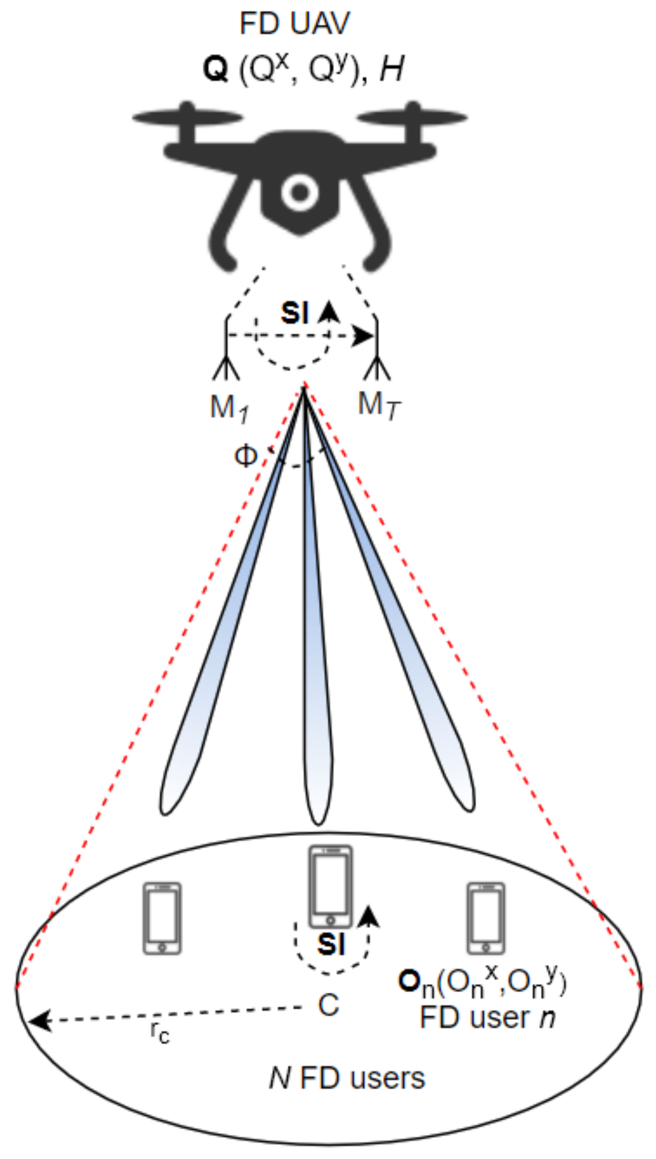
  • We consider adjustable beamwidth antennas on the FD MIMO UAV in a multi-user aerial network where the users have FD capability and propose a novel optimization problem to optimize the UAV’s coverage area with resource allocation;
  • We propose a computationally-efficient solution for transmit beamforming from FD MIMO UAV towards the single antenna FD users by utilizing a zero-forcing (ZF) approach;
  • We found that the UL power optimization in a multi-user FD aerial network leads to a non-convexity in the optimization problem due to co-channel interference;
  • We proposed a joint optimization solution for the optimization of DL beamformer, coverage area and location of the UAV, and UL power of the users in a multi-user FD aerial network when the objective is to maximize the sum bi-directional FD rate;
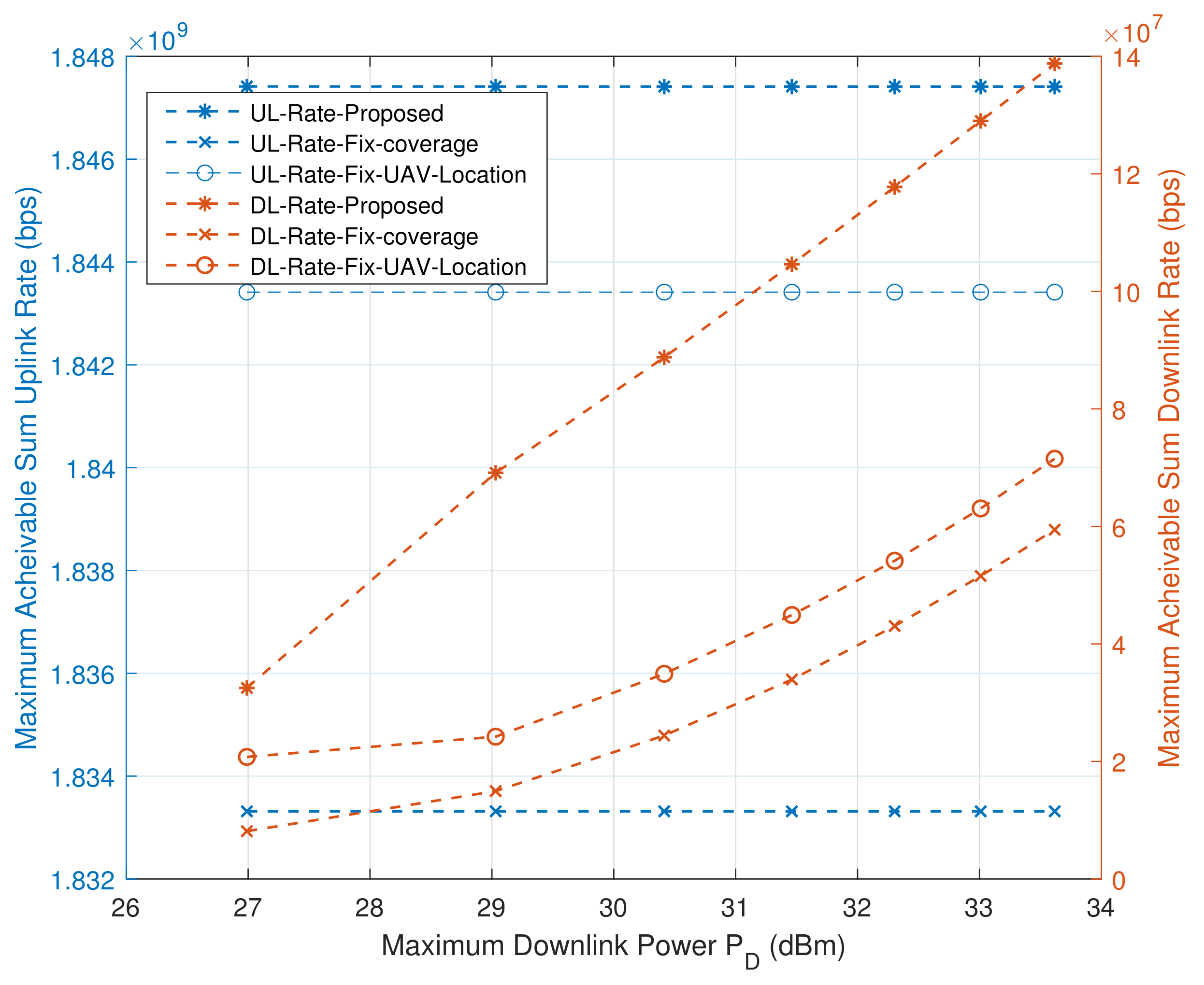
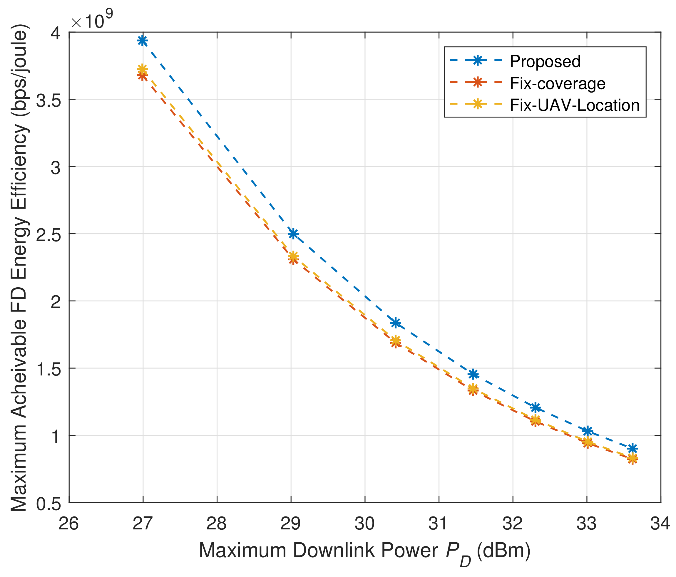
  • Numerical results show that the proposed solution to the MOOP achieves better performance compared to the baseline FD algorithms. Similarly, FD functionality in the proposed system model provides notable performance improvement over a HD system.
The rest of the paper is organized as follows. In Section 2, the system model of a UAV-based FD multi-user communication network is presented, including the channel model and the relevant performance metrics. The proposed MOOP formulation is described in Section 3, where the sum UL and DL rates are maximized. The optimization solution, proposed joint resource allocation algorithm, and complexity and convergence analysis of the algorithm are investigated in Section 4. The numerical results based performance analysis of the proposed algorithm is presented in Section 5. Finally, the paper is concluded in Section 6.
N o t a t i o n : The bold face lower case and capital case letters are used to denote vectors and matrices, respectively. X H , Trace ( X ) , Rank ( X ) , and X 1 indicate the Hermitian transpose, trace, rank, and inverse of the matrix X , respectively. X 0 shows that X is a positive definite matrix. | | . | | denotes the Euclidean vector norm. C M × M and I M denotes the space of M × M matrices with complex entries and M × M identity matrix, respectively. E ( . ) denotes the expectation with respect to random variable x, and CN ( μ , σ 2 ) denotes the circularly-symmetric complex Gaussian distribution with mean μ and variance σ 2 .

2. System Model

In this section, we present the UAV based multi-user FD communication network. We then introduce a multi-user MIMO FD communication model and performance metrics for evaluating our algorithms.

2.1. System Model

Consider a UAV-based FD communication network as depicted in Figure 1. The system consists of a UAV-based FD radio BS and N FD users. The UAV BS is equipped with M T antennas, while each user n { 1 , 2 , , N } is equipped with a single antenna for simultaneous UL and DL transmission in the same frequency band. An example of such a feasible solution is a circulator-based FD radio prototype at both BS and users which can achieve bi-directional transmission on the same antenna while providing low hardware complexity [27]. A UAV is deployed with the altitude H and the horizontal location Q = ( Q x , Q y ) and the location of users are denoted by O n = ( O n x , O n y ) .
The UAV is equipped with adjustable beamwidth antennas to modify the coverage area for the users. Since the MIMO antennas on the commercial UAVs are usually close to each other, we assume that the azimuth and the elevation half-power beamwidth of all the M T antennas are equal and defined by 2 Φ ( 0 , π ) radians. The antenna gain in the direction ( θ , Ψ ) can be determined by:
G = G o Φ 2 Φ θ Φ , Φ Ψ Φ , g 0 otherwise .
Here, θ and Ψ are the azimuth angle and the elevation angle, respectively. In (1), the former interval corresponds to the actual beamwidth of the antenna, and latter is the range of θ and Ψ values outside the beamwidth. Additionally, G o = 30 , 000 2 2 × ( π 180 ) 2 2.2846 , and g is the channel gain outside the beamwidth of the antenna [5]. To simplify, we set g = 0 . In contrast, each user n is equipped with an omni-directional antenna. Therefore, radius of the ground coverage area of the UAV is defined by r c = H tan ( Φ ) .

2.2. Channel Model and Performance Metrics

In this work, we assume that the UL and DL channels between the UAV and user n have similar channel characteristics. Since a UAV to user channel is mostly dominated by the line-of-sight path, the UL and DL channels can be written as
h n = h ¯ n ( H 2 + Q O n 2 ) ϵ 2 , n = 1 , 2 , , N .
Here, h n and h ¯ n C ( M T × 1 ) . Each element of h ¯ n is a random variable with zero mean and unit variance, and ϵ is the path loss exponent which is taken as ϵ = 2 . The received signal at the FD BS and FD user n can be written as (3) and (4), respectively.
y UL = G o Φ 2 n = 1 N p n h n S n b + G o Φ 2 n = 1 N h D κ n S n a self - interference + π D
y n D L = G o Φ 2 h n H κ n S n a + m n N p m g { m , n } S m b co - channel interference + p n g { n , n } S n b self - interference + G o Φ 2 m n N h n H κ m S m a multi - user interference + π n
Here, S n a C and κ n C M T × 1 are the information bearing signal and transmit beamforming vector from the FD BS to user n, respectively. S n b C and p n are the UL transmit data and power sent from user n to the FD BS, respectively. g { m , n } = g o d { m , n } ϵ / 2 C denotes the channel between user m { 1 , 2 , , N } and user n, where g o is the channel gain at reference distance of 1 meter, d { m , n } is the distance between user m and n, and m n . g { n , n } C and h D C M T × M T are the self-interference (SI) channels at user n and the FD BS, respectively. π D CN ( 0 , σ D 2 I M T ) and π n CN ( 0 , σ n 2 ) denote the additive white Gaussian noise at the FD BS and user n, respectively. In (3), the term G o Φ 2 n = 1 N h D κ n S n a represents the SI at the FD BS. Without loss of generality, it is assumed that E ( | S n a | 2 ) = E ( | S n b | 2 ) = 1 , n { 1 , 2 , , N } . In (4), the term m n N g { m , n } S m b p m denotes the co-channel interference formed by UL transmissions from the users, the term g { n , n } S n b p n represents the SI at the user n, and the term G o Φ 2 m n N h n H κ m S m a shows the multi-user interference in the downlink channel. Additionally, we assume that the perfect channel state information for all users is known at the FD BS.
The FD BS applies a beamformer to the received signal y UL . The received signal after beamforming for the information transmitted from user n can be written as
y n UL = G o Φ 2 p n h n H ω n S n b + m n N p m h m H ω n S m b + G o Φ 2 m = 1 N ω n H h D κ m S n a + ω n H π D .
Here, ω n C M T × 1 is the receive beamforming vector at the FD BS to decode information transmitted from the user n. We adopt ZF beamforming for ω n for two main reasons: firstly, it requires low computation resources compared to the MMSE beamforming (Basic analysis and performance comparison of ZF and MMSE beamforming are given in [28]) and, therefore, it can be implemented more efficiently for UAV network that has limited computational resources, and secondly, the optimization problem is mathematically tractable due to the cancellation of interference terms in uplink rate expression as shown below. It is also reported that ZF beamforming approaches the performance of optimum MMSE beamforming when the noise is not a dominating factor or the number of antennas is sufficiently large in the system [29,30]. Additionally, the BS is usually equipped with a low noise amplifier, which facilitates in reduction in the noise at the BS. The receive beamforming vector for user n is calculated at the FD BS according to:
ω n = ( v n ( Z H Z ) 1 Z H ) H | | ( v n ( Z H Z ) 1 Z H ) H | | .
Here, v n = [ 0 , , 0 ( N n ) , 1 , 0 , , 0 ( N n ) ] , and Z = [ h 1 , . , h N ] . Additionally, to facilitate uplink signal detection, the number of antennas on the FD BS is assumed to be higher than the number of users.
The DL rate at user n for the information transmitted from FD BS can be written as
R n D L = W log 2 1 + G o Φ 2 | h n H κ n | 2 m n N | p m g { m , n } | 2 + | p n g { n , n } | 2 + G o Φ 2 m n N | h n H κ m | 2 + W σ n 2 ,
where W is the system bandwidth. The UL rate at FD BS for the information transmitted from user n can be written as
R n U L = W log 2 1 + | p n h n H ω n | 2 m n N | p m h m H ω n | 2 + G o Φ 2 m = 1 N | ω n H h D κ m | 2 + W | | ω n | | 2 σ D 2 .

3. Proposed MOOP Formulation

In this work, we study the maximization of two objective functions and formulate a MOOP. We aim to maximize the sum UL and DL rates while maintaining minimum QoS to the ground users by jointly optimizing beamwidth Φ , horizontal location Q and altitude H of the UAV, and UL power of the users. The proposed MOOP is formulated as follows:
max κ n , H , Φ , Q , p n n = 1 N R n D L
max κ n , H , Φ , Q , p n n = 1 N R n U L
s . t . R n U L R n U L min , n = 1 , 2 , , N ,
R n D L R n D L min , n = 1 , 2 , , N ,
| | κ n | | 2 P D / N , n = 1 , 2 , , N ,
| | Q O n | | 2 H 2 tan 2 ( Φ ) , n = 1 , 2 , , N ,
0 p n P B , n = 1 , 2 , , N ,
H min H H max ,
Φ min Φ Φ max .
Here, P D and P B are the maximum DL power for the FD BS and the maximum UL power for the users, respectively. [ H min , H max ] is the range of the UAV altitude H, which is determined by local authority regulations. R n U L min and R n D L min are the minimum required data rate for QoS in the UL and DL, respectively. [ Φ min , Φ max ] is the half-beamwidth range, which is determined by an antenna beamwidth tuning technique. Constraint (9f) guarantees the placement of users in the coverage area of a UAV. Note that the MOOP helps to learn the trade-off between conflicting system objective functions using the concept of Pareto optimality. In the Pareto optimality or efficiency, a point is only Pareto optimal if there is no other point which improves at least one of the objective functions while keeping the same performance of the other objective functions.

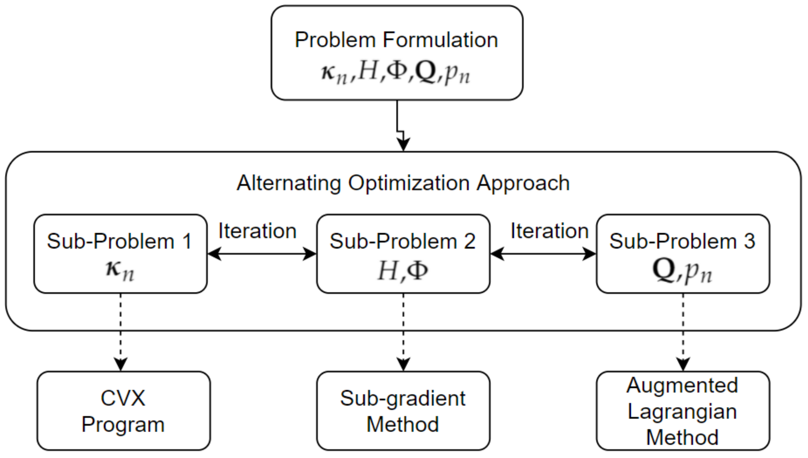
4. Solution of the MOOP

The optimization problem (9) is non-convex due to non-convex objective functions and constraints. It is hard to find the optimal solution. We approach the proposed problem by first converting the MOOP to SOOP using the weighted Tchebycheff method. Then, we divide the SOOP in to three sub-problems and utilize alternating optimization algorithm to handle them iteratively. In the weighted Tchebycheff method, multiple objective functions are converted to a single objective by applying weights to each objective functions. The problem (9) can be reformulated as the following SOOP.
max κ n , H , Φ , Q , p n n = 1 N α R n U L + ( 1 α ) R n D L
s . t . R n U L R n U L min , n = 1 , 2 , , N ,
R n D L R n D L min , n = 1 , 2 , , N ,
| | κ n | | 2 P D / N , n = 1 , 2 , , N ,
| | Q O n | | 2 H 2 tan 2 ( Φ ) , n = 1 , 2 , , N ,
0 p n P B , n = 1 , 2 , , N ,
H min H H max ,
Φ min Φ Φ max ,
where α is weighting coefficient. The weighted Tchebycheff method guarantees to generate a set of Pareto optimal points, even for a non-convex MOOP. The problem (10) is still non-convex due to non-convex objective function (10a) and constraints (10b) and (10c). We divide the SOOP into three sub-problems that are described in the three subsequent subsections.

4.1. Optimal Downlink Beamformer

With fixed values for H, Φ , Q , and p n , problem (10) can be reformulated as the following sub-problem 1:
S u b p r o b l e m 1 : max κ n n = 1 N α R n U L + ( 1 α ) R n D L
s . t . R n U L R n U L min , n = 1 , 2 , , N ,
R n D L R n D L min , n = 1 , 2 , , N ,
| | κ n | | 2 P D / N , n = 1 , 2 , , N .
Since, κ n is the only optimization variable in problem (11), the constraints that are not associated with κ n are not required. The problem (11) is still non-convex for the following two main reasons: (i) a multi-user interference term in the DL rate and ( i i ) an increasing function κ n of DL rate exists, while there is a decreasing function for the UL rate, which makes objective (11a) a difference of two concave functions. Therefore, we proceed with the ZF approach to simplify problem (11). We assume that for user n, DL beamformer vector κ n creates a null in the direction of the SI channel h D at the FD BS. Additionally, for user n, the projections of the channel vector h n on the DL beamformer vectors of remaining N 1 users are 0. In other words, the following holds: h D κ n = 0 , n = 1 , 2 , , N , and h n κ m = 0 , [ m , n ] = 1 , 2 , , N , m n .
In order to solve problem (11) efficiently, we reformulate the problem by adopting a semi-definite programming (SDP) method. To assist the SDP, we define K n = κ n κ n H , H D = h D h D H , and H n = h n h n H . The simplified SDP problem is given by:
max K n n = 1 N ( 1 α ) W log 2 1 + G o Φ 2 Trace ( H n K n ) m n N | g { m , n } | 2 p m + | g { n , n } | 2 p n + W σ n 2
s . t . W log 2 1 + G o Φ 2 Trace ( H n K n ) m n N | g { m , n } | 2 p m + | g { n , n } | 2 p n + W σ n 2 R n D L min , n = 1 , 2 , , N ,
T r a c e ( K n ) = P D / N , n = 1 , 2 , , N ,
K n 0 , n = 1 , 2 , , N ,
Trace ( H D K n ) = 0 , n = 1 , 2 , , N ,
Trace ( H m K n ) = 0 , ( n , m ) = 1 , 2 , , N , m n ,
Rank ( K n ) 1 , n = 1 , 2 , , N .
The problem (12) is still non-convex because of the rank constraint (12g). Rank constrained problems are usually non-polynomial hard problems. Therefore, we relaxed the constraint (12g) by removing it from the SDP problem (12). The relaxed problem is given by:
max K n n = 1 N ( 1 α ) W log 2 1 + G o Φ 2 Trace ( H n K n ) m n N | g { m , n } | 2 p m + | g { n , n } | 2 p n + W σ n 2
s . t . W log 2 1 + G o Φ 2 Trace ( H n K n ) m n N | g { m , n } | 2 p m + | g { n , n } | 2 p n + W σ n 2 R n D L min , n = 1 , 2 , , N ,
T r a c e ( K n ) = P D / N , n = 1 , 2 , , N ,
K n 0 , n = 1 , 2 , , N ,
Trace ( H D K n ) = 0 , n = 1 , 2 , , N ,
Trace ( H m K n ) = 0 , ( n , m ) = 1 , 2 , , N , m n .
The problem (13) is known as a semi-definite relaxed (SDR) problem. Additionally, it is a convex problem and can be efficiently solved using convex problem solvers such as CVX [31]. Once solved, κ n can be found using the eigenvalue decomposition of K n . The solution of problem (13) is optimal if the obtained matrix K n is Rank 1. Otherwise, it provides a lower bound for the problem (12). For the case when Rank ( K n ) 1 , n = 1 , 2 , , N , there are multiple methods in literature to improve the solution [32,33]. We follow the heuristic solution provided in [33], which implies that for user n, choose κ n as the principle eigenvector of K n , which corresponds to the largest eigenvalue of K n .

4.2. Optimal Coverage (Altitude and Beamwidth)

With fixed κ n , Q , Φ and p n , problem (10) can be reformulated as the following sub-problem 2a:
S u b p r o b l e m 2 a : max H n = 1 N ( α A n + ( 1 α ) B n )
s . t . A n R n U L min , n = 1 , 2 , , N ,
B n R n D L min , n = 1 , 2 , , N ,
| | Q O n | | 2 H 2 tan 2 ( Φ ) , n = 1 , 2 , , N ,
H min H H max ,
where
A n = W log 2 1 + | h n H ω n p n | 2 W | | ω n | | 2 σ D 2 ,
and
B n = W log 2 1 + G o Φ 2 | h n H κ n | 2 m n N | p m g { m , n } | 2 + | p n g { n , n } | 2 + W σ n 2
are the updated UL and DL rates after applying the ZF constraints of the DL beamformer, respectively. Similarly, with fixed κ n , Q , H and p n , problem (10) can be reformulated as the following sub-problem 2b.
S u b p r o b l e m 2 b : max Φ n = 1 N ( 1 α ) B n
s . t . B n R n D L min , n = 1 , 2 , , N ,
| | Q O n | | 2 H 2 tan 2 ( Φ ) , n = 1 , 2 , , N ,
Φ min Φ Φ max .
The problem (14) and (17) are convex optimization problems and can be solved using standard Lagrangian methods [34]. The Lagrangian functions of the convex problems are given by:
L ( H , λ , Ω , δ ) = n = 1 N ( α A n + ( 1 α ) B n ) + n = 1 N Ω n ( B n R n D L min ) + n = 1 N λ n ( A n R n U L min ) + n = 1 N δ n ( H 2 tan 2 ( Φ ) | | Q O n | | 2 ) .
L ( Φ , U , J ) = n = 1 N ( 1 α ) B n + n = 1 N U n ( B n R n D L min ) + n = 1 N J n ( H 2 tan 2 ( Φ ) | | Q O n | | 2 ) .
Here, λ = [ λ 1 , , λ N ] 0 , Ω = [ Ω 1 , , Ω N ] 0 and δ = [ δ 1 , , δ N ] 0 are the Lagrange multipliers associated with constraints (14b), (14c) and (14d) in problem (14); and U = [ U 1 , , U N ] 0 and J = [ J 1 , , J N ] 0 are the Lagrange multipliers associated with constraints (17b) and (17c) in Problem (17), respectively. Note that the positive values of the Lagrange multipliers are required to hold the constraints during the optimization process. The Karush–Kuhn–Tucker (KKT) conditions for the Lagrangian function in (18) are as follows
L H = 0 ,
Ω n ( B n R n D L min ) = 0 , n = 1 , 2 , , N ,
λ n ( A n R n U L min ) = 0 , n = 1 , 2 , , N ,
δ n ( H 2 tan 2 ( Φ ) | | Q O n | | 2 ) = 0 , n = 1 , 2 , , N .
Similarly, the KKT conditions for the Lagrangian function in (19) are as follows:
L Φ = 0 ,
U n ( B n R n D L min ) = 0 , n = 1 , 2 , , N ,
J n ( H 2 tan 2 ( Φ ) | | Q O n | | 2 ) = 0 , n = 1 , 2 , , N .
Note that the optimal values of H and Φ should satisfy all the respective KKT conditions. We now use a sub-gradient method to find the optimal values of all the Lagrange multipliers. The sub-gradient equations for λ , Ω , δ , U and J are given by:
λ n ( t + 1 ) = [ λ n ( t ) + β λ ( A n R n U L min ) ] + , n = 1 , 2 , , N ,
Ω n ( t + 1 ) = [ Ω n ( t ) + β Ω ( B n R n D L min ) ] + , n = 1 , 2 , , N ,
δ n ( t + 1 ) = [ δ n ( t ) + β δ ( H 2 tan 2 ( Φ ) | | Q O n | | 2 ) ] + , n = 1 , 2 , , N .
U n ( o + 1 ) = [ U n ( o ) + β U ( B n R n D L min ) ] + , n = 1 , 2 , , N ,
J n ( o + 1 ) = [ J n ( o ) + β J ( H 2 tan 2 ( Φ ) | | Q O n | | 2 ) ] + , n = 1 , 2 , , N .
Here, β λ , β Ω , β δ , β U and β J are the positive gradient-search step sizes. λ n ( t ) , Ω n ( t ) and δ n ( t ) are the values of the Lagrange multipliers at iteration t, and U n ( o ) and J n ( o ) are the values of the Lagrange multipliers at iteration o. Further, the optimal values of λ n , Ω n , δ n , U n and J n are used in their respective KKT conditions to find the optimal values of H and Φ . In the sub-gradient method, the optimal value of H should also satisfy constraint (14e) and Φ should also satisfy constraint (17d) in problem (14) and (17), respectively. It is to be noted that the optimal values of H and Φ are independently found using the sub-gradient method in iterative loops with iteration t (fixed Φ ) and o (fixed H), respectively.

4.3. Optimal UAV Location and Uplink Power

For a fixed DL beamformer vector, altitude, and beamwidth, the problem (10) can be reformulated as a following sub-problem 3.
S u b p r o b l e m 3 : max Q , p n n = 1 N ( α A n + ( 1 α ) B n )
s . t . A n R n U L min , n = 1 , 2 , , N ,
B n R n D L min , n = 1 , 2 , , N ,
| | Q O n | | 2 H 2 tan 2 ( Φ ) , n = 1 , 2 , , N ,
0 p n P B , n = 1 , 2 , , N .
The problem (32) is a non-convex optimization problem. Observing the updated DL rate of user n (i.e., B n ), the non-convexity in the problem (32) is mainly due to the UL power of N 1 users. We use an augmented Lagrangian method (ALM) to solve the non-convex problem [35]. In ALM, constraints are augmented to the objective function to create a Lagrangian function. More specifically, a quadratic penalty term is added to the Lagrangian function, which minimizes the duality gap. Additionally, the augmented Lagrangian method is locally convex, when the penalty parameter is sufficiently large. ALM comprises of two main steps in iterations: (i) maximizing the augmented Lagrangian function, and (ii) updating the Lagrange multipliers and penalty parameters, until convergence. Note that the multipliers and penalty parameters are fixed in each iteration and updated between iterations. After applying ALM on the problem (32), the augmented Lagrangian function can be written as:
L μ , γ , ζ , ι , ξ ( Q , p n ) = α A n + ( 1 α ) B n + 1 2 ξ { n = 1 N ( max { 0 , μ n ξ ( R n U L min A n ) } ) 2 μ n 2 ) + n = 1 N ( max { 0 , γ n ξ ( R n D L min B n ) } ) 2 γ n 2 ) + n = 1 N ( max { 0 , ζ n ξ ( H 2 tan 2 ( Φ ) | | Q O n | | 2 ) } ) 2 ζ n 2 ) + n = 1 N ( max { 0 , ι n ξ ( p n P B ) } ) 2 ι n 2 ) } .
Here, μ = [ μ 1 , , μ N ] , γ = [ γ 1 , , γ N ] , ζ = [ ζ 1 , , ζ N ] and ι = [ ι 1 , , ι N ] are the Lagrange multipliers associated with constraints (32b)–(32e) in problem (32), respectively. ξ is the adjustable penalty parameter. As discussed, we need to maximize L μ , γ , ζ , ι , ξ ( Q , p n ) and update the Lagrange multipliers ( μ , γ , ζ , ι ) and the penalty parameter ( ξ ). For an implementation, an iterative algorithm can be utilized to solve the Lagrangian function in (33). Moreover, the Lagrange multipliers and the penalty parameter at stage (l) are updated as follows:
μ n ( l + 1 ) = max { 0 , μ n ( l ) ξ ( R n U L min A n ( p n ( l ) , Q ( l ) ) ) } , n = 1 , 2 , , N ,
γ n ( l + 1 ) = max { 0 , γ n ( l ) ξ ( R n D L min B n ( p n ( l ) , Q ( l ) ) ) } , n = 1 , 2 , , N ,
ζ n ( l + 1 ) = max { 0 , ζ n ( l ) ξ ( ( H ( l ) ) 2 tan 2 ( Φ ( l ) ) | | Q ( l ) O n | | 2 ) } , n = 1 , 2 , , N ,
ι n ( l + 1 ) = max { 0 , ι n ( l ) ξ ( P B p n ( l ) ) } , n = 1 , 2 , , N ,
ξ ( l + 1 ) = 2 ξ ( l ) .
Here, μ n ( l + 1 ) , γ n ( l + 1 ) , ζ n ( l + 1 ) , and ι n ( l + 1 ) are the updated values of Lagrange multipliers, ξ ( l + 1 ) is the updated value of penalty parameter, p n ( l ) and Q ( l ) are the optimized values of the UL power of users, and the horizontal location of the UAV at stage l. Note that to satisfy the lower bound of constraint (32e), we select p n ( l ) = max ( 0 , p n ( l ) ) for each user n, where p n ( l ) is the optimized value calculated in the first step (maximization) of ALM at stage l.

4.4. Proposed Joint Optimization Algorithm

In this work, we propose a joint optimization algorithm to solve the DL beamformer, beamwidth, altitude, and location of the UAV and also the UL power from the users in a UAV based multi-user FD communication network. Algorithm 1 illustrates the method and clarifies the joint optimization. It utilizes an alternating optimization approach which is shown in Figure 2. The algorithm comprises of three main parts as follows: Initialization, where the initial values of optimization variables, Lagrange multipliers and other variables are set; Iterative loop 1 (steps 2–21), where sub-problem 1 and sub-problem 2 (both a and b) are solved using the CVX program and the sub-gradient method, respectively; Iterative loop 2 (steps 13–18), where sub-problem 3 is solved using the ALM. Note that the loop 2 is a nested loop of the loop 1. Loop 2 iteratively runs until the convergence of ALM and loop 1 iteratively runs until all the optimization variables are converged or maximum number of iterations v ^ is achieved.
Algorithm 1: Proposed Solution for Joint Optimization
1:
Initialize: set tolerance ρ , max iteration v ^ , iteration v = 0, penalty parameter ( ξ ( 0 ) ), and initial values of p n ( 0 ) , Q ( 0 ) , Φ ( 0 ) , H ( 0 ) , μ ( 0 ) , γ ( 0 ) , ζ ( 0 ) and ι ( 0 )
2:
Repeat
3:
With fixed p n ( v ) , Φ ( v ) , H ( v ) , Q ( v ) , calculate K n ( v ) using the solution of sub-problem 1.
4:
For n = 1 to N
5:
   If:  Rank ( K n ( v ) ) = 1
6:
   Calculate κ n ( v ) using the eigen value decomposition of K n ( v )
7:
   Else:
8:
   Choose κ n ( v ) as the principle eigen vector of K n ( v ) , which corresponds to
9:
   largest eigen value of K n ( v )
10:
   End If
11:
End For
12:
With fixed κ n ( v ) , p n ( v ) , Φ ( v ) and Q ( v ) Calculate H ( v ) as a solution of sub-problem 2a
13:
With fixed κ n ( v ) , p n ( v ) , H ( v ) and Q ( v ) Calculate Φ ( v ) as a solution of sub-problem 2b
14:
Initialize: l = 0
15:
Repeat
16:
With fixed κ n ( v ) , H ( v ) and Φ ( v ) , calculate Q ( l ) , p n ( l ) as a solution of max Q , p n L μ , γ , ζ , ι , ξ ( Q , p n ) in (33)
17:
Update μ ( l + 1 ) , γ ( l + 1 ) , ζ ( l + 1 ) and ι ( l + 1 ) by (34)–(37), respectively.
18:
Update penalty parameter ξ ( l + 1 ) by (38)
19:
Increment l by 1.
20:
Until convergence
21:
Set p n ( v + 1 ) = p n ( l ) and Q ( v + 1 ) = Q ( l )
22:
Increment v by 1.
23:
Until convergence or v v ^
24:
Optimized values of κ n , p n , Q , Φ and H are found

4.5. Complexity and Convergence Analysis

The computational complexity in Algorithm 1 is dominated by (i) step 3, where the DL beamformer of the UAV for each user n is calculated by using SDR problem (13) in a CVX program, (ii) steps 11–12, where the altitude and beamwidth of the UAV are optimized by using the sub-gradient method, and (iii) steps 14–19, where the horizontal location of the UAV and UL power of the users are independently optimized by using ALM. The complexity order for handling sub-problem 1 is O ( max ( N , M T ) 4 M T 1 / 2 log ( 1 / ρ ) ) [32], for sub-problem 2a and 2b is O ( N / ρ 2 ) , and for sub-problem 3 is O ( L 2 ) , where ρ > 0 is the solution accuracy. Therefore, the overall complexity of the proposed joint optimization Algorithm 1 is O ( v ^ ( max ( N , M T ) 4 M T 1 / 2 log ( 1 / ρ ) + 2 N / ρ 2 + L 2 ) ) .
The convergence rate of the CVX program depends on the precision value, which can be manually-defined in the toolbox. For the sub-gradient method, the convergence rate is 1 / ρ 2 . On the other hand, the convergence of ALM mainly relies on the adjustable penalty parameter ( ξ ). Generally, a faster convergence rate is obtained by a large penalty parameter. Additionally, the convergence rate tends to a constant value, which is proportional to the ratio ( 1 / ξ ), where ξ is greater than a threshold value ξ ¯ > 0 .

5. Numerical Results

In this section, we present the simulation based results to validate our proposed optimization algorithm. The simulation parameters are given as follows. We consider that the MIMO FD UAV is equipped with M T = 8 antennas and deployed to serve N = 5 FD ground users which are located randomly in the circle with radius 100 meters. The minimum and maximum altitudes of the UAV are H min = 50 meters and H max = 200 meters. The QoS parameters are selected as R n U L min = R n D L min = 100 Kbps. The FD system bandwidth W is 10 MHz. The beamwidth range is between Φ min = 0.2 radians and Φ max = 1.2 radians. The UL reference channel gain g o = 1.42 × 10 2 . The noise power values at the UAV and users are σ D 2 = σ n 2 = 169 dBm/Hz.
For performance comparison, we consider following two baseline FD algorithms by fixing optimization variables in Algorithm 1: (i) fixed UAV location, where the location of the UAV is fixed and randomly chosen inside the radius r c , and ( i i ) fixed coverage (similar to the approach in [13]), where the altitude and beamwidth of the UAV are fixed and randomly chosen to satisfy constraint (9f).
We analyze the performance of the proposed system and validate its dependency on the maximum DL power in Figure 3 and Figure 4. The maximum achievable sum FD rate for α = 0.5 , P B = 10 dBm and different values of maximum DL power P D is shown in Figure 3. Similarly, the maximum achievable sum UL and DL rates are shown separately in Figure 4. It can be seen in Figure 3 that the sum FD rate is an increasing function with respect to the maximum DL power for all the considered algorithms. In Figure 4, the sum DL rate increases with P D while the sum UL rate is constant and does not depend on the P D due to the feasibility of constraint (13e) in problem (13). Moreover, even after the lower value of P B than P D and equal weights for UL and DL objectives, the sum UL rate is higher than the sum DL rate. This is mainly because of the co-channel interference which reduces the DL SINR at the users. The performance comparison of the algorithms shows that the proposed algorithm outperforms the other baseline algorithms because the proposed algorithm considers the joint optimization of DL beamfomer, beamwidth, altitude, and location of the UAV, as well as the UL power of the users. Additionally, we observed that the UAV’s coverage optimization is more crucial than the location and it significantly improves the FD performance. It can be seen in Figure 3 that the fix UAV location algorithm has improved FD rate values than the fix coverage algorithm due to optimized altitude and beamwidth.
We analyze the trade-off between sum UL and sum DL rates of the proposed system in Figure 5. The trade-off region for P D = 33.97 dBm is obtained by varying the weight coefficient α from 0.1 to 0.9. As expected, the sum DL rate decreases, while sum UL rate increases with α . From numerical results, it can be seen that the proposed algorithm provides improvement in the sum UL and DL rates compared to the baseline algorithms. To balance the rate performance on the UL and DL, α can be optimized through one dimensional search. In the case, where UL or DL is the only priority then α can be chosen as 1 or 0 in the proposed algorithm, respectively.
In addition, we also calculated the FD energy efficiency (EE) as
EE = 0 , 0 , 0 n = 1 N α R n U L + ( 1 α ) R n D L P D + n = 1 N p n ,
where P D + n = 1 N p n is the total FD power consumption. We examine the FD link power consumption in the proposed system by altering the maximum DL power. Figure 6 shows the maximum achievable FD energy efficiency for different values of P D . For all the considered algorithms, EE degrades with the increment in P D , mainly due to increased power consumption in the DL. It can be seen that the proposed algorithm has marginal EE improvement compared to the other baseline algorithms.
To show the impact of the coverage area on sum UL and DL rates, we optimize sum UL and DL rates using fixed coverage algorithm for different values of coverage area radius r c and show the results in Figure 7. It is easy to see that both the sum rates decreases with increase in the coverage area and the effect is more prominent in the DL. Finally, we compare the proposed FD system with the similar HD system. In other words, we consider that the UAV and users are equipped with HD radio in Figure 1, where M T antennas are utilized for transmission and reception at separate and equal time instants. Therefore, we consider that R n U L H D = 0.5 R n U L , R n D L H D = 0.5 R n D L , and co-channel and self interference are neglected. Figure 8 shows the performance comparison between proposed FD and HD systems. For fair comparison, we consider that maximum UL and DL powers in the HD system are equal and defined by a single variable P in the Figure 8. Additionally, P D in the FD system is equal to P. From comparison, we found that on average, FD system provides rate improvement of 0.9399 Gbps and 1.0266 Gbps over HD system’s UL and DL rates, respectively.

6. Conclusions

In this paper, we have proposed a UAV based FD multiuser communication network in which a UAV is deployed as a MIMO FD BS to serve multiple FD users on the ground. We formulated a resource allocation MOOP which maximizes the achievable bi-directional sum rate of all users while providing QoS. The proposed MOOP is a non-convex problem which was converted to SOOP by using the Tchebycheff method to ease the design of a resource allocation algorithm. The SOOP was divided into three sub-problems with an independent solution of each sub-problem. Further, a joint optimization algorithm was proposed, which optimizes the resources, such as DL beamformer, UL power of users, and location and coverage of the UAV BS.
We evaluated the performance of the proposed algorithm through simulations and compared them with the performance of baseline FD algorithms. A trade-off region between sum UL and sum DL rate was unveiled, which can be used to prioritize UL or DL performance in an FD MOOP. It was found that the proposed algorithm significantly improves the FD rate performance compared to the other baseline algorithms while providing QoS to all the users. We also considered HD radio scheme in the proposed system model for comparison. Our results show that proposed FD scheme outperformed the HD scheme by 1.8616× in the UL and 2.0221× in the DL.

Author Contributions

Conceptualization, S.M.H., S.G., G.M., E.A. and J.C.; methodology, S.M.H.; software, S.M.H.; validation, S.M.H.; formal analysis, S.M.H.; investigation, S.M.H.; data curation, S.M.H.; writing—original draft preparation, S.M.H.; writing—review and editing, S.M.H., S.G., G.M., E.A. and J.C.; visualization, S.M.H.; supervision, E.A. and J.C.; project administration, J.C.; funding acquisition, E.A. and J.C. All authors have read and agreed to the published version of the manuscript.

Funding

This research was supported in part by NSF Grants (CNS 1910517 and CNS 1909381) and Air Force Office of Scientific Research Grant (FA9550-19-1-0375).

Conflicts of Interest

The authors declare no conflict of interest.

References

  1. Zeng, Y.; Zhang, R.; Lim, T.J. Wireless communications with unmanned aerial vehicles: Opportunities and challenges. IEEE Commun. Mag. 2016, 54, 36–42. [Google Scholar] [CrossRef] [Green Version]
  2. Mozaffari, M.; Saad, W.; Bennis, M.; Nam, Y.; Debbah, M. A tutorial on UAVs for wireless networks: Applications, challenges, and open problems. IEEE Commun. Surv. Tutor. 2019, 21, 2334–2360. [Google Scholar] [CrossRef] [Green Version]
  3. Wu, Q.; Zeng, Y.; Zhang, R. Joint trajectory and communication design for multi-UAV enabled wireless networks. IEEE Trans. Wirel. Commun. 2018, 17, 2109–2121. [Google Scholar] [CrossRef] [Green Version]
  4. Zhang, S.; Zhang, H.; He, Q.; Bian, K.; Song, L. Joint trajectory and power optimization for UAV relay networks. IEEE Commun. Lett. 2017, 22, 161–164. [Google Scholar] [CrossRef]
  5. He, H.; Zhang, S.; Zeng, Y.; Zhang, R. Joint altitude and beamwidth optimization for UAV-enabled multiuser communications. IEEE Commun. Lett. 2017, 22, 344–347. [Google Scholar] [CrossRef] [Green Version]
  6. Saeed, A.; Gurbuz, O. Joint power and beamwidth optimization for full duplex millimeter wave indoor wireless systems. In Proceedings of the 2019 IEEE Wireless Communications and Networking Conference (WCNC), Marrakesh, Morocco, 15–18 April 2019; pp. 1–6. [Google Scholar]
  7. Cisco Visual Networking Index: Global Mobile Data Traffic Forecast Update, 2012–2017. February 2013. Available online: http://www.cisco.com (accessed on 1 October 2021).
  8. Choi, J.I.; Jain, M.; Srinivasan, K.; Levis, P.; Katti, S. Achieving single channel, full duplex wireless communication. In Proceedings of the Sixteenth Annual International Conference on Mobile Computing and Networking, Chicago, IL, USA, 20–24 September 2010; pp. 1–12. [Google Scholar]
  9. Aryafar, E.; Keshavarz-Haddad, A. PAFD: Phased array full-duplex. In Proceedings of the IEEE Conference on Computer Communications (INFOCOM), Honolulu, HI, USA, 15–19 April 2018; pp. 261–269. [Google Scholar]
  10. Aryafar, E.; Khojastepour, M.A.; Sundaresan, K.; Rangarajan, S.; Chiang, M. MIDU: Enabling MIMO full duplex. In Proceedings of the ACM 18th Annual International Conference on Mobile Computing and Networking (MobiCom), Istanbul, Turkey, 22–26 August 2012; pp. 257–268. [Google Scholar]
  11. Hua, M.; Wang, Y.; Zhang, Z.; Li, C.; Huang, Y.; Yang, L. Outage probability minimization for low-altitude UAV-enabled full-duplex mobile relaying systems. China Commun. 2018, 15, 9–24. [Google Scholar] [CrossRef]
  12. Wang, H.; Wang, J.; Ding, G.; Chen, J.; Li, Y.; Han, Z. Spectrum sharing planning for full-duplex UAV relaying systems with underlaid D2D communications. IEEE J. Sel. Areas Commun. 2018, 36, 1986–1999. [Google Scholar] [CrossRef]
  13. Hua, M.; Yang, L.; Pan, C.; Nallanathan, A. Throughput maximization for full-duplex UAV aided small cell wireless systems. IEEE Wirel. Commun. Lett. 2019, 9, 475–479. [Google Scholar] [CrossRef] [Green Version]
  14. Lee, C.H.; Chang, T.H.; Lin, S.C. Transmit-receive beamforming optimization for full-duplex cloud radio access networks. In Proceedings of the IEEE Global Communications Conference (GLOBECOM), Washington, DC, USA, 4–8 December 2016; pp. 1–6. [Google Scholar]
  15. Chalise, B.K.; Suraweera, H.A.; Zheng, G.; Karagiannidis, G.K. Beamforming optimization for full-duplex wireless-powered MIMO systems. IEEE Trans. Commun. 2017, 65, 3750–3764. [Google Scholar] [CrossRef] [Green Version]
  16. Song, Q.; Zheng, F.C.; Zeng, Y.; Zhang, J. Joint beamforming and power allocation for UAV-enabled full-duplex relay. IEEE Trans. Veh. Technol. 2018, 68, 1657–1671. [Google Scholar] [CrossRef]
  17. Kim, J.; Choi, W.; Park, H. Beamforming for full-duplex multiuser MIMO systems. IEEE Trans. Veh. Technol. 2016, 66, 2423–2432. [Google Scholar] [CrossRef] [Green Version]
  18. Sun, Y.; Ng, D.W.K.; Schober, R. Multi-objective optimization for power efficient full-duplex wireless communication systems. In Proceedings of the IEEE Global Communications Conference (GLOBECOM), San Diego, CA, USA, 6–10 December 2015; pp. 1–6. [Google Scholar]
  19. Gazestani, A.H.; Ghorashi, S.A.; Yang, Z.; Shikh-Bahaei, M. Joint optimization of power and location in full-duplex UAV enabled systems. IEEE Syst. J. 2020. [Google Scholar] [CrossRef]
  20. Yu, Y.; Tang, J.; Huang, J.; Zhang, X.; So, D.K.C.; Wong, K.K. Multi-objective optimization for UAV-assisted wireless powered IoT networks based on extended DDPG algorithm. IEEE Trans. Commun. 2021, 69, 6361–6374. [Google Scholar] [CrossRef]
  21. Li, B.; Zhang, R.; Yang, L. Joint user scheduling and UAV trajectory optimization for full-duplex UAV relaying. In Proceedings of the IEEE International Conference on Communications (ICC), Montreal, QC, Canada, 14–23 June 2021; pp. 1–6. [Google Scholar]
  22. Yang, H.; Ye, Y.; Chu, X.; Sun, S. Energy efficiency maximization for UAV-enabled hybrid backscatter-harvest-then-transmit communications. IEEE Trans. Wirel. Commun. 2021. [Google Scholar] [CrossRef]
  23. Chan, C.; Kam, T. A procedure for power consumption estimation of multi-rotor unmanned aerial vehicle. J. Phys. Conf. Ser. 2020, 1509, 012015. [Google Scholar] [CrossRef]
  24. Tang, N.; Tang, H.; Li, B.; Yuan, X. Joint maneuver and beamwidth optimization for UAV-enabled multicasting. IEEE Access 2019, 7, 149503–149514. [Google Scholar] [CrossRef]
  25. Zhang, X.; Chen, Y. Admissibility and robust stabilization of continuous linear singular fractional order systems with the fractional order α: The 0< α< 1 case. ISA Trans. 2018, 82, 42–50. [Google Scholar]
  26. Zhang, X.; Huang, W. Adaptive neural network sliding mode control for nonlinear singular fractional order systems with mismatched uncertainties. Fractal Fract. 2020, 4, 50. [Google Scholar] [CrossRef]
  27. Bharadia, D.; McMilin, E.; Katti, S. Full duplex radios. SIGCOMM Comput. Commun. Rev. 2013, 43, 375–386. [Google Scholar] [CrossRef]
  28. Heath, R.W., Jr.; Lozano, A. Foundations of MIMO Communication; Cambridge University Press: Cambridge, UK, 2018. [Google Scholar]
  29. Tse, D.; Viswanath, P. Fundamentals of Wireless Communication; Cambridge University Press: Cambridge, UK, 2005. [Google Scholar]
  30. Ngo, H.Q.; Suraweera, H.A.; Matthaiou, M.; Larsson, E.G. Multipair full-duplex relaying with massive arrays and linear processing. IEEE J. Sel. Areas Commun. 2014, 32, 1721–1737. [Google Scholar] [CrossRef] [Green Version]
  31. Grant, M.; Boyd, S. CVX: Matlab Software for dIsciplined Convex Programming. Version 2.1. 2014. Available online: http://cvxr.com/cvx (accessed on 1 September 2021).
  32. Luo, Z.Q.; Ma, W.K.; So, A.M.C.; Ye, Y.; Zhang, S. Semidefinite relaxation of quadratic optimization problems. IEEE Signal Process. Mag. 2010, 27, 20–34. [Google Scholar] [CrossRef]
  33. Timotheou, S.; Krikidis, I.; Zheng, G.; Ottersten, B. Beamforming for MISO interference channels with QoS and RF energy transfer. IEEE Trans. Wirel. Commun. 2014, 13, 2646–2658. [Google Scholar]
  34. Boyd, S.; Vandenberghe, L. Convex Optimization; Cambridge University Press: Cambridge, UK, 2004. [Google Scholar]
  35. Nocedal, J.; Wright, S. Numerical Optimization; Springer: New York, NY, USA, 2006. [Google Scholar]
Figure 1. System model.
Electronics 11 00401 g001
Figure 2. Alternating optimization method for the proposed problem.
Electronics 11 00401 g002
Figure 3. Maximum achievable sum FD rate versus maximum DL power.
Electronics 11 00401 g003
Figure 4. Maximum achievable sum DL and sum UL rate versus maximum DL power.
Electronics 11 00401 g004
Figure 5. Trade-off region between sum UL and sum DL rates.
Electronics 11 00401 g005
Figure 6. Maximum achievable FD energy efficiency versus maximum DL power P D .
Electronics 11 00401 g006
Figure 7. Maximum achievable sum DL and sum UL rate versus coverage area radius r c .
Electronics 11 00401 g007
Figure 8. Maximum achievable sum rate versus maximum power.
Electronics 11 00401 g008
Publisher’s Note: MDPI stays neutral with regard to jurisdictional claims in published maps and institutional affiliations.

