
Realization of an Electronically Tunable Resistor-Less Floating Inductance Simulator Using VCII


 , ,
, ,  and
and 
Abstract
:1. Introduction
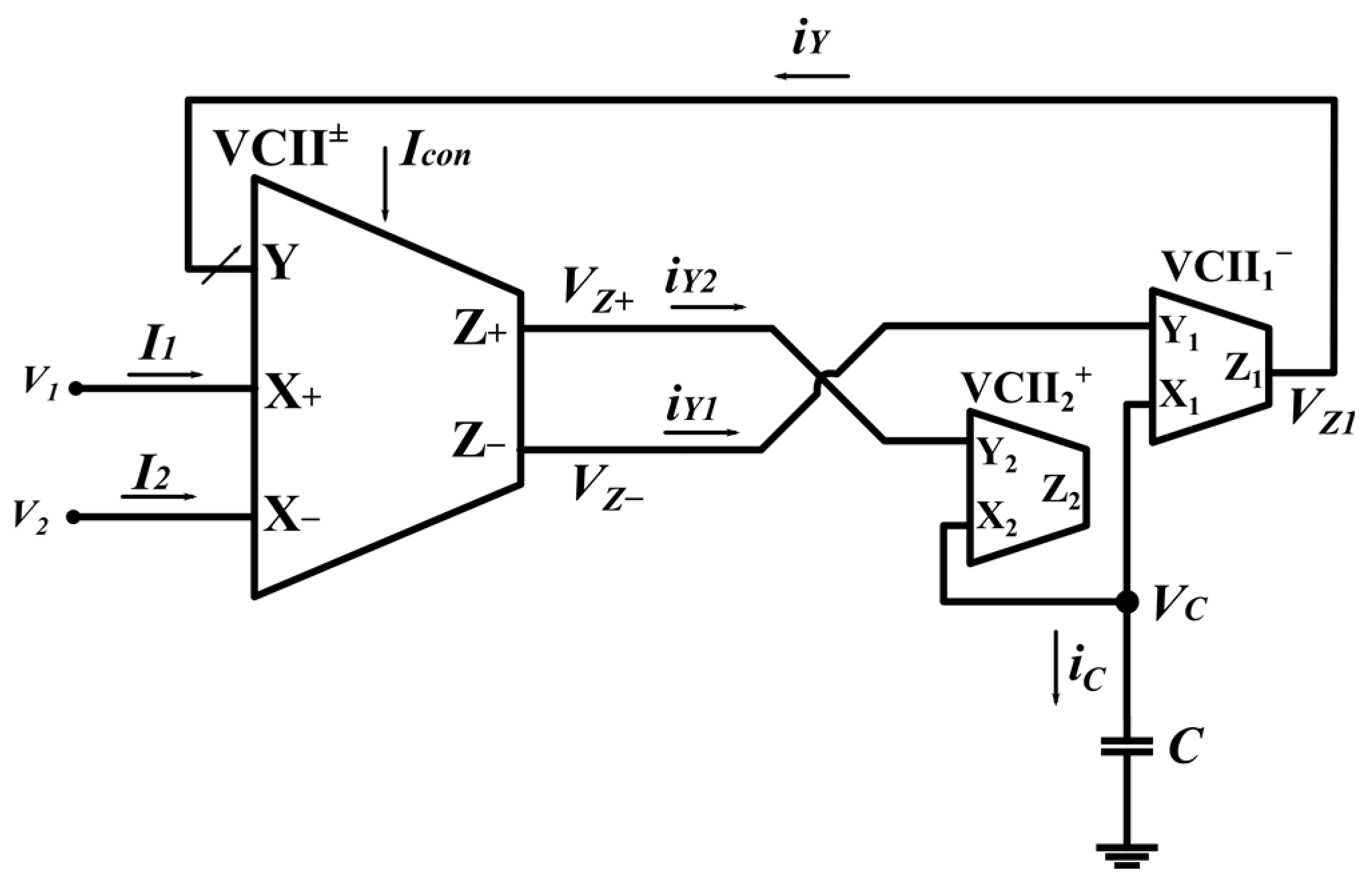
2. The Proposed VCII Based Floating Inductance Simulator
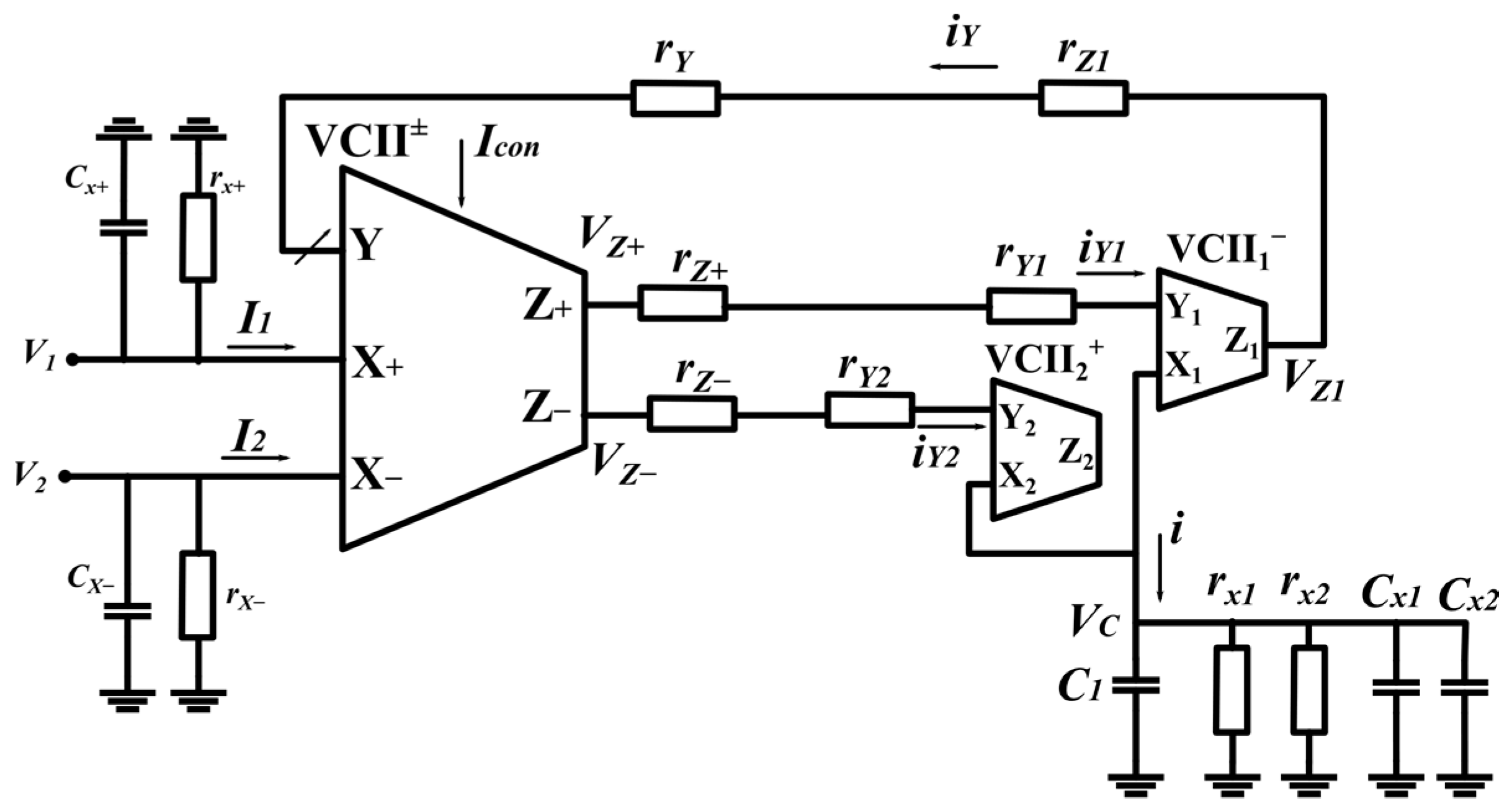
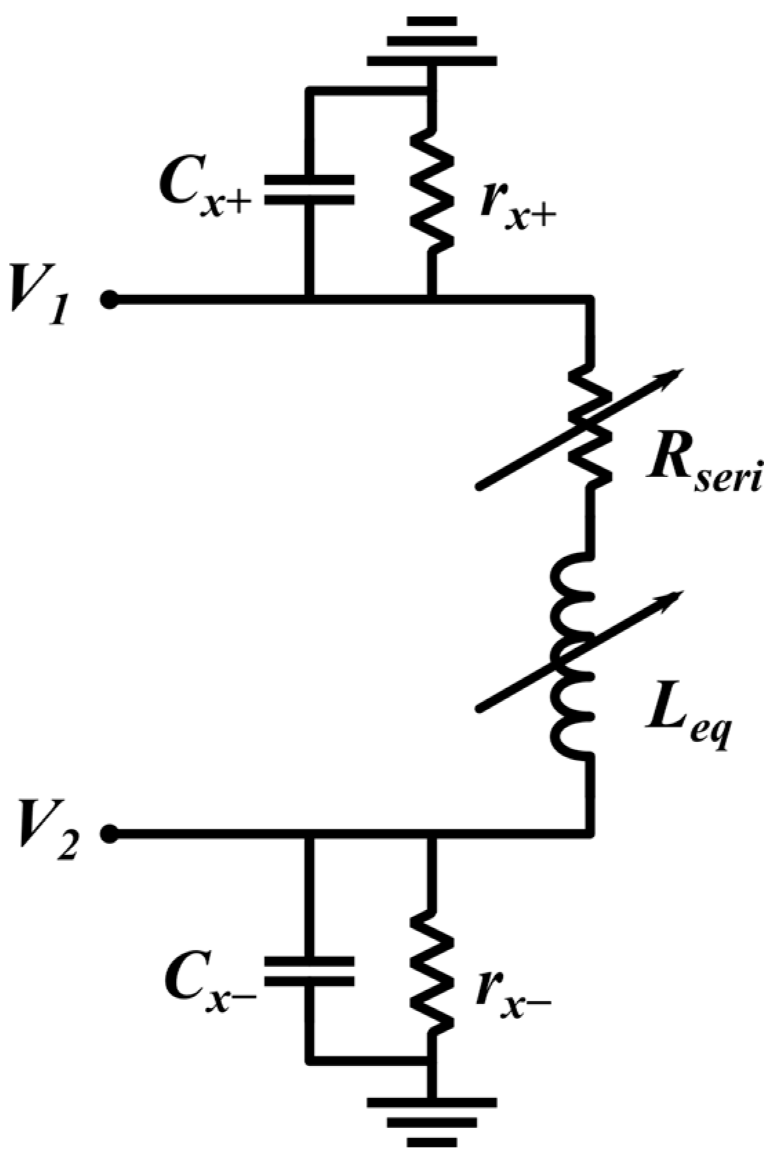
3. Non-Ideal Analysis
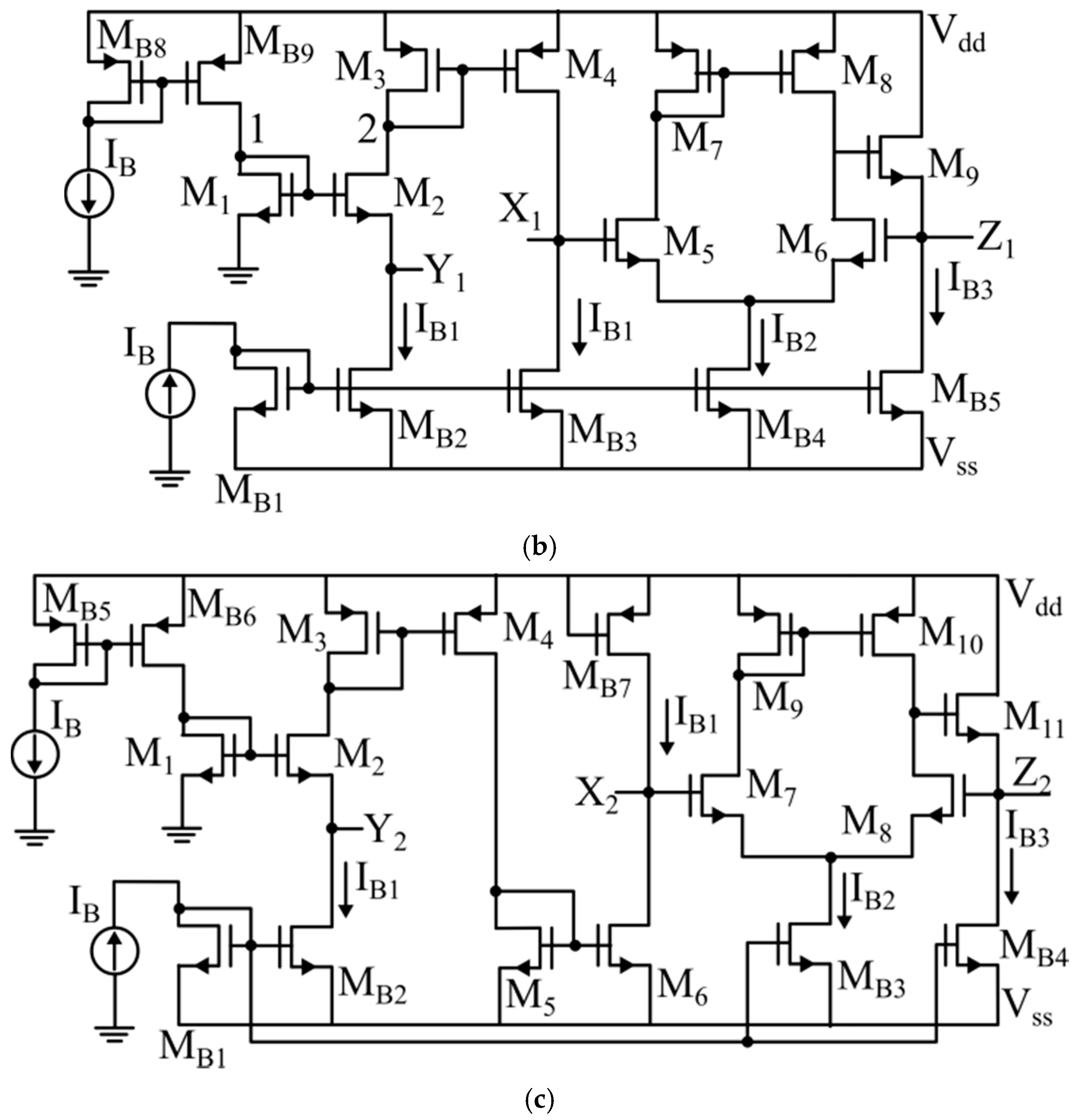
4. CMOS Implementation of VCII
5. Simulation Results
6. Conclusions
Author Contributions
Funding
Data Availability Statement
Conflicts of Interest
References
- Ye, X.; Wang, Y.; Tang, X.-Y.; Ji, H.; Wang, B.; Huang, Z. On the Design of a New Simulated Inductor Using a Contactless Electrical Tomography System as an Example. Sensors 2019, 19, 2463. [Google Scholar] [CrossRef] [Green Version]
- Lyu, Y.; Huang, J.; Huang, Z.; Ji, H.; Wang, B.; Li, H. Study on the application of simulated inductor technique to the design of C4D sensor. Sens. Actuators A Phys. 2017, 264, 195–204. [Google Scholar] [CrossRef]
- Soliman, A. On the realization of floating inductors. Nat. Sci. 2010, 8, 167–180. [Google Scholar]
- Reddy, M. Some new operational-amplifier circuits for the realization of the lossless floating inductance. IEEE Trans. Circuits Syst. 1976, 23, 171–173. [Google Scholar] [CrossRef]
- Said, L.A.; Madian, A.H.; Ismail, M.H.; Soliman, A.M. Digitally programmable lossless floating inductor realization using current differential amplifier (CDA). In Proceedings of the 16th IEEE Mediterranean Electrotechnical Conference, Yasmine Hammamet, Tunisia, 25–28 March 2012; IEEE: Piscataway, NJ, USA, 2012; pp. 840–843. [Google Scholar]
- Said, L.A.; Madian, A.H.; Isamil, M.H.; Soliman, A.M. CMOS digitally programmable lossless floating inductor. In Proceedings of the IEEE International Conference of Electron Devices and Solid-State Circuits (EDSSC), Hong Kong, China, 15–17 December 2010; IEEE: Piscataway, NJ, USA, 2010; pp. 1–4. [Google Scholar]
- Bhaskar, D.R.; Prasad, D.; Singh, A.K. New Grounded and Floating Simulated Inductance Circuits using Current Differencing Transconductance Amplifiers. Radio Eng. 2010, 19, 194–198. [Google Scholar]
- Tangsrirat, W. Floating simulator with a single DVCCTA. Indian J. Eng. Mater. Sci. 2013, 20, 79–86. [Google Scholar]
- Ibrahim, M.A.; Minaei, S.; Yuce, E.; Herencsar, N.; Koton, J. Lossy/lossless floating / grounded inductance simulation using one DDCC. Radioengineering 2012, 21, 3–10. [Google Scholar]
- Zhou, X.; Zeng, R. Floating Inductance Simulators Based on Active Components. DEStech Trans. Eng. Technol. Res. 2017, 1904–1908. [Google Scholar] [CrossRef] [Green Version]
- Lawanwisut, S.; Siripruchyanun, M. An electronically controllable active-only current-mode floating inductance simulator. In Proceedings of the 35th International Conference on Telecommunications and Signal Processing (TSP), Prague, Czech Republic, 3–4 July 2012; IEEE: Piscataway, NJ, USA, 2012; pp. 386–389. [Google Scholar]
- Yuce, E.; Tokat, S.; Alpaslan, H. Grounded capacitor-based new floating inductor simulators and a stability test. Turk. J. Electr. Eng. Comput. Sci. 2015, 23, 2138–2149. [Google Scholar] [CrossRef] [Green Version]
- Likhitkitwoerakul, N.; Roongmuanpha, N.; Tangsrirat, W. Floating Impedance Simulator Realization. In Proceedings of the 17th International Conference on Electrical Engineering/Electronics, Computer, Telecommunications and Information Technology (ECTI-CON), Phuket, Thailand, 24–27 June 2020; IEEE: Piscataway, NJ, USA, 2020; pp. 345–348. [Google Scholar]
- Yuce, E.; Minaei, S. A Modified CFOA and Its Applications to Simulated Inductors, Capacitance Multipliers, and Analog Filters. IEEE Trans. Circuits Syst. I Regul. Pap. 2008, 55, 266–275. [Google Scholar] [CrossRef]
- Al-Absi, M.A. Realization of a Large Values Floating and Tunable Active Inductor. IEEE Access 2019, 7, 42609–42613. [Google Scholar] [CrossRef]
- Čajka, J.; Vrba, K. The Voltage Conveyor May Have in Fact Found its Way into Circuit Theory. AEU Int. J. Electron. Commun. 2004, 58, 244–248. [Google Scholar] [CrossRef]
- Safari, L.; Barile, G.; Stornelli, V.; Ferri, G. An Overview on the Second Generation Voltage Conveyor: Features, Design and Applications. IEEE Trans. Circuits Syst. II Express Briefs 2019, 66, 547–551. [Google Scholar] [CrossRef]
- Safari, L.; Barile, G.; Ferri, G.; Stornelli, V. High performance voltage output filter realizations using second generation voltage conveyor. Int. J. RF Microw. Comput. Aided Eng. 2018, 28, e21534. [Google Scholar] [CrossRef]
- Safari, L.; Barile, G.; Ferri, G.; Stornelli, V. Traditional Op-Amp and new VCII: A comparison on analog circuits applications. AEU Int. J. Electron. Commun. 2019, 110, 152845. [Google Scholar] [CrossRef]
- Safari, L.; Barile, G.; Stornelli, V.; Ferri, G.; Leoni, A. New Current Mode Wheatstone Bridge Topologies with Intrinsic Linearity. In Proceedings of the 14th Conference on Ph.D. Research in Microelectronics and Electronics (PRIME), Prague, Czech Republic, 2–5 July 2018; IEEE: Piscataway, NJ, USA, 2018; pp. 9–12. [Google Scholar]
- Stornelli, V.; Safari, L.; Barile, G.; Ferri, G. A New Extremely Low Power Temperature Insensitive Electronically Tunable VCII-Based Grounded Capacitance Multiplier. IEEE Trans. Circuits Syst. II Express Briefs 2021, 68, 72–76. [Google Scholar] [CrossRef]
- Safari, L.; Yuce, E.; Minaei, S.; Ferri, G.; Stornelli, V. A second-generation voltage conveyor (VCII)–based simulated grounded inductor. Int. J. Circuit Theory Appl. 2020, 48, 1180–1193. [Google Scholar] [CrossRef]


| VCII± | VCII− | VCII+ | ||
|---|---|---|---|---|
| rY | Icon = 0 µA | 3.43 kΩ | 3.43 kΩ | 3.43 kΩ |
| Icon = 25 µA | 2.18 kΩ | |||
| Icon = 50 µA | 1.8 kΩ | |||
| rX | rx+ = 240 kΩ, rx− = 244 kΩ | 240 kΩ | 250 kΩ | |
| rz | rz− = rz+ = 48 Ω | 48 Ω | 48 Ω | |
| α | α+ = α− = 0.981 | 0.981 | 0.981 | |
| β | Icon = 0 µA | β+ = 1.007, β− = 1.04 | 1.042 | 1.002 |
| Icon = 25 µA | β+ = 0.988, β− = 1.03 | |||
| Icon = 50 µA | β+ = 0.999, β− = 1.023 | |||
| Cx | Cx+ = 48 fF, Cx− = 64 fF | 74 fF | 37 fF | |
| Power dissipation | 0.352–0.625 mW | 0.242 mW | 0.201 mW | |
| Icon | Calc. Rseri | Sim. Rseri | Calc. Leq | Sim. Leq | % of Error in Leq | |
|---|---|---|---|---|---|---|
| Negative simulator | 0 | 97 Ω | 76 Ω | 588 µH | −576 µH | −2% |
| 25 µA | 61 Ω | 50.2 Ω | 374 µH | −382 µH | 2.1% | |
| 50 µA | 51 Ω | 43 Ω | 309 µH | −324 µH | 4.8% | |
| Positive simulator | 0 | 97 Ω | 76 Ω | 588 µH | 576 µH | −2% |
| 25 µA | 61 Ω | 49 Ω | 374 µH | 366 µH | −2.9% | |
| 50 µA | 51 Ω | 42 Ω | 309 µH | 316 µH | 2.3% |
| Parameter | P | V (Vdd-Vss) | T (°C) | |||||||
|---|---|---|---|---|---|---|---|---|---|---|
| FF | SF | FS | SS | ±0.99 V | ±0.81 V | −20 | 25 | 80 | ||
| rY (Ω) | Icon = 0 µA | 3.36 k | 3.41 k | 3.416 k | 3.5 k | 3.395 k | 3.462 k | 2.985 k | 3.45 k | 3.944 k |
| Icon = 25 µA | 2.21 k | 2.16 k | 2.168 k | 2.2 k | 2.18 k | 2.22 k | 1.87 k | 2.16 k | 2.52 k | |
| Icon = 50 µA | 1.75 k | 1.78 k | 1.79 k | 1.81 k | 1.76 k | 1.86 k | 1.52 k | 1.77 k | 2.11 k | |
| [rX+, rX−] kΩ | [238, 205] | [243, 132] | [240, 243] | [245, 242] | [225, 242] | [242, 248] | [200.1, 200] | [242, 239] | [249, 287.4] | |
| rZ+ = rz− (Ω) | 45 | 47.6 | 45 | 49 | 51 | 54 | 54 | 47.6 | 50.2 | |
| α+ = α− | 0.981 | 0.980 | 0.990 | 0.980 | 0.982 | 0.978 | 0.980 | 0.981 | 0.980 | |
| β+, β− | Icon = 0 µA | 1.01, 1.047 | 1.01, 1.046 | 0.993, 1.029 | 1.004, 1.026 | 1.009, 1.057 | 1.011, 1.065 | 1.018, 1.066 | 1.01, 1.047 | 1.005, 1.03 |
| Icon = 25 µA | 1, 1.038 | 1, 1.036 | 1, 1.0368 | 0.999, 1.035 | 1.006, 1.046 | 1.056, 1.006 | 1.006, 1.055 | 1, 1.037 | 0.995, 1.021 | |
| Icon = 50 µA | 0.993, 1.031 | 0.993, 1.029 | 0.993, 0.980 | 0.992, 1.028 | 0.999, 1.049 | 0.997, 1.009 | 0.999, 1.047 | 0.993, 1.03 | 0.988, 1.015 | |
| Cx+, Cx− (fF) | 49, 80 | 59, 81 | 61, 77 | 58, 64 | 59, 119 | 34, 60 | 92, 94 | 61, 77 | 68, 81 | |
| Power Dissipation (µW) | 313–583 | 353–625 | 317–605 | 313–625 | 332–657 | 313–553 | 356–630 | 353–625 | 350–620 | |
| Parameter | P | V (Vdd-Vss) | T (°C) | ||||||
|---|---|---|---|---|---|---|---|---|---|
| FF | SF | FS | SS | ±0.99 V | ±0.81 V | −20 | 25 | 80 | |
| rY | 3.38 kΩ | 3.43 kΩ | 3.44 kΩ | 3.49 kΩ | 3.4 kΩ | 3.5 kΩ | 3 kΩ | 3.4 kΩ | 4 kΩ |
| rX | 250 kΩ | 250 kΩ | 250.3 kΩ | 252.6 kΩ | 250 kΩ | 251 kΩ | 205 kΩ | 249 kΩ | 302 kΩ |
| rZ | 46 Ω | 47 Ω | 47.1 Ω | 48.4 Ω | 50 Ω | 88 Ω | 43 Ω | 54 Ω | 72 Ω |
| α | 0.981 | 0.981 | 0.984 | 0.983 | 0.986 | 0.978 | 0.980 | 0.973 | 0.974 |
| β | 1.0026 | 1.0023 | 1.0023 | 0.9966 | 1.008 | 0.996 | 1.008 | 0.996 | 0.993 |
| cx | 32 fF | 41 fF | 38 fF | 38.1 fF | 32 fF | 37 fF | 37 fF | 39 fF | 40 fF |
| Power dissipation | 202 µW | 203 µW | 202 µW | 201 µW | 224 µW | 186 µW | 204 µW | 203 µW | 202 µW |
| Parameter | P | V (Vdd-Vss) | T (°C) | ||||||
|---|---|---|---|---|---|---|---|---|---|
| FF | SF | FS | SS | ±0.99 V | ±0.81 V | −20 | 25 | 80 | |
| rY | 3.36 kΩ | 3.41 kΩ | 3.41 kΩ | 3.46 kΩ | 3.39 kΩ | 3.46 kΩ | 2.97 kΩ | 3.4 kΩ | 3.94 kΩ |
| rX (kΩ) | 211 kΩ | 212 k Ω | 212.5 kΩ | 214 kΩ | 199 kΩ | 223 kΩ | 178.44 kΩ | 206.3 kΩ | 252 kΩ |
| rZ (Ω) | 46.5 Ω | 47.7 Ω | 47.6 Ω | 49 Ω | 46.2 Ω | 52.5 Ω | 42 Ω | 46 Ω | 54 Ω |
| α | 0.981 | 0.980 | 0.984 | 0.980 | 0.986 | 0.976 | 0.980 | 0.980 | 0.980 |
| β | 1.048 | 1.046 | 1.046 | 1.045 | 1.0665 | 1.027 | 1.066 | 1.047 | 1.038 |
| cx | 110 fF | 112 fF | 115 fF | 110 fF | 119 fF | 130 fF | 107 fF | 113 fF | 115 fF |
| Power dissipation | 190 µW | 200 µW | 190 µW | 190 µW | 228 µW | 187 µW | 191 µW | 190 µW | 189 µW |
| +Leq (µH) | −Leq (µH) | ||||||||||||||||||
|---|---|---|---|---|---|---|---|---|---|---|---|---|---|---|---|---|---|---|---|
| Icon = 0 µA | Icon = 25 µA | Icon = 50 µA | Icon = 0 µA | Icon = 25 µA | Icon = 50 µA | ||||||||||||||
| S. 1 | C. 2 | E 3 (%) | S. | C. | E (%) | S. | C. | E (%) | S. | C. | E (%) | S. | C. | E (%) | S. | C. | E (%) | ||
| P | FF | 538 | 580 | −7.2 | 360 | 382 | −5.7 | 309 | 311 | −0.6 | 539 | 583 | −7.5 | 361 | 378 | −4.5 | 310 | 312 | −0.64 |
| SF | 571 | 597 | −4.3 | 379 | 341 | +11 | 323 | 316 | +2.2 | 573 | 601 | −4.6 | 378 | 384 | −1.5 | 324 | 318 | +1.9 | |
| FS | 571 | 597 | −4.3 | 379 | 342 | +11 | 324 | 323 | +0.3 | 572 | 603 | −5.1 | 378 | 386 | −2 | 323 | 320 | +1 | |
| SS | 605 | 622 | −2.7 | 396 | 389 | +1.8 | 338 | 320 | +5.6 | 606 | 628 | −3.5 | 396 | 400 | −1 | 338 | 329 | +2.7 | |
| V (V) | ±0.99 | 523 | 591 | −11.5 | 362 | 383 | −5.4 | 317 | 314 | +1 | 484 | 591 | −11.5 | 362 | 390 | −7.1 | 317 | 312 | +1.6 |
| ±0.81 | 566 | 606 | −6 | 385 | 392 | −1.8 | 338 | 318 | +6.2 | 563 | 624 | −9.8 | 385 | 404 | −4.7 | 338 | 340 | −0.6 | |
| T (°C) | −20 | 428 | 458 | −6.5 | 307 | 289 | +6.2 | 234 | 236 | −0.8 | 423 | 462 | −8.4 | 307 | 292 | +5.2 | 234 | 239 | −2 |
| 25 | 568 | 602 | −5.6 | 356 | 380 | −6.3 | 308 | 313 | −1.6 | 569 | 603 | −5.6 | 357 | 380 | −6 | 306 | 313 | −1 | |
| 80 | 877 | 797 | +10 | 483 | 513 | −5.8 | 423 | 432 | −2 | 879 | 810 | +8 | 483 | 521 | −7.3 | 423 | 438 | +3.4 | |
| +Leq (µH) | −Leq (µH) | ||||||||
|---|---|---|---|---|---|---|---|---|---|
| Max | Min | Mean | Typical | Max | Min | Mean | Typical | ||
| Icon | 0 µA | 1221 | 453 | 672 | 576 | 1710 | 459 | 749 | 576 |
| 25 µA | 580 | 362 | 427 | 366 | 529 | 359 | 416 | 389 | |
| 50 µA | 500 | 316 | 355 | 316 | 431 | 315 | 349 | 324 | |
| Ref. | Frequency Range | +L/−L | Vdd-Vss | Tuning | #R | #Float. C | ABB |
|---|---|---|---|---|---|---|---|
| [5] | NA | +L | NA | Digital | 5 | 2CDA | |
| [6] | NA | +L | ±1.5 V | Digital | 10 | 0 | 4CCII |
| [7] | 1 Hz–1 MHz | +L | ±2.5 V | Yes | 0 | 3CDTA | |
| [8] | 100 kHz–10 MHz | +L | ±2 V | Yes | 1 | 0 | 1DVCCTA |
| [9] | 10 kHz–400 kHz | +L | ±1.5 V | No | 2 | 0 | 1DO DDCC |
| [10] | NA | +L | ±1.25 V | Yes | 1 | 1 | 1DVCC 1CCCII 1 1Gm 1CCCII 2 |
| [11] | NA | +L | ±5 V | Yes | 0 | 0 | 1CCCCTA OA |
| [12] | 1 kHz–10 MHz | +L | ±0.75 V | No | 2 | 0 | 2DTVC |
| [13] | <10 MHz | +L | ±0.75 V | No | 2 | 0 | 2DDCC |
| [14] | 10 kHz–10 MHz | +L | ±1.5 V | No | 2 | 0 | 2MCFOA |
| [15] | NA | +L | NA | No | 1 | 1 | 1CCII± 1DO OTA |
| this | 0.1–3 MHz | L± | ±0.9 V | Yes | 0 | 0 | 1VCII± 1VCII+ VCII− |
Publisher’s Note: MDPI stays neutral with regard to jurisdictional claims in published maps and institutional affiliations. |
© 2022 by the authors. Licensee MDPI, Basel, Switzerland. This article is an open access article distributed under the terms and conditions of the Creative Commons Attribution (CC BY) license (https://creativecommons.org/licenses/by/4.0/).
Share and Cite
Safari, L.; Barile, G.; Colaiuda, D.; Stornelli, V.; Ferri, G. Realization of an Electronically Tunable Resistor-Less Floating Inductance Simulator Using VCII. Electronics 2022, 11, 312. https://doi.org/10.3390/electronics11030312
Safari L, Barile G, Colaiuda D, Stornelli V, Ferri G. Realization of an Electronically Tunable Resistor-Less Floating Inductance Simulator Using VCII. Electronics. 2022; 11(3):312. https://doi.org/10.3390/electronics11030312
Chicago/Turabian StyleSafari, Leila, Gianluca Barile, Davide Colaiuda, Vincenzo Stornelli, and Giuseppe Ferri. 2022. "Realization of an Electronically Tunable Resistor-Less Floating Inductance Simulator Using VCII" Electronics 11, no. 3: 312. https://doi.org/10.3390/electronics11030312
APA StyleSafari, L., Barile, G., Colaiuda, D., Stornelli, V., & Ferri, G. (2022). Realization of an Electronically Tunable Resistor-Less Floating Inductance Simulator Using VCII. Electronics, 11(3), 312. https://doi.org/10.3390/electronics11030312