Article

Energy Efficient Distance Computing: Application to K-Means Clustering

School of Electrical and Electronics Engineering, Chung-Ang University, Seoul 06974, Korea
*
Author to whom correspondence should be addressed.
Electronics 2022, 11(3), 298; https://doi.org/10.3390/electronics11030298
Submission received: 1 December 2021 / Revised: 10 January 2022 / Accepted: 11 January 2022 / Published: 18 January 2022
(This article belongs to the Section Circuit and Signal Processing)

Abstract

:
Distance computation between two input vectors is a widely used computing unit in several pattern recognition, signal processing and neuromorphic applications. However, the implementation of such a functionality in conventional CMOS design requires expensive hardware and involves significant power consumption. Even power-efficient current-mode analog designs have proved to be slower and vulnerable to variations. In this paper, we propose an approximate mixed-signal design for the distance computing core by noting the fact that a vast majority of the signal processing applications involving this operation are resilient to small approximations in the distance computation. The proposed mixed-signal design is able to interface with external digital CMOS logic and simultaneously exhibit fast operating speeds. Another important feature of the proposed design is that the computing core is able to compute two variants of the distance metric, namely the (i) Euclidean distance squared ( L 2 2 norm) and (ii) Manhattan distance ( L 1 norm). The performance of the proposed design was evaluated on a standard K-means clustering algorithm on the “Iris flower dataset”. The results indicate a throughput of 6 ns per classification and ∼2.3× lower energy consumption in comparison to a synthesized digital CMOS design in commercial 45 nm CMOS technology.

1. Introduction

With the increasing demand for image and signal processing tasks that need to be routinely performed in present-day mobile devices, power and energy-efficient custom hardware implementations are becoming indispensable. This study focuses on the distance calculation metric between two multidimensional vectors. As a specific example, we will consider the application of this metric to K-means clustering algorithms, one of the simplest clustering methods commonly used in various areas, such as artificial intelligence [1], pattern recognition [2,3] and image segmentation [4,5]. Until recently, the K-means algorithm is still used for solving more complex and sophisticated problems through continuous improvement [6].
In addition to the possible applications mentioned above that can utilize the K-means clustering algorithm, theoretical studies have recently been proposed to improve the clustering algorithm itself based on improved distance metrics, such as adaptive fused distance [7] and S-distance [8]. Furthermore, instead of relying on a simple similarity measure (such as Euclidean distance) to divide the dataset into different groups, a study of an advanced similarity measure to identify hidden patterns in data based on Jeffrey-differences was proposed in [9,10].
However, despite the theoretical study and application of K-means clustering, efficient hardware implementation does not appear to have yet been achieved despite the simple and repetitive multiplication and addition operations required for distance calculation. Apart from the most intuitive approach to implementing clustering algorithms based on digital logic gates, various distance computing methods using analog [11,12,13,14,15] and mixed-mode design [16,17] have been proposed in the literature. As is well known, the digital-based approach can provide the most accurate and fast operating speed at the cost of area and power, while analog methods have comparable precision characteristics despite their simple structure.
Although accurate distance computation is an important requirement in many cases, there are some applications that can tolerate small errors in distance measurement results. For example, in K-means cluster analysis, inputs are classified based on the minimum distance between the input and the cluster center. Therefore, determining the correct cluster with the minimum distance is more important than calculating the distance numerically accurate [18,19]. This resilience to small errors can lead us to utilize approximate computing for energy-efficient distance calculation unit design. In this context, analog current mode computing can be a promising candidate for our goals with essentially simple structures and approximate computational characteristics. However, vulnerability to environmental changes and slow operation speed are the main drawbacks of this approach. To overcome this, an approximate distance calculation core based on mixed-mode design is proposed to achieve both the fast operating speed and comparable accuracy.
The basic motivation for the proposed distance calculation unit begins with constructing an approximate multiplier, a hardware costly part of distance computation. This multiplication can be performed approximately by filling the capacitor using a constant current source for a certain period of time. The voltage of the capacitor is then proportional to the product of the current and the charging time. Therefore, if two inputs to the multiplier can be controlled separately, the corresponding output voltage obtained from the capacitor represents the multiplication output.
Following the above discussion, here, we propose K-means clustering hardware based on an energy-efficient distance computing core. The main contributions of the proposed research are as follows: (1) A mixed-signal approximate distance calculation core capable of calculating the Manhattan distance or Euclidean distance square between two multidimensional vectors was proposed. (2) It has been successfully shown that the proposed distance computing unit can be exploited in K-means clustering hardware based on a circuit-application co-simulation framework.
The rest of the article is organized as follows. Section 2 addresses related works in similar fields. Section 3 provides a brief overview of the basics of approximate distance calculation. Details of the proposed distance computation unit and its operation are discussed in Section 4. The overall structure of the K-means clustering module based on the approximate distance calculation device and the simulation framework are presented in Section 5. Section 6 presents clustering results using the Iris flower dataset and performance analysis of the proposed system. Section 7 concludes the article.

2. Related Works

This section will introduce some of the previous works devoted to developing hardware implementations of distance computation units. Before starting, it would be good to mention some basic operations that need to be performed by the core computing unit for distance calculation. The purpose of distance calculation is to find the difference between the two multidimensional vectors and then the sum of the absolute values (Manhattan distance metric, L 1 norm) or the sum of the squares of the differences (Euclidean distance square metric, L 2 2 norm). Accordingly, the distance calculation unit basically needs to perform subtraction between two input multidimensional vectors first. Then, the absolute value of the subtraction result for each sub-element needs to be added for L 1 distance, or the sum of the squares of each sub-element is required for L 2 2 distance.
The authors of [18,19] propose an analog distance computing core that utilizes current mode calculation for most of the main functions required for distance computation. For instance, the current-mode operation was used to (1) subtract between two multidimensional vectors, (2) take the absolve value, (3) calculate the square of each term, and then (4) add all of each term. This analog method can provide reasonably good accuracy if each component of the analog circuit is ensured to operate under appropriate operating conditions. In addition, due to the simple current mode operation based on Kirchhoff’s law, the entire structure may consist of a minimum number of transistors compared to the other methods introduced in the next paragraphs. However, the current mode operation is assumed to be very vulnerable to environmental changes, and it generally takes too much time to obtain a final answer.
Instead of using the full analog implementation of the distance calculation core, a mixed-signal approach was proposed in [17,20] to find the minimum distance. Here, some of the calculations are performed in the digital domain, and the remaining calculations are performed in the analog domain. Note that the target application in references [17,20] is associated memory. It is still very similar to the application under consideration because the goal is to find data with a minimum distance from the presented input data among the data stored inside the memory. Due to the binary data stored in memory, the initial part of the distance computation was implemented by digital subtraction based on the adder or XOR function. However, the latter portion still relies on the current mode squarer [20] or the neuron CMOS inverter-based computation [17]. Although the speed of the distance calculation could have improved somewhat due to the initial digital part, the overall computational time is still comparable to the analog counterpart because the main square function is still performed in the analog domain.
Apart from the aforementioned two analog and mixed signal-based calculations, a fully digital-based distance computation approach has been proposed in [21,22]. Instead of faithfully implementing digital components for subtraction, generation of absolute values, square functions, and addition, the authors of [21,22] propose the concept of distance-clock-mapping to calculate the Euclidean distance between the two input vectors. The key idea proposed in these pieces of research is to calculate the square distance corresponding to one element of a multidimensional input vector at a time, then repeat the calculation and accumulate the resulting value to obtain the final distance value. This method effectively reduced the silicon area compared to the area consumed by the full precision multiplier and adder. In addition, it is possible to generate the most accurate distance calculation if the implemented hardware can support full precision of data. However, there are still opportunities to approximate distance calculations depending on the target application that can significantly improve the efficiency of overall system operation.
Based on the discussion in this section, we proposed an efficient distance computing core based on the mixed-signal approach introduced in [20]. However, instead of utilizing the current-mode square unit, we have proposed a concise and fast square computation unit based on the simple fact that the voltage across the capacitor is proportional to the product of (1) the amount of applied current pulse and (2) time duration. In addition, the output of the L 2 2 unit becomes a voltage level, which helps to cluster a given input based on the minimum distance using a simple latch-based voltage comparator.

3. Basic Distance Metrics

Conventionally, L 1 and L 2 2 norms are used to measure the distance between two multi-dimension vectors. For two n-dimensional vectors (x and c), the L 1 and L 2 2 norm can be described as follows:
D L 1 = i = 1 n | x i c i | .
D L 2 2 = i = 1 n ( x i c i ) 2 .
As shown in the above formulae, the computation of distance between two input vectors, especially the L 2 2 norm, requires multiplication (squaring) and addition operations. In order to implement this functionality in hardware, the number of multiplications and additions required is equivalent to the number of dimensions (n) of the input vector. Further, the K-means clustering algorithm requires the computation of such a distance metric for a large number of input vectors over a number of epochs, thereby resulting in significant area, power and energy overheads. However, applications in signal processing that utilize such distance metrics are usually resilient to slight approximations in the metric value. Hence, optimizations can be performed by constraining the number of bits used to represent the two input vectors. For example, simulation studies for K-means clustering on the “Iris flower dataset” [23] reveal that there is insignificant degradation in the final clustering result when 5 bits are utilized for the input vectors. However, even with such optimizations, digital CMOS implementations still involve significant energy consumption (explained in the next section), thereby providing motivation for the exploration of alternative design approaches.

Proposed Approximate Distance Computing Unit

As discussed earlier, the basic computational units for the distance metric are multiplication and addition. However, in order to implement the multiplication operation in digital CMOS technology with 5-bit input vector resolution, at least 25 Full Adders are required for each multiplier. Further, the final addition operation after the multiplication step requires twice the number of bits of the input vector (as it is driven by multiplier outputs). Since this operation is performed iteratively over a large number of input vectors, alternative implementations involving analog current-mode designs of such computations are being actively explored [11,12,14]. The main advantage of this approach results from the fact that the addition/subtraction operation can be mapped to current flowing into/out of a circuit node (following Kirchhoff’s current law). However, such approaches suffer from high latency and are highly prone to PVT changes. In this work, we propose a mixed signal design for the distance computing unit to address the above limitations. The inspiration behind our approach arises from the fact that the voltage V across a capacitor C being charged by a constant current source i for an integration time t is proportional to the input current multiplied by the integration time as follows:
V = ( i t ) / C .
Figure 1 illustrates the basic idea. Figure 1a depicts that the output voltage follows a linear trend ( L 1 norm) when the integration time ( t 1 t 3 ) varies linearly and the input current is kept constant at i f i x . On the other hand, the output voltage in Figure 1b varies in a quadratic fashion ( L 2 2 norm) when the integration time ( t 1 t 3 ) and input current ( i 1 i 3 ) are incremented concurrently. This is the principal motivation for the proposed design of computing L 1 and L 2 2 norms. In order to implement the concept into CMOS hardware, three components are required, as shown in Figure 2a. They are as follows: (1) the circuit to control the input current i, (2) switches to control the integration time t, and (3) the output capacitance C. The actual implementation of Figure 2a is depicted in Figure 2b. In order to interface the computing block with external digital CMOS circuitry, a binary weighted current mode Digital-to-Analog Converter (I-DAC) with 5-bit resolution was utilized. To turn on/off each current path selectively, each transistor (1×∼16×) is provided with a corresponding switch. Hence, the upper row of the stacked transistors in Figure 2b controls the amount of input current to the capacitor, and the lower row controls the integration time corresponding to the magnitude of the inputs. Based on this design, we can generate both of the L 1 and L 2 2 norms, as shown in Figure 1.

4. Circuit Details for the Distance Computing Unit

This section outlines the details of each circuit component constituting the approximate distance computing unit and their operations. Furthermore, we will demonstrate the generation of L 1 and L 2 2 norms from the proposed design, which will be utilized subsequently for K-means clustering algorithm.

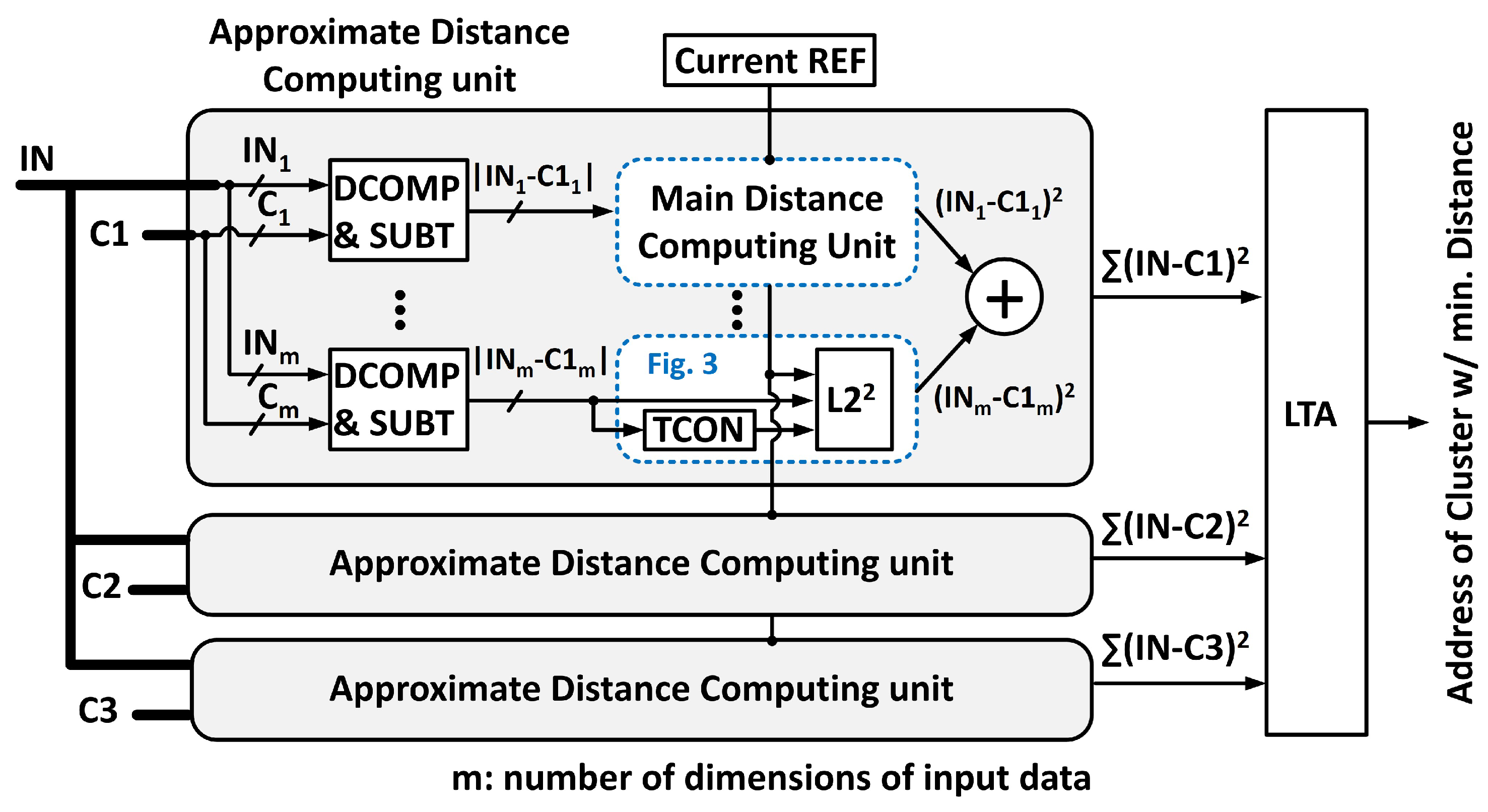
4.1. Main Distance Computing Unit

The complete design of the approximate multiplier proposed in the previous section with peripherals is illustrated in Figure 3. The individual components are: (1) current reference circuit to provide a bias voltage V B I A S to the current-mode DAC, (2) Timing controller to control the integration time proportional to the magnitude of the input vector, and (3) Path selector to turn on/off the proper current path depending on the input vector. Let us now discuss the operation of the approximate multiplication unit. Assuming the input to the multiplier unit is the absolute difference between two inputs A and B, a low-active pulse is generated whose width is proportional to the magnitude | A B | using the timing controller. The same input vector also selects a proper current path to the capacitor by forcing the outputs of the AND gate to low level appropriately. Hence, the input current magnitude to the capacitor is modulated depending on the value of | A B | by the current mode DAC. The time of integration is also modulated by ensuring that the output of the AND gates are low for a time duration proportional to the magnitude of | A B | . For instance, Figure 3 demonstrates the operation of the circuit for the case when the input | A B | is ‘01101’. Since both the input current and integration time are modulated depending on the difference magnitude, the output voltage will be proportional to the square of the input. On the other hand, if the input vector controls only one variable between I D C and the integration time, the output voltage will vary linearly with the input.

4.2. Timing Controller

The main function of the Timing controller in Figure 3 is Pulse Width Modulation (PWM), such that the output pulse width varies in accordance to the magnitude of the input. This can be achieved by providing the clock signal as input to an inverter chain and subsequently combining any of the two outputs from the inverter chain appropriately to form an output pulse with varying width. However, such a circuit involves significantly high switching power and area overhead. Hence, rather than utilizing such a conventional digital design, we propose a clock-less PWM circuit by utilizing the time constant of a discharging R C circuit path to control the pulse width. Figure 4a demonstrates the circuit details for the PWM unit. Initially, the capacitor becomes charged to the V D D level through the P1 transistor during the precharge mode. Then, during the discharge phase, the current I D I S flows through the series path of N 1 transistor, and the resistor and the speed of discharging is dictated by the R C time constant of the circuit. In order to control the discharging speed in a linear fashion, a resistor ladder with five resistors was used. The size of the resistors were increased in a binary weighted manner, such that the timing controller provided 31 steps of delay with a 5-bit resolution. Figure 4b,c depicts the details of the proposed PWM unit and its timing diagram, respectively. The output pulse with varying width is generated by connecting an inverter to the V C A P node. Once the decaying voltage at the V C A P node becomes lower than the threshold voltage ( V t h ) of the inverter, the output of the inverter V 1 will toggle to a high voltage level. Since the slope of the decaying signal at the V C A P node could be altered by changing the resistance value, the signal transition at the V 1 node will also vary. Hence, the pulse width at the output can be modulated by combining the precharge and inverted V 1 signals. The increment of pulse width per 1-bit increment in the input code (Delay Δ /bit) is shown in Figure 4d. The amount of delay increases by almost 50 ps per step throughout the whole input code range, which enables a reasonably linear operation of the proposed multiplication unit.

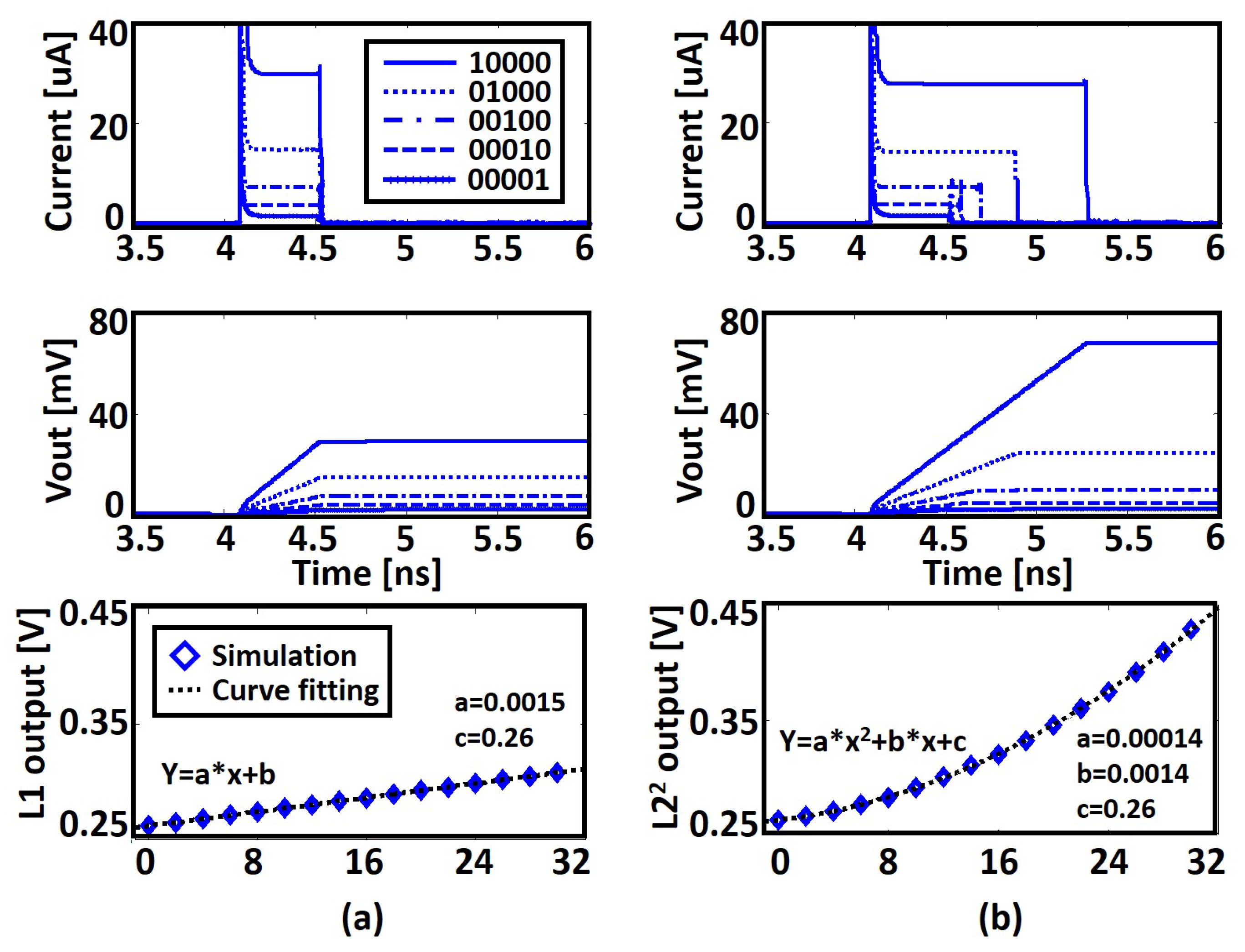
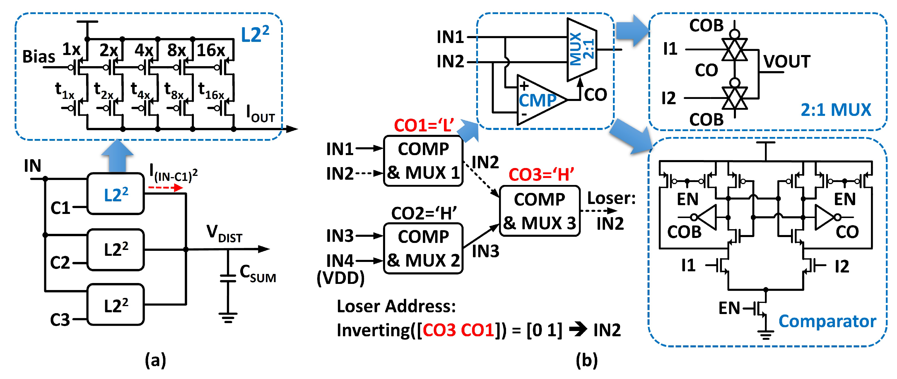
4.3. Generation of Distance Norms

Figure 5 illustrates the current and voltage outputs along with the plots of the two norms obtained from the approximate multiplier with two different input sets. In the case of Figure 5a, the 5-bit input vector only controls the amount of input current (fixed integration time 0.5 ns). For explanation, five input examples are shown in Figure 5 (1, 2, 4, 8, and 16 in decimal). As can be seen, the input current to the capacitor is proportional to the magnitude of the input vector, and the output voltage of the capacitor rises linearly with time. On the other hand, Figure 5b demonstrates the case when both the input current and integration time are modulated by the magnitude of the input. In this case, the final output voltage shows a quadratic variation since the integrator output is determined by the area under the current plot, which is the multiplication of the current magnitude and integration time.

5. Application to K-Means Clustering

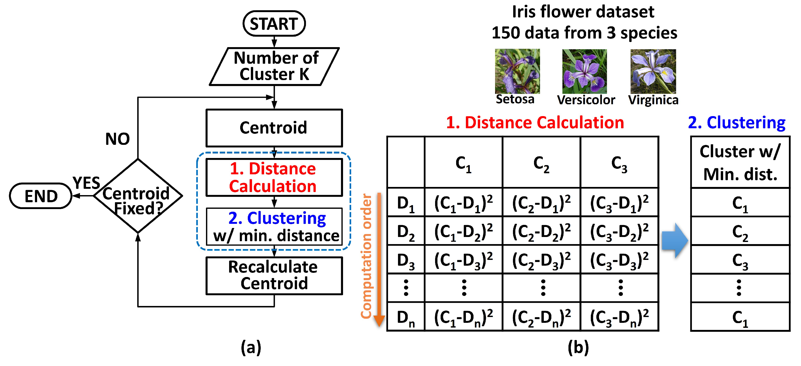
5.1. General K-Means Clustering Algorithm for Iris Dataset

The K-means clustering algorithm involves the iteration of two main processes, namely distance computation and clustering based on the minimum distance. The flowchart of the algorithm is depicted in Figure 6a. The processes involved are: (1) generation of centroids, (2) distance computation of data-points D 1 , , D n from each of the cluster centroids and the generation of distance table, (3) clustering based on minimum distance, and (4) recalculation of centroids. The main computationally expensive portion of these steps involve the distance computation and clustering processes (implemented using multipliers, adders and comparators). The analysis performed in this paper is based on the Iris flower dataset, which includes 150 data from three species of flowers. Each data-point is associated with four dimensions (width/length of sepal and petal).

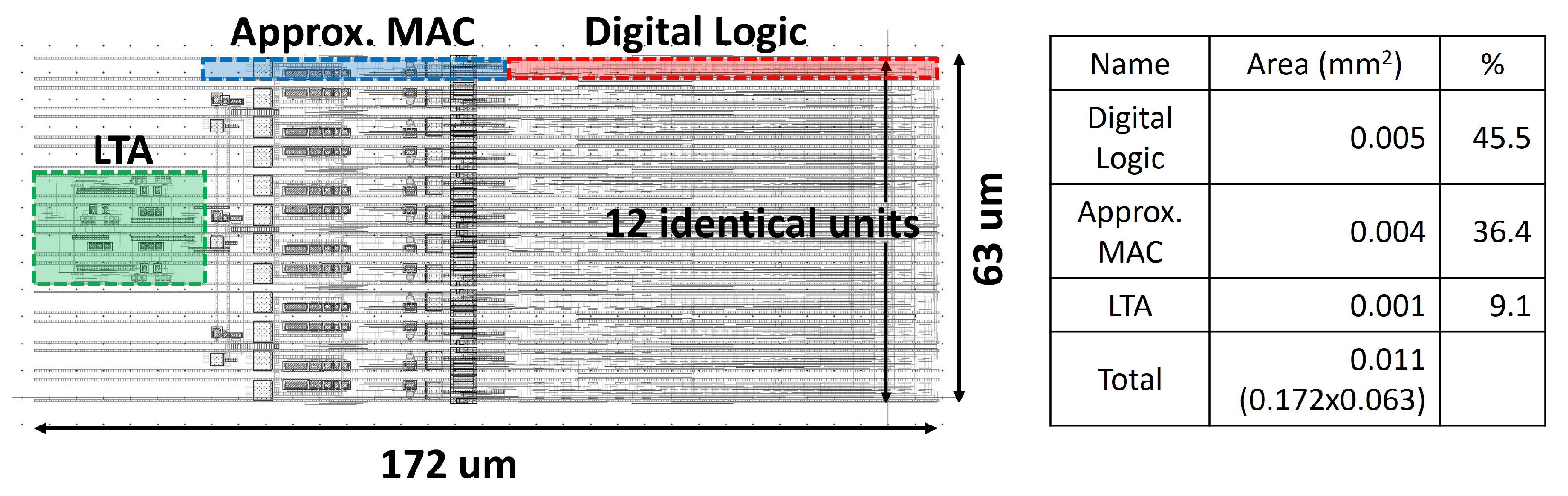
5.2. Architecture of the Proposed K-Means Clustering Unit

The top level architecture of the K-means clustering module is shown in Figure 7. The main distance computing unit (denoted by the dotted box) represents the prime computing unit of the system. The additional circuits are required for the clustering purpose and data pre-processing to compute the absolute difference between the two input vectors. The number of “Approximate Distance Computing Units” in Figure 7 is equal to the number of clusters (three in our example). Each of these distance computing units receives two inputs (in digital format), one of them being a single data-point from the 150 data-points and the other being the centroid value of each cluster. A digital comparator and subtractor unit computes the absolute difference between the two inputs. It is worth noting here that current-mode analog computing is also a popular mechanism to calculate the absolute difference between two inputs [11,12,14]. However, in that case, the inputs should be represented by analog voltages or currents, which require additional converting units to interface with external digital logic. Additionally, it typically requires a longer computing time. To cope with these penalties, pure digital logic-based comparator and subtractor units are used in this work.
After generating the absolute difference, output digital bits are provided as input to the “Main Distance Computing Unit” (described in details in Section 3). The output voltage of each such unit will be proportional to the square of the input (absolute difference). Inside each of the single “Approximate Distance Computing Units”, there are four sets of “Main Distance Computing Unit” cells since the dataset we are considering has four dimensions per input. Therefore, in order to compute the total distance between the input and the centroid, an adder summing up all the L 2 2 norms is required. After the calculation of the total distance between the input vector and the centroids, clustering of the input vector is performed based on the minimum distance approach. For this, we adopted a Loser-Take-All (LTA) circuit. The LTA unit receives the distance values from each “Approximate Distance Computing Unit” and determines the minimum distance value. The output of the LTA is the digital address of the “loser”. It is worth noting here that the input and output of the entire system are digital bits, thereby facilitating communication with conventional digital CMOS logic-based system.

5.3. Additional Circuitry

In this section, we will describe two additional circuits required at the last stage of the K-means clustering module, namely the summation and LTA units. The summer is required to add up the distance contributions from each of the L 2 2 units to generate a resultant distance between the two inputs. In our mixed mode approach for distance computation, addition can be easily performed since the output from the L 2 2 unit is an analog current. Hence, by connecting all the outputs from the L 2 2 units to a single capacitor, the summation can be performed at the junction without any additional circuitry (Figure 8a). Figure 8b demonstrates the block diagram of the LTA unit comprising of 2:1 multiplexers (MUXs) and comparators (COMPs). The inputs to the LTA are analog voltages from each “Approximate Distance Computing Unit”. To define a loser with a short latency, a cell-based tree topology has been used here [24]. Once two input voltages are received by an unit cell of the LTA, the comparator determines the smaller input and subsequently transmits the voltage level of the loser through the transmission gate-based 2:1 MUX [25]. In order to interface with voltage input, a latch-based voltage mode comparator was utilized.
A major advantage of this cell-based tree structure lies in its inherent loser address decoder [26]. To explain this property, let us assume that there are three inputs to the LTA unit ( I N 2 is the smallest input). The two LTA unit cells in the first layer will determine the smaller input voltage and then transmit the corresponding signals to the next stage. Since I N 2 is the smallest, the output of the comparator C O 1 becomes low. At the second layer, C O 3 becomes high since the input to the comparator through the ‘ I 1 ’ node is I N 2 , which is the smallest distance. If we look at the output of each comparator along the trace of the loser from the end, it becomes ‘H-L’, which is ‘CO3-CO1’. The address of the loser can be obtained by inverting this 2-bit data (‘01’, which indicates that the loser is the second input). The address decoding unit, which is not shown here, can be simply implemented by a 2:1 multiplexer and a few logic gates. Hence, the proposed “Approximate Distance Computing Unit” can produce the output address of the lowest distance without any additional Analog-to-Digital Converter (ADC).
The layout of the approximate K-means clustering circuit is shown in Figure 9. All CMOS circuits are designed using IBM 45 nm SOI technology that occupies an active area of 0.011 mm 2 .

6. Performance Analysis

The performance of the proposed K-means clustering computation core has been explored in two aspects. First, we checked the accuracy of clustering based on the Iris dataset and compared it with software-based K-means clustering results. The built-in function of MATLAB (function name ‘kmeans’) was used as the software K-means clustering code, whose distance metric is Euclidean distance squared. Since the operating procedure of K-means clustering in MATLAB code is actually the same as described in the flowchart in Figure 6, we aim to compare classification accuracy based on the proposed computational core compared to the ‘ideal’ clustering results of the software. Here, we did not consider the computational speed or energy consumption for this comparative study. This is because data throughput and energy consumption based on software solvers typically involve repetitive commands and data transactions between processor and memory, which requires considerable time and energy.
Second, after the accuracy comparison, the energy consumed by the proposed K-means clustering computing core is identified, and the results are compared with the digital CMOS-based computing core. For digital CMOS power numbers, digital logic was synthesized using Hardware Description Language (HDL), and then the expected power consumption is measured using the same simulation environment: SPICE simulation using commercial 45 nm CMOS technology.
Before discussing detailed performance results, it is necessary to pay attention to the convergence properties of the K-means algorithm we used in our study. The purpose of our research is to provide an energy-efficient hardware computing core for the K-means clustering algorithm and not to improve the algorithm itself. Therefore, the convergence problem will not be an issue, and the convergence properties of the general K-means clustering algorithm have been studied and established in many research papers [27,28].

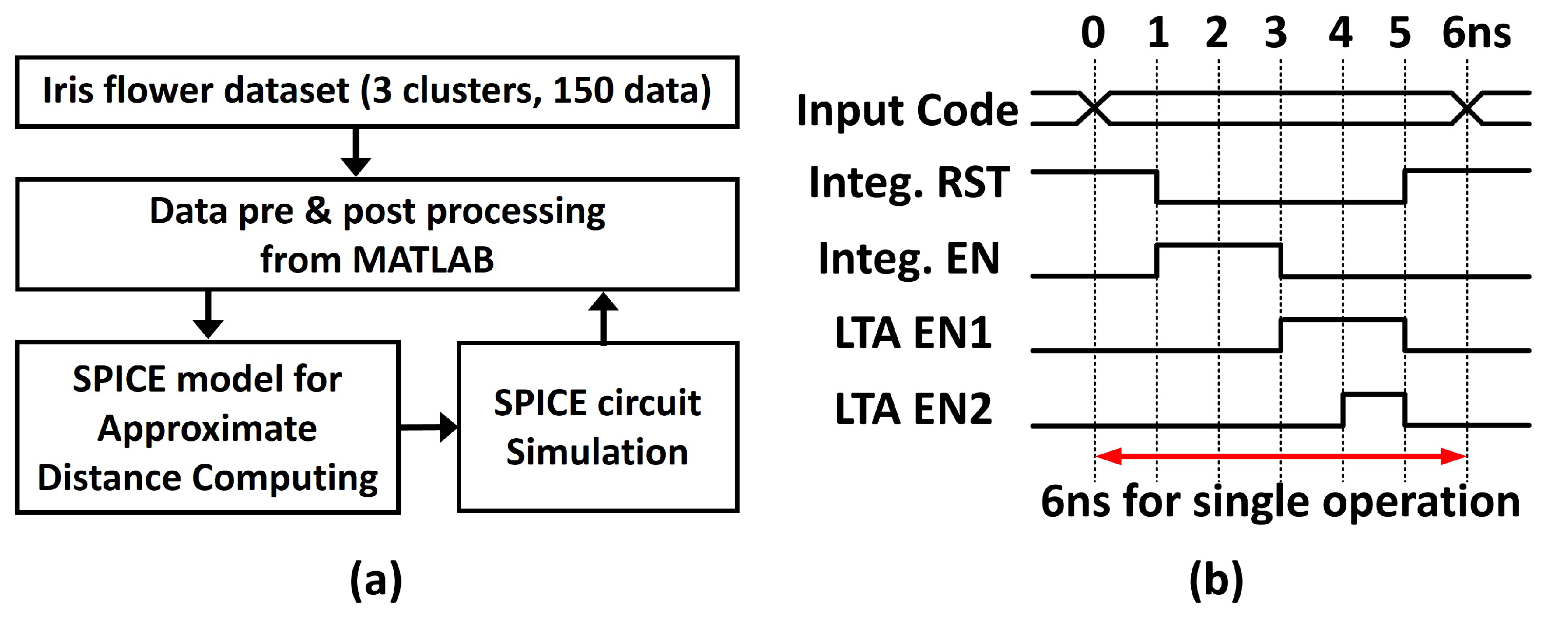
6.1. Simulation Framework and Timing Diagram

For clustering accuracy and energy analysis, we will first introduce a circuit-application co-simulation framework used in this work, which is depicted in Figure 10a. Based on our proposed K-means clustering module, SPICE simulations were performed on clustering with the necessary pre- and post-processing performed in MATLAB. Here, the preprocessing reads data from the Iris dataset and quantizes the vector components of the individual data to 5-bit resolution. Then, SPICE simulation is performed based on the input file generated by MATLAB containing quantized input data. When the SPICE simulation is completed, the address of the loser is collected and stored in the workspace of MATLAB. By repeating this process, we can calculate the distance of each datum and perform clustering work.
All the CMOS circuits were designed using IBM 45 nm SOI technology with 1 V power supply. The associated timing diagram is shown in Figure 10b. The ‘Integ. RST’, ‘Integ. EN’, ‘LTA EN1’ and ‘LTA EN2’ represent the reset and enable signal of the integrator; and the first and second layer enable signals of the LTA circuit, respectively. As indicated by the the timing diagram, a single clustering operation can be performed in 6 ns, which is much faster than other distance computing units (based on current mode calculation) in the literature [18,19].

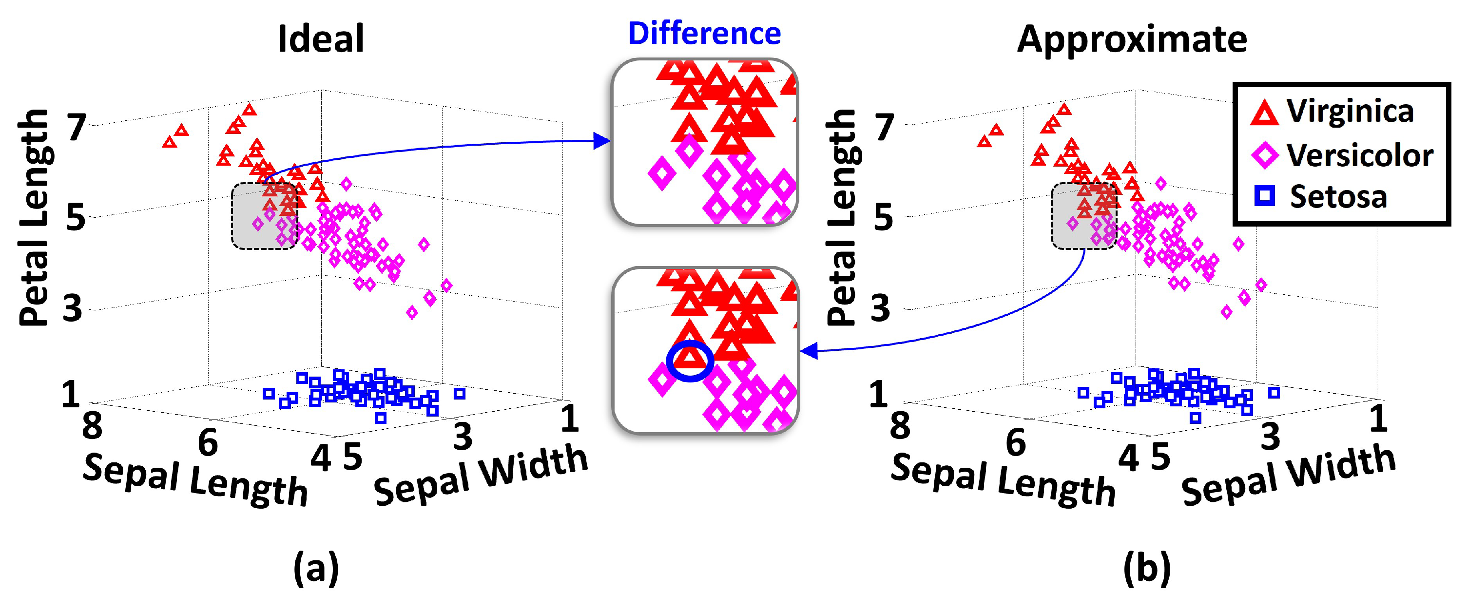
6.2. Clustering Result

Figure 11 depicts the final clustering results for both the ideal case (from MATLAB built-in function ‘kmeans’) and the proposed design based on the circuit-application co-simulation framework. The design performs reasonably well, and the only misclassification error occurs at the boundary between the two clusters, which is quite understandable.

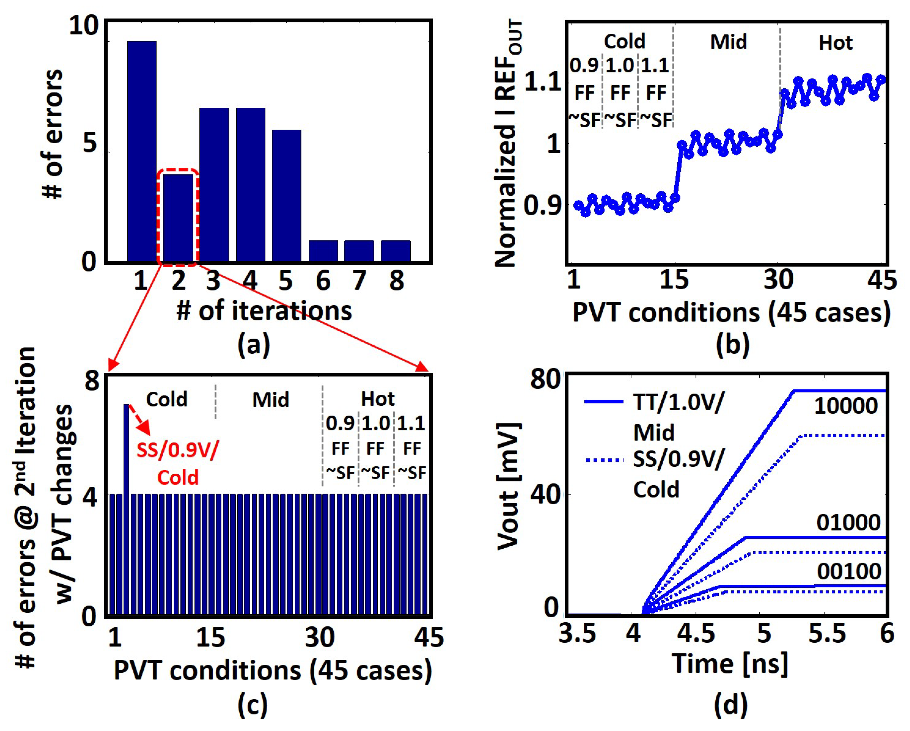
6.3. Clustering under Different PVT Conditions

Figure 12a depicts the average number of errors (averaged over eight runs) during the clustering process. The error reduces to 1 out of 150 data-points at the end of six iterations. To check the robustness of the proposed system under PVT changes, we also performed the clustering operation under different PVT conditions. For each PVT condition, we used five processes (TT/FF/SS/FS/SF), three voltages (0.9 V/1.0 V/1.1 V), and three temperatures (0 C/50 C/100 C), which results in a total of 45 different combinations. Based on these settings, Figure 12b shows the output current variation from a current reference circuit. The current reference circuit was designed to exhibit the property of process and voltage robustness [29]. However, it is not temperature compensated, which results in ± 10 % variation, mainly due to temperature changes. This variation affects the output voltage level of the distance computing units. However, this does not necessarily imply additional errors in the clustering process due to the inherent error resiliency of such applications. Figure 12c shows the clustering error during the second iteration in Figure 12a under the 45 PVT conditions. The number of errors at the second iteration was originally four at the typical condition. As can be seen from the results, the number of errors only increased for a single corner SS/0.9 V/Low temperature. At this condition, additional clustering errors occur at the comparator in the last LTA stage due to the low-voltage headroom and high-threshold voltage of transistors due to the harsh PVT conditions. This problem can be resolved by improving the final comparator stage. Note that the number of clustering errors under PVT changes is almost similar in comparison to the typical case. Figure 12d depicts two groups of waveforms from different corners; one is the typical condition, and the other is slow process and low VDD condition. As expected, the voltage level under worse PVT conditions reduces (for the same digital code) due to reduced current. However, it is worth noting here that the voltage level variation at a specific corner affects all distance computing units concurrently at the same time. Hence, the sorting operation of the voltage levels is not affected, even under PVT changes, which ensures that final clustering results are not affected.

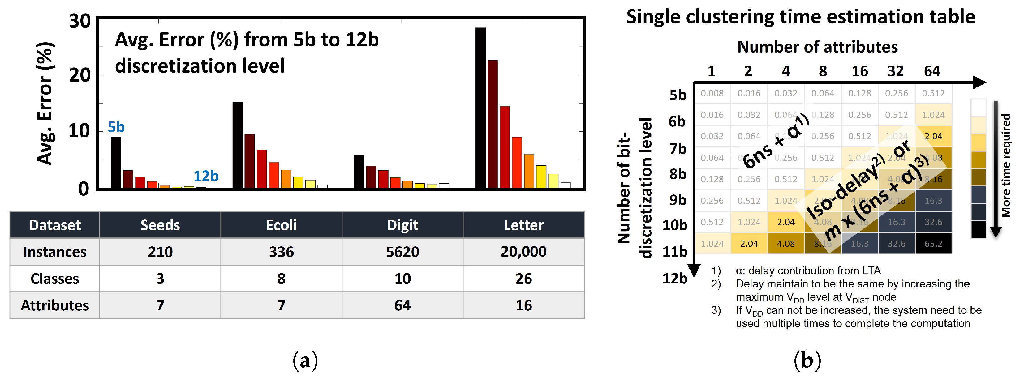
6.4. Clustering Results with Other Datasets

To validate the scalability of the system, we checked the performance of the proposed approximate K-means clustering hardware based on different datasets. The following four datasets [23] were used: (1) Seeds dataset (210 instances, 3 classes, and 7 attributes), (2) Ecoli dataset (336 instances, 8 classes, and 7 attributes), (3) Optical recognition of Handwritten Digits dataset (5620 instances, 10 classes, and 64 attributes), and lastly, (4) Letter recognition dataset (20,000 instances, 26 classes, and 16 attributes).
The accuracy of the hardware proposed here was measured in the following two steps. First, the initial centroids of the dataset under consideration were randomly selected, and then the clustering output of a given dataset, that is, a reference index, was created using the software ‘kmeans’ function. Thereafter, the clustering function is performed using the proposed hardware k-means clustering system with the same initial centroids, and whether the output index of our system matches the reference index is checked. To obtain an average error, 1000 clustering operations are performed per dataset by different conditions.
Figure 13a shows the resulting graph in which the average error (in percentage) generated by the proposed system depends on the number of bit discretization levels. The 5-bit resolution of the input data was sufficient for a simple Iris dataset, but the inclusion of more attributes and classes in the dataset increases the bit resolution required for accurate calculations.
It is worth noting here that the required accuracy level depends on the target application. If the target system allows only 1% of total clustering errors, 8-bit resolution is required for the Seeds dataset and 11-bit resolution seems to be fine for the Ecoli dataset. One of the important properties found in the accuracy graph is that the number of bit resolutions required does not strongly depend on the number of instances, classes and attributes of the dataset. Rather than these attributes, it is important how small incremental numbers should be mapped to 1 LSB when converting the floating-point number of input data into binary data. However, it does not necessarily mean that high-resolution systems always consume more power. This is because, if the amount and period of the current pulses of the proposed distance computation core are properly adjusted, an input with high bit resolution could be processed with little or only a slight increase in current consumed by the system.
Lastly, we will explain that the estimated execution time of the proposed approximate clustering hardware depends on (1) the number of instances in the dataset and (2) the number of attributes per instance. The proposed system executes a single clustering operation for each input instance based on the timing diagram in Figure 10b. This implies that the total clustering time varies linearly depending on the number of instances of each dataset. However, the execution time of a single clustering operation becomes a function of (1) the number of attributes of each input instance and (2) the number of bit-discretization levels. The graph in Figure 13b shows that the estimated single clustering time varies according to the two factors mentioned above. Note that areas with the same color have equal clustering times.
As shown in the figure, if the input data have a combination of two factors within region A (white area), the system completes the clustering operation within (4 ns + α ) time, where α represents the delay contribution from the LTA unit. Here, the LTA delay is determined by the number of clusters (‘k’) of the dataset, and the delay can be calculated as 1 ns × log 2 ( k ) . For example, if there are four clusters (k = 4) in a particular dataset, the delay contribution of the LTA becomes 2 ns, which leads to 6 ns of total clustering time, as shown in Figure 10b.
However, if a combination of the number of attributes and the bit-discretization level falls within region B, the system may or may not need additional time to complete clustering. The reason behind this interesting property lies in the unique characteristic of the proposed system, in which the multiplication output of the proposed distance calculation core is expressed as a voltage level. This means that if a given process technology allows a higher VDD level (e.g., analog VDD, typically 2–3 times higher than a nominal VDD voltage), our system can internally accommodate more distance computation units (or more approximate multipliers) that the output is represented and added in terms of the voltage level. This allows a given system to calculate the distance without additional computation time. On the other hand, if no additional voltage headroom is allowed in a particular process technology, the input vector should be divided into different ‘n’ groups and distance calculations need to be repeated using the proposed system for each group. This makes the total computation time of n× (4 ns) + α , which is proportional to the change in the two variables.

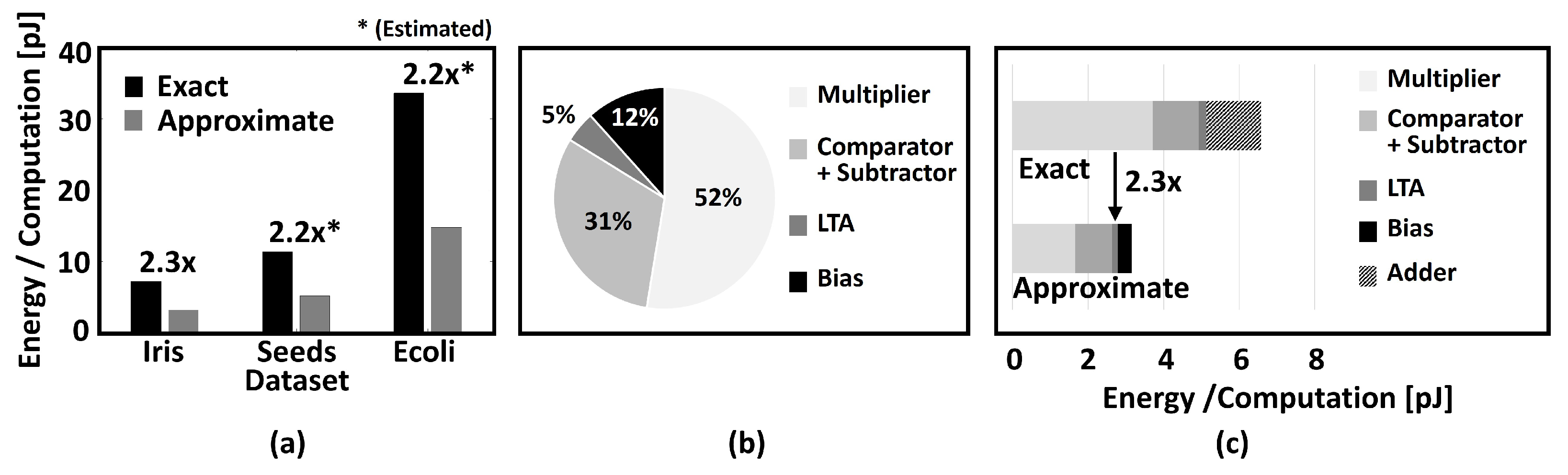
6.5. Energy Analysis

Let us now consider the average energy consumption involved in K-means clustering. For the particular Iris dataset being considered in this work, three clusters and four dimensions per vector result in twelve multipliers, digital comparators and subtractors for the corresponding hardware implementation. Additionally, a bias circuit and LTA units are required. The average energy consumption of the entire circuit during a single K-means clustering operation (duration: 6 ns) was estimated to be ∼3.15 pJ. As described earlier in this section, a baseline digital CMOS implementation (with the same input bit discretization) was synthesized using the same process technology. Compared to the synthesized digital CMOS baseline, our approach can potentially achieve ∼2.3× lower energy consumption. We also estimated the energy benefit of the proposed design using different datasets, such as Seeds [23] (three clusters, seven dimensions) and Ecoli [23] (eight clusters, eight dimensions). Figure 14a summarizes the total energy consumption and improvement for each dataset. The energy consumed by each component of the proposed design and the CMOS baseline are depicted in Figure 14b,c, respectively. Although the multiplier energy consumption is still the dominant component, it is almost reduced by half in comparison to the CMOS baseline.
Additionally, Table 1 provides a comparison of the proposed approach with previous work based on analog [18,19], mixed-signal [17] and digital [21,22] implementations for similar applications based on the same distance metric. Even though the target application of [18,21,22] and [17] are nearest neighbor search and associative memory, respectively, the baseline operation is quite similar. Since the power, search time, and energy consumption of the system is dependent on the data size, the corresponding numbers of our proposed scheme were evaluated for each set of data dimensions in the analog and digital implementations (mentioned in braces for the power, time, and energy entries in Table 1. It is worth noting here that although our approach consumes more power than some competitors, the search time is significantly shortened, resulting in lower resultant energy consumption.

7. Conclusions

This work describes a novel mixed-signal approach to distance computation between two input vectors. The design principle is based on the simple concept of charge stored on a capacitor due to an input current. While conventional digital designs tend to be fast and power hungry, analog designs are slower and prone to PVT changes. The approximate K-means clustering circuit was designed using IBM 45 nm SOI technology and verified through SPICE simulations. MATLAB was used for pre- and post-processing of data. The proposed approximate mixed-signal computing unit offers the advantage of resiliency to PVT changes and performs distance computation with high throughput and low energy, thereby resulting in an energy-efficient design that can potentially be utilized for low-power signal processing tasks. Finally, we envision that the limited scope of application based on the proposed approximate K-means clustering system could be resolved through future works targeting interdisciplinary studies on neural networks and K-means clustering, as shown in recent research [30,31].

Author Contributions

Conceptualization, methodology, and validation, Y.S.; investigation resources and data curation, S.-W.C., M.-G.Y. and K.-Y.C.; writing—original draft preparation, Y.S.; writing—review and editing, K.-H.B. and Y.S.; supervision and project administration, Y.S. All authors have read and agreed to the published version of the manuscript.

Funding

This work was supported in part by the National Research Foundation of Korea(NRF) grant funded by the Korea government(MSIT) under Grant 2021R1C1C1008752, in part by the Chung-Ang University Graduate Research Scholarship in 2020, and in part by the Technology Innovation Program (or the Industrial Strategic Technology Development Program) and Royalty Free Processor and Software Platform Development for Low Power IoT and Wearable Device Devices funded by the Ministry of Trade, Industry and Energy (MOTIE, South Korea) under Grant 10077381.

Conflicts of Interest

The authors declare no conflict of interest.

References

  1. Sinaga, K.P.; Yang, M.S. Unsupervised K-Means Clustering Algorithm. IEEE Access 2020, 8, 80716–80727. [Google Scholar] [CrossRef]
  2. Ding, C.; He, X. K-Means Clustering via Principal Component Analysis. In Proceedings of the Twenty-First International Conference on Machine Learning, Banff, AB, Canada, 4–8 July 2004; p. 29. [Google Scholar] [CrossRef]
  3. Jain, A.K. Data clustering: 50 years beyond K-means. Pattern Recognit. Lett. 2010, 31, 651–666. [Google Scholar] [CrossRef]
  4. Mat Isa, N.A.; Salamah, S.A.; Ngah, U.K. Adaptive fuzzy moving K-means clustering algorithm for image segmentation. IEEE Trans. Consum. Electron. 2009, 55, 2145–2153. [Google Scholar] [CrossRef]
  5. Chen, T.W.; Chien, S.Y. Bandwidth Adaptive Hardware Architecture of K-Means Clustering for Video Analysis. IEEE Trans. Very Large Scale Integr. (VLSI) Syst. 2010, 18, 957–966. [Google Scholar] [CrossRef]
  6. He, Z.; Yu, C. Clustering Stability-Based Evolutionary K-Means. Soft Comput. 2019, 23, 305–321. [Google Scholar] [CrossRef]
  7. Sharma, K.K.; Seal, A. Clustering analysis using an adaptive fused distance. Eng. Appl. Artif. Intell. 2020, 96, 103928. [Google Scholar] [CrossRef]
  8. Karlekar, A.; Seal, A.; Krejcar, O.; Gonzalo-Martin, C. Fuzzy K-Means Using Non-Linear S-Distance. IEEE Access 2019, 7, 55121–55131. [Google Scholar] [CrossRef]
  9. Seal, A.; Karlekar, A.; Krejcar, O.; Gonzalo-Martin, C. Fuzzy c-means clustering using Jeffreys-divergence based similarity measure. Appl. Soft Comput. 2020, 88, 106016. [Google Scholar] [CrossRef]
  10. Seal, A.; Herrera Viedma, E. Performance and Convergence Analysis of Modified C-Means Using Jeffreys-Divergence for Clustering. Int. J. Interact. Multimed. Artif. Intell. 2021, 7, 141–149. [Google Scholar] [CrossRef]
  11. Liu, B.D.; Chen, C.Y.; Tsao, J.Y. A modular current-mode classifier circuit for template matching application. Circuits Syst. II Analog. Digit. Signal Process. IEEE Trans. 2000, 47, 145–151. [Google Scholar]
  12. Vlassis, S.; Fikos, G.; Siskos, S. A floating gate CMOS Euclidean distance calculator and its application to hand-written digit recognition. In Proceedings of the 2001 International Conference on Image Processing (Cat. No.01CH37205), Thessaloniki, Greece, 7–10 October 2001; Volume 3, pp. 350–353. [Google Scholar]
  13. Gopalan, A.; Titus, A.H. A new wide range Euclidean distance circuit for neural network hardware implementations. Neural Netw. IEEE Trans. 2003, 14, 1176–1186. [Google Scholar] [CrossRef] [PubMed]
  14. Bult, K.; Wallinga, H. A class of analog CMOS circuits based on the square-law characteristic of an MOS transistor in saturation. IEEE J. -Solid-State Circuits 1987, 22, 357–365. [Google Scholar] [CrossRef] [Green Version]
  15. Cauwenberghs, G.; Pedroni, V. A low-power CMOS analog vector quantizer. IEEE J. -Solid-State Circuits 1997, 32, 1278–1283. [Google Scholar] [CrossRef] [Green Version]
  16. Liu, S.I.; Chang, C.C. A CMOS square-law vector summation circuit. IEEE Trans. Circuits Syst. II Analog. Digit. Signal Process. 1996, 43, 520–523. [Google Scholar] [CrossRef]
  17. Harada, Y.; Fujimoto, K.; Fukuhara, M.; Yoshida, M. A Minimum Hamming Distance Search Associative Memory Using Neuron CMOS Inverters. Electron. Commun. Jpn. 2017, 100, 10–18. [Google Scholar] [CrossRef]
  18. Talaśka, T.; Kolasa, M.; Długosz, R.; Pedrycz, W. Analog Programmable Distance Calculation Circuit for Winner Takes All Neural Network Realized in the CMOS Technology. IEEE Trans. Neural Netw. Learn. Syst. 2016, 27, 661–673. [Google Scholar] [CrossRef] [PubMed]
  19. Lu, J.; Young, S.; Arel, I.; Holleman, J. An analog online clustering circuit in 130 nm CMOS. In Proceedings of the Solid-State Circuits Conference (A-SSCC), 2013 IEEE Asian, Singapore, 11–13 November 2013; pp. 177–180. [Google Scholar]
  20. Abedin, M.A.; Tanaka, Y.; Ahmadi, A.; Koide, T.; Mattausch, H.J. Mixed Digital–Analog Associative Memory Enabling Fully-Parallel Nearest Euclidean Distance Search. Jpn. J. Appl. Phys. 2007, 46, 2231. [Google Scholar] [CrossRef]
  21. An, F.; Akazawa, T.; Yamazaki, S.; Chen, L.; Mattausch, H.J. A coprocessor for clock-mapping-based nearest Euclidean distance search with feature vector dimension adaptability. In Proceedings of the IEEE 2014 Custom Integrated Circuits Conference, CICC 2014, San Jose, CA, USA, 15–17 September 2014; pp. 1–4. [Google Scholar]
  22. An, F.; Mihara, K.; Yamasaki, S.; Chen, L.; Jurgen, M. K-Nearest Neighbor Associative Memory with Reconfigurable Word-Parallel Architecture. JSTS J. Semicond. Technol. Sci. 2016, 16, 405–414. [Google Scholar] [CrossRef] [Green Version]
  23. Available online: https://archive.ics.uci.edu/ml/datasets/ (accessed on 30 November 2021).
  24. Demosthenous, A.; Smedley, S.; Taylor, J. A CMOS analog winner-take-all network for large-scale applications. Circuits Syst. I Fundam. Theory Appl. IEEE Trans. 1998, 45, 300–304. [Google Scholar] [CrossRef]
  25. Aksin, D.Y. A high-precision high-resolution WTA-MAX circuit of O (N) complexity. Circuits Syst. II Analog. Digit. Signal Process. IEEE Trans. 2002, 49, 48–53. [Google Scholar] [CrossRef]
  26. Ito, K.; Ogawa, M.; Shibata, T. A high-performance ramp-voltage-scan winner-take-all circuit in an open loop architecture. Jpn. J. Appl. Phys. 2002, 41, 2301. [Google Scholar] [CrossRef]
  27. Bottou, L.; Bengio, Y. Convergence Properties of the K-Means Algorithms. In Advances in Neural Information Processing Systems; Tesauro, G., Touretzky, D., Leen, T., Eds.; MIT Press: Cambridge, MA, USA, 1995; Volume 7. [Google Scholar]
  28. Selim, S.Z.; Ismail, M.A. K-Means-Type Algorithms: A Generalized Convergence Theorem and Characterization of Local Optimality. IEEE Trans. Pattern Anal. Mach. Intell. 1984, PAMI-6, 81–87. [Google Scholar] [CrossRef]
  29. Baker, R.J. CMOS: Circuit Design, Layout, and Simulation, 3rd ed.; Wiley: New York, NY, USA, 2010. [Google Scholar]
  30. He, B.; Qiao, F.; Chen, W.; Wen, Y. Fully convolution neural network combined with K-means clustering algorithm for image segmentation. In Proceedings of the Tenth International Conference on Digital Image Processing (ICDIP 2018), Shanghai, China, 11–14 May 2018; pp. 760–766. [Google Scholar] [CrossRef]
  31. Cho, M.; Alizadeh-Vahid, K.; Adya, S.; Rastegari, M. DKM: Differentiable K-Means Clustering Layer for Neural Network Compression. arXiv 2021, arXiv:2108.12659. [Google Scholar]
Figure 1. Multiplication based on charging a capacitor using an input current: (a) L 1 norm with fixed input current; (b) L 2 2 norm with variable input current.
Electronics 11 00298 g001
Figure 2. Hardware implementation of the approximate multiplier unit for distance computation. (a) Conceptual view (b) Actual implementation.
Electronics 11 00298 g002
Figure 3. Proposed approximate distance computing unit based on the circuit in Figure 2b.
Electronics 11 00298 g003
Figure 4. (a) Basic circuit of the timing controller, (b) the proposed Pulse Width Modulation circuit with RC discharging path, (c) timing diagram and expected waveforms for the controller, and (d) simulation results of 1-step delay increment with changes in the input code.
Electronics 11 00298 g004
Figure 5. Current, Voltage output plots, and corresponding output curve of the proposed design for two different input sets: (a) integration time is fixed, current is varying; (b) integration time and current are both varying together.
Electronics 11 00298 g005
Figure 6. (a) Flowchart of the K-means clustering algorithm; (b) distance table generated for each iteration of the clustering process.
Electronics 11 00298 g006
Figure 7. Architecture of the proposed “K-means clustering unit”.
Electronics 11 00298 g007
Figure 8. (a) Summation Unit for the proposed “Main Distance Computing Unit”; (b) Loser-Take-All (LTA) circuit based on cell-based tree structure and its inherent address decoding property (left), 2:1 multiplexer (right-top), and comparator (right-bottom) used for LTA unit.
Electronics 11 00298 g008
Figure 9. The layout of the proposed “K-means clustering unit”.
Electronics 11 00298 g009
Figure 10. (a) Circuit-application co-simulation framework used for this work; (b) timing diagram for the proposed K-means clustering module.
Electronics 11 00298 g010
Figure 11. Final clustering results comparison: (a) ideal K-means clustering result; (b) approximate K-means clustering result. The single error occurs at the boundary of the two clusters.
Electronics 11 00298 g011
Figure 12. (a) Average number of clustering errors during the K-means clustering process; (b) normalized current reference output with PVT changes; (c) the number of clustering errors during second iteration in (a) with PVT changes; (d) output voltage levels from a distance computing unit with three different inputs under two PVT conditions.
Electronics 11 00298 g012
Figure 13. (a) Clustering accuracy for different datasets; (b) clustering execution time of the proposed approximate K-means clustering hardware.
Electronics 11 00298 g013
Figure 14. (a) Comparison of the energy consumption of the proposed distance computing unit with respect to digital CMOS technology; (b) energy consumption of each component of the proposed design; (c) component-wise energy comparison with digital CMOS implementation.
Electronics 11 00298 g014
Table 1. Performance comparison.
AnalogAnalogMixedDigitalDigitalThis Work
[19][18][17][21][22](Mixed)
ApplicationClusteringNearest NeighborAssociative MemoryNearest NeighborNearest NeighborClustering
Dist. Metric L 1 / L 2 2 L 1 / L 2 2 L 1 L 2 2 L 2 2 L 1 / L 2 2
Technology130 nm180 nm180 nm180 nm180 nm45 nm
Data size (Centroids/
Dimensions)
4 / 8 3 / 4 8 bits 32 words 32 / 8 32 / 8 3 / 4
VDD3 V1.8 V1.8 V1.8 V1.8 V1.0 V
Power (Estimated)15 uW
( 1.26 )  mW
0.22 mW
( 0.52 )  mW
<5.53 mW 5.02 mW
( 9.57 )  mW
13.5 mW
( 9.57 )  mW
0.52 mW
Search Time (Estimated)250 us (6 ns)143 ns (6 ns)<7.29 ns<23 ns (9 ns) 3.99 us (9 ns)6 ns
Energy (Estimated)3.75 nJ (7.6 pJ)31.46 pJ
(3.15 pJ)
<72.5 pJ<115.4 pJ
(86.1 pJ)
53.9 nJ (86.1 pJ)3.15 pJ
Publisher’s Note: MDPI stays neutral with regard to jurisdictional claims in published maps and institutional affiliations.

