Article

Rapid and Easy Assessment of Friction and Load-Bearing Capacity in Thin Coatings

Centre for Mechanical Engineering, Materials and Processes (CEMMPRE), Department of Mechanical Engineering, University of Coimbra, 3030-788 Coimbra, Portugal
*
Author to whom correspondence should be addressed.
Electronics 2022, 11(3), 296; https://doi.org/10.3390/electronics11030296
Submission received: 7 December 2021 / Revised: 12 January 2022 / Accepted: 16 January 2022 / Published: 18 January 2022

Abstract

:
The present research paper aims to evaluate the tribological behavior of coatings in applications where high wear resistance and low friction are required, commonly used in refurbishment of various items of industrial equipment. Twelve tribological pairs made of six different coatings, corresponding to three different coating families, have been studied: TiSiN, Cr, and DLC (diamond-like carbon). The coatings were produced using a technique called high power impulse magnetron sputtering (HiPIMS). To perform the tribological tests, two methods were used to measure friction, namely energy dissipation in vibratory systems and sliding indentation. The first technique is based on the evaluation of free vibration movement with damping of a mass–spring system induced by a mechanical impulse where the contact between the vibrating device and the sample to be analyzed acts as an additional energy dissipation. At the same time, friction is determined through the inverse analysis by comparing the experimental vibratory movement with the analytical equation of the movement. The determination of the load-bearing capacity of the various coatings has been evaluated using sliding indentation tests against spherical bodies using a constant sliding speed and increasing normal loads. The results obtained in both tests allow to verify a relationship between the friction coefficients of the studied tribological pairs: µDLC < µTiSiN < µCr. This relationship does not occur in the case of the vibration test with the 100Cr6 counter-body.

1. Introduction

Friction and wear are two of the three phenomena studied by tribology and are identified as one of the main consumers of material and energy resources, which can be significantly optimized through various surface engineering techniques, such as the use of heat treatments, thermochemical surface treatments, and application of coatings, among others. The application of coatings is one of the most technically advanced solutions to maximize wear resistance [1]. Furthermore, wear and fatigue are the main root causes of industrial equipment breakdowns, causing very significant economic losses. Additionally, friction between moving components represents a very significant part of the energy consumed in industrial processes. Friction losses represent up to 25% of the energy consumed in paper pulp production processes [2] and 40% in mining equipment [3], corresponding on about 20% of the energy consumed by the industry [4]. Using the advantages resulting from the use of new materials and surface engineering, particularly concerning coatings, it will be possible to obtain significant reductions in friction and wear losses, which will also result in substantial energy gains and reduced CO2 emissions [4].
For these reasons, the use of coatings in the reconditioning of components during maintenance operations, will not only rise the service life, but also the reduction of energy losses by friction. There are several deposition processes to produce coatings, one of the most common being the physical vapor deposition process PVD (physical vapour deposition) [1,5,6,7]. High power impulse magnetron sputtering (HiPIMS) used in the production of thin coatings is based on magnetron sputtering with a pulsating energy source [8,9,10,11] where the energy used for ionization in the sputtering process is limited by the melting point of the target, even using refrigeration systems with high efficiency [11]. The HiPIMS technique thus allows solving the overheating problem by applying short duration energy pulses, but with a high power [12,13]. The use of DLC coatings has intensified as their deposition processes have improved [14]. Several studies on the tribological properties of DLC films reveal that, in all environments, their tribological behavior is controlled by an interfacial transfer layer formed during contact through friction-induced transformation between the contact material and the upper layer of DLC film, which acts as a solid self-lubricating agent [15,16]. Ti-Si-N nanocomposites have been the focus of study for over two decades, and they are mostly applied as coatings to protect components subject to high wear [17,18,19]. Cr is also widely used as an interlayer in multilayer coatings since it increases the adhesion between the films and the substrate where they are applied [20].
Friction is not a characteristic property of a particular material but rather an interaction between a pair of materials for certain contact conditions. Its estimate is influenced by a wide range of factors, leading to a discrepancy in the results obtained in different studies, especially when obtained by different methods, which makes understanding and comparing the tribological behavior of materials quite complex [21]. The study and in-depth knowledge of the tribological behavior of materials are imperative, not merely on an economic level but also due to a growing demand for a reduction in energy consumption. For example, it is estimated that of all the energy consumed in a conventional internal combustion engine, 33% are due to friction losses, with 20% of the total energy being dissipated exclusively in the contact between the piston rings and the cylinder [21]. However, the performance of the coating of mechanical components depends on the guarantee of a high load capacity [22]. Thus, there is a high need to apply knowledge in the domain of friction, wear, and lubrication in order to perform an adequate selection of materials for the most varied applications. However, the current routines, applied to characterize coated materials, concerning friction and load-bearing capacity, involve long duration and are very expensive. The main objective of the present research work is to deepen the knowledge of the tribological behavior and load-bearing capacity of coatings commonly used in various industrial sectors in applications where high wear resistance is required. The developed friction evaluation method is based on the evaluation of the vibration-free movement with damping of a spring–mass system induced by a mechanical impulse. The contact between the vibrating device and the sample to be analyzed acts as supplementary energy dissipation, and friction is determined through inverse analysis by comparing the experimental vibratory motion and the analytical equation of motion [23]. The load-bearing capacity of the various coatings under study was evaluated using sliding indentation tests with spherical bodies using for this a constant sliding speed and increasing normal loads. Wear and friction were thus evaluated in order to characterize the tribological behavior of the different coatings for certain contact conditions [24]. Therefore, the aim of this study is the demonstration of the ability of quick and easy characterization techniques, to apprize the performance of alternative coatings for mechanical components.

2. Materials and Methods

2.1. Materials

In the present research paper, twelve different tribological pairs were used. These tribological pairs are made up of six different coatings corresponding to three different coating families TiSiN, Cr, and DLC, deposited on AISI M2 tool steel, as shown in Table 1. During the tribological tests, two different methods were used to measure friction, energy dissipated in vibrating systems and sliding indentation. Two types of counterbodies were used in a sphere–plane configuration—spheres of steel 100Cr6 and Al2O3 ceramic balls.
The 100Cr6 bearing steel is low-alloyed martensitic steel, with high wear resistance, hardness in the order of 7 GPa, and modulus of elasticity in the order of 200 GPa. Al2O3 is a ceramic material also characterized by high wear resistance, hardness in the order of 15 GPa, and modulus of elasticity in the order of 380 GPa. Both spheres have a diameter of 10 mm and good surface quality, and it is not possible to observe any defect on the surface. The spherical shape of the counterbody is beneficial as it avoids misalignments during the performance of sliding tests and, at the same time, is responsible for high contact pressures, according to the Hertzian contact theory.

2.2. Tribological Testing

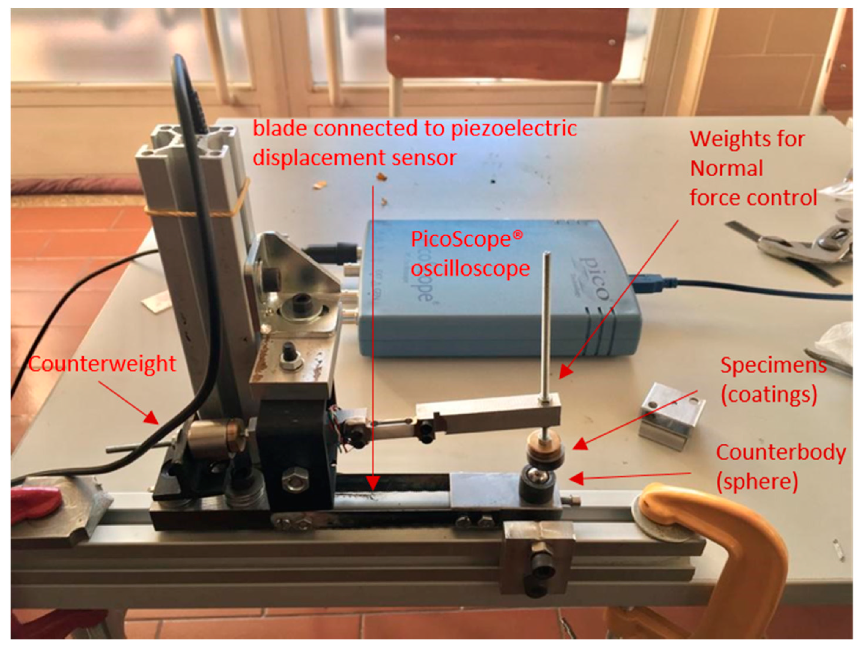
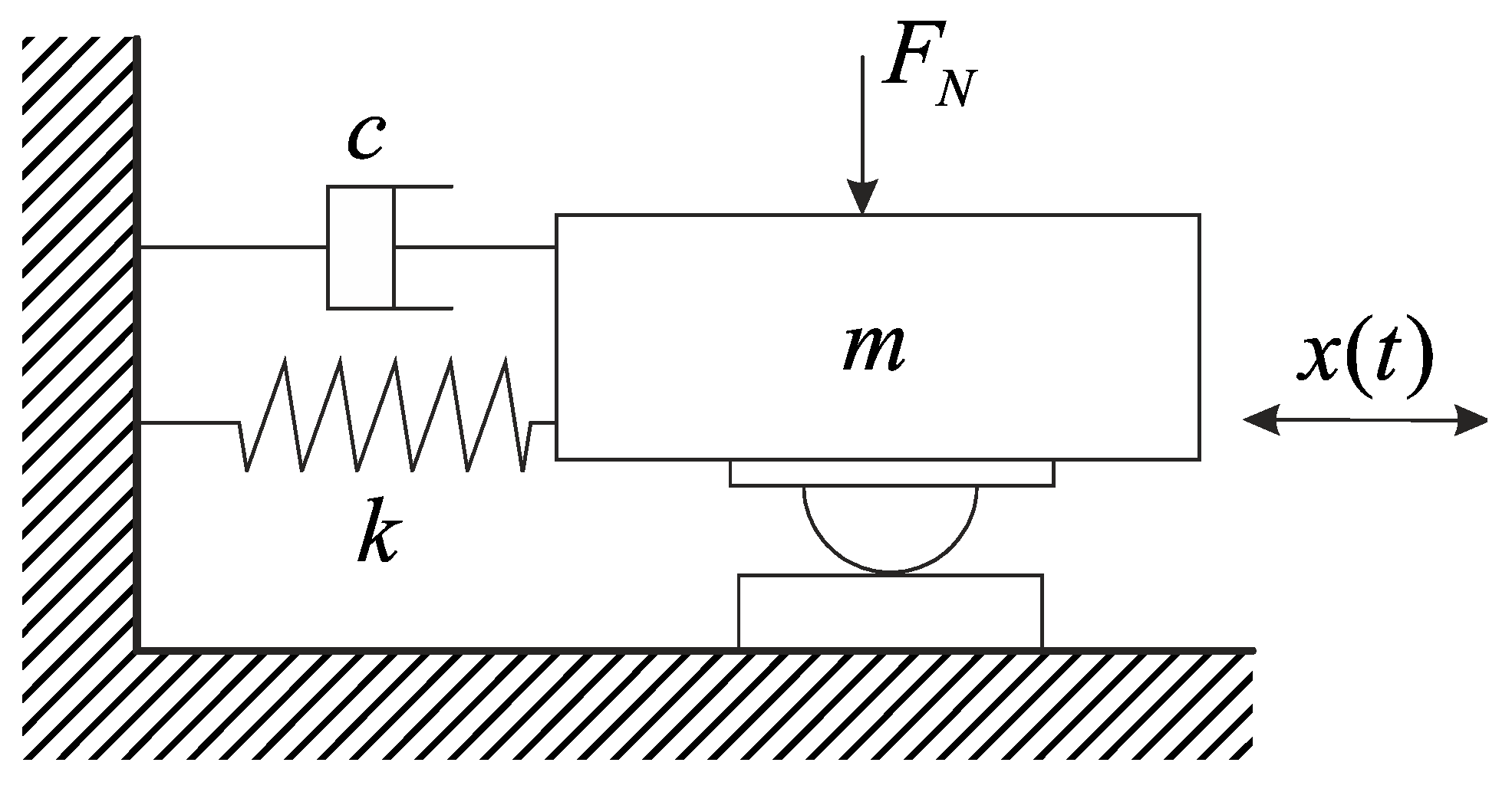
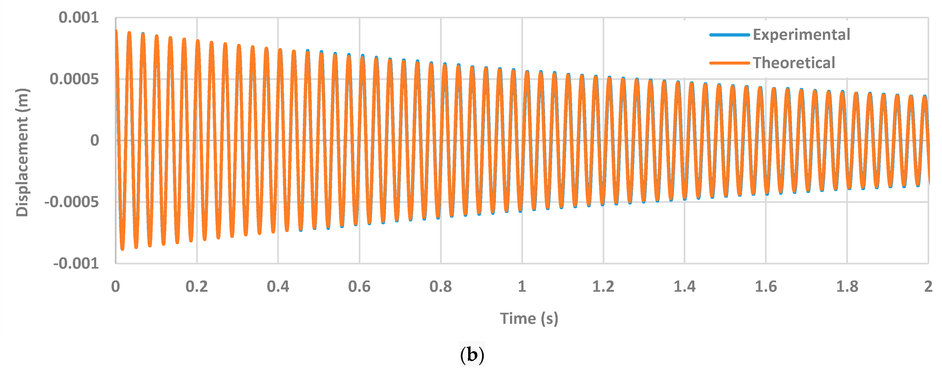
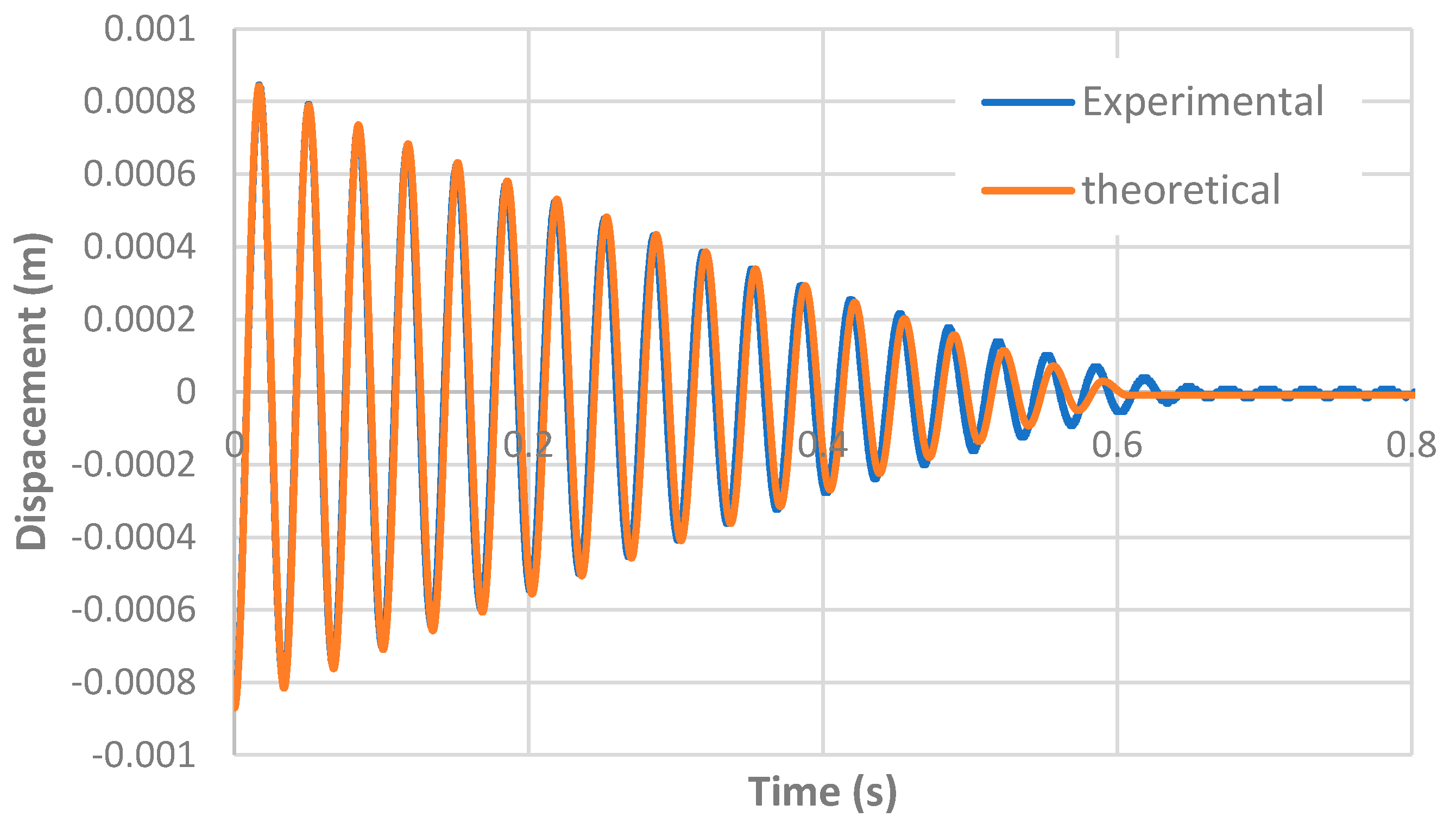
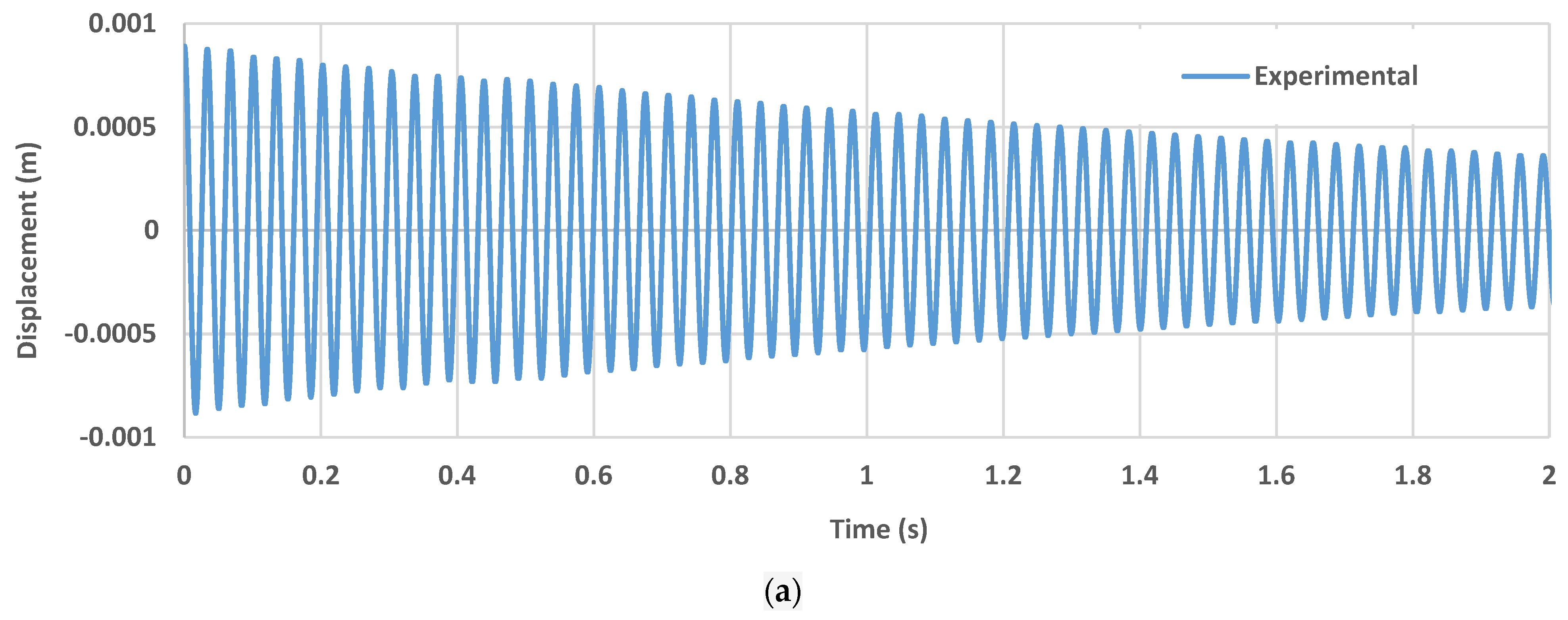
2.2.1. Measuring Friction through Energy Dissipated in Vibratory Systems

The energy dissipation by friction can be measured using vibratory systems. Rigaud et al. [25] developed a device called the “dynamic oscillating tribometer”. This tribometer consists of a pendulum with horizontal movement and aims to study the contribution of friction in lubricated systems based on the free-response of a damped oscillator with one degree of freedom [25].
The device is a spherical pin–plane contact tribometer with reciprocating movement where the horizontal oscillation of the pin is achieved through two flexible blades. The initial displacement of the pin is imposed through the electromagnet, verifying a horizontal deviation parallel to the sliding direction. When the pin is released, oscillations are produced in the system due to the release of elastic energy accumulated in the blades. The system’s dynamic response is measured using a laser vibrometer, allowing the analysis of its speed and vibrational displacement [25]. The methodology developed by Rigaud et al. [25] allowed the measurement of low friction coefficients with high precision and accuracy. The operation of this system consists of placing a tribological interface on an oscillator, providing it with initial mechanical energy, and letting it oscillate until it returns to its equilibrium position. Through the study of the frictional energy dissipation curve, during the free vibration of the oscillator, the contribution of the friction force in the movement can be analyzed as well as the type of dissipative mechanism involved in the contact [26].
To monitor the deformation of the blades and their entire vibratory movement, a piezoelectric sensor was used, which transforms the mechanical vibration into an electrical signal, connected to a PicoScope® 3206B PC USB digital oscilloscope for which the PicoScope 6 software was used. Figure 1 shows the different components from the dynamic oscillating tribometer used during experiments.
Figure 2 describes a mass–spring–damper vibratory system with concentrated parameters with a degree of freedom that can represent the vibratory movement of the equipment illustrated in Figure 1, being able to evaluate its dynamic response.
When there is no contact between the vibratory system and the sample, there is no energy dissipation by friction, and there is a damped free vibration movement that can be translated mathematically through Equation (1).
m x ¨ ( t ) + c x ˙   ( t ) + k x ( t ) = 0
where x(t) represents the position of the system in relation to the equilibrium position, k represents the stiffness constant of the spring, c is the damping constant, and m is the system’s mass. This equation has Equation (2) as a solution where X0 represents the initial position, ξ the damping factor, ωn the natural frequency of the system and ωa damped natural frequency.
x ( t ) = X o e ξ ω n t cos ( ω a t )    
If there is contact between the counterbody and the sample, then the friction is not negligible, and the motion equation contains one more dissipative term corresponding to the friction force, Equation (3). Where considering the Coulomb model, μ represents the friction coefficient, and FN is the normal contact force.
m x ¨ ( t ) + c x ˙   ( t ) + k x ( t ) = μ F N   | x ˙   ( t ) | x ˙   ( t )    
The analytical solution of Equation (3) represented in Equation (4) is quite complex and does not allow us to explicitly calculate the value of the friction coefficient.
x ( t ) = ( X i μ F N k   | x ˙   ( t ) | x ˙   ( t ) ) e ξ ω n ( t t i ) [ cos ( ω a ( t t i ) )                                 + ξ 1 ξ 2 sin ( ω a ( t t i ) ) ] + μ F N k   | x ˙   ( t ) | x ˙   ( t )
where t = ti = ti−1 + i(π/ωa) e Xi = x(ti) i = 1, 2, ..., n.
Thus, in order to obtain the friction coefficient, it was decided to carry out the integration numerically. In the scope of this work, the integration was performed, using the commercial Mathcad® program, with the implicit Adams–Bashforth numerical integration method and with an integration step equal to the signal acquisition rate. The friction coefficient is deduced through inverse analysis, that is, by comparing the experimental curve of free vibration with energy dissipation by friction and the curve obtained by integrating the theoretical motion equation. When a perfect overlap between the curves is reached, we can conclude that the friction coefficient that is being used in the calculation of the theoretical curve is identical to that measured experimentally. This condition is verified by least-squares optimization.
Figure 3 is shown the flowchart of the experimental protocol used to measure the coefficient of friction.

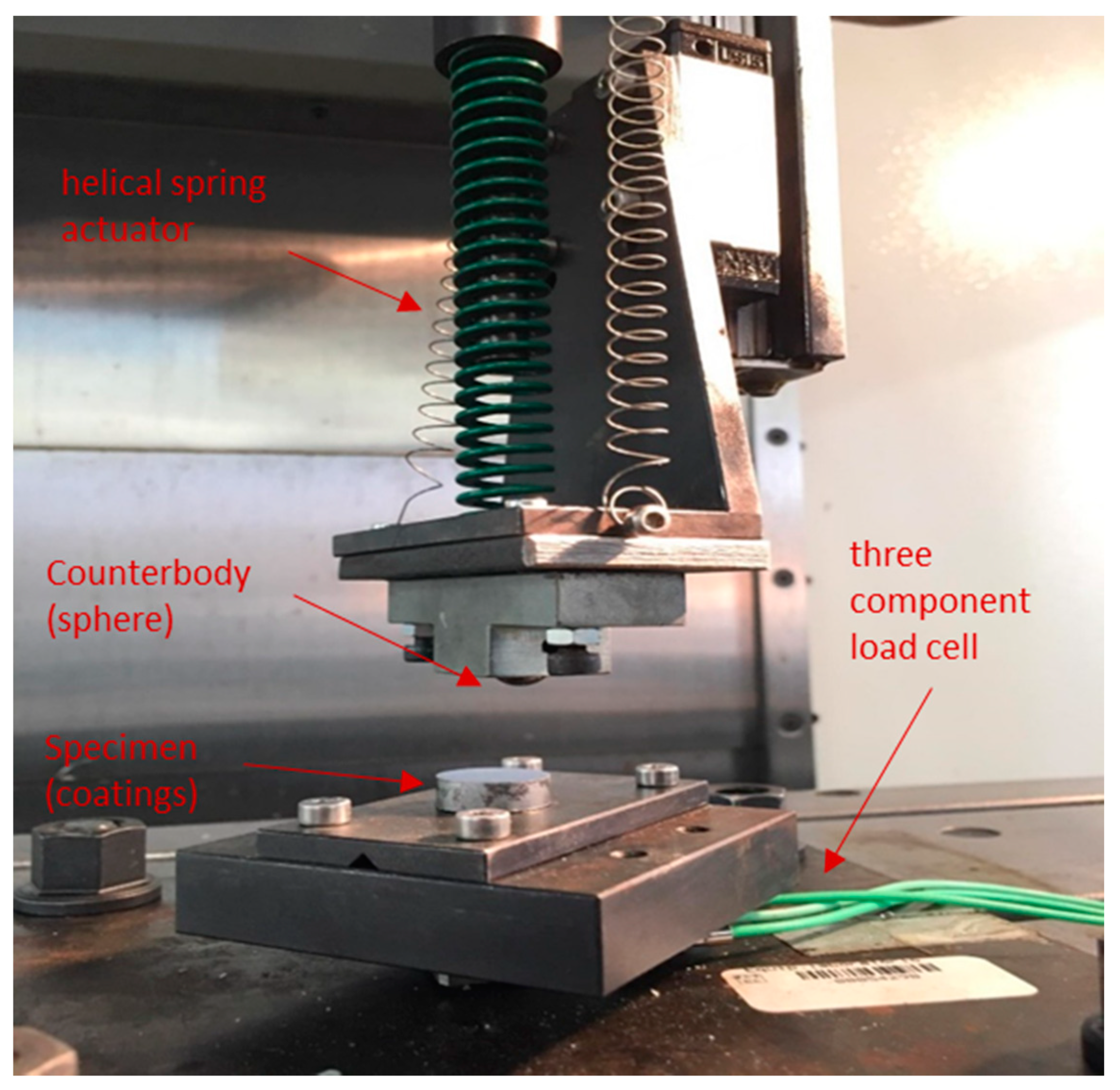
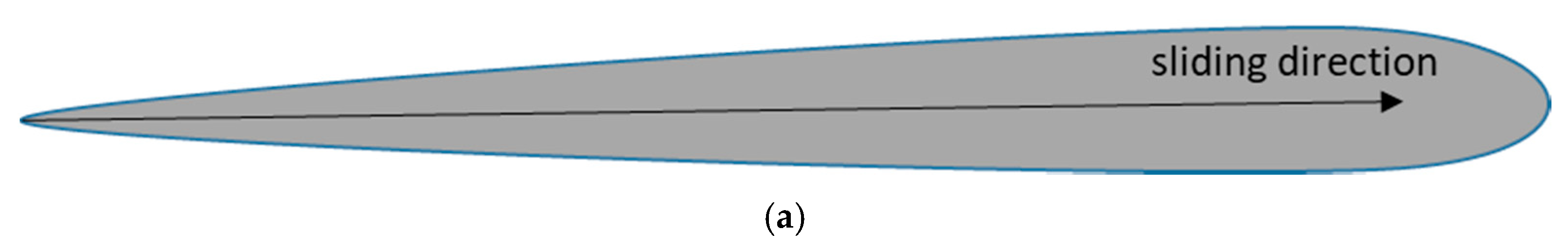
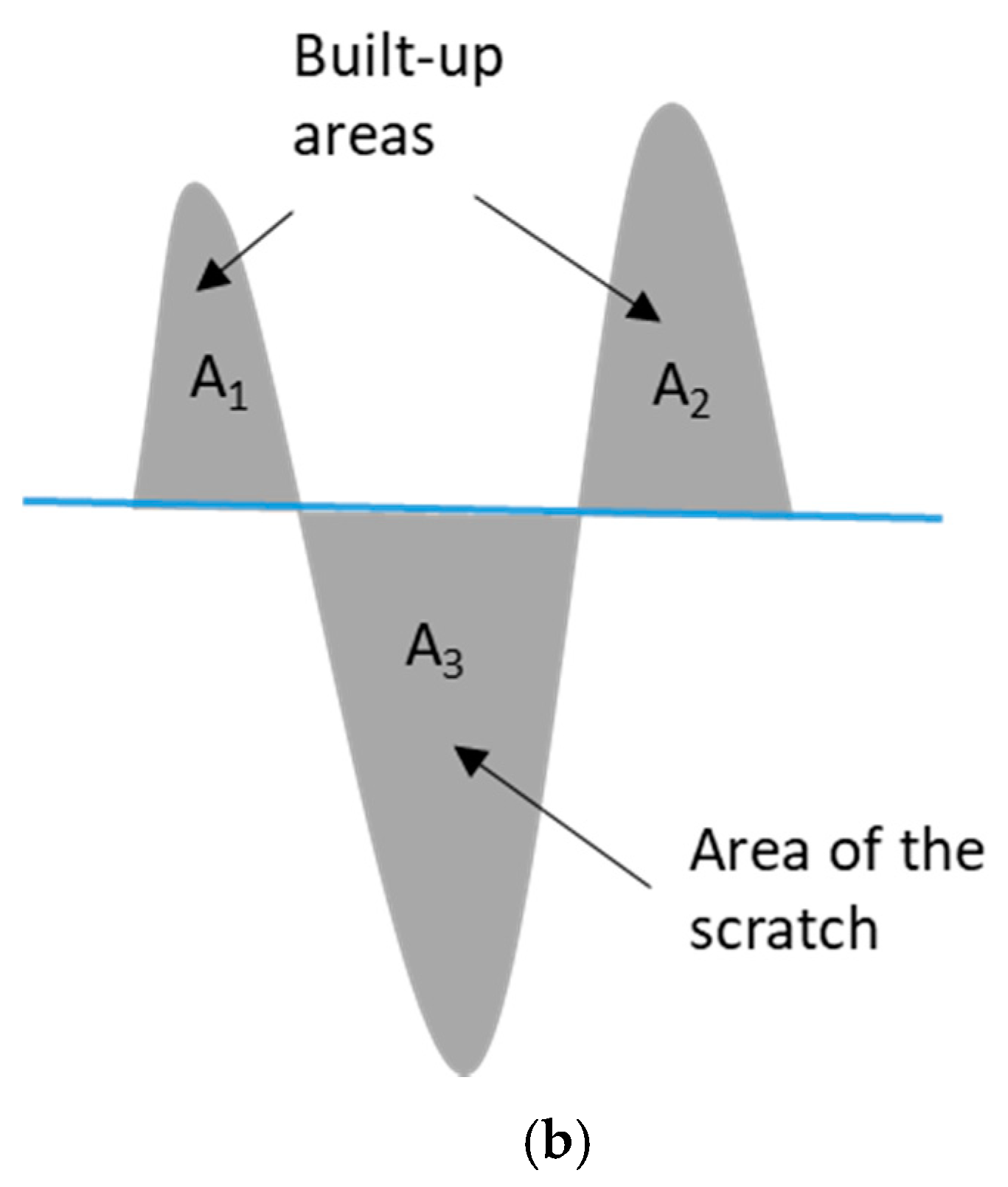
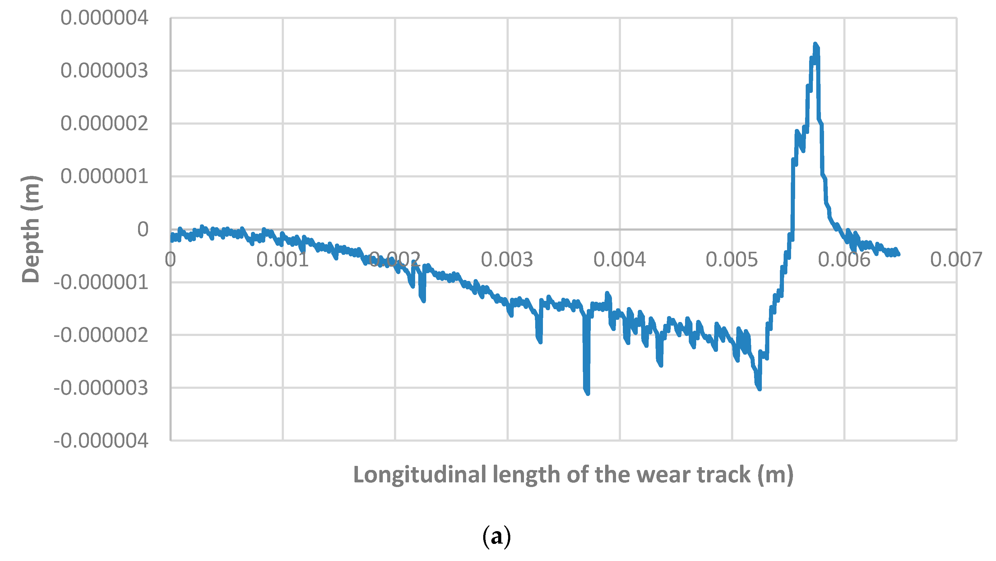
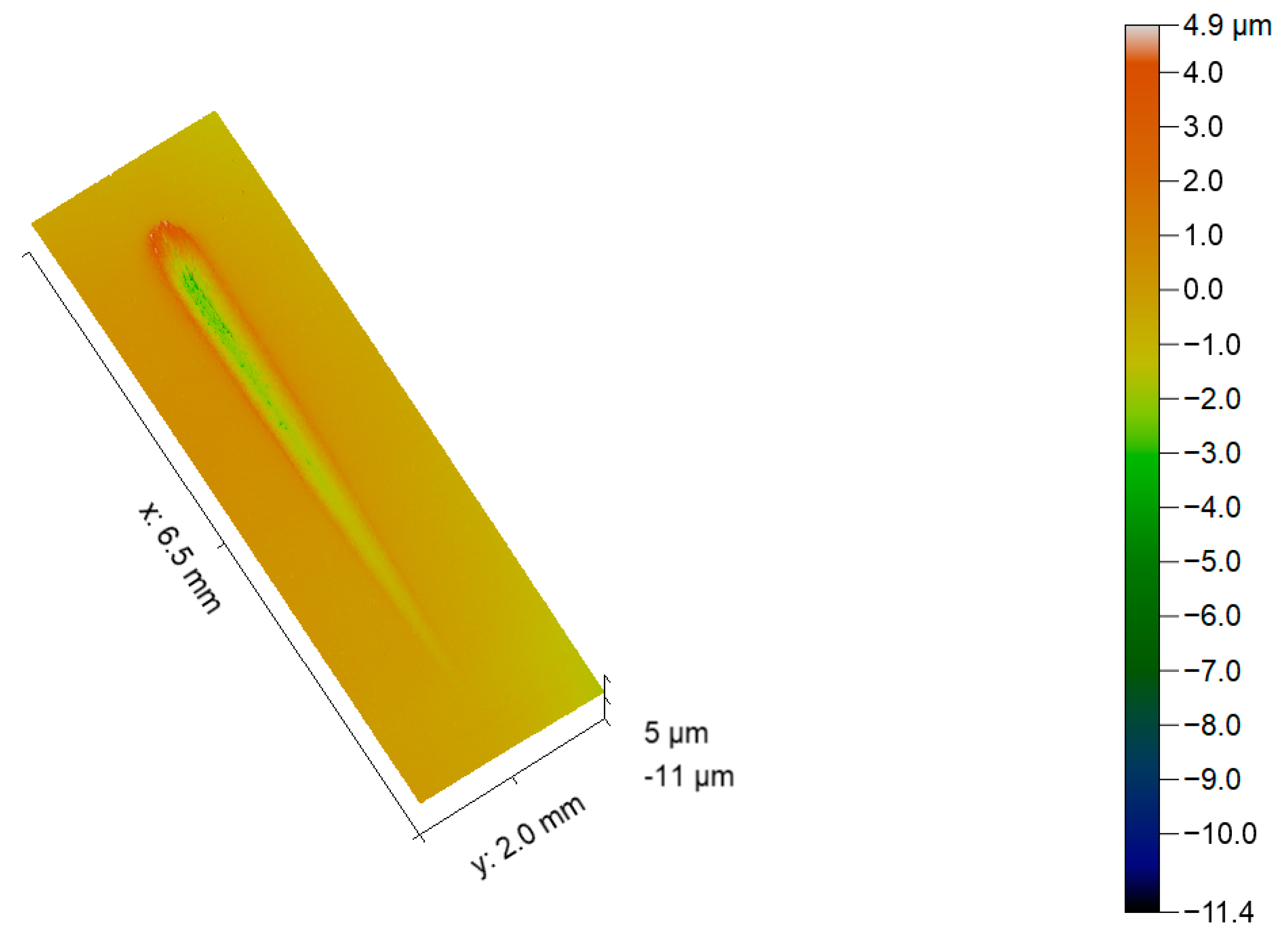
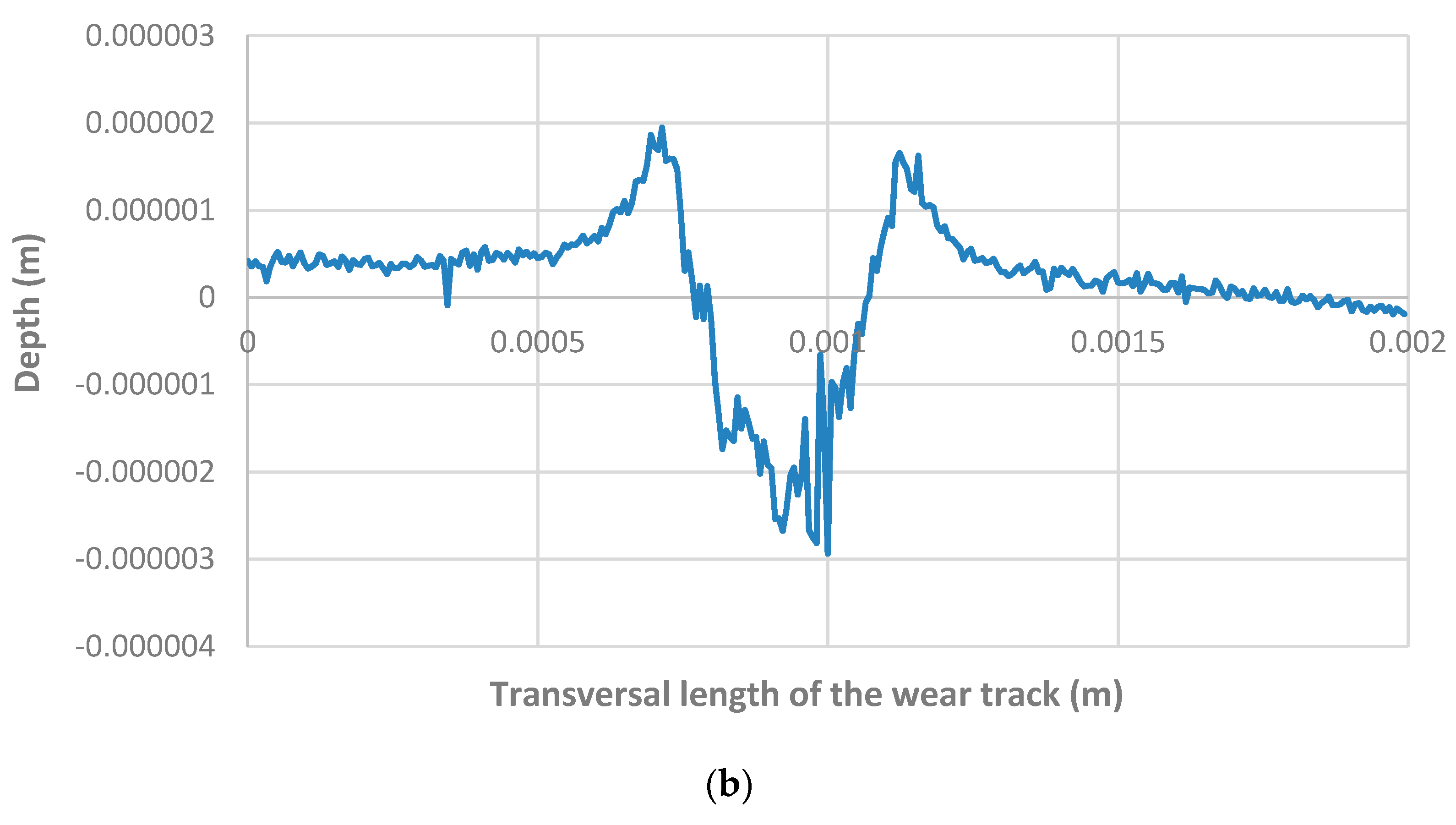
2.2.2. Sliding Indentation Test

The concept of the load-bearing capacity of a coating can be understood as the load applied on a non-conformal contact at which the formation of the first crack starts, thus exposing the integrity of the coating [27]. Under certain complex load conditions, failures can easily arise, in the form of detachment, erosion, corrosion, fragmentation, or crushing of structures with coatings, thus leading to their failure, which can compromise the integrity of the mechanical component where they are applied [27]. The mechanical properties of the substrate can contribute to a change in the carrying capacity of thin coatings. By increasing the hardness of a substrate, it is possible to reduce its deformation, thus relieving the stresses existing at the interface between the substrate and the coating and increasing its load-bearing capacity [22] since the highest tangential stresses occur several tens of micrometers below the film, given the normally applied contact conditions. The creation of cracks in the coating, or located at the interface between the coating and the substrate, represents a problem, as it can lead to the disintegration of large areas of the coating [22]. Therefore, adhesion between the substrate and the coating is one of the main properties for maximizing the carrying capacity of the coating.
In the present research work, the sliding indentation technique was used to measure the sliding friction and to study the load-bearing capacity of the thin coatings. In this technique, a continuous sliding with a constant velocity was performed to a sphere–plane set as the normal force linearly increased (0–100 N). This progressive increase in the normal force corresponds to a maximum contact pressure of 2.49 GPa for the Al2O3 counterbody and 2.16 GPa for the 100Cr6 counterbody, taking into account the Hertzian contact theory. The normal load was applied through the actuation of a helical spring by a high precision linear actuator (1 µm accuracy). The sliding movement is imposed by a second actuator, with precision similar to that used to apply the load, connected to the lower specimen where a three-component load cell is placed in order to measure the normal force and the tangential force during testing. In Figure 4 are identified the main components of the sliding indentation test, while in Figure 5 is shown a schematic illustration of the wear track.

3. Results and Discussion

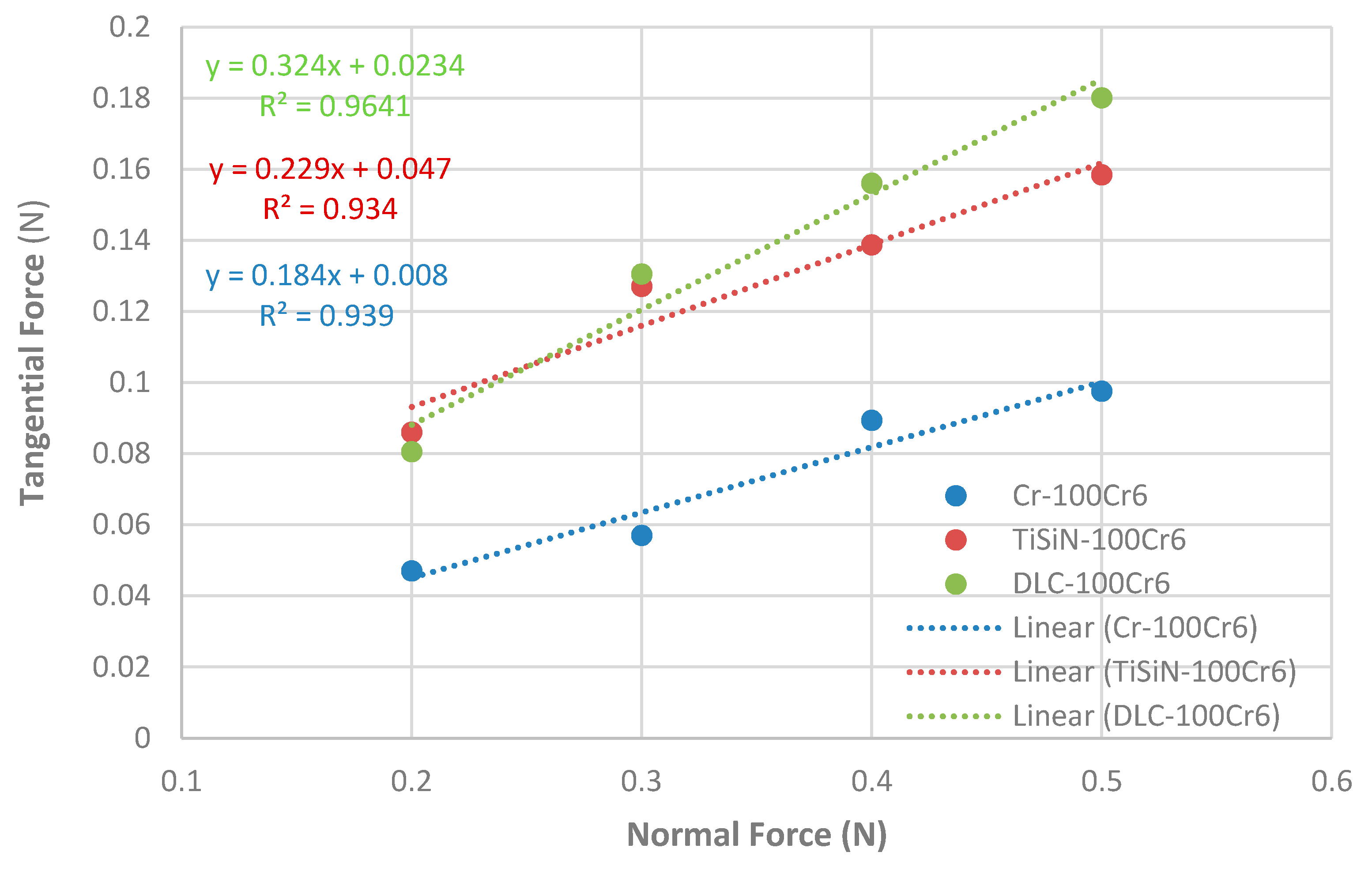
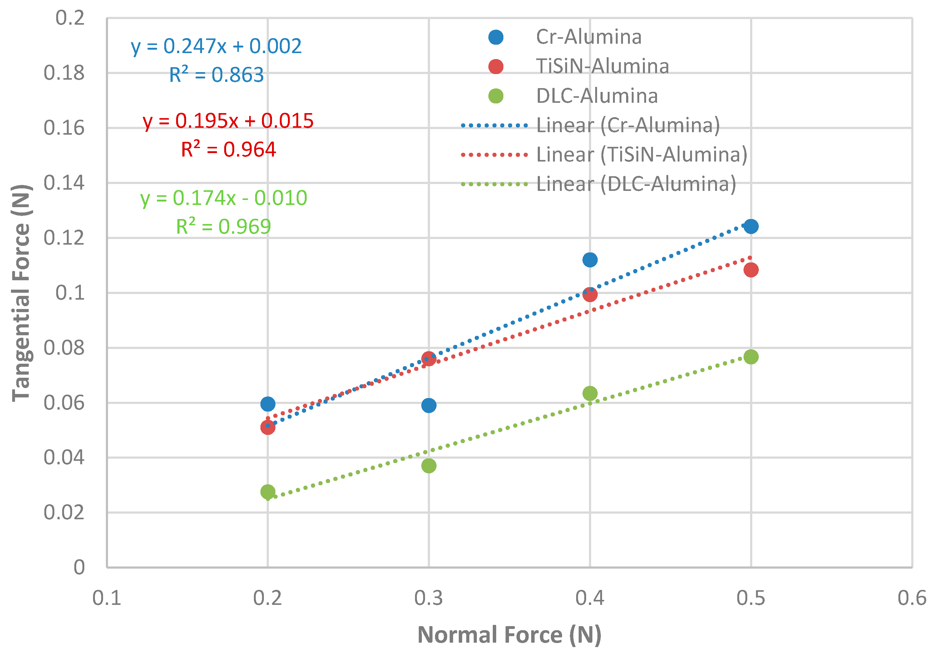
3.1. Determination of Friction through Energy Dissipated in Vibratory Systems

As can be seen in Figure 6, the system response in free vibration is characterized by a vibration with a constant frequency and an amplitude that decreases exponentially with the number of cycles. This behavior allows us to deduce that energy dissipation occurs mainly in the viscous form due to air resistance and energy losses intrinsic to the assembly of the device. The equation of motion corresponding to free vibration can be modeled by an under-damped system in free vibration, having Equation (2) as the solution of the motion. After assessing the rigidy k of the system, by measuring the deformation under static loading, the calculation of the mass of the system, m, and the damping factor, ξ, was achieved by varying their values iteratively in the theoretical Equation (5), and superimposing the theoretical free vibration curves (Figure 6b) with the experimental free vibration curve (Figure 6a) to minimize the square root of the mean square error (RMSE) between them. In this case, m = 0.1453 Kg and ξ = 0.0025 were obtained with RMSE values lower than 10−4, which corresponds to a perfect overlap between the experimental signal and the theoretical equation, as can be seen in Figure 6b.
The natural frequency ωn can be calculated through Equation (5) using the stiffness constant k and the mass m that were previously calculated, obtaining ωn = 186,281 rad/s2.
ω n = k m
Due to the low value of the damping factor ξ, the damped natural frequency ωa will be very similar to the natural frequency ωn. This value was calculated using Equation (6), where ωa appears as a function of the natural frequency ωn and the damping factor ξ already calculated. A value of ωa = 186.04 rad/s2 was obtained.
ω a = ω n 1 ξ 2  
Finally, it is necessary to calculate the damping constant C through Equation (7), where a value of 0.1353 [N·s/m] was obtained.
C = 2 ξ k m  
Thus, it is possible to identify all the characteristic constants of the experimental model, which are summarized in Table 2.
Figure 7 shows the evolution of the displacement with time for the free vibration motion with frictional energy dissipation for the case of the TiSiN coating sliding against the Al2O3 sphere under 0.2 N applied normal force. For this contact conditions, a coefficient of friction of 0.25 was obtained.
Figure 8 and Figure 9 show the results obtained in the measurement of friction for the different systems, composed of three different types of coatings and two different spherical counterbodies, 100Cr6 and Al2O3, respectively. For each measurement, a change in the position of the specimen and the counterbody was made in order to ensure that the wear induced by the previous test did not interfere with the measurement of friction in the subsequent test.
The values of the friction coefficients (µ) obtained for the different coatings are summarized in Table 3 together with the respective linear correlation indices (R2) and standard deviations (STDEV).
As shown in Figure 8 and Figure 9, the friction coefficient thus corresponds to the slope value of the linear trend line (dashed lines) adjusted to the values of normal force and tangential force. To assess the quality of the linear fit of the trend line, the linear correlation index (R2) was used. The closer this value is to unity, the greater the similarity between the friction coefficient obtained by the linear model and the friction coefficients obtained experimentally. In general, we can conclude that the experimental results presented show high linearity. R2 values higher than 0.93 were obtained in all tests except in the case of the test between the Cr coating and the Al2O3 counter body, which presented an R2 value of 0.86.
Regarding the standard deviation values, we can conclude that relatively high values were obtained in the Cr/Al2O3 and TiSiN/100Cr6 tests, 0.044, and 0.056, respectively. For the other tests, these values were approximately 0.02.
By analyzing the experimental results, we can conclude that the results obtained follow the trend of the linear model of Coulomb—Amontons in determining the value of the coefficient of friction. For all cases, it is visible that the linear fit line to the experimentally obtained data have an intercept at the origin different from zero, which means that even if the normal force applied to the system is null, there will always be a friction force, even that their values are extremely small. This phenomenon can be explained by the existence of the friction adhesive component. At the contact interface between the counter-body sphere and the flat sample, bonding bridges are created that enhance the adhesion between the two bodies. The experimental results obtained thus allow us to conclude that the counter-body material has a strong influence on the friction coefficient observed for each type of coating. In the case of TiSiN and DLC coatings, higher friction coefficient values were recorded in tests with 100Cr6 counterbody than in tests with Al2O3 counterbody.
The Cr coating showed an inverse trend, showing an increase in the coefficient of friction in the tests performed with the Al2O3 sphere. It was also observed that in the tests with 100Cr6 counter-body, the DLC-type coatings presented the highest friction coefficient, followed by the TiSiN and finally the Cr coatings. Regarding the tests performed with the Al2O3 counterbody, there was a complete inversion of the friction coefficients, with the coating that presented the highest friction Cr followed by TiSiN and DLC.

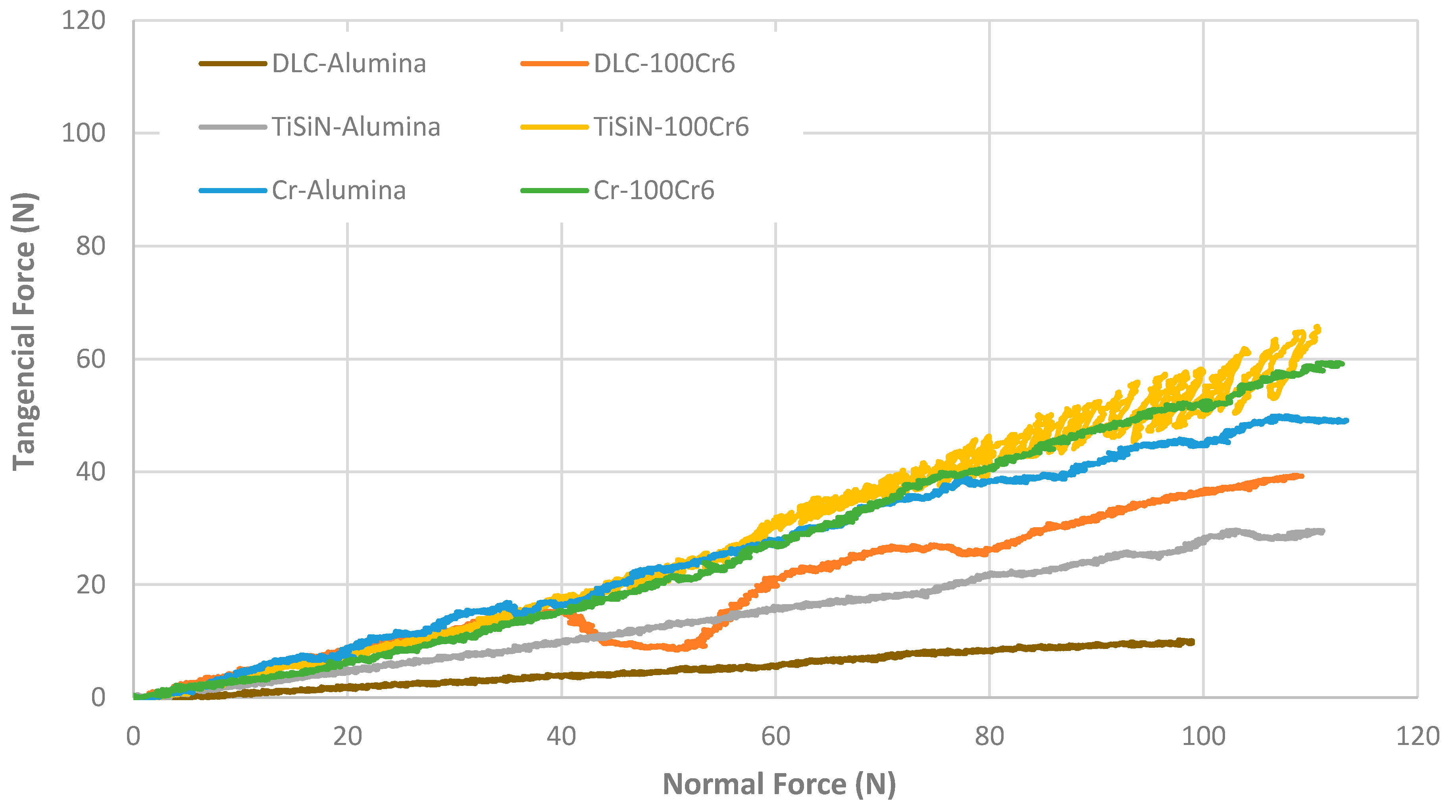
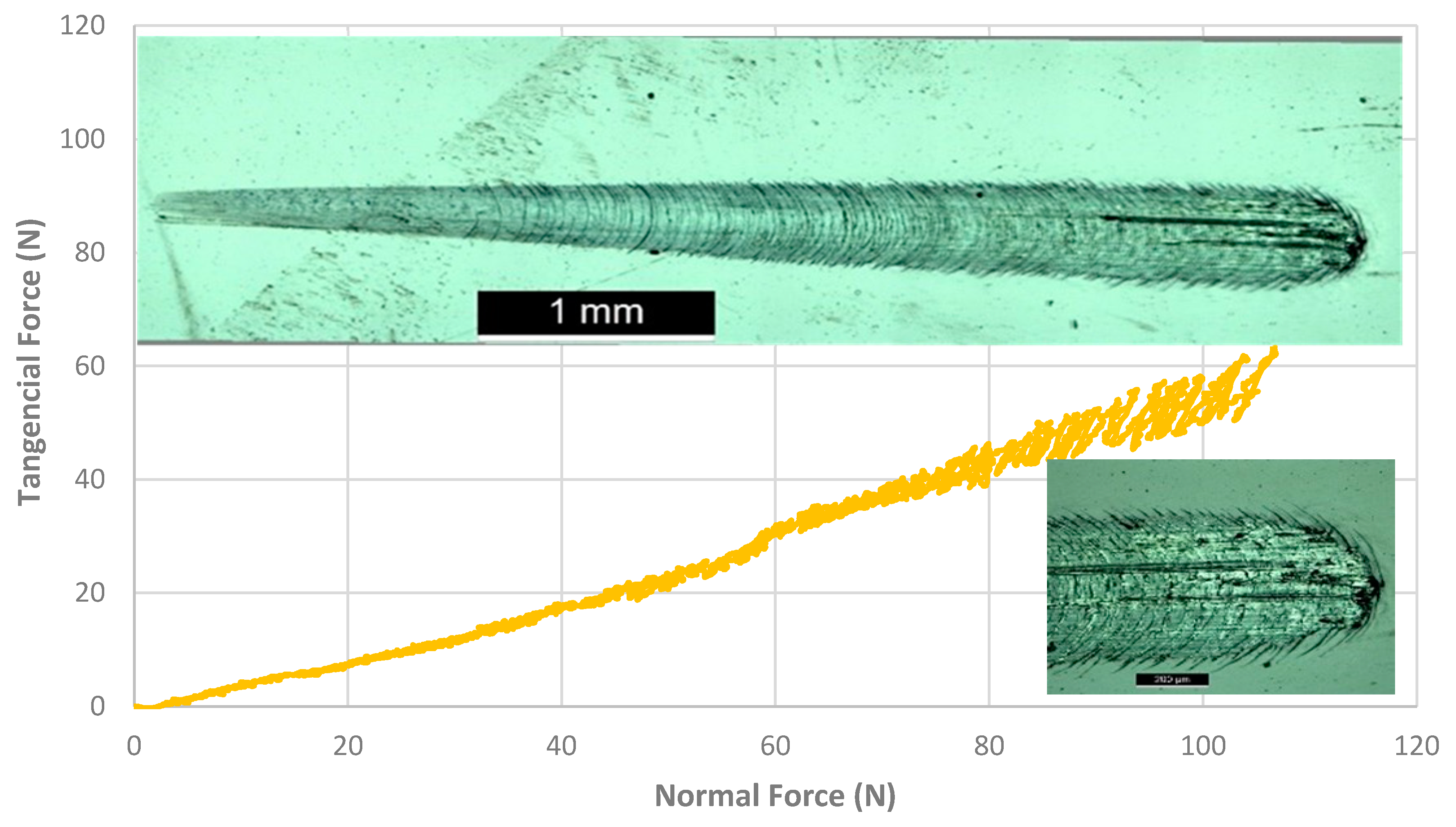
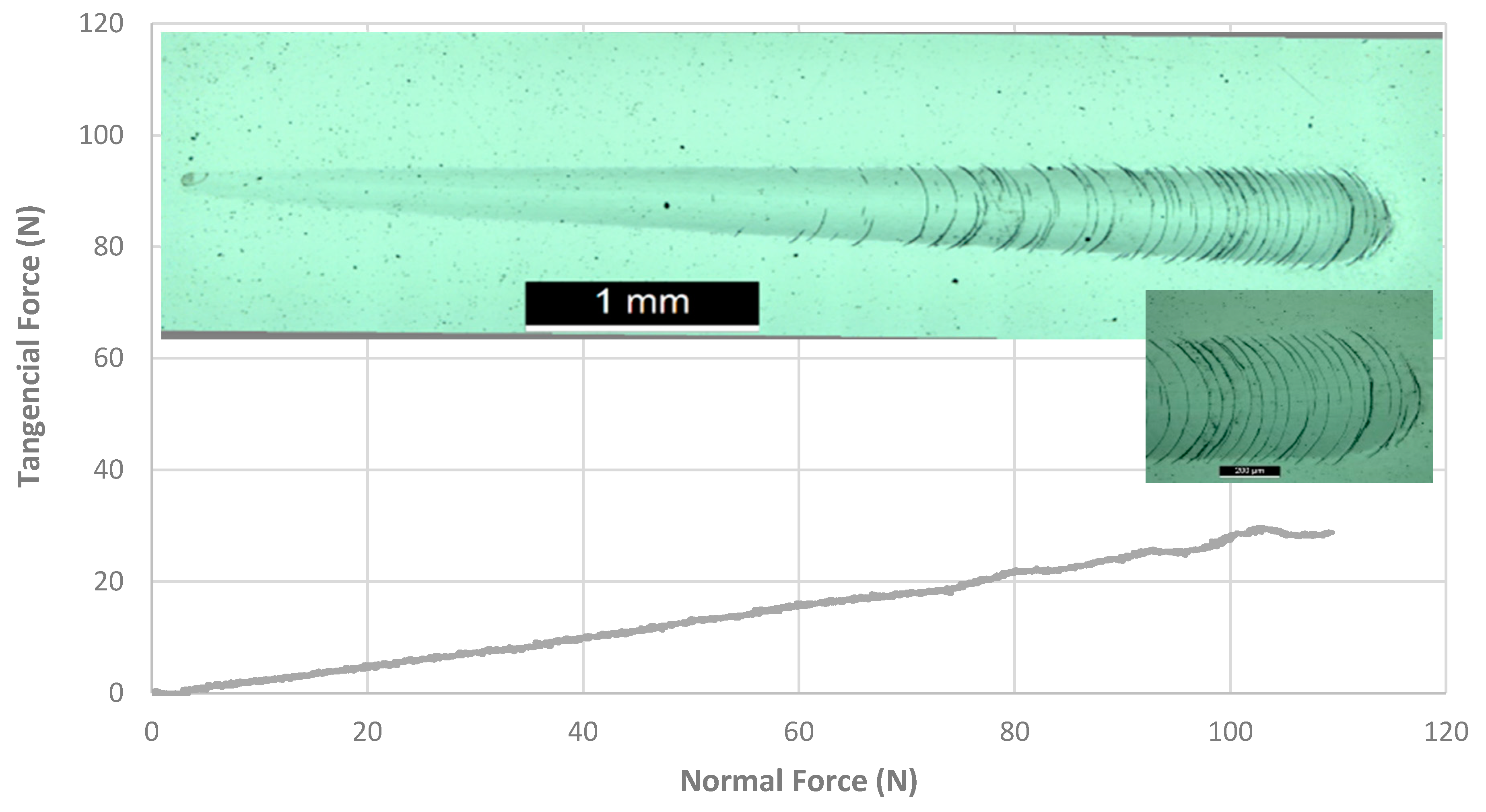
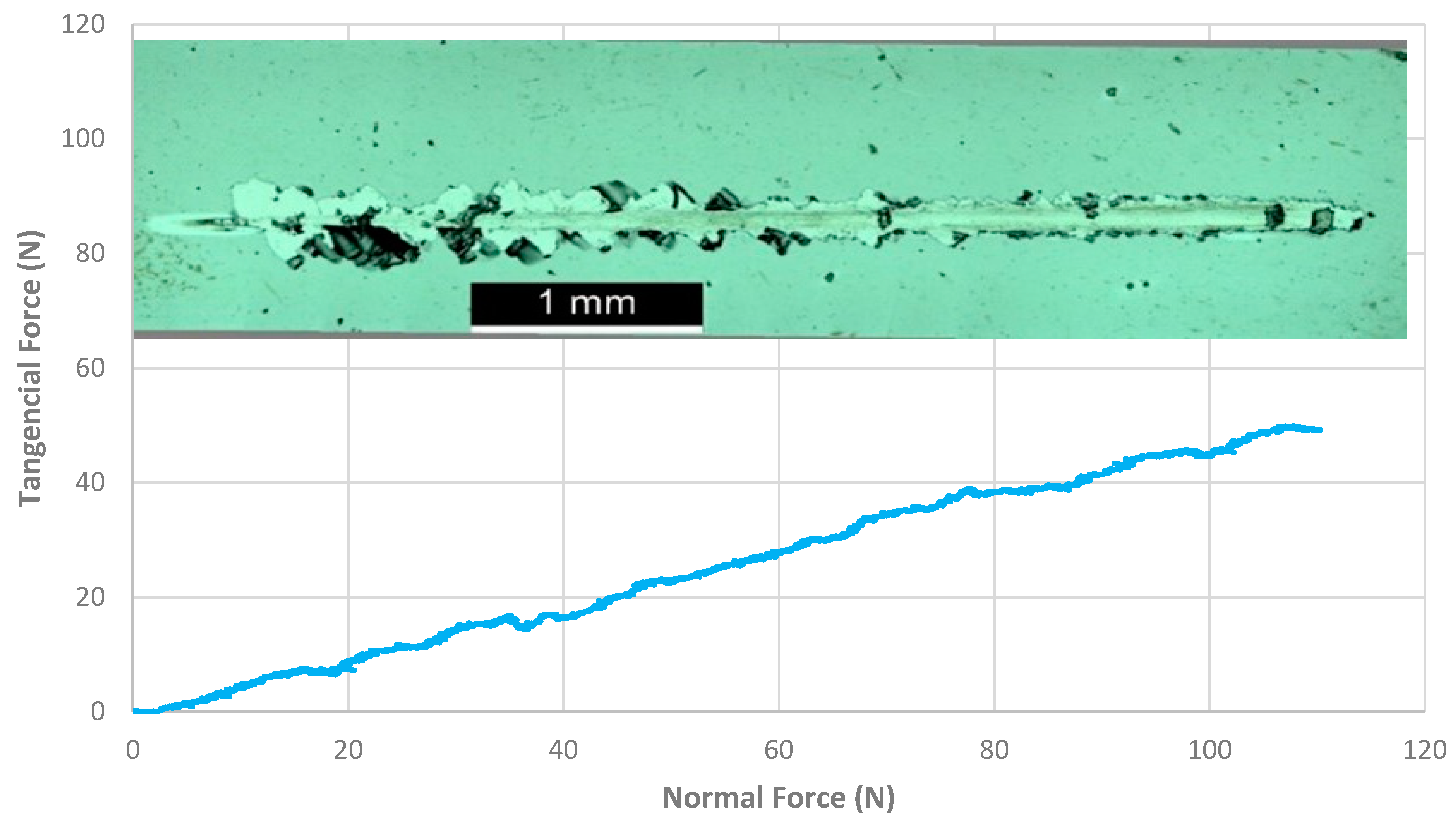
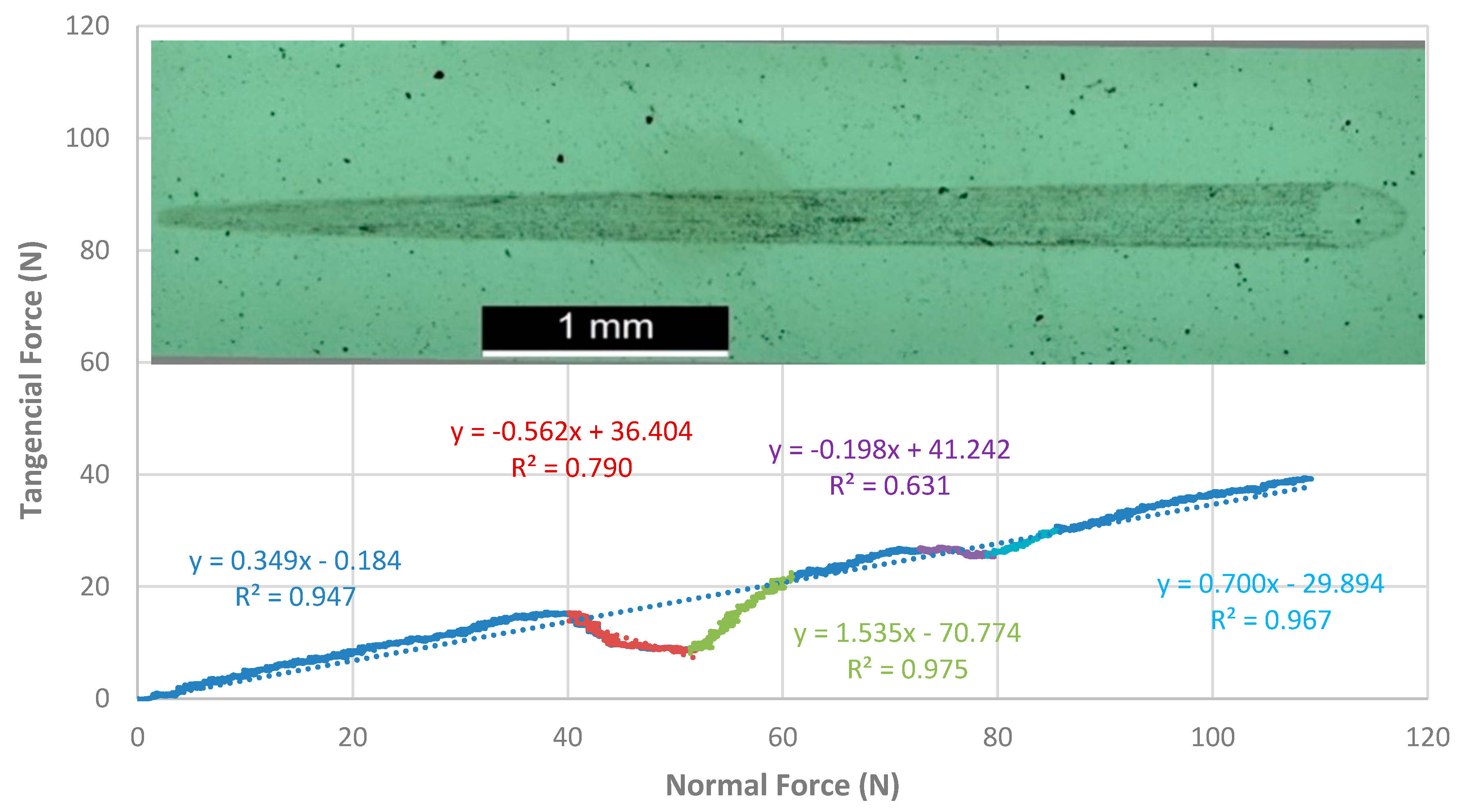
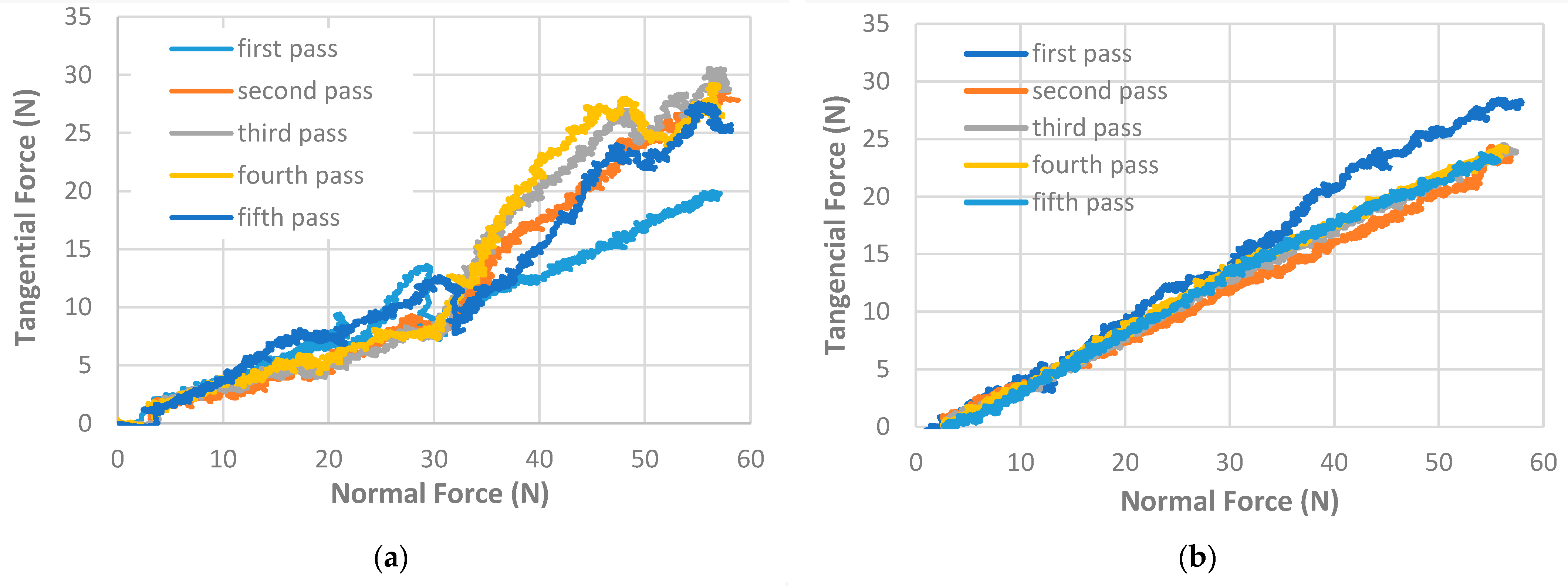
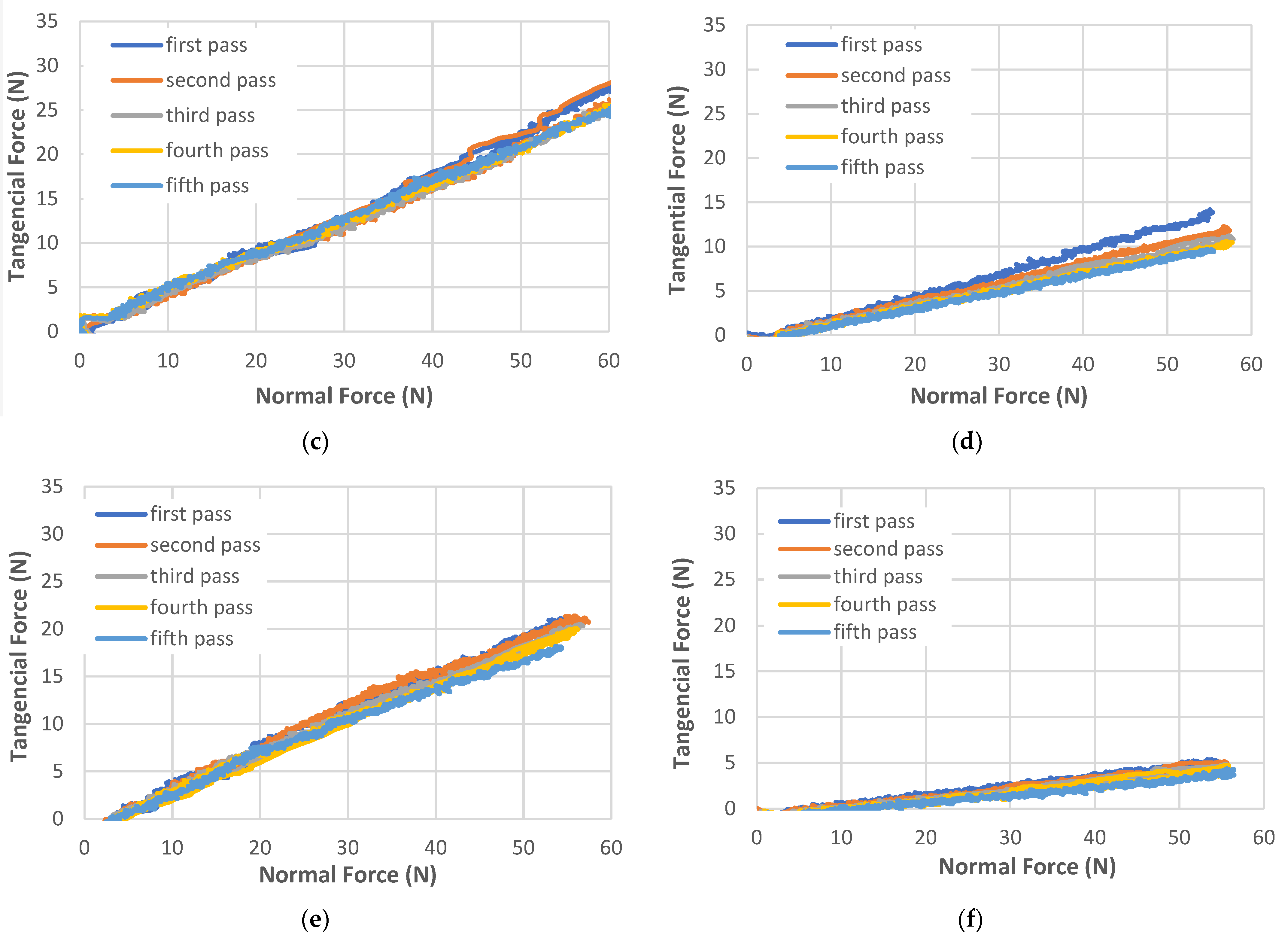
3.2. Determination of the Load-Bearing Capacity through the Sliding Indentation Test

Single passage
In Figure 10, the curves of the evolution of the tangential force with the increase of the applied normal force are presented for the different systems constituted by the three different types of coatings and two counterbodies. By observing Figure 10, it is possible to conclude that the tribological pair that presented the lowest coefficient of friction was the system constituted by DLC/Al2O3 (lower slope). This test showed a very tenuous wear track, and no damage to the film was observed. It was also verified that the tests carried out with the Al2O3 counterbodies always presented lower coefficient of friction values compared to the tests in which the 100Cr6 counterbodies were used. Most likely, the fact that the Al2O3 ceramic sphere has a much higher hardness than the 100Cr6 steel sphere may have contributed to this behavior. Regarding the tribological pairs of Cr/100Cr6 and Cr/Al2O3, they were the ones that presented a higher slope and correspondingly a higher coefficient of friction values. As a result of the microscopic observation carried out on the respective wear tracks, it was possible to ascertain that many of the coatings analyzed suffered various failure mechanisms. In order to study the registered failure mechanisms, an individual analysis was carried out for each of the tribological tests.
Figure 11 shows the test corresponding to the TiSiN/100Cr6 tribological pair, which is one of the systems that presented the highest coefficient of friction (along with the Cr/100Cr6 system) when compared to the other tribological pairs. For normal loads above 80 N, it was possible to observe a great instability in the evolution of the tangential force with large amplitude oscillations. Most likely, there was film breakage with cracking due to bow deformation wave as well as a possible transfer of material between the specimen and the counter-body, resulting in some accumulation of debris in the wear track, giving rise to stick-slip behaviour for normal loads greater than approximately 80 N.
Figure 12 shows the test corresponding to the TiSiN/Al2O3 tribological pair. As shown in Figure 12, and despite its low coefficient of friction, the TiSiN/Al2O3 test showed the damage of part of the film with small superficial bursts for normal loads above 70 N, without any accumulation of debris on the wear track. In this case, it was impossible to observe any material transfer trace between the sample and the counterbody. The small superficial bursts caused small fluctuations in the evolution of the tangential force with the increase of the normal force.
Figure 13 shows the test corresponding to the Cr/Al2O3 tribological pair. Both tests corresponding to systems composed of Cr/100Cr6 and Cr/Al2O3 showed destruction of the coating, but in the latter, the damage suffered was more evident. As shown in Figure 13, delamination of the film was verified with lifting and pulling out of large amounts of material from the coating to very low values of the normal load (<20 N). For higher loads, lateral delaminations of smaller amounts of material were verified, with some accumulation of debris in the wear track.
Figure 14 shows the test corresponding to the tribological pair DLC/100Cr6. Unlike the test corresponding to the tribological pair DLC/Al2O3, for which it was difficult to identify the wear track, this test presented a shaded zone, as illustrated in Figure 14. Since the evolution of tangential force vs. the normal force showed some notable abrupt variations, isolated parts of the curve and determined the slope of the respective trend lines. It is thus possible to verify that at the beginning of the test, up to 40 N, there was a linear evolution of the tangential force with an increase in the normal force, corresponding to a coefficient of friction of approximately 0.348. There was then a sharp fall in the trend line followed by a further rise with a coefficient of friction of approximately 1.535. Around 75 N, there was a new drop and sudden increase in the friction coefficient with a value of approximately 0.700 until reaching the initial value of 0.348 for loads above 85 N.
Multi passages
In addition to this first analysis, it was carried out a study to find out the influence of the number of passages of the counterbody against the same wear track. In this study, five consecutive passages were carried out, exactly on the same wear track, with a linear increase of normal force from 0 up to 50 N for all tribological pairs. The results of these sliding indentation tests can be seen in Figure 15.
Through the analysis of Figure 15, it is possible to conclude that in certain tribological pairs, there were significant modifications in the linearity of the evolution of tangential force as a progressive increase in normal force, revealing possible points of breakage of the coatings. This was the case of the coatings corresponding to the Cr/100Cr6 and Cr/Al2O3 tribological pairs.
In other cases, it was also possible to observe that after the first passage, there was a decrease in the slope, corresponding to a decrease in the coefficient of friction. That was the case of the two coatings of the TiSiN/100Cr6 and TiSN/Al2O3 system.
The coatings of the DLC/100Cr6 and DLC/Al2O3 system did not show a large variation in the relationship between the tangential force and the normal force from passage to passage. Of all the coatings analyzed, the Cr coatings showed the highest friction values, followed by the TiSiN coatings and the lowest values, the DLC coatings.
In Table 4 are presented the various coefficients of friction obtained from the sliding indentation tests.
As an example, in Figure 16 it is possible to observe the evolution of the tangential force as the increase of the normal force for the first passage of the system composed of Cr/100Cr6 tribological pair and the respective optical micrograph. By analysis of Figure 16, we can conclude that in the first passage, a phenomenon of adhesive type is very likely to be verified between the counterbody and the coating for normal forces between 20 and 30 N. Such a conclusion is due to the fast increase of the coefficient of friction from values of about 0.334 to 1.229. Beyond this trend, and for normal loads of the order of 30 N, it follows a one-hundredth of the friction that corresponds to the moment when the addition was broken, being then newly normalized to the relationship between the tangential force and the normal force, with values of friction coefficient of approximately 0.394.
Sliding indentation tests cause plastic deformation on the surface. There is a deformation in depth in the area where the indentation occurs and a composite deformation by lifting the material from the edges that gives a wear track with a special impact on the final area of the indentation, where the standard loads are higher. This last phenomenon is the consequence of the dragging of material due to adhesion between the coating and the counterbody.
In Figure 17 is visible a 3D profile of the wear test carried out by tribological pair TiSiN/100Cr6.
In Figure 18a is visible the longitudinal profile of the entire length of the wear track where it can be concluded that the maximum depth of indentation is about 3 µm for a maximum load of 100 N, and the plastic deformation in front of the track creates a lift of about 3.5 µm. In Figure 18b, the cross-sectional profile of the deepest area of the indentation is represented, where there is also an accentuated uplift of the surface adjacent to the wear track.

4. Conclusions

In this research work, two complementary methods are proposed to select coatings for mechanical components, particularly during industrial equipment refurbishment. Concerning the experimental techniques, the following conclusions can be drawn:
  • The proposed test method to measure friction, based on free vibration movement, allowed to achieve accurate results very quickly and with samples of simple geometry.
  • The sliding indentation technique with a single passage allows the characterization of the maximum load bearing without damage.
  • In addition, sliding indentation with multiple passage, in the same track, allows to apprize the endurance performance of the different coatings.
Concerning the behavior of the tested coatings, it was possible to conclude:
  • DLC coatings showed lower friction following TiSiN and Cr coatings. The following relationship was determined: µDLC <µTiSiN <µCr.
  • The Young’s modulus given results on a similar rank.
  • A great influence of the counter-body was observed. The tribological pairs for those who used the Al2O3 sphere always evidenced lower friction than the pairs for those who used a 100Cr6 sphere, for both tests. Funding: this research received no external funding.

Author Contributions

Conceptualization, L.V., F.F., J.C.O., and A.R.; methodology, L.V., and A.R.; software, L.V., and A.R.; validation, L.V., F.F., J.C.O., and A.R.; formal analysis, L.V., and A.R.; investigation, L.V., F.F., J.C.O., and A.R.; data curation, L.V., and A.R.; writing—original draft preparation, L.V., F.F., J.C.O., and A.R.; writing—review and editing, L.V., and A.R.; supervision L.V., and A.R. All authors have read and agreed to the published version of the manuscript.

Funding

This research received no external funding.

Data Availability Statement

The data presented in this study are available on request from the corresponding author. The data are not publicly available due to privacy.

Acknowledgments

This research is sponsored by FEDER funds through the program COMPETE—Programa Operacional Factores de Competitividade—and by national funds through FCT—Fundação para a Ciência e a Tecnologia –, under the project UIDB/00285/2020 and DLCs HardRings (AAC n.º 02/SAICT/2017, project n.º 29122).

Conflicts of Interest

The authors declare no conflict of interest.

References

  1. Huang, Z.P.; Sun, Y.; Bell, T. Friction behaviour of TiN, CrN and (TiAl)N coatings. Wear 1994, 173, 13–20. [Google Scholar] [CrossRef]
  2. Holmberg, K.; Siilasto, R.; Laitinen, T.; Andersson, P.; Jäsberg, A. Global energy consumption due to friction in paper machines. Tribol. Int. 2013, 62, 58–77. [Google Scholar] [CrossRef]
  3. Holmberg, K.; Kivikytö-Reponen, P.; Härkisaari, P.; Valtonen, K.; Erdemir, A. Global energy consumption due to friction and wear in the mining industry. Tribol. Int. 2017, 115, 116–139. [Google Scholar] [CrossRef]
  4. Holmberg, K.; Erdemir, A. Influence of tribology on global energy consumption, costs and emissions. Friction 2017, 5, 263–284. [Google Scholar] [CrossRef]
  5. Michailidis, N. Variations in the cutting performance of PVD-coated tools in milling Ti6Al4V, explained through temperature-dependent coating properties. Surf. Coat. Technol. 2016, 304, 325–329. [Google Scholar] [CrossRef]
  6. Silva, F.; Martinho, R.; Andrade, M.; Baptista, A.; Alexandre, R. Improving the wear resistance of moulds for the injection of glass fibre–reinforced plastics using PVD coatings: A comparative study. Coatings 2017, 7, 28. [Google Scholar] [CrossRef] [Green Version]
  7. Holmberg, K.; Ronkainen, H.; Matthews, A. Tribology of thin coatings. Ceram. Int. 2000, 26, 787–795. [Google Scholar] [CrossRef]
  8. Bellardita, M.; Di Paola, A.; Yurdakal, S.; Palmisano, L. Preparation of Catalysts and Photocatalysts Used for Similar Processes. In Heterogeneous Photocatalysis: Relationships with Heterogeneous Catalysis and Perspectives; Marcí, G., Palmisano, L., Eds.; Springer: Berlin/Heidelberg, Germany, 2019; pp. 105–110. [Google Scholar]
  9. Cardoso, F.J.G. Desempenho de revestimentos de carbono tipo-diamante (produzidos pela tecnologia inovadora Ne-HIPIMS) sob diferentes regimes de lubrificação. Master’s Thesis, Universidade de Coimbra, Coimbra, Portugal, 2013. Unpublished. [Google Scholar]
  10. Hughes, M. What is HIPIMS? High Power Impulse Magnetron Sputtering. Semicore. 28 October 2016. Available online: http://www.semicore.com/news/93-what-is-hipims (accessed on 1 October 2021).
  11. Kouznetsov, V.; Macak, K.; Schneider, J.M.; Helmersson, U.; Petrov, I. A novel pulsed magnetron sputter technique utilizing very high target power densities. Surf. Coat. Technol. 1999, 122, 290–293. [Google Scholar] [CrossRef]
  12. Ferreira, E.S. Pulverização catódica magnetrão com impulsos de alta potência (HiiPIMS) em modo DOMS. Master’s Thesis, Universidade de Coimbra, Coimbra, Portugal, 2020. Unpublished. [Google Scholar]
  13. Sarakinos, K.; Alami, J.; Konstantinidis, S. High power pulsed magnetron sputtering: A review on scientific and engineering state of the art. Surf. Coat. Technol. 2010, 204, 1661–1684. [Google Scholar] [CrossRef]
  14. Robertson, J. Diamond-like amorphous carbon. Mater. Sci. Eng. R Rep. 2002, 37, 129–281. [Google Scholar] [CrossRef] [Green Version]
  15. Erdemir, A.; Bindal, C.; Pagan, J.; Wilbur, P. Characterization of transfer layers on steel surfaces sliding against diamond-like hydrocarbon films in dry nitrogen. Surf. Coat. Technol. 1995, 76, 559–563. [Google Scholar] [CrossRef]
  16. Grill, A. Tribology of diamondlike carbon and related materials: An updated review. Surf. Coat. Technol. 1997, 94, 507–513. [Google Scholar] [CrossRef]
  17. Yazdi, M.A.; Lomello, F.; Wang, J.; Sanchette, F.; Dong, Z.; White, T.; Wouters, Y.; Schuster, F.; Billard, A. Properties of TiSiN coatings deposited by hybrid HiPIMS and pulsed-DC magnetron co-sputtering. Vacuum 2014, 109, 43–51. [Google Scholar] [CrossRef]
  18. Vaz, F.; Rebouta, L.; Goudeau, P.; Girardeau, T.; Pacaud, J.; Riviere, J.P.; Traverse, A. Structural transitions in hard Si-based TiN coatings: The effect of bias voltage and temperature. Surf. Coat. Technol. 2001, 146, 274–279. [Google Scholar] [CrossRef]
  19. Vepřek, S.; Reiprich, S. A concept for the design of novel superhard coat-ings. Thin Solid Film. 1995, 268, 64–71. [Google Scholar] [CrossRef]
  20. Kubart, T.; Aijaz, A.; Andersson, J.; Ferreira, F.; Oliveira, J.C.; Sobetkii, A.; Parau, A.C.; Vitelaru, C. High power impulse magnetron sputtering of diamond-like carbon coatings. J. Vac. Sci. Technol. A Vac. Surf. Film. 2020, 38, 043408. [Google Scholar] [CrossRef]
  21. Ian Hutchings, Philip Shipway, Tribology: Friction and Wear of Engineering Materials, 2nd ed.; Elsevier: Amsterdam, The Netherlands, 2016.
  22. Wang, C.T.; Hakala, T.J.; Laukkanen, A.; Ronkainen, H.; Holmberg, K.; Gao, N.; Wood, R.J.; Langdon, T.G. Langdon. An investigation into the effect of substrate on the load-bearing capacity of thin hard coatings. J. Mater. Sci. 2016, 51, 4390–4398. [Google Scholar] [CrossRef]
  23. Carvalho, A.L.; Vilhena, L.M.; Ramalho, A. Study of the frictional behavior of soft contact lenses by an innovative method. Tribol. Int. 2021, 153, 106633. [Google Scholar] [CrossRef]
  24. Carneiro, E.R.; Coelho, A.S.; Amaro, I.; Paula, A.B.; Marto, C.M.; Saraiva, J.; Ferreira, M.M.; Vilhena, L.; Ramalho, A.; Carrilho, E. Mechanical and Tribological Characterization of a Bioactive Composite Resin. Appl. Sci. 2021, 11, 8256. [Google Scholar] [CrossRef]
  25. Rigaud, E.; Perret-Liaudet, J.; Belin, M.; Joly-Pottuz, L.; Martin, J.M. An original dynamic tribotest to discriminate friction and viscous damping. Tribol. Int. 2010, 43, 320–329. [Google Scholar] [CrossRef] [Green Version]
  26. Le Bot, A.; Scheibert, J.; Vasko, A.A.; Braun, O.M. Relaxation tribometry: A generic method to identify the nature of contact forces. Tribol. Lett. 2019, 67, 53. [Google Scholar] [CrossRef] [Green Version]
  27. Feng, J.L.; Qin, Y. Load bearing capacity investigation and coating failure mechanism for coated spur gears. Appl. Mech. Mater. 2014, 446, 491–496. [Google Scholar] [CrossRef]
Figure 1. Picture showing the different components from the dynamic oscillating tribometer used during experiments.
Electronics 11 00296 g001
Figure 2. Scheme exemplifying the system used to measure friction and composed of mass–spring–shock absorber subject to Coulomb friction.
Electronics 11 00296 g002
Figure 3. Flowchart of the experimental protocol used to measure the coefficient of friction [23].
Electronics 11 00296 g003
Figure 4. Schematic picture showing the main components of the sliding indentation test.
Electronics 11 00296 g004
Figure 5. Schematic illustration of the wear track caused by the sliding indentation test: (a) top view, showing the gradual area increase due to the load increase in the sliding direction; (b) cross-section view, showing the built-up areas (A1 + A2) and area of the scratch (A3) [24].
Electronics 11 00296 g005aElectronics 11 00296 g005b
Figure 6. Evolution of the displacement with time for the free vibration motion (without contact): (a) experimental curve; (b) overlap between the experimental and theoretical curve (truncated at 2 s, so the overlap is visible).
Electronics 11 00296 g006aElectronics 11 00296 g006b
Figure 7. Evolution of the displacement with time for the free vibration motion with frictional energy dissipation, showing the experimental curve (blue line) and the theoretical curve (orange line). TiSiN coating sliding against Al2O3 sphere under 0.2 N applied normal force.
Electronics 11 00296 g007
Figure 8. Evolution of the tangential force with the normal force for the three different coatings sliding against 100Cr6 sphere.
Electronics 11 00296 g008
Figure 9. Evolution of the tangential force with the normal force for the three different coatings sliding against the Al2O3 sphere.
Electronics 11 00296 g009
Figure 10. Evolution of the tangential force with the rise of normal force for the three different coatings sliding against Al2O3 and 100Cr6 spheres obtained through the sliding indentation tests for one single pass.
Electronics 11 00296 g010
Figure 11. Evolution of the tangential force with the normal force for the TiSiN/100Cr6 tribological pair for one single pass and optical microscopy of the wear track.
Electronics 11 00296 g011
Figure 12. Evolution of the tangential force with the normal force for the TiSiN/Al2O3 tribological pair for one single pass and optical microscopy of the wear track.
Electronics 11 00296 g012
Figure 13. Evolution of the tangential force with the normal force for the Cr/Al2O3 tribological pair for one single pass and optical microscopy of the wear track.
Electronics 11 00296 g013
Figure 14. Evolution of the tangential force with the normal force for the DLC/100Cr6 tribological pair for one single pass and optical microscopy of the wear track.
Electronics 11 00296 g014
Figure 15. Evolution of the tangential force with the normal force for the following tribological pairs for multi passages (five passages) and applied load varying from 0 to 50 N: (a) Cr/100Cr6, (b) Cr/Al2O3, (c) TiSiN/100Cr6, (d) TiSiN/Al2O3, (e) DLC/100Cr6, (f) DLC/Al2O3.
Electronics 11 00296 g015aElectronics 11 00296 g015b
Figure 16. Evolution of the tangential force with the normal force for the Cr/100Cr6 tribological pair for one single pass and optical microscopy of the wear track.
Electronics 11 00296 g016
Figure 17. The 3D profile from the wear track of the tribological pair TiSiN/100Cr6 for one single pass (0–100 N).
Electronics 11 00296 g017
Figure 18. The 2D profiles from the wear track of the tribological pair TiSiN/100Cr6 for one single pass (0–100 N): (a) longitudinal length of the wear track, (b) transversal length of the wear track.
Electronics 11 00296 g018aElectronics 11 00296 g018b
Table 1. Mechanical properties of specimens produced with six different coatings from three different coating families used in the tribological tests. All six specimens were tested against 100Cr6 and Al2O3 spheres. The substrates were made from M2 high-speed steel.
SpecimensDesignationE [GPa]Hardness [GPa]Ra [μm]Thickness [nm]
1TiSiN1250330.11161000
2Cr1285180.1436890
3DLC1200220.1103800
4TiSiN2230230.11631000
5Cr2285180.1134890
6DLC2200150.1179800
Table 2. Constants from the experimental model.
m
[kg]
c
[N·s/m]
k
[N/m]
ωn
[rad/s2]
0.14530.13535042186.28
Table 3. Coefficient of friction values for the tribological pairs constituted by the three different thin coatings and the 100Cr6 and Al2O3 counterbodies obtained through the vibration technique.
Tribological PairCounterbody
Thin Coatings100Cr6Al2O3
µ ± STDEVR2µ ± STDEVR2
Cr0.18 ± 0.020.940.25 ± 0.040.86
TiSiN0.23 ± 0.060.930.20 ± 0.020.96
DLC0.32 ± 0.030.960.17 ± 0.020.97
Table 4. Coefficient of friction values for the six tribological pairs constituted by the three different thin coatings and the 100Cr6 and Al2O3 counterbodies obtained through the sliding indentation tests.
Tribological PairCounterbody
Thin Coatings100Cr6Al2O3
µ
Cr0.471 0.539
TiSiN0.548 0.272
DLC0.348 0.108
Publisher’s Note: MDPI stays neutral with regard to jurisdictional claims in published maps and institutional affiliations.

