Article

A 3D Scene Information Enhancement Method Applied in Augmented Reality

1
Shenyang Institute of Engineering, Shenyang 110136, China
2
Shenyang Institute of Automation, Shenyang 110136, China
*
Authors to whom correspondence should be addressed.
Electronics 2022, 11(24), 4123; https://doi.org/10.3390/electronics11244123
Submission received: 3 November 2022 / Revised: 2 December 2022 / Accepted: 2 December 2022 / Published: 10 December 2022
(This article belongs to the Section Computer Science & Engineering)

Abstract

:
Aiming at the problem that the detection of small planes with unobvious texture is easy to be missed in augmented reality scene, a 3D scene information enhancement method to grab the planes for augmented reality scene is proposed based on a series of images of a real scene taken by a monocular camera. Firstly, we extract the feature points from the images. Secondly, we match the feature points from different images, and build the three-dimensional sparse point cloud data of the scene based on the feature points and the camera internal parameters. Thirdly, we estimate the position and size of the planes based on the sparse point cloud. The planes can be used to provide extra structural information for augmented reality. In this paper, an optimized feature points extraction and matching algorithm based on Scale Invariant Feature Transform (SIFT) is proposed, and a fast spatial planes recognition method based on a RANdom SAmple Consensus (RANSAC) is established. Experiments show that the method can achieve higher accuracy compared to the Oriented Fast and Rotated Brief (ORB), Binary Robust Invariant Scalable Keypoints (BRISK) and Super Point. The proposed method can effectively solve the problem of missing detection of faces in ARCore, and improve the integration effect between virtual objects and real scenes.

1. Research Background

Augmented reality technology is based on the integration of computer graphics, human–computer interaction and other technologies [1]. With the help of cameras, it displays more information by adding virtual objects to the real scene to enhance people’s understanding of the real world. Augmented reality technology has been widely applied in many areas, such as medical treatment, industry, entertainment and so on [2,3,4,5,6]. In recent years, augmented reality technology has been developed rapidly. Google and Apple, the two largest mobile phone companies in the world, have launched augmented reality development packages ARCore and ARKit based on the Android system and iOS system, respectively, which makes augmented reality technology popular in daily life and able to obtain more opportunities for its application.
The core technology of augmented reality is the seamless integration of virtual objects and real scenes. “Confuse the false with the true” has always been the ultimate goal of researchers in the field of augmented reality. The 3D registration technology is the core technology to improve the realism of augmented reality. Its essence is to properly place the virtual object into the real scene, so that it can be more integrated into the real scene. Therefore, the 3D reconstruction of the real scene structure is very important.
The 3D reconstruction method of a real scene is based on 3D data acquisition equipment or 2D images. The 3D data acquisition equipment includes a RGB-D camera, 3D scanner, LIDAR and so on. The equipment can acquire the depth data of the structure of the scene directly, which can be used to generate the 3D structure of the scene. Kinect is a represent 3D data acquisition equipment from Microsoft. Kinect fusion [7] can get the dense point cloud of the scene in real time and build the 3D structure. KinectFusion has been developed by many researchers [8,9,10]. The 3D reconstruction based on 3D data acquirement equipment has been very efficient and accurate, but cannot be applied widely because of the expensive equipment.
The 3D reconstruction method of a real scene based on images does not need equipment besides cameras, so it has wider application prospects. Many studies have concentrated on this field [11,12,13]. Goesele proposed the Multi-View Stereo (MVS) algorithm [14], which can weaken the influence of illumination to achieve a good reconstruction effect. Furukawa proposed the Patch-Multi-View Stereo (PMVS) algorithm [15], which can build the 3D details in a specific area. Snvaley proposed the Structure from Motion (SFM) algorithm [16], which can build the 3D structure from a serials of unordered images. Many works come from these classical algorithms [17,18,19,20,21,22,23].
Normally, the virtual objects from augmented reality are placed on a plane in the real scene. In most situations, we do not need to build all the 3D structures of a scene. Instead, we only need to recognize the planes where the virtual objects can be put on. Therefore, to recognize planes from the real scene is a very important research topic in the field of augmented reality.
At present, the plane recognition method used in augmented reality has certain recognition accuracy, but there are also some deficiencies. For example, the plane position recognition is not accurate enough, which makes it easy to produce the phenomenon of virtual objects suspension. It is easy to make recognition mistakes for single-color planes, which can result in inaccurate placement of virtual objects. Smaller planes are easy to be missed.
Taking ARCore as an example, ARCore extracts and classifies feature points from the video obtained by mobile camera, then estimates the position and size of the plane. It can detect large planes such as the ground and wall in the scene, but there are some problems. ARCore has a chance to misjudge the position of a small plane with unobvious texture, which can lead to the distortion of the augmented reality scene.
A plane-detection method which can be applied to 3D space in an AR scene is proposed in this paper. Based on a series of monocular images, the plane information of the scene is quickly constructed and embedded into the augmented reality scene, which provides additional supported information for the integration of virtual objects into the video scene, improves the integration of virtual objects into the real scene, and then achieves the purpose of enhancing the real effect of augmented reality.

2. Principle of the Method

As shown in Figure 1, the pinhole imaging model has three coordinate systems: the camera coordinate system, image coordinate system, and the world coordinate system. The origin of the image coordinate system is in the center of the image, which is the intersection point of the vertical line between the camera optical center and the imaging plane. The intersection point of the imaging plane αi and the connecting line between the camera optical center Oc and a point P (XC, YC, ZC) in space is the phase point pi (x0, y0) of P on the image. According to the triangular relationship, the relationship can be expressed by a homogeneous equation as follows:
Z c x y 1 = f 0 x 0 0 0 f y 0 0 0 0 1 0 X c Y c Z c 1
where f is the focal length of the camera.
The point (x, y) in the image coordinate system is transformed into pixels through digital discretization. The pixels are represented by a matrix where the length and width are dx and dy. The relationship between the point (x, y) on the image coordinate system and its corresponding pixel point (U, V) can be expressed by the homogeneous equation as follows:
u v 1 = 1 d x 0 0 0 1 d y 0 0 0 1 x y 1
The transformation relationship between the coordinates (Xc, Yc, Zc) of point P in the camera coordinate system and its coordinates (Xw, Yw, Zw) in the world coordinate system can be expressed by the homogeneous equation as follows:
X c Y c Z c 1 = R t 0 3 T 1 X w Y w Z w 1
where 0 3 T = 000 , R is the orthogonal rotation matrix, and t is the position of the camera optical center in the world coordinate system.
Substituting Formulas (2) and (3) into Formula (1), we get:
Z c u v 1 = 1 d x 0 0 0 1 d y 0 0 0 1 f 0 x 0 0 0 f y 0 0 0 0 1 0 R t 0 3 T 1 X w Y w Z w 1
Formula (4) shows the process that a point from the world coordinate system is projected into an image, and then transformed into pixels. The dx, dy, and f are determined by the camera’s own attributes and belong to the internal parameters of the camera. The pose of the camera in the world coordinate system is determined by R and T and belongs to the external parameters of the camera. 1 d x 0 0 0 1 d y 0 0 0 1 f 0 x 0 0 0 f y 0 0 0 0 1 0 R t 0 3 T 1 . The content of these three parts is called the projection matrix of the camera.
According to Formula (4), when the camera projection matrix is known, the equation of the line where the projection point P is located can be obtained by obtaining the pixel coordinates of the image. Therefore, the coordinates of P in the world coordinate system can be calculated by calculating the intersection point of multiple lines from more than two images.
Based on this, the position of the same point in different photos can be extracted as a PI point from the photos from different angles of the same scene taken by a monocular camera, and its coordinates in the world coordinate system can be calculated. In order to improve the accuracy of Pi point extraction, the points with significant features are usually selected as PI points, and then the R and t of the camera and the spatial position of point P in the world coordinate system are calculated by using an f matrix and e matrix. As long as the number of PI points extracted is enough, the information of enough spatial points P in the real scene can be obtained, and then the sparse point cloud of the scene can be formed. Based on the sparse point cloud, the plane information in the scene can be reconstructed to provide information support for augmented reality scene. In case the sparse point cloud cannot give enough feature points to describe the basic structure of the scene, a dense point cloud generation method [24] based on a sparse point cloud is used to get enough feature points.
At present, there are many methods to extract feature points from two-dimensional images, such as SIFT [25], the Oriented Fast and Rotated Brief (ORB) [26], Binary Robust Invariant Scalable Keypoints (BRISK) [27], Super Point [28] and so on [29,30,31,32,33,34,35]. The SIFT algorithm has strong robustness to scale and rotation changes. The ORB algorithm has strong rotation robustness, but weak scale robustness. The BRISK algorithm has strong robustness to scale and rotation, but the advantages are obvious in a big data set. The Super Point algorithm is based on a deep neural network. It needs a lot of time and data to train the network. Considering that the images from the scene are taken from different angles and different distances by the camera, which can cause the feature points to be rotated and scaled, the SIFT algorithm, which has strong robustness to scale and rotation changes, was selected for feature points extraction in this paper.
The SIFT algorithm works based on a Gaussian pyramid which consists of images fuzzy down-sampled by a Gaussian function.
Assuming I (x,y) is the image, G (x,y,σ) is the Gaussian function, and σ is the scale factor, then
G x , y , σ = 1 2 π σ 2 e x 2 + y 2 2 σ 2
L x , y , σ which is the scale space of an image, defined as
L x , y , σ = c o n I x , y , G x , y , σ
where function con () is the convolution operation on image pixel (x, y), and G   x , y , σ is used as the convolution kernel.
The difference of Gaussian (DOG) function D x , y , σ is defined to describe the differences between images in different scales.
D x , y , σ = c o n I x , y , G x , y , σ 1 c o n I x , y , G x , y , σ 2
The feature points come from the extreme points of the DOGs by comparing eight directional adjacent points in the current DOG image and 9 × 2 adjacent points from adjacent-scale DOGs.
D X = D + D T X X + 0.5 X T 2 D X 2 X
X is the position of the point.
The actual extreme point Xe may, between two extreme points from Formula (8), be calculated when the differential coefficient is 0.
X e = 2 D 1 X X 2 D X X
By substituting Formula (9) into Formula (8), we can get
D X e = D + 0.5 D T X X e
The descriptor of the feature point is used to identify the feature. It comes from the 16 neighbor pixels of the feature point. The gradient magnitude, m (x, y) and orientation θ (x, y) are calculated as below.
m x , y = I x + 1 , y + I x 1 , y 2 + I x , y + 1 + I x , y 1 2
θ x , y = tan 1 I x , y + 1 I x , y 1 / I x + 1 , y I x 1 , y )

3. Experiments

The position and size of the plane in the scene determine the basic three-dimensional structure of the scene. Our method is to enhance the structure information for the AR scene by embedding invisible planes into the corresponding position in the augmented reality video scene.
In order to verify the information enhancement method proposed in this paper, an experiment scene was built where a sweeper is placed on the floor. For the scene where a sweeper is placed on the floor, 35 images were taken around the scene with a monocular mobile phone at a certain depression angle.

3.1. Feature Points Extraction and Matching Method Based on SIFT

The SIFT algorithm is used to extract and match the feature points of two images with adjacent angles. One of the results is shown in Figure 2. Because of the unobvious texture of the floor and the single color of the sweeper in the scene, the SIFT descriptor cannot effectively distinguish the feature points from two images, which leads to a series of mismatching points.
In order to improve the matching points accuracy rate, an optimized SIFT matching algorithm is proposed in this paper, and the optimization rules are as follows:
  • The points of the real scene appear in two different images, which must be one-to-one between two images. It is impossible for one point in one image to be projected to many points in another image. Therefore, the one-to-many matching results must be the polluted results, which can be removed.
  • The scene content will not change too much in two images with adjacent angles. Thus, the horizontal angle of the corresponding points in two images will not change too much. Therefore, the matching points with large matching alignment slope must be polluted results, and can be removed.
After the optimization, the accuracy of feature points matching results is significantly improved, and the matching effect is shown in Figure 3. It can be seen that the optimized algorithm significantly improves the accuracy of SIFT matching results, and eliminates a large number of misjudged data.
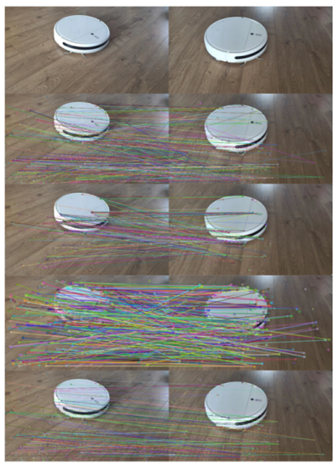
In order to verify the effectiveness of the method, SIFT, ORB, Super Point and the method proposed in the paper were used to extract and match the feature points of two images with adjacent angles. As shown in Figure 4, the two images at the top in the first row are the original input images. The second row is the SIFT operation result, the third row is the ORB operation result, the fourth row is the Super Point operation result, and the fifth row is the operation result of the proposed method. The results data are shown in Table 1. It can be seen that the numbers of matching feature points extracted by SIFT, ORB and the proposed method are smaller than the Super Point algorithm. The results by Sift, ORB and Super Point were doped with a large number of wrong matching results, while the matching accuracy of the proposed method is higher. The locations of planes in the AR scene can be determined based on the sparse point cloud, which has a low requirement for the number of feature points, but high requirement for the accuracy of feature points. Therefore, the method proposed in this paper is better than the other three methods.
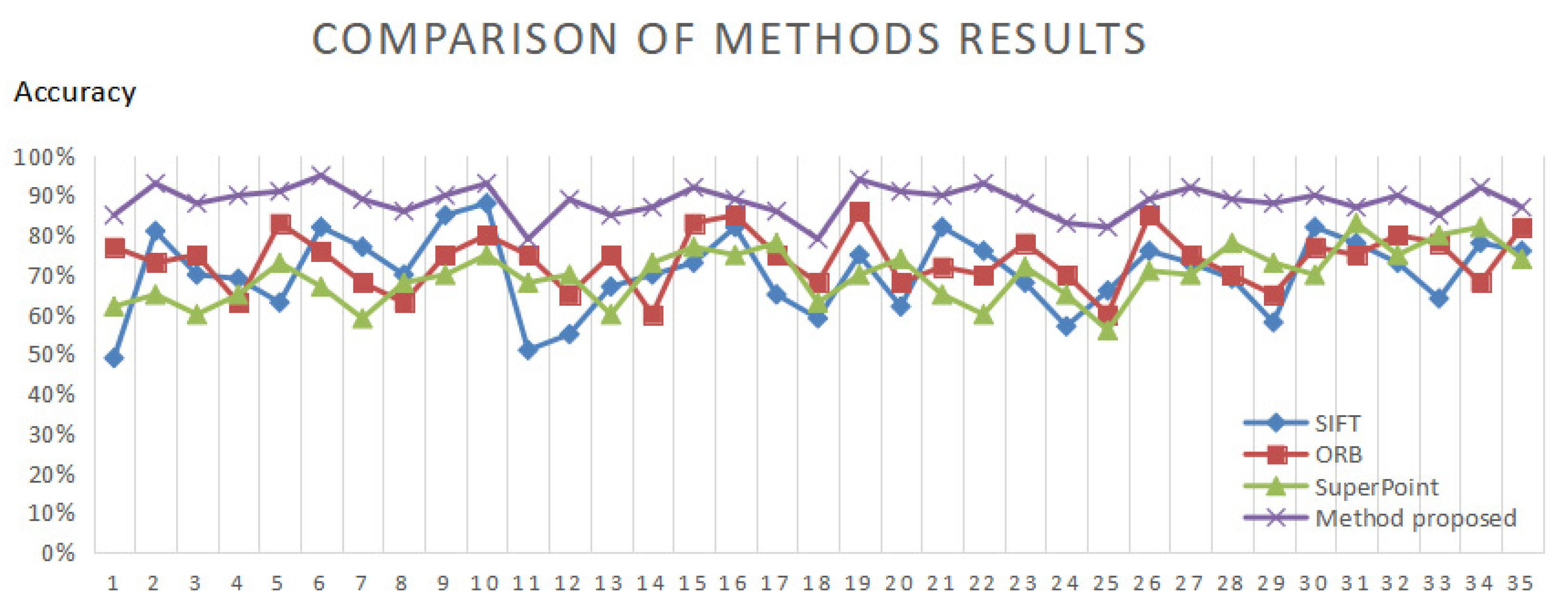
The accuracy of feature points detection and matching results by SIFT, ORB, Super Point and our algorithm for 35 pairs of images are shown in Figure 5. It shows that our method has a higher level of accuracy than the other three algorithms.

3.2. Planes Recognition

Based on the effective feature point pi detected by optimized SIFT, the coordinate of the spatial point P corresponding to the feature point was calculated. After the recursive calculation of 35 photos, a sparse point cloud composed of feature points of the scene can be obtained, as shown in Figure 6.
It can be seen that the sparse point cloud distribution of the scene demonstrates the three-dimensional structural characteristics of the scene. Although it cannot completely show the three-dimensional information of the scene, it can represent the basic structure of the scene, which can be used as an effective support for the augmented reality scene.
We tried to recognize planes by using the classic RANSAC algorithm. As shown in Figure 7, only the floor of the scene could be detected successfully by the RANSAC, while the upper plane was undetected. This is because there were 9963 points in the feature point set of the whole scene, including 9503 points on the lower surface. Due to the unobvious texture, there were only 359 feature points on the upper plane, which were mainly concentrated on the edge, so they were discarded by the classic RANSAC in the detection process.
In order to quickly recognize all possible planes from the point cloud, a plane recognition method has been designed in this paper. The steps are as follows:
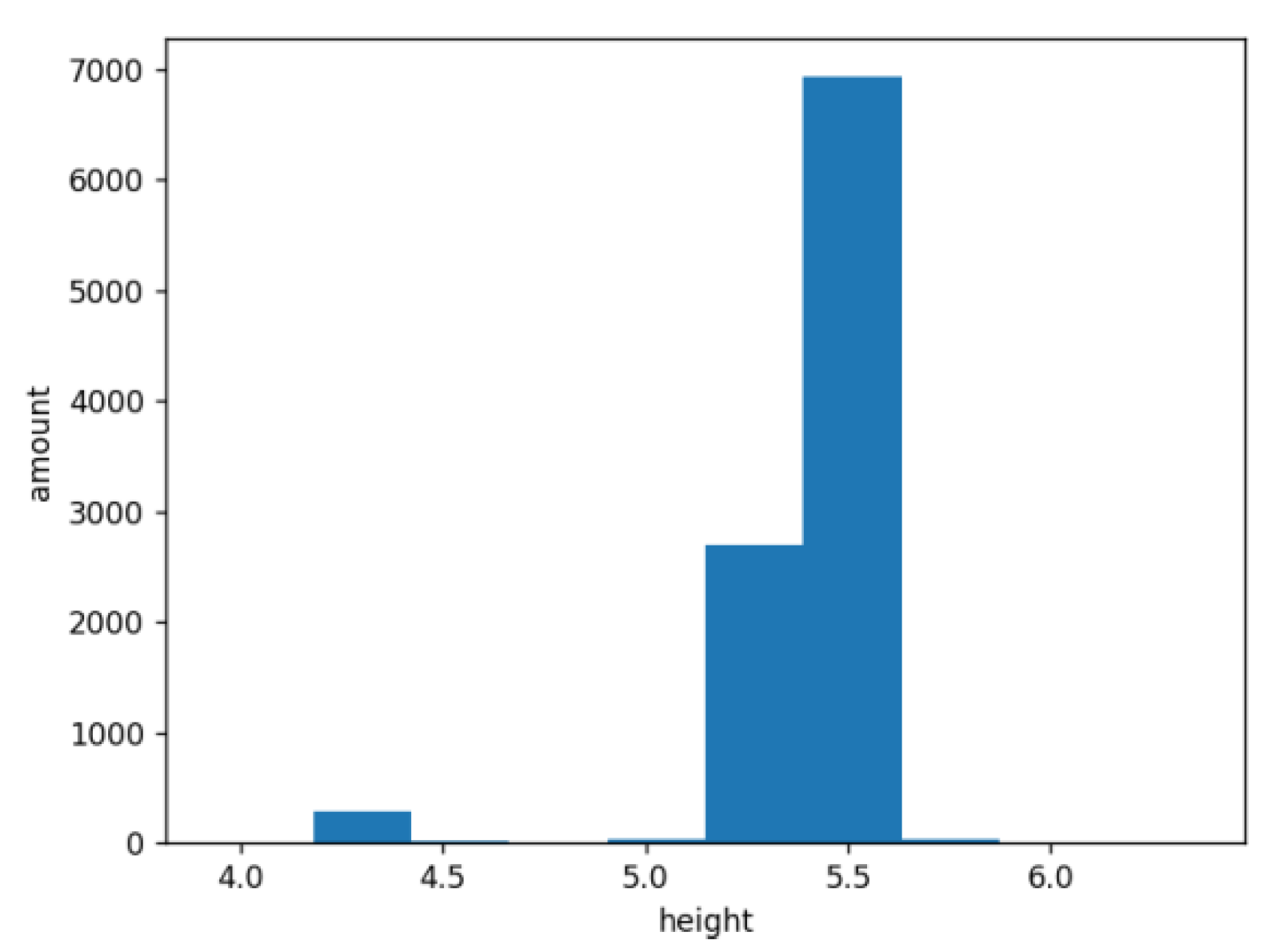
  • Make statistics and analysis on the height data of the point cloud of the scene. There should be a plane at the height where many points are concentrated. Figure 8 shows the number of points at a certain height. It is shown that most point clouds are concentrated in two height ranges, so it is inferred that there are two planes in the scene. The small point set corresponds to the upper plane of the sweeper, and the large point set corresponds to the ground.
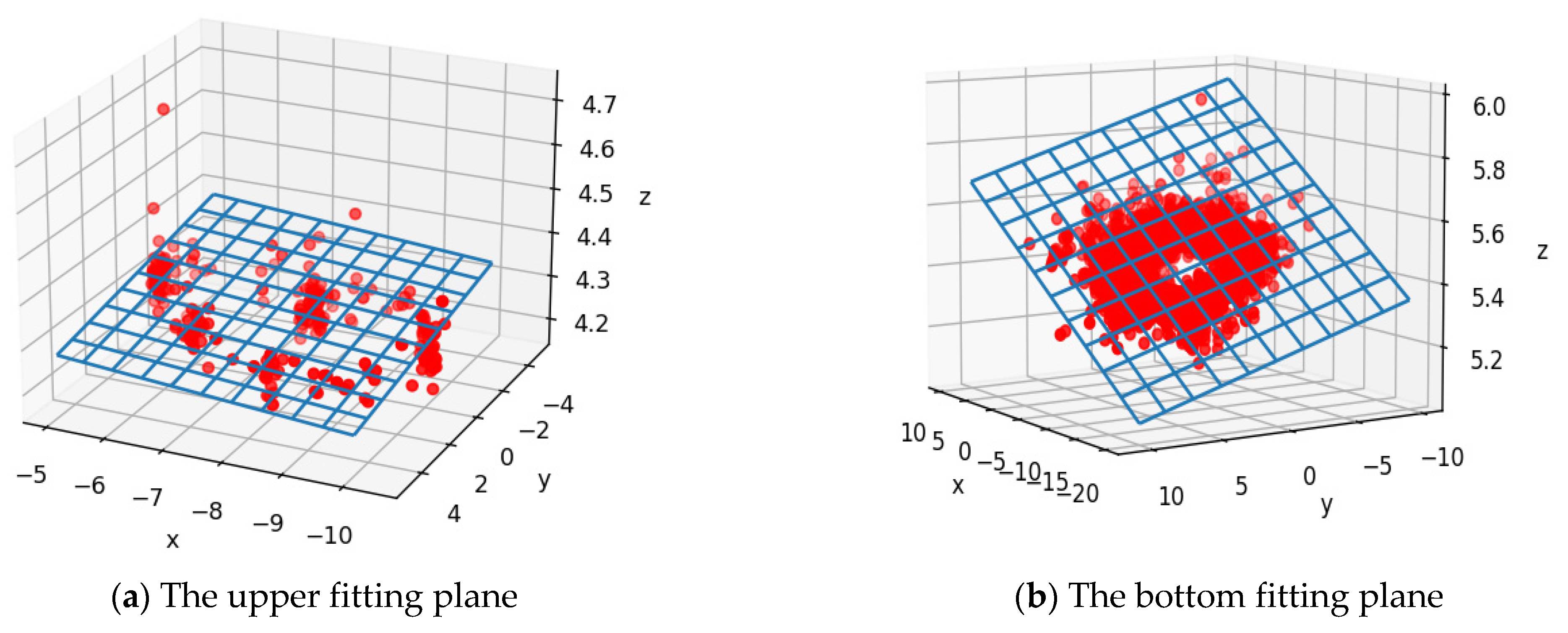
  • The points in the two height ranges are extracted to form two point sets. For each point set, the RANSAC algorithm is used to fit a plane. The process can be executed in parallel. The fitting plane effect is shown in Figure 9. Figure 9a shows the fitting effect of the small point set and Figure 9b shows the fitting effect of the large point set.
  • After fitting the plane equation, the size of the upper plane of the sweeper in the scene can be determined through the coordinate range of small point set.
In order to verify the effect of the optimized algorithm, comparison experiment was performed on a Windows 10 64 system, with i7-11800H CPU and NVIDIA GeForce RTX 3050 Laptop GPU.
The efficiency of an algorithm describes the time used of a certain mission. The efficiency improvement EI is defined as below:
E I = T r T p T r × 100 %
where T r is the time cost to recognize planes by RANSAC, and T p is the time cost by the proposed method.
The operational results of the classical RANSAC method and the method proposed in this paper are shown in Table 2.
It can be seen that the proposed method in this paper could correctly identify two planes in the scene, and the recognition rate is 100%, while the classical RANSAC could only recognize one plane. Through parallel execution, the proposed method reduced a lot of the operation time and improved the execution efficiency by 14.5%.

4. Effect Combined with ARCore

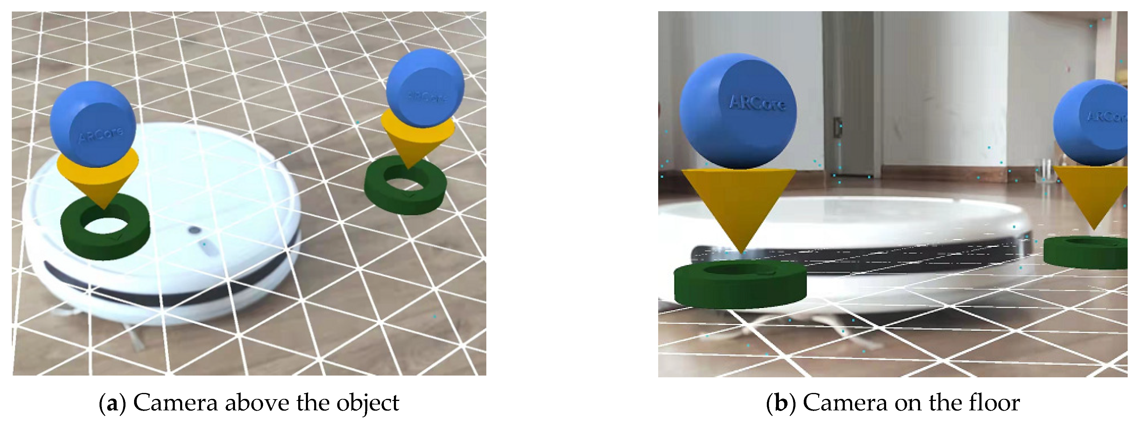
Figure 10a,b shows the ARCore operation effect based on a scene where a sweeper is placed on the floor. In the AR scene, two virtual objects were placed on the ground and on the sweeper, respectively. Figure 10a shows the image of the scene when the camera is upon the object, and Figure 10b shows the scene image when the mobile phone was placed on the floor. It can be seen in Figure 10b that the virtual object on the sweeper was not placed on the sweeper, but sunk to the ground, which caused a phenomenon of virtual object suspension in the senses.
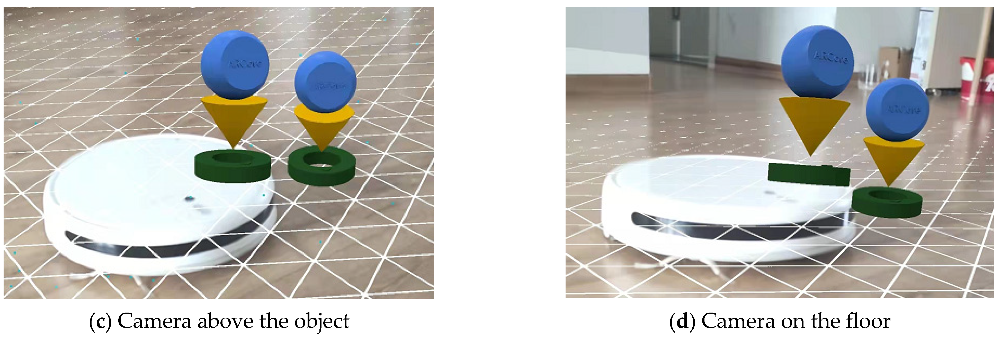
After adding supported information to the augmented reality scene, the operation effect of the augmented reality scene is shown in Figure 10c,d. When clicking on the upper surface of the sweeper, the embedded invisible virtual plane generates response information, and the virtual object is placed on the virtual plane on the upper surface of the sweeper, which results in the visual effect where the virtual object is placed on the sweeper, as shown in Figure 10c. When the shooting angle of the camera changes, as shown in Figure 10d, the view of the virtual object on the virtual plane also changes but does not sink to the ground. Obviously, this is much closer to the real scene. The method proposed in the paper corrects the misjudged plane problem in ARCore.

5. Conclusions

With the help of the series of images of a scene taken by a monocular camera, a 3D sparse point cloud of the scene was constructed, and the plane’s position and size in the 3D scene was estimated. The experimental results show that the augmented reality scene information enhancement method proposed in this paper is effective at solving the problem where with ARCore, it is easy to miss the detection of small planes with unobvious texture, and helps to place the virtual object on the undetected plane to improve the integration effect between the virtual object and the real scene. However, at present, this method requires a long calculation time, and needs to complete a series of image acquisitions and point cloud constructions of the scene in advance. Our next study will try to build 3D scene structures in real time in an augmented reality scene.

Author Contributions

Conceptualization, B.L.; methodology, X.W.; software, Q.G.; validation, B.L., X.W. and Q.G.; formal analysis, Z.S.; investigation, B.L.; resources, X.W.; data curation, S.L.; writing—original draft preparation, X.W.; writing—review and editing, B.L.; visualization, C.Z.; supervision, B.L.; project administration, B.L.; funding acquisition, B.L. All authors have read and agreed to the published version of the manuscript.

Funding

This research was funded by the Liaoning Applied Basic Research Plan (2022JH2/101300251), Liaoning Education Department Scientific Research Project (LJKZ1101), Liaoning Natural Science Foundation Project (2019-MS-238), Shenyang Innovative Talent Support Project (RC180015), Liaoning Province Doctoral Program (2021-BS-197), Liaoning Science Public Welfare Research Fund (2022JH4/10100056).

Data Availability Statement

Data is contained within the article.

Conflicts of Interest

The authors declare no conflict of interest.

References

  1. Caudell, T.P.; Mizell, D.W. Augmented reality: An application of heads-up display technology to manual manufacturing processes. In Proceedings of the 25th Hawaii International Conference on System Sciences, Kauai, HI, USA, 7–10 January 1992; IEEE Computer Society Press: Los Alamitos, CA, USA, 1992; pp. 659–669. [Google Scholar]
  2. Bi, Y.; Zhao, Z. Application of VR Virtual Reality in Navigation Teaching. J. Phys. Conf. Ser. 2020, 1648, 032156. [Google Scholar] [CrossRef]
  3. Morimoto, T.; Kobayashi, T.; Hirata, H.; Otani, K.; Sugimoto, M.; Tsukamoto, M.; Yoshihara, T.; Ueno, M.; Mawatari, M. XR (Extended Reality: Virtual Reality, Augmented Reality, Mixed Reality) Technology in Spine Medicine: Status Quo and Quo Vadis. J. Clin. Med. 2022, 11, 470. [Google Scholar] [CrossRef] [PubMed]
  4. Chiang, F.K.; Shang, X.; Qiao, L. Augmented reality in vocational training: A systematic review of research and applications. Comput. Hum. Behav. 2022, 129, 107125. [Google Scholar]
  5. Sung, E.; Han, D.I.D.; Choi, Y.K. Augmented reality advertising via a mobile app. Psychol. Mark. 2022, 39, 543–558. [Google Scholar] [CrossRef]
  6. Jiang, S.; Moyle, B.; Yung, R.; Tao, L.; Scott, N. Augmented reality and the enhancement of memorable tourism experiences at heritage sites. Curr. Issues Tour. 2022, in press. [Google Scholar] [CrossRef]
  7. Newcombe, R.A.; Izadi, S.; Hilliges, O.; Molyneaux, D.; Kim, D.; Davison, A.J.; Kohi, P.; Shotton, J.; Hodges, S.; Fitzgibbon, A. Kinect Fusion: Real-Time Dense Surface Mapping and Tracking. In Proceedings of the 10th IEEE International Symposium on Mixed and Augmented Reality, Basel, Switzerland, 26–29 October 2011; pp. 127–136. [Google Scholar]
  8. Roth, H.; Vona, M. Moving Volume Kinect Fusion. In Proceedings of the British Machine Vision Conference, Surrey, UK, 3–7 September 2012; pp. 1–11. [Google Scholar]
  9. Whelan, T.; Kaess, M.; Johannsson, H.; Fallon, M.; Leonard, J.J.; McDonald, J. Real-time large-scale dense RGB-D SLAM with volumetric fusion. Int. J. Robot. Res. 2014, 34, 598–626. [Google Scholar]
  10. Fioraio, N.; Taylor, J.; Fitzgibbon, A.; Di Stefano, L.; Izadi, S. Large-scale and drift-free surface reconstruction using online subvolume registration. In Proceedings of the IEEE Conference on Computer Vision and Pattern Recognition, Boston, MA, USA, 7–12 June 2015; pp. 4475–4483. [Google Scholar]
  11. Faugeras, O.; Robert, L.; Laveau, S.; Csurka, G.; Zeller, C.; Gauclin, C.; Zoghlami, I. 3-D Reconstruction of Urban Scenes from Image Sequences. Comput. Vis. Image Underst. 1998, 69, 292–309. [Google Scholar] [CrossRef] [Green Version]
  12. Debevec, P.E. Modeling and rendering architecture from photographs: A hybrid geometry and image based approach. In Proceedings of the Conference on Computer Graphics & Interactive Techniques, Berkeley, CA, USA, 4–9 August 1996; pp. 11–20. [Google Scholar]
  13. Snavely, N.; Seitz, S.; Szeliski, R. Photo tourism: Exploring photo collections in 3D. In ACM Transactions on Graphics (TOG); ACM: New York, NY, USA, 2006; Volume 25, pp. 835–846. [Google Scholar]
  14. Goesele, M.; Snavely, N.; Curless, B.; Hoppe, H.; Seitz, S.M. Multi-View Stereo for Community Photo Collections. In Proceedings of the 11th International Conference on Computer Vision, Rio de Janeiro, Brazil, 14–21 October 2017; IEEE: Piscataway, NJ, USA, 2007; pp. 1–8. [Google Scholar]
  15. Furukawa, Y.; Ponce, J. Accurate, Dense, and Robust Multi-View Stereopsis. In Proceedings of the 2007 IEEE Computer Society Conference on Computer Vision and Pattern Recognition (CVPR 2007), Minneapolis, MN, USA, 17–22 June 2022; pp. 18–23. [Google Scholar]
  16. Snvaley, N. Bundler Structure from Motion (SfM) for Unordered Images. 2007. Available online: http://www.cs.cornell.edu/~snavely/bundler/ (accessed on 4 November 2022).
  17. Bradley, D.; Boubekeur, T.; Heidrich, W. Accurate multi-view reconstruction using robust binocular stereo and surface meshing. In Proceedings of the IEEE Conference on Computer Vision & Pattern Recognition, Anchorage, AK, USA, 23–28 June 2008; pp. 1–8. [Google Scholar]
  18. Furukawa, Y.; Curless, B.; Seitz, S.M.; Szeliski, R. Reconstructing Building Interiors from Images. In Proceedings of the 2009 IEEE 12th International Conference on Computer Vision, Kyoto, Japan, 29 September–2 October 2009; pp. 80–87. [Google Scholar]
  19. Liu, Y.; Xun, C.; Dai, Q.; Xu, W. Continuous depth estimation for multi-view stereo. In Proceedings of the IEEE Conference on Computer Vision & Pattern Recognition, Miami, FL, USA, 20–25 June 2009; pp. 2121–2128. [Google Scholar]
  20. Li, J.; Li, E.; Chen, Y.; Xu, L.; Zhang, Y. Bundled Depth-Map Merging for Multi-View Stereo. In Proceedings of the IEEE Conference on Computer Vision and Pattern Recognition (CVPR 2010), San Francisco, CA, USA, 13–18 June 2010; pp. 2769–2776. [Google Scholar]
  21. Hernandez, E.; Vogiatzis, G.; Cipolla, R. Multiview Photometric Stereo. IEEE Trans. Pattern Anal. Mach. Intell. 2008, 30, 548–554. [Google Scholar]
  22. Vogiatzis, G.; Esteban, C.H.; Torr, P.; Cipolla, R. Multiview Stereo via Volumetric Graph-Cuts and Occlusion Robust Photo-Consistency. IEEE Trans. Pattern Anal. Mach. Intell. 2008, 29, 2241–2246. [Google Scholar] [CrossRef] [PubMed] [Green Version]
  23. Bay, H.; Tuytelaars, T.; Van Gool, L. Surf: Speeded up robust features. In Proceedings of the European Conference on Computer Vision, Graz, Austria, 7–13 May 2006; Springer: Berlin/Heidelberg, Germany, 2006; pp. 404–417. [Google Scholar]
  24. Mandikal, P.; Radhakrishnan, V.B. Dense 3D Point Cloud Reconstruction Using a Deep Pyramid Network. In Proceedings of the 2019 IEEE Winter Conference on Applications of Computer Vision (WACV), Waikoloa, HI, USA, 7–11 January 2019. [Google Scholar]
  25. Lowe, D.G. Distinctive image features from scale invariant keypoints. Int. J. Comput. Vis. 2004, 60, 91–110. [Google Scholar] [CrossRef]
  26. Rublee, E.; Rabaud, V.; Konolige, K.; Bradski, G. Orb: An efficient alternative to sift or surf. In Proceedings of the IEEE 2011 International Conference on Computer Vision, Barcelona, Spain, 6–13 November 2011; pp. 2564–2571. [Google Scholar]
  27. Leutenegger, S.; Chli, M.; Siegwart, R.Y. Brisk: Binary robust invariant scalable keypoints. In Proceedings of the IEEE 2011 International Conference on Computer Vision, Barcelona, Spain, 6–13 November 2011; pp. 2548–2555. [Google Scholar]
  28. DeTone, D.; Malisiewicz, T.; Rabinovich, A. Superpoint: Self-supervised interest point detection and description. In Proceedings of the IEEE Conference on Computer Vision and Pattern Recognition Workshops, Salt Lake City, UT, USA, 18–22 June 2018; pp. 224–236. [Google Scholar]
  29. Deshpande, B.; Hanamsheth, S.; Lu, Y.; Lu, G. Matching as Color Images: Thermal Image Local Feature Detection and Description. In Proceedings of the ICASSP 2021-2021 IEEE International Conference on Acoustics, Speech and Signal Processing (ICASSP), Toronto, ON, Canada, 6–1 June 2021; pp. 1905–1909. [Google Scholar]
  30. Xie, Y.; Wang, Q.; Chang, Y.; Zhang, X. Fast Target Recognition Based on Improved ORB Feature. Appl. Sci. 2022, 12, 786. [Google Scholar] [CrossRef]
  31. Wu, J.; Wang, Y.; Xue, T.; Sun, X.; Freeman, B.; Tenenbaum, J. Marrnet: 3D shape reconstruction via 2.5 d sketches. In Proceedings of the 31st Conference on Neural Information Processing Systems (NIPS 2017), Long Beach, CA, USA, 4–9 December 2017; pp. 540–550. [Google Scholar]
  32. Yu, Y.; Guan, H.; Li, D.; Jin, S.; Chen, T.; Wang, C.; Li, J. 3-D feature matching for point cloud object extraction. IEEE Geosci. Remote Sens. Lett. 2019, 17, 322–326. [Google Scholar]
  33. Dewi, F.; Umar, R.; Riadi, I. Classification Based on Machine Learning Methods for Identification of Image Matching Achievements. J. Rekayasa Sist. Teknol. Inf. 2022, 6, 198–206. [Google Scholar]
  34. Ma, H.; Yin, D.Y.; Liu, J.B.; Chen, R.Z. 3D convolutional auto-encoder based multi-scale feature extraction for point cloud registration. Opt. Laser Technol. 2022, 149, 107860. [Google Scholar] [CrossRef]
  35. Seibt, S.; Lipinski, B.V.R.; Latoschik, M.E. Dense Feature Matching Based on Homographic Decomposition. IEEE Access 2022, 10, 21236–21249. [Google Scholar]
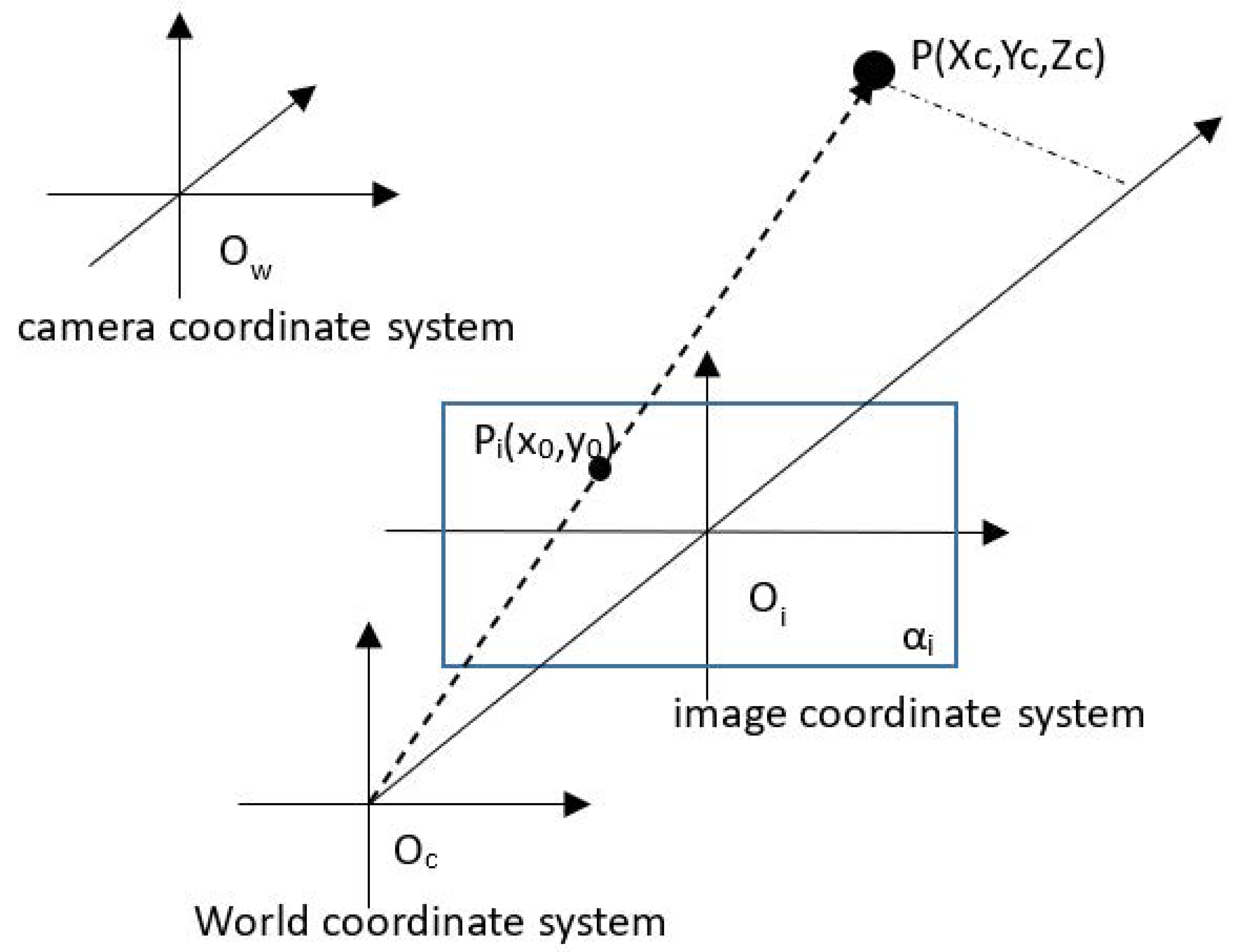
Figure 1. Pinhole imaging model.
Electronics 11 04123 g001
Figure 2. Feature points extraction and matching result of classic SIFT.
Electronics 11 04123 g002
Figure 3. Feature points extraction and matching result of the proposed method.
Electronics 11 04123 g003
Figure 4. Feature-matching comparisons: Input images (top), SIFT feature-matching (second row), ORB feature-matching (third row), Super Point matching (fourth row) and finally, the proposed method matching (bottom).
Electronics 11 04123 g004
Figure 5. Accuracy of feature points detection and matching results.
Electronics 11 04123 g005
Figure 6. The sparse point cloud of the scene. (a) is the flat view of the pont cloud. (b) is the top view of the point cloud.
Electronics 11 04123 g006
Figure 7. Plane recognition result by RANSAC.
Electronics 11 04123 g007
Figure 8. The height data of the point cloud.
Electronics 11 04123 g008
Figure 9. (a) is the upper plane fitting results. (b) is the bottom plane fitting result.
Electronics 11 04123 g009
Figure 10. Image (a,b) are results of ARCore without the proposed method; image (c,d) are results of ARCore with the proposed method.
Electronics 11 04123 g010aElectronics 11 04123 g010b
Table 1. Comparison of experimental results for Figure 4.
AlgorithmFeature Points (Left)Feature Points (Right)MatchedAccuracy
SIFT51337718375.41%
ORB45546825968.34%
Super Point2023147040859.31%
Proposed Method 51337712389.43%
Table 2. Comparison of plane recognition results.
Recognized PlanesAccuracyTime Cost (s)Efficiency Improvement
Classical RANSAC150%0.1930
Method Proposed2100%Upper plane0.01214.5%
Bottom plane0.165
Publisher’s Note: MDPI stays neutral with regard to jurisdictional claims in published maps and institutional affiliations.