Article

PDDQN-HHVBF Routing Protocol Based on Empirical Priority DDQN to Improve HHVBF

1
School of Computer and Electronics Information, Guangxi University, Nanning 530004, China
2
Guangxi Key Laboratory of Multimedia Communications Network Technology, Nanning 530004, China
3
School of Information and Statistics, Guangxi University of Finance and Economics, Nanning 530003, China
*
Author to whom correspondence should be addressed.
Electronics 2022, 11(23), 4031; https://doi.org/10.3390/electronics11234031
Submission received: 21 October 2022 / Revised: 6 November 2022 / Accepted: 1 December 2022 / Published: 5 December 2022

Abstract

:
Reinforcement learning (RL) has been successfully applied to underwater routing protocols due to its powerful ability of distributed decision making. However, the traditional RL has slow convergence speed and low learning efficiency in underwater. Meanwhile, too many studies focus on using RL to find low hop paths rather than short distance paths in underwater routing, while the long distance of ocean communication is the significant reason for the packets collision and energy loss in underwater. Based on the above problems, this paper proposes the PDDQN-HHVBF (Empirical Priority DDQN to Improve Hop-by-Hop Vector-Based Forwarding) protocol for M-UWSNs (Mobile source node Underwater Wireless Sensor Networks), in which AUV (Autonomous Underwater Vehicle) is used as source node to collect data and transmit data hop-by-hop to Sink node through underwater nodes. The proposed protocol is adopt to find the optimal relay nodes in pipeline referred HHVBF protocol by requesting the max Q value according to three states of the residual energy of nodes, the number of candidate relay nodes and the geographical location information of all candidate relay nodes in time. This because PDDQN-HHVBF avoids the strong correlation between data samples, and its playback samples will not be too concentrated or lead to over fitting. It can converge rapidly in underwater environment. In addition, the requesting Q value mechanism related to the geographical location information can find the optimal relay node with short distance propagation in large-scale networks, which will reduce the number of packets collision, and then saving energy and improving network lifetime. In addtion, the in-time requesting for Q value can cope with the nodes drift affected by ocean current movement. In addition, the Q value related to the residual energy of nodes and the number of candidate relay nodes will effectively load balancing nodes, prolong network lifetime and avoid routing holes. Finally, the “Store-Carry-Forward” mechanism proposed for AUV, this mechanism store and carry packets when facing routing holes until find the optimal relay node for forwarding, which will improve PDR and save energy of AUV significantly. The simulation results show that, the proposed PDDQN-HHVBF protocol converges about 30% faster than DQELR. Although its delay is higher than DQELR and ROEVA for requesting Q value. It outperforms VBF, HHVBF, DQELR, and ROEVA in terms of energy efficency, PDR, and lifetime, which are analyzed by varying speed of nodes from 0 m/s to 3 m/s with 1000 nodes and varying number of nodes from 500 to 3000 with speed in 1 m/s.

1. Introduction

1.1. Background

Under the circumstances that terrestrial resources are over-exploited and it is still difficult to meet human needs, the oil resources, natural gas resources, tidal energy resources, wind energy resources, and fishery resources contained in the ocean can largely meet the needs of human lifetime and economic development. Underwater Wireless Sensor Networks (UWSNs) have strong capabilities in underwater resource exploration, marine geographic and meteorological data collection, earthquake/tsunami disaster prevention, water pollution monitoring, and national defense security. It has received increasing attention in the field of marine science and technology. In addtion, it has become an indispensable tool for human exploration of the marine world [1,2,3,4]. In addition, sixth generation (6G) systems enable users to share information globally across a broad spectral range, and in full application with extremely low latency and high data rates. In recent years, the demand for mobile communication Stronger capabilities, wider scope, and growing in the industrial field [5,6,7,8]. Similarly, the application scenarios of 6G in underwater are also extremely wide, and it is also a direction that researchers need to pay attention to in the future.
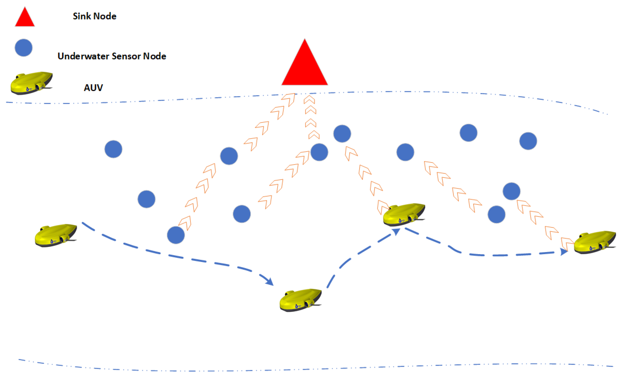
UWSNs is composed of sensor nodes deployed underwater, the Sink node on the sea surface, and autonomous underwater vehicle (AUV), which use acoustic waves to transmit information to each other [9]. Among them, the sensor node can be used as a collection node to collect ocean data and forward it to the relay node, or it can be used as a relay node to receive the data collected by the collection node and then forward it to the Sink node hop by hop. AUV can be regarded as a mobile underwater wireless sensor node. It is an ideal mobile measurement instrument platform due to its advantages of large activity range, no umbilical cord entanglement, no need for a huge surface support system, and low operation and maintenance costs. It can be used in marine exploration, underwater search and rescue, underwater special operations, etc. [9]. The underwater mobile wireless sensor network containing AUV expands the monitoring range of traditional UWSNs to the environment, and improves the ability of UWSNs to track and detect marine physical phenomena. During the development of UWSNs routing protocol, because the underwater acoustic channel has the variable transmission characteristics of “time-space-frequency”, that is, the underwater acoustic channel has a long propagation time, unstable network topology, and low network bandwidth [9]. It is impossible to directly apply the Terrestrial Wireless Sensor Networks (TWSNs) routing protocol to UWSNs, and it is necessary to study the routing protocol suitable for underwater acoustic channels [10,11]. Especially for the Mobile source node Underwater Wireless Sensor Networks (M-UWSNs) that uses AUV as the source node to collect data and transmit the data to the Sink node hop by hop. The “time-space-frequency” transmission characteristics of the acoustic channel make the data packet delivery ratio is low, the energy consumption is large, and the network lifetime is short. The schematic diagram of M-UWSNs is shown in Figure 1.

1.2. Motivation and Contributions

Mobile source node Underwater Wireless Sensor Networks (M-UWSNs) is a network structure in which Autonomous Underwater Vehicle (AUV) is used as source node to collect data and transmit data packets hop-by-hop to Sink node through underwater nodes. Due to long propagation in underwater, there are high packet collision rate and unreliable transmission, it will lead to low packet delivery ratio (PDR), high energy consumption, short network lifetime in M-UWSNs. In addition, due to the small number of nodes and the distribution is scattered in the sparse network, M-UWSNs faces the problem of routing holes, which leads to low PDR and extra energy wasting. Specially for AUV with routing holes, energy limited AUV will waste a lot of energy in the data forwarding process, resulting in not enough energy for AUV to complete tasks.
In view of the above problems, this paper proposes an improved HHVBF protocol based on the empirical priority DDQN algorithm, namely, the PDDQN-HHVBF (Empirical Priority DDQN to Improve Hop-by-Hop Vector-Based Forwarding) protocol. The protocol use Empirical Priority DDQN to find the optimal relay node in pipeline referred HHVBF (Hop-by-Hop Vector-Based Forwarding) protocol by requesting the Q value considering the number of candidate relay nodes, the residual energy of nodes, and the geographical location information of nodes from candidate relay nodes in time. The proposed protocol aims to the high PDR and the long network lifetime in the large-scale network, and effectively avoids the occurrence of routing holes caused by ocean current movement in sparse M-UWSNs. Finally, the “Store-Carry-Forward” mechanism proposed for AUV, this mechanism store and carry packets when facing routing holes, which will improve PDR and save energy of AUV significantly. The main contributions of this paper are as follows:
(1).
We design the PDDQN-HHVBF routing protocol to find the optimal relay node to forward in M-UWSNs. The DDQN algorithm based on empirical priority has the advantages of fast convergence speed, fast learning speed and stable learning process. It can quickly converge in M-UWSNs and obtain the formula for finding the optimal relay node function.
(2).
PDDQN-HHVBF enables the pre-forwarding nodes find the optimal relay nodes with the max Q value to propagate packets considering the the geographical location information of nodes in time, which makes the high PDR and low energy consumed due to the shorter distance to propagate packets.
(3).
PDDQN-HHVBF protocol enables the pre-forwarding nodes request the Q value considering the number of candidate relay nodes. This because the more candidate relay nodes there are, the less likely the nodes are to suffer from routing holes. Thus, the method can effectively avoids the occurrence of routing holes caused by ocean current movement in sparse M-UWSNs.
(4).
PDDQN-HHVBF enables the pre-forwarding node to request the Q value considering the residual energy from the candidate relay nodes. This method can balance the load of the candidate relay node, thereby extending the network lifetime.
(5).
We proposes a “Store-Carry-Forward” mechanism. This mechanism store and carry packets when facing routing holes until a suitable relay node is found for forwarding, which will improve PDR and save energy of AUV significantly.
The remainder of the paper is organized as follows: We introduce some other related work in Section 2. We introduce the concept of reinforcement learning and related algorithms in Section 3. In Section 4, we introduce the specific process of the PDDQN-HHVBF routing protocol. In Section 5, we introduce the setting of simulation parameters used in the simulation and the discussion of the simulation results. Finally, the Section 6 concludes this research and suggests some future works.

2. Related Works

In this part, we mainly review the related routing protocols of UWSNs and analyze the advantages and disadvantages of these protocols.
There are some location-based routing protocols, such as VBF (Vector-Based Forwarding) [12], HHVBF (Hop-by-Hop Vector-Based Forwarding) [13] and AHHVBF (Adaptive Hop-by-Hop Vector-Based Forwarding) [14]. VBF utilizes location information to improve the energy efficiency of dynamic networks. In VBF, data packets are delivered within the range of the routing pipeline, and nodes within this range will be used more frequently than nodes outside this range, which will lead to unbalanced energy consumption and shorten network life. In order to solve the problem of VBF, HHVBF, and AHHVBF are proposed, respectively. The HH-VBF protocol and the AHHVBF protocol also use the idea of routing pipeline. Unlike VBF, both HHVBF, and AHHVBF do not use a fixed pipeline to transmit data, but establish a new pipeline after each data transmission. In this way, compared with VBF, HHVBF, and AHHVBF protocols can still transmit data efficiently in areas with low node density, so they have higher packet delivery ratio, and each node can be used evenly, resulting in longer network lifetime. However, using the two protocol, a large network with a large number of nodes has a high data collision rate and low network lifetime.
There are some depth-based routing protocols. In [15], Yan et al. proposed a depth-based routing (DBR) protocol, which effectively reduces the energy consumption and the number of collisions. The DBR protocol uses a greedy algorithm to delivery data packets from the sender to the receiver according to the depth information. However, if there is no surface receiver near the node, the data packets carried by the node will be discarded. In addition, the data packets can only be bottom-up transmission cannot meet the requirements of surface receivers to transmit data down. Based on the DBR protocol, the fuzzy depth-based routing protocol (FDBR) [16] comprehensively considers hop count, depth and energy information to select forwarding nodes, thereby improving the energy efficiency and end-to-end delay performance of the UWSNs. High latency is also a challenge for underwater acoustic communication due to the slow propagation speed of acoustic signals in UWSNs. B. Diao et al. [17] proposed an EE-DBR protocol that no longer uses the depth threshold used in DBR to narrow down the set of candidate nodes, instead uses ToA (Time of Arrival) technology [18] to remove a fixed area to narrow down the range of the candidate forwarding set. However, when nodes are deployed sparsely, the algorithm cannot effectively solve the routing hole problem. There are other depth-based routing protocols, such as VAPR (Void-Aware Pressure Routing) [19], IVAR (Inherently Void Avoidance Routing) [20], and OVAR (Opportunistic Void Avoidance Routing) [21], etc. These methods make use of hops, distance, forwarding direction and other information to keep packets away from the routing void during forwarding. However, on the premise of guaranteeing data transfer rate, these methods sacrifice more real-time performance, and the end-to-end delay is high. At the same time, the state change of some nodes will also lead to the state change of many other nodes, resulting in higher network overhead.
Although traditional routing protocols have improved network performance, the underwater environment is relatively harsh, and routing protocols must still deal with many constraints [22]. Today, Multi-Agent Reinforcement Learning (MARL) [23] has been successfully applied in multiple domains involving distributed decision making. A fully distributed underwater routing problem can be thought of as a cooperative multi-agent system. In [24], adaptive, energy-efficient, and lifetime-aware routing protocol based on Q-learning (QELAR) uses the method of Q-learning to calculate its own routing decision. QELAR comprehensively considers the energy consumption of sensor nodes and the remaining energy distribution between adjacent nodes when designing the Q-value function, thereby optimizing the total energy consumption and network lifetime. However, the simulation model adopted by QELAR is for fixed nodes, which is not suitable for the situation where the movement of ocean currents causes node drift changes. In order to improve the real-time performance of the algorithm, an underwater multistage routing protocol (MURAO) based on Q-learning is proposed in [25]. MURAO uses clustering to divide sensor nodes into algorithmic node sets for multiple sensors. The nodes in the cluster aggregate the collected data to the cluster head, and the cluster head routes to the sink node through multiple hops. MURAO allows multiple clusters to route data to sink nodes in parallel, improving real-time performance, but increases redundant data in the network and may cause data conflicts. In [3], a DQN-based routing decision protocol DQELR with adaptive energy consumption and delay is proposed, which effectively prolongs the network lifetime of UWSNs. In addtion, the protocol adaptively selects the optimal node as a relay node according to the energy and depth state of the communication phase. However, this protocol uses DQN with a slow convergence speed, and does not consider the routing hole problem in the sparse network state, and is applicable to a single scenario. Ref. [26] proposed a reinforcement-learning based routing congestion avoidance (RCAR) protocol. In order to improve energy efficiency and reduce end-to-end latency, the RCAR makes routing decisions based on congestion and energy. However, they do not consider void holes and cannot guarantee the reliability of transmission. Moreover, Zhou et al. [27] designed a routing protocol for UWSNs, which focus on the characteristics of high energy consumption and high latency. This paper investigates a Q-learning-based localization-free routing protocol (QLFR) to prolong the lifetime as well as reduce the end-to-end delay for underwater sensor networks. However, the protocol does not consider the problem that nodes with large Q values become routing holes due to the influence of move current movement. Chen et al. [28] proposed a Q-learning based multi-hop cooperative routing protocol for UWSNs named QMCR, which can automatically choose nodes with the maximum Q-value as forwarders based on distance information. Aiming to seek optimal routing policies, Q-value is calculated by jointly considering residual energy and depth information of sensor nodes throughout the routing process. In addtion, they define two cost functions (depth-related cost and energy-related cost) for Q-learning, in order to reduce delay and extend the network lifetime. The algorithm considers the overall energy consumption of the system, but does not consider the individual energy consumption of nodes. Therefore, the problem of short network life due to common relay node energy depletion will occur. Aiming at the problem of routing holes, Zhang et al. [1] proposed a routing algorithm RLOR based on Q-learning, which combines the advantages of opportunism routing and reinforcement learning algorithms. The RLOR is a kind of distributed routing approach, which comprehensively considers nodes’ peripheral status to select the appropriate relay nodes. Additionally, a recovery mechanism is employed in RLOR to enable the packets to bypass the void area efficiently and continue to forward, which improves the delivery rate of data in some sparse networks. However, this protocol only has good performance for sparse networks. For large-scale UWSNs, this protocol does not effectively reduce data conflicts. For large-scale UWSNs, this protocol throughput and energy consumption performance are not good. Zhu et al. [29] developed a reinforcement learning-based opportunistic routing protocol to enhance transmission reliability and reduce energy consumption. A reward function was developed based on reinforcement learning to seek optimal routing rules. Before forwarding the data packet, a two-hop availability checking function was defined, which avoids routing holes and identifies the trap nodes. However, this protocol only focus on the static nodes. When nodes move influenced by ocean current movement, it will perform worse.
Although the above methods can reduce the delay, packet loss ratio and energy consumption of UWSNs to a certain extent. However, there are no good research results for M-UWSNs with mobile nodes as source nodes. And too many underwater routing protocols with RL pay attention to find low hop paths rather than short distance paths, while the long distance of ocean communication is the significant reason for the packets collision and energy loss in underwater. Thus, problems of low network lifetime, high energy consumption, and low packet delivery ratio of M-UWSNs have not been better solved. Based on the above problems, this paper proposes the PDDQN-HHVBF protocol, which aims at finding the optimal relay node to maximizing the packet delivery ratio, optimizing energy consumption and prolonging the network lifetime. In addition, when the AUV cannot find a suitable relay node during forwarding, this paper proposes the “Store-Carry-Forward” mechanism. In this way, AUV avoids wasting a lot of energy in searching for relay nodes or sending the same data packet repeatedly.

3. Reinforcement Learning

The PDDQN-HHVBF protocol uses the idea of Reinforcement Learning to find the optimal relay node. In this part, we will mainly introduce the concept of reinforcement learning and related algorithms, such as Q-learning, DQN, and DDQN.
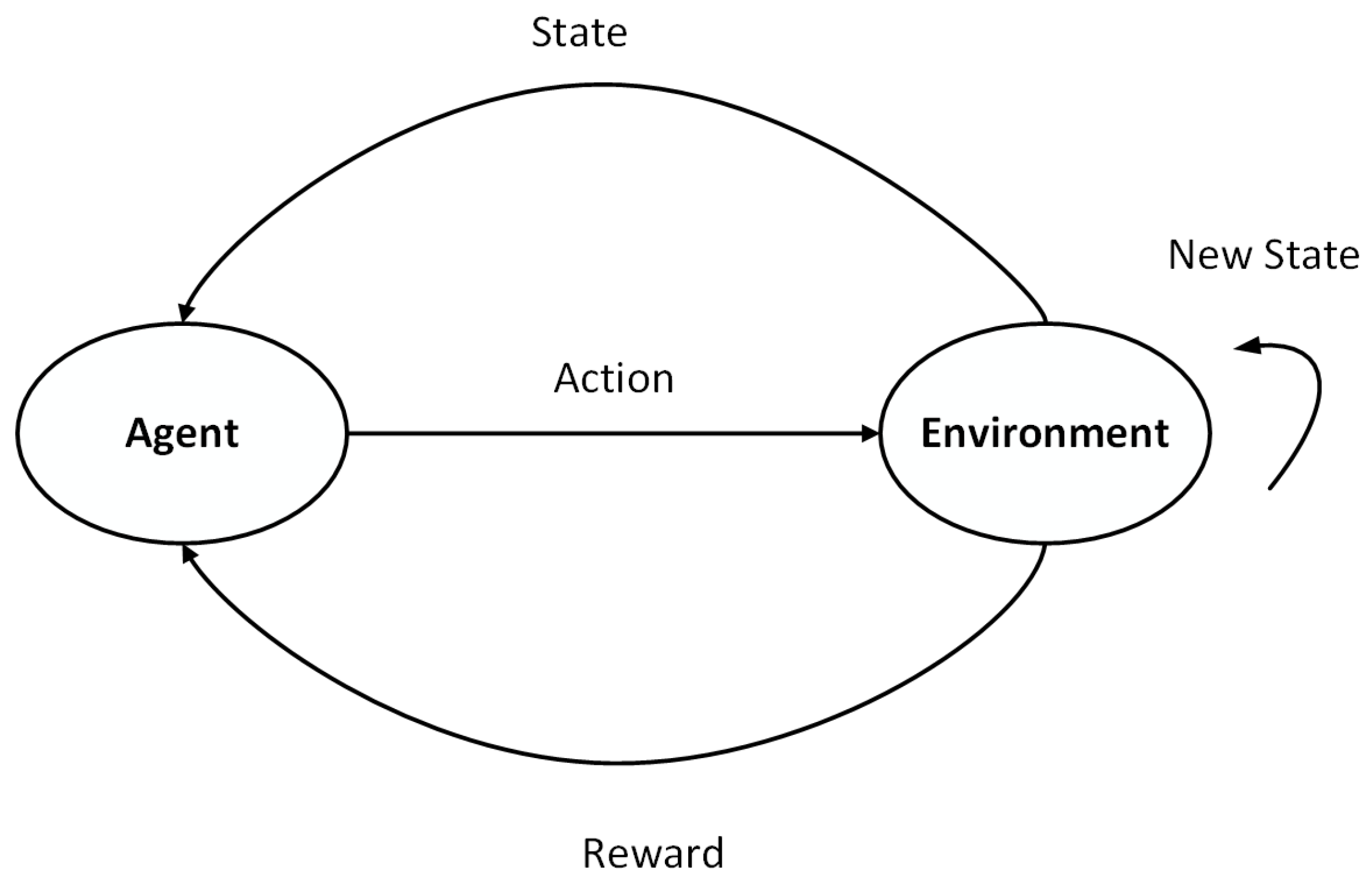
Reinforcement Learning (RL) is one of the paradigms and methodologies of machine learning, which describes and solves the problem that an agent achieves specific goals in the process of interacting with the environment through learning in a way that maximizes returns. Most RL methods are based on estimated value functions, state functions or state–action pairs ( s , a ) . It assesses how well an agent is in a specific state in the environment, or how well it performs a task [3]. Usually the sample of RL is a time series, and the problem of RL is modeled and introduced into the Markov decision process (MDP). MDP is the theoretical basis for the use of RL in this paper. The schematic diagram of MDP is shown in Figure 2.
Q-learning [3] is an important RL algorithm that is widely used in various agent systems. This algorithm has the characteristics of ensuring convergence under certain conditions and has become the most widely used RL algorithm. When using Q-learning, the agent selects a action in the current state of the environment. After the environment receives the action, it will update to a different state, and then the environment will feed back a reward signal to the agent according to the changed state. After the agent receives the reward signal, the agent chooses the next action according to the received reward signal. In general, the state parameters are random, and the action selected by the agent according to the random state is also random. Therefore, a set of data pairs of state and action, together with the rules for changing the state, constitute a Markov decision process. During this process, a sequence of states, actions and rewards ( S , A , R ) is formed. The ( S , A , R ) expansion is shown in Formula (1)
s 0 , a 0 , r 1 , s 1 , a 1 , r 2 , s 2 , , s n 1 , a n 1 , r n , s n
where s 0 is the initial state under environment, s i refers to the state parameters of the agent in the state after the i iterations, a i denotes the action that can only be selected in the s i , r i + 1 is the reward value of the environment feedback after the agent performs a i . At the same time, the Q-learning algorithm is a Markov decision process, that is, the next state s i + 1 in this process only depends on the current environmental state s i and the selected action a i in the current state. MDP will end when the state of the agent is s n , that is, when the agent reaches a certain state set, the MDP ends. The learning goal of the agent using Q-learning is to maximize the cumulative return in the future. Q-learning is to estimate the reward value function according to the environmental state and the behavior taken at different times. Through multiple iterations of learning, the estimated reward value function is close to the real reward value function. At the same time, the agent needs to evaluate each action and expected reward value in each environmental state. The reward value function of the action a i performed by the environmental state s i is Q ( s i , a i ) , and the expected value of Q ( s i , a i ) is shown in the Formula (2) as shown:
Q s i , a i = E r i + 1 + γ r i + 2 + γ 2 r i + 3 + s i , a i = E s r i + 1 + γ Q s , a s i , a i
where r i + 1 refers to the reward and return value obtained by the agent after selecting the action a i from the state s i . The learning goal of Q-learning is to find the action with the maximum reward value, that is, to maximize Q ( s i , a i ) , the Q ( s i , a i ) function conforms to the Bellman formula, and the maximization of Q ( s i , a i ) is expressed as Formula (3):
Q π s i , a i = E r i + γ max a Q π s , a s i , a i
where γ max a Q π s , a is the estimated value representing the selection action of the state s i + 1 , and a represents the action under state s i + 1 that the agent may perform. The Q value in the formula can also be obtained by an iterative method. In this way, the Q value stored in the agent needs to be updated in each iteration process, which will waste a lot of time and space, so this method is not adopted. When doing experimental work, we can only collect partial samples for learning. Therefore, we will use the idea of combining the Temporal Difference algorithm (TD) to calculate and update the Q value. The update method is as shown in Formula (4):
Q π s i , a i = Q π s i , a i + α r i + 1 + γ max a Q π s i + 1 , a Q π s i , a i
where α ( 0 , 1 ] , which is the learning rate of the agent, γ is the loss factor of the reward value, and a is the behavior that the agent may perform in the state s i + 1 . The formula is that the agent chooses the behavior execution that maximizes Q π s i + 1 , a among all possible actions. The agent will use a two-dimensional list to store the environmental state, the action taken and the corresponding reward value. In addtion, it queries the agent’s executable action a i according to the state s i , and obtain the corresponding reward value Q ( s i , a i ) .
The storage method of Q-learning is to store all states and corresponding actions in the agent environment, as well as the resulting reward values, in a two-dimensional form. When the environment is complex, the number of states of the agent will be very large, and there will be many actions that may be taken. At this time, the two-dimensional list of stored state-behavior reward values will be too large and complicated, not only occupying a lot of storage space of the agent, but also It will cause the agent to take too long to query the Q table, so the Q-learning algorithm is only suitable for simple environments, and the efficiency is very low in complex environments. Different from the establishment of Q table in the Q-learning algorithm, which takes up a lot of space, DQN [30] adopts the method of neural network combined with Q-learning, and obtains a function to calculate the Q value by using the parameter ω to train and fit. Not only can it save the storage space of the agent, but also does not need to spend a lot of time to query the Q table. Only in a specific environment state, DQN can output the income value of a specific action, and then the agent only needs to select the maximum income value. The action can be executed. The learning logic of DQN is to train the neural network parameter ω through multiple ( S , A , R ) samples, so that the predicted return value function approximates the real return value function. The key to this approach is training the neural network. Therefore, it is necessary to determine the loss function to train the neural network. DQN uses mean squared error to define the objective function. The loss function is shown in Formula (5):
L ( ω ) = E r + γ max Q s , a ω Q ( s , a ω ) 2
where γ max Q s , a ω is the target value for updating the Q value in DQN, Q ( s , a ω ) is the current value of the Q value predicted in the neural network. Then, we calculate the gradient of the neural network weight parameter ω relative to the loss function, and use Formula (6) to calculate the gradient value of the loss function relative to the parameter ω .
L ( ω ) ω = E r + γ max a Q s , a ω Q ( s , a ω ) Q ( s , a ω ) ω
L ( ω ) ω can be calculated from the network structure. Then, we use the gradient descent method to update the parameter ω until the loss function converges. However, the continuous state has a strong correlation with the action input. The action in one state will generate a reward value, and updating the parameters will affect the actions in other states. So, compared with the Q-learning algorithm, DQN is unstable. This instability can greatly affect the convergence speed of DQN. Reference [31] proposed an experience replay method to solve the DQN instability problem. This method is that when the agent needs to use new data samples to update the parameters, it will also randomly sample the previously learned data to learn again, thereby avoiding the DQN instability problem caused by the correlation between state and action. The specific method is to store the state, action, reward and the next state sequence [ s , a , r , s ] of the agent after each learning into an experience pool sequence D. In addtion, each time the reward function is updated to reuse the training to minimize the objective function, as shown in Equation (7).
L ( ω ) = E s , a , r , s U ( D ) r + γ max Q s , a ω Q ( s , a ω ) 2
where ( s , a , r , s ) U ( D ) denotes that the experience sequence D taken during the experience playback is a uniform random distribution sequence, s indicates the transition from the state s to the next state, and a indicates the action that may be performed in the environment state of s . The above-mentioned experience replays DQN based on uniform distribution can avoid the strong correlation between data samples, which makes the training samples independent and identically distributed, and experience replay also enables reinforcement learning to learn and train in past strategies, makes the learned parameters more stable. However, this method is sensitive to the size of the experience pool. If too much experience is used, the learning time will be too long and the convergence speed will be too slow. In addition, there is a correlation between γ max Q ( s , a ω ) and the expected value of the current state Q ( s , a ω ) Based on the above problems, researchers proposed a method [32], which uses a new neural network to generate the target value and use it as the final policy. The idea of the way is to calculate the target value and the current state estimate separately. In this way, there is no correlation between γ max Q s , a ω and Q ( s , a ω ) . This method is called DDQN (Double Deep Q-Network) algorithm, and the loss function of this algorithm is as Formula (8):
L ( ω ) = E s , a , r , s U ( D ) r + γ max a Q s , a ω Q ( s , a ω ) 2 = E Q target Q ( s , a , ω ) 2
where ω is the weight parameter of the target Q-Network. During the algorithm training, ω will periodically synchronize from the parameter ω of the current Q-Network. The objective value function of DDQN is shown in Formula (9):
Q target D D Q N = r i + 1 i + 1 is end r i + 1 + γ Q s i + 1 , argmax α Q s i + 1 , a , ω , ω i i + 1 is not end
if state i + 1 is the state that ends the task, then Q target D D Q N = r i + 1 . Otherwise Q target D D Q N = r i + 1 + γ Q s i + 1 , argmax α Q s i + 1 , a , ω , ω i . Where Q and Q are the same network structure, the Q network is used to update the parameter selection action a, and the Q network is fixed and used for the target network to calculate the Q value.

4. PDDQN-HHVBF Protocol

In the large-scale networking of M-UWSNs, researchers often set nodes with an appropriate density in the water to meet the mission requirements. However, due to the movement of ocean currents, the nodes drift, and the density of nodes in some areas is low, and the nodes in some areas are too dense. Routing holes may arise if the AUV sends data to a less dense area. In addtion, if data are forwarded to an area with high density, the selected relay node may appear to be the same relay node of multiple nodes, resulting in the problem of high delay caused by data collision or multiple backoffs when sending data at the same time. In addition, the more relay nodes that can be selected, the slower the algorithm converges. In view of the above problems, this paper proposes PDDQN-HHVBF, which combines the HHVBF protocol virtual pipeline method to transmit data in the pipeline with the distance vector as the parameter and the DDQN algorithm based on empirical priority to find relay nodes. The DDQN algorithm based on empirical priority can try to avoid the problem of routing holes, and find the route that can be successfully transmitted to the Sink node. The virtual pipeline makes the data packet propagate to the Sink node with the shortest distance, and the short-distance routing protocol greatly reduces the collision probability of the data packet in large-scale M-UWSNs. In addition, PDDQN-HHVBF will fully consider the energy problem of candidate relay nodes, so that the node energy load is balanced. In addtion, in this way, the M-UWSNs network lifetime is longer. Finally, this paper proposes a “Store-Carry-Forward” mechanism. This mechanism makes AUV not forward data temporarily when it cannot find a suitable relay node, but continue to carry and store the data and continue to collect new data packets according to the track until it finds the suitable relay node. Then, the AUV forwards all stored data at the suitable relay node.
This section will introduce the specific process of the PDDQN-HHVBF routing protocol, from the establishment of the virtual pipeline, the setting of candidate relay nodes, the DDQN algorithm based on empirical priority, the selection of the optimal relay node, and the “Store-Carry-Forward” mechanism of AUV. These five aspects describe in detail the working principle of the PDDQN-HHVBF routing protocol.

4.1. Establishment of the Virtual Pipeline

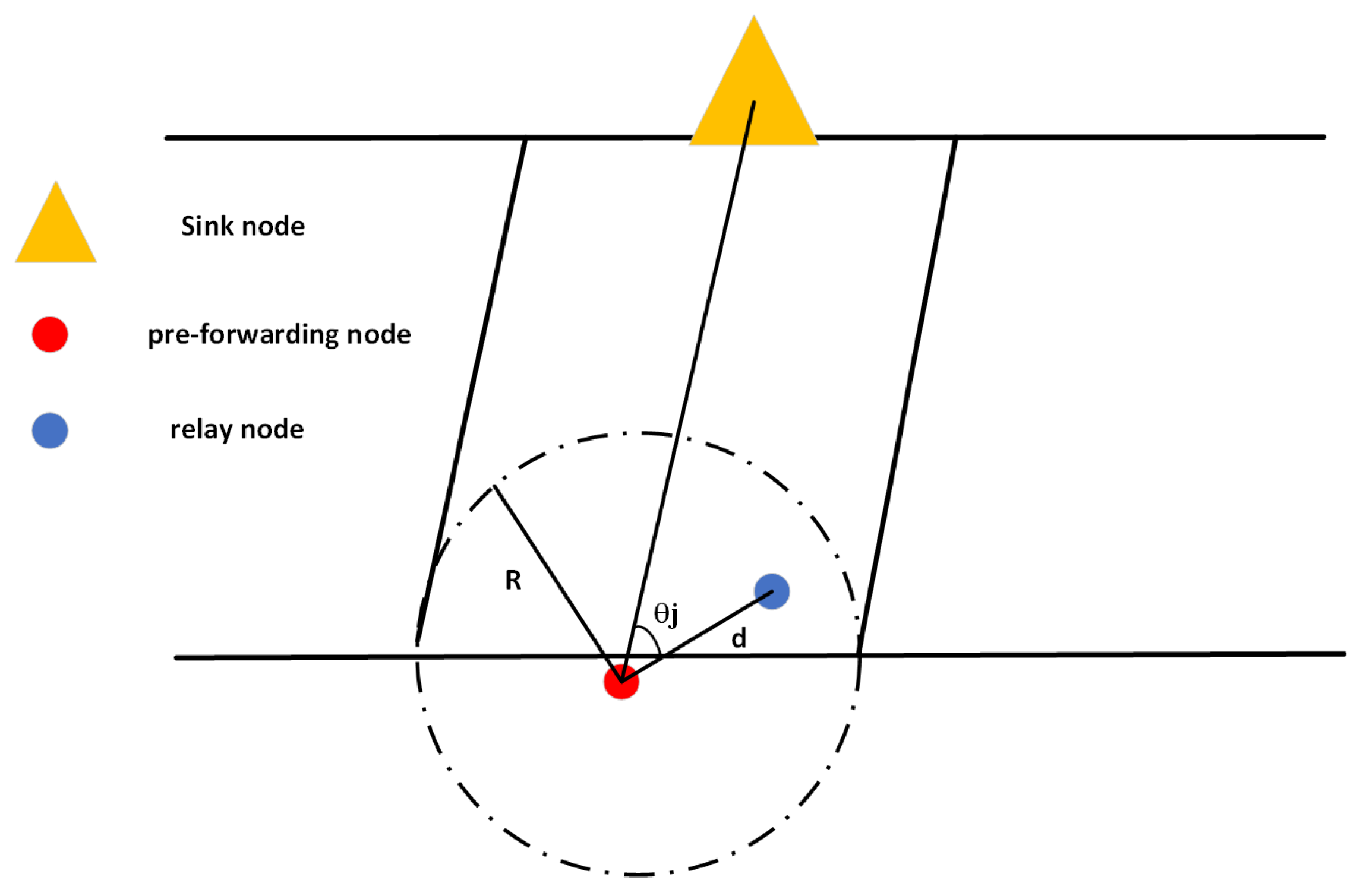
This part mainly introduces the way of establishing the virtual pipeline. Before the AUV and each node in M-UWSNs transmit data, a virtual pipeline is established with the Sink node. The virtual pipeline is established as shown in Figure 3. As Figure 3, the radius of the pipeline is R, and d is the distance that the node deliveries data to the relay node. This paper assumes that the transmission range of AUV and all nodes is the same, and the virtual pipeline radius and transmission range are the same as R. The nodes in the pipeline are the nodes that the sending node can transmit to, that is, the candidate relay nodes.
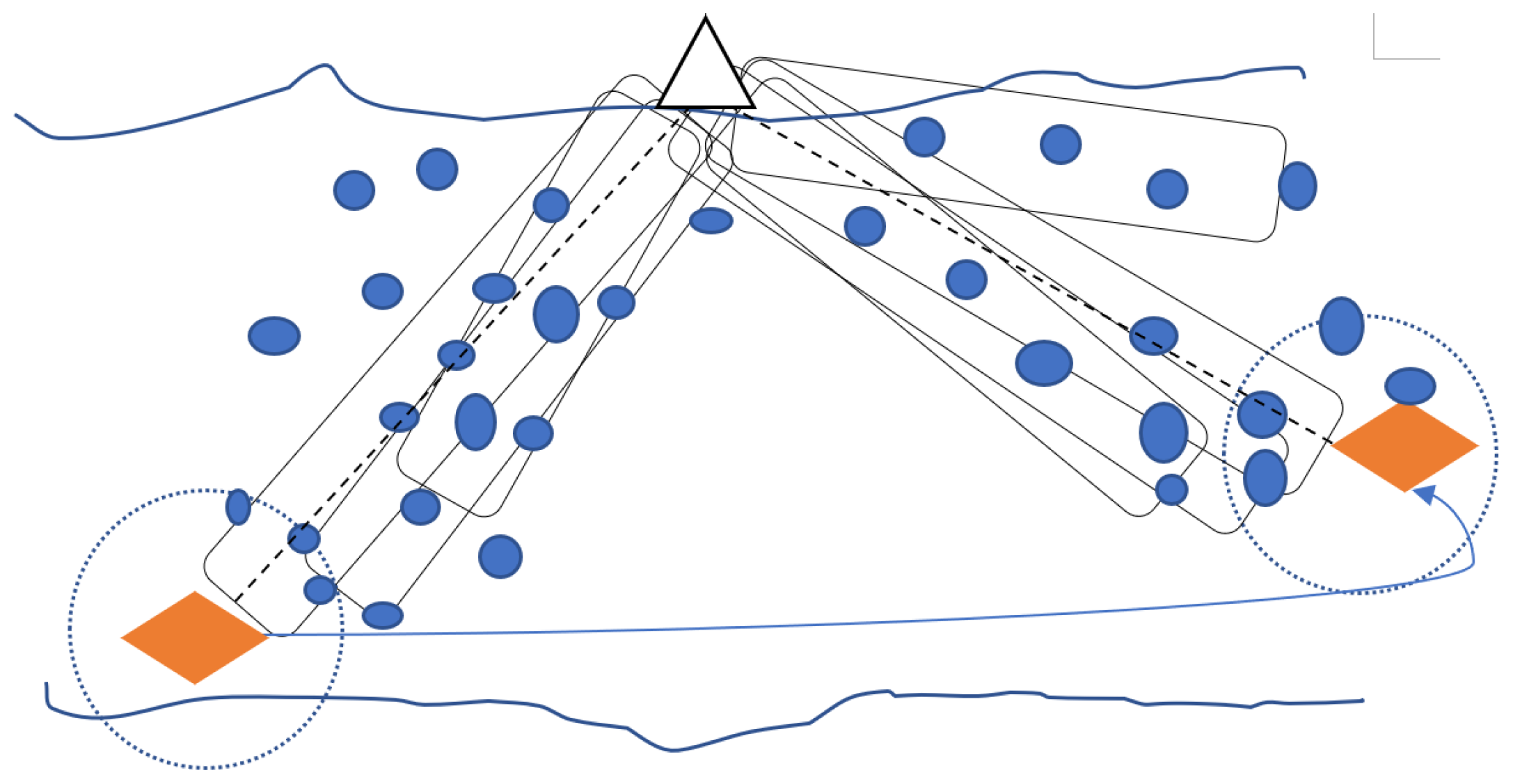
When nodes perform data transmission, the nodes inside the virtual pipeline can be used as candidate relay nodes, while the nodes outside the virtual pipeline can no longer be used as candidate relay nodes. As shown in Figure 4, when the node holding the data packet successfully transmits the data to the relay node, the relay node will act as the new node holding the data packet, and at this time, a virtual pipeline between the node and the Sink node is established again.

4.2. Setting of Candidate Relay Nodes

In the above, we have introduced in detail how to establish a virtual pipeline when a node forwards data. In this part, we will introduce how to determine a candidate relay node when a node within a certain pipeline forwards data. Before the sending node data, it first sends a request information packet, which requests all node location information, energy information and candidate relay node information around the sending node. Nodes in M-UWSNs are defined as Formula (10):
N = n 1 , n 2 , n 3 , , n m
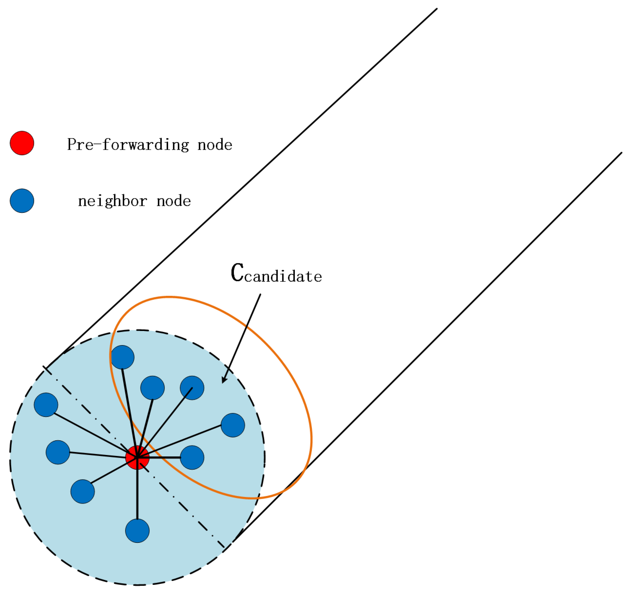
n and m, respectively, represent the sensor node and sensor node number, as shown in Figure 5:
N i is the node that pre-forwards data, first find the neighbor node of N i , when n j satisfies the Formula (11), it will represent the neighbor node belonging to n i :
N i n j R , n j N
after finding the neighbor nodes of N i , all neighbor nodes need to judge whether they belong to the nodes in the virtual pipeline established by N i and Sink node. As shown in Figure 3, the angle between N i n j and N i S i n k is θ j . When the θ j satisfies Formula (12), it means that n j belongs to the node in the virtual pipeline established by N i and the Sink node, that is, n j is the candidate relay node when N i node pre-forwards data:
0 θ j π 2 n j C c a n d i d a t e
C c a n d i d a t e represents the set of candidate relay nodes of the sending node N i . All candidate relay nodes of N i can be selected according to the above formula. At the same time, in order to prevent the candidate relay node from drifting out of C c a n d i d a t e due to the movement of ocean currents, which leads to the problem of routing holes. All candidate relay nodes will calculate their own candidate relay node number N u m c a n and pass it to the pre-forwarding data node. Larger N u m c a n means that the more relay nodes can be selected, the less possibility of routing holes.

4.3. DDQN Algorithm Based on Empirical Priority

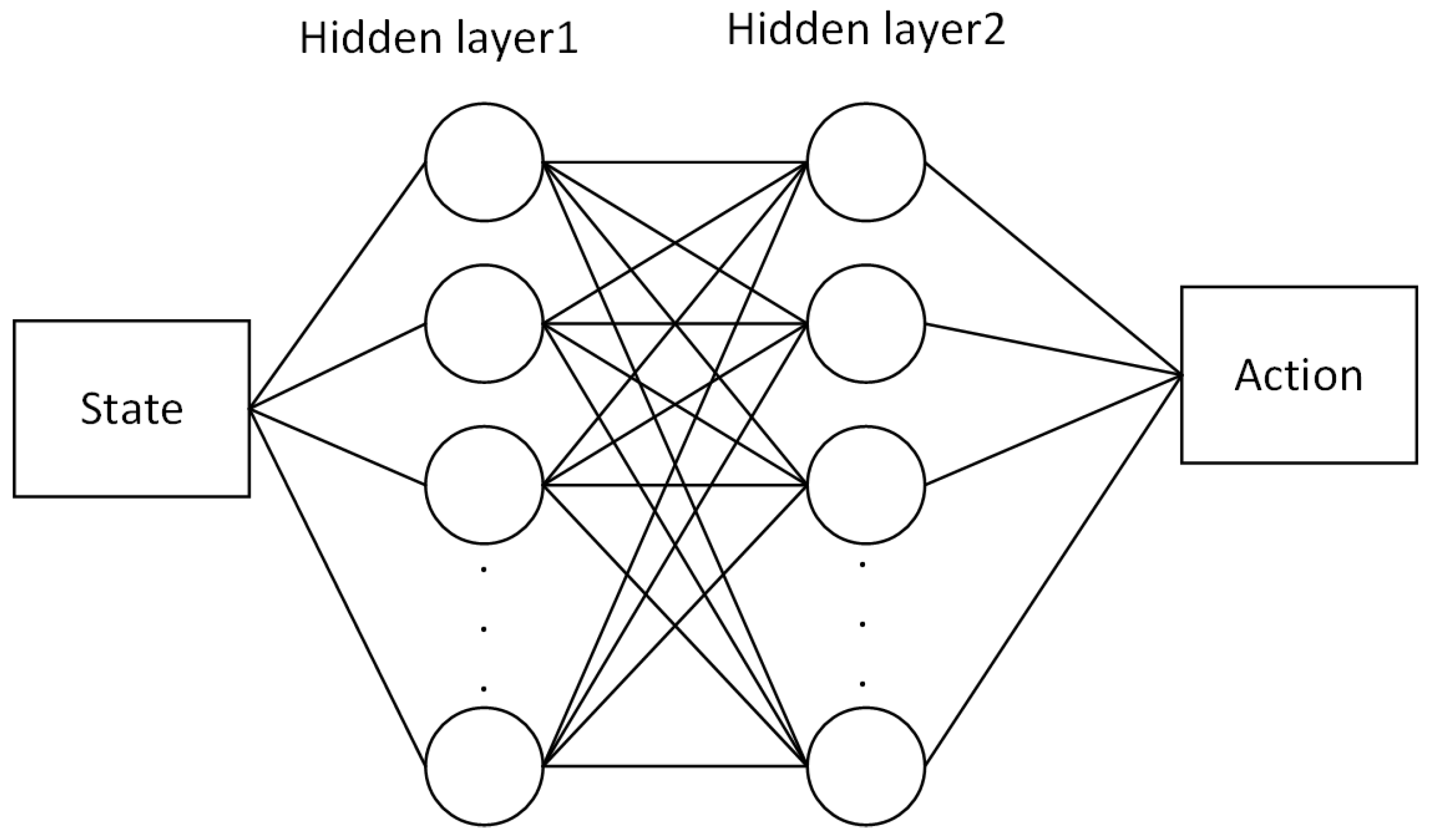
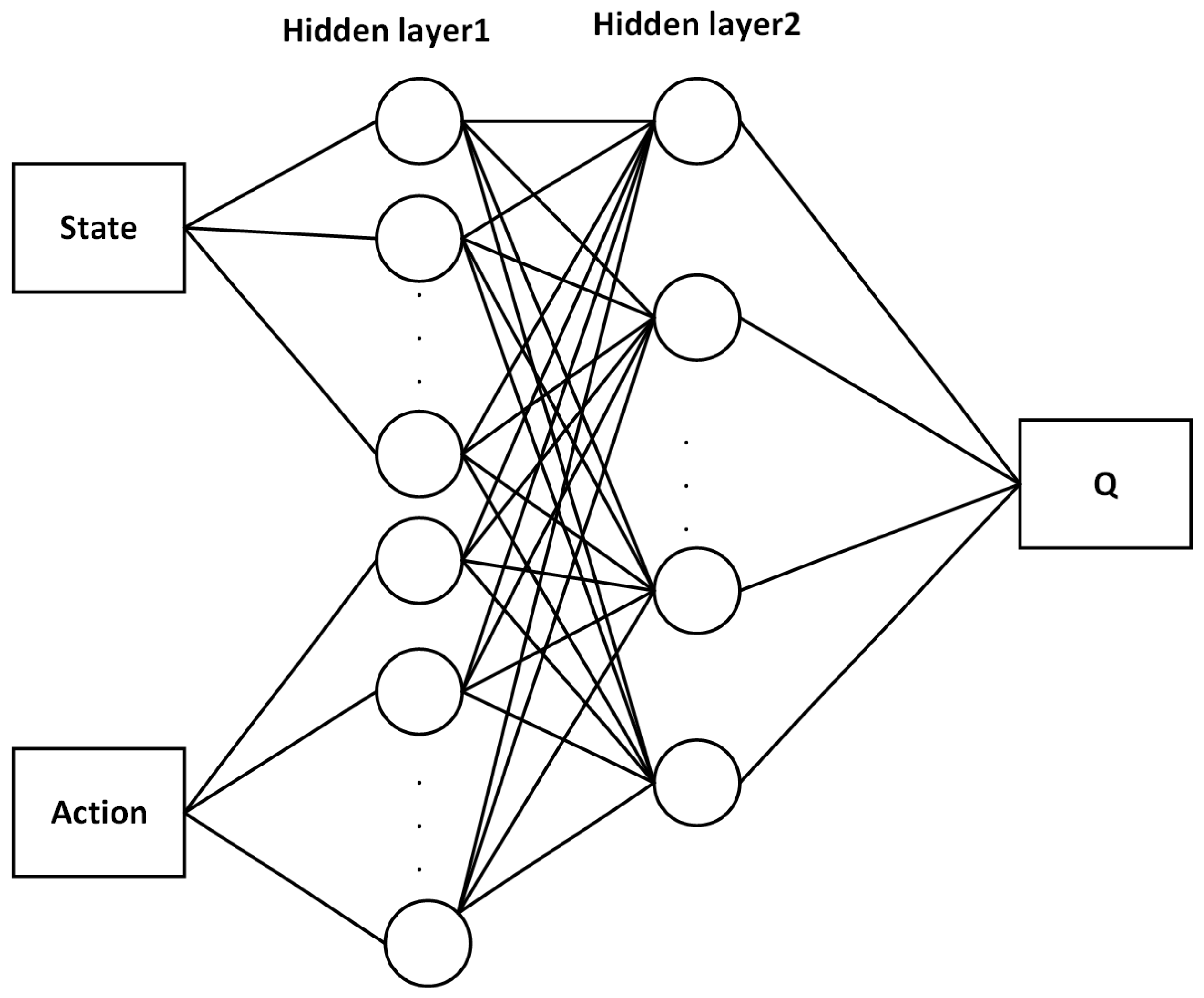
This part will detail the deep reinforcement learning algorithm used in the PDDQN-HHVBF protocol. The pre-forwarding data node will select the optimal relay node according to the predicted reward value of the neural network parameters obtained from the training, specifically using the DDQN based on the priority experience value playback. The neural network used in this method mainly includes two parts: the current network and the target network. Among them, the current network is mainly responsible for the current state s of the root candidate relay node to give the action a to be executed, the network is optimized based on the policy gradient. In addtion, the target network is the evaluation of the output action a of the current network in the state s. The target network is based on a value function. In the routing decision problem solved in this paper, the current network adopts a four-layer structure, and the network uses a fully connected network. The state s is used as the output layer, the second and third layers are hidden layers, and the last layer is the output of action a. In this network, the hidden layer uses the ReLu activation function for nonlinearization, and the output layer uses the Tanh activation function for nonlinearization, where the output range is ( 1 , 1 ) , and the current network of the strategy is shown in Figure 6. The target network also uses a four-layer network structure, and also uses a fully connected structure. The state–action pair ( s , a ) is used as the input layer, the second layer and the third layer are used as the hidden layer, and the last layer outputs the evaluation value Q of the state and action pair. The target network is shown in Figure 7.
The experience replay mechanism mentioned above can avoid the strong correlation between data samples to a certain extent, but this method is not efficient to a certain extent, because the importance of the samples is not the same, making the agent learning efficiency is not the same. Therefore, the researchers proposed a priority-based experience playback mechanism, that is, when extracting samples from the experience pool during the experience playback process, the samples are sorted and sampled according to the value of the sample priority r a n k i from large to small. However, the samples sampled by the pool are too concentrated, which makes the error shrinking slowly and the training time is too long. Especially in the process of function estimation, the samples with high initial training errors will be frequently used in the network, which will make the learning results overfit. In response to the above problems, this paper takes advantage of the random uniform sampling of priority playback and the ε g r e e d y . The random sampling method is introduced into the priority playback mechanism so that the playback samples will not be too concentrated and lead to overfitting. The sampling probability of sample i is defined as Formula (13):
P ( i ) = r a n k α k r a n k α
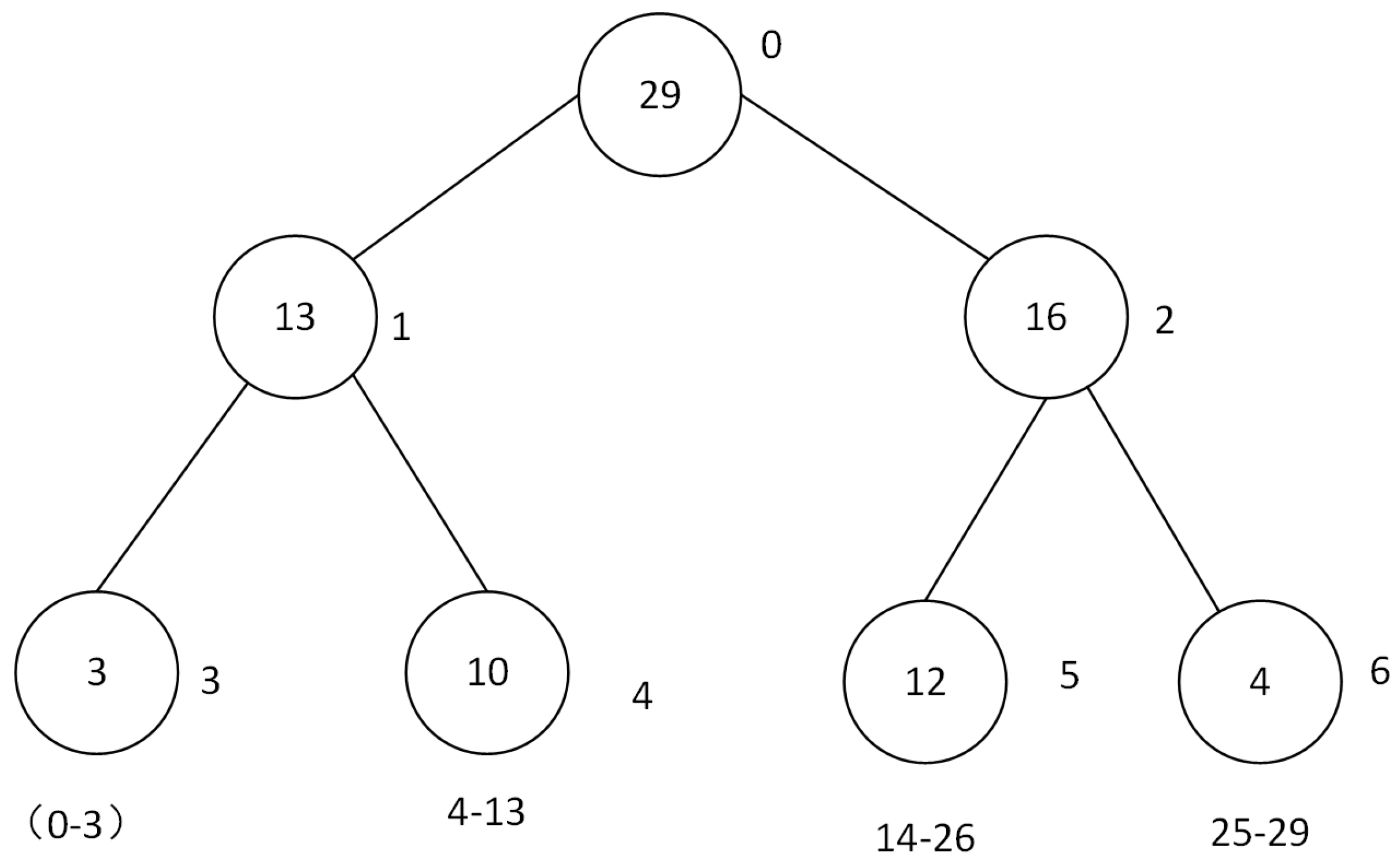
in the above formula, r a n k α is the priority of sample i, α is the priority sampling factor, when α is 0, the sampling method is random uniform distribution, when α > 0 , it will not always sample with the high error data. Because the research scenario of this paper is a large-scale M-UWSNs routing problem, the required sample pool will be large. During the process of storing and sampling samples, the search and sorting of samples will make the algorithm too complex, resulting in slow convergence of the algorithm and waste a lot of time in the calculation process. Based on this problem, this paper uses the binary tree structure of SumTree to store and find samples to reduce the time of searching and sorting. The structure diagram of SumTree is shown in Figure 8.
As shown in Figure 8, all the experience playback samples are stored in the leaf nodes in SumTree, each leaf node represents a sample, the leaf node not only saves the data, but also saves the priority of the sample. The internal nodes in the tree do not save sample data, and the number of internal nodes is the sum of the priorities of their two child nodes. When the system samples, first divide the leaf nodes of the entire SumTree into multiple intervals according to the total priority and the number of samples, as shown in the figure. The area calculation method is as Formula (14), and then each interval is sampled with a sample. Then, sampling from top to bottom. If sampling is required, follow the procedure in Table 1.
n = sum ( P ) b a t c h s i z e

4.4. Selection of the Optimal Relay Node

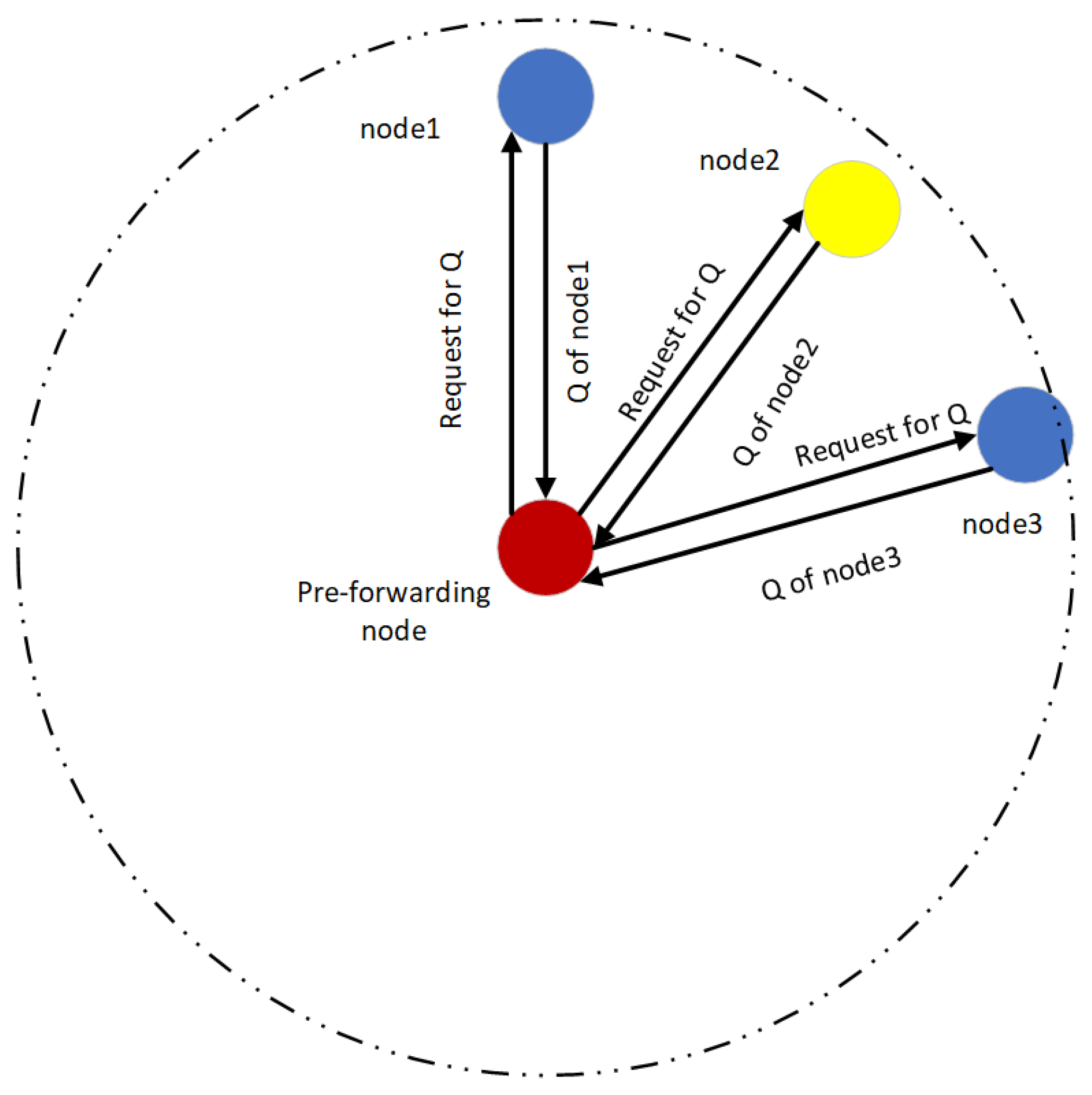
This part will specifically introduce how to select a relay node for forwarding based on the DDQN algorithm based on empirical priority after the candidate relay node set is determined above. The PDDQN-HHVBF routing protocol provides a complete execution process for the data packets from the AUV to the Sink node. In this paper, it is assumed that nodes can obtain their own residual energy and three-dimensional coordinates in M-UWSNs. In addtion, all nodes in M-UWSNs will drift due to the movement of ocean currents, but the moving distance is limited in a short time, that is, the network topology is stable relatively in a short time. Compared with the long routing propagation time in the underwater acoustic channel and the high energy consumption, the delay and energy consumption of calculating the Q value are very low, so it is not calculated separately in this paper. The process of requesting the Q value is shown in Figure 9.
As shown in Figure 9, the pre-forwarding node requests the Q value of the candidate relay nodes before sending data, and the request packet carries the location information of the pre-forwarding node so as to calculate the location parameter of the Q value. After receiving the request, candidate relay nodes calculates the Q value and returns them to the pre-forwarding node. After receiving the Q value of the candidate relay nodes, the Source node selects the node with the largest Q value as the relay node to transmit data, that is, node 2 in Figure 9. Each node in M-UWSNs can be regarded as an agent. The position information, energy and number of candidate relay nodes of each sensor node can be regarded as the current state. The forwarding of the relay node selected by the sending node can be regarded as the action taken by the agent according to the state, and a Q value will be obtained each time the data packet is forwarded to the relay node. In this protocol, a data packet needs to obtain the Q value of the candidate relay node, so it first sends a request Q value packet to all candidate relay nodes, and the candidate relay node calculates the Q value and returns the value to the sending node. The sending node selects the candidate relay node with the largest Q value to forward the data, and then the chosen node forwards the data to the Sink node hop by hop according to this method. When the node calculates the Q value, it needs to obtain the residual energy, location information, and the number of candidate relay nodes. The formula of residual energy is as Formula (15). The location information is α , in reference [13], as shown in Formula (16). The number of candidate relay nodes is N u m c a n , which is the number of candidate relay nodes.
r sen = e own e max
α = R d sin θ j R
in Formula (15), e own is the existing energy of the node, e max is the initial energy of the node. In Formula (16), as Figure 3, R refers the radius of the pipeline, d is the distance that the pre-forwarding node deliveries data to the relay node, and θ j represents the angle between n i n j and n i S i n k .
The larger r s e n , the more the residual energy of the node, which means that the node is used less frequently. In addtion, subsequent use of nodes with large r s e n also does not lead to energy exhaustion and end of lifetime of M-UWSNs. In addition, it is specified that the virtual pipeline radius R is fixed, the size of α is determined by d and θ j , and the value of α is inversely proportional to d s i n θ j . When d s i n θ j is smaller, α is larger. The shorter the transmission distance between nodes, the smaller the collision probability. When the transmission distance d is constant, the smaller the θ j , the closer the candidate relay node is to the Sink node, and the higher the probability of successful data forwarding. N u m c a n is the number of candidate relay nodes. The larger N u m c a n is the more relay nodes can be selected, and the less possibility of routing holes due to ocean current movement. Therefore, the strategy of the PDDQN-HHVBF protocol proposed in this paper is to find candidate relay nodes with large α , large r s e n , and large N U M c a n for routing and forwarding. Therefore, the reward function [32] is calculated by the above α , r s e n , N U M c a n , where the reward function R ( s i , a i ) is generated by each state and action pair of the candidate relay node. The return value is set as Formula (17):
R s i , a i = c α + b r s e n + a N u m c a n
where a, b, c are the weight parameters of α , r s e n , N u m c a n , respectively. The neural network trains convergence parameters through training iterations. Since the return value of other nodes is between 0 and c, and the r s e n of the Sink node is always set to be 1, the original setting of this value is that when the node can directly transmit data to the Sink node. In this way, nodes will be preferentially transmitted to the Sink node, so as to avoid data looping. Therefore, the node avoids selecting nodes with lower residual energy while reducing the number of detours. More residual energy r s e n , higher α , and more N u m c a n is the strategy when looking for relay nodes.

4.5. “Store-Carry-Forward” Mechanism

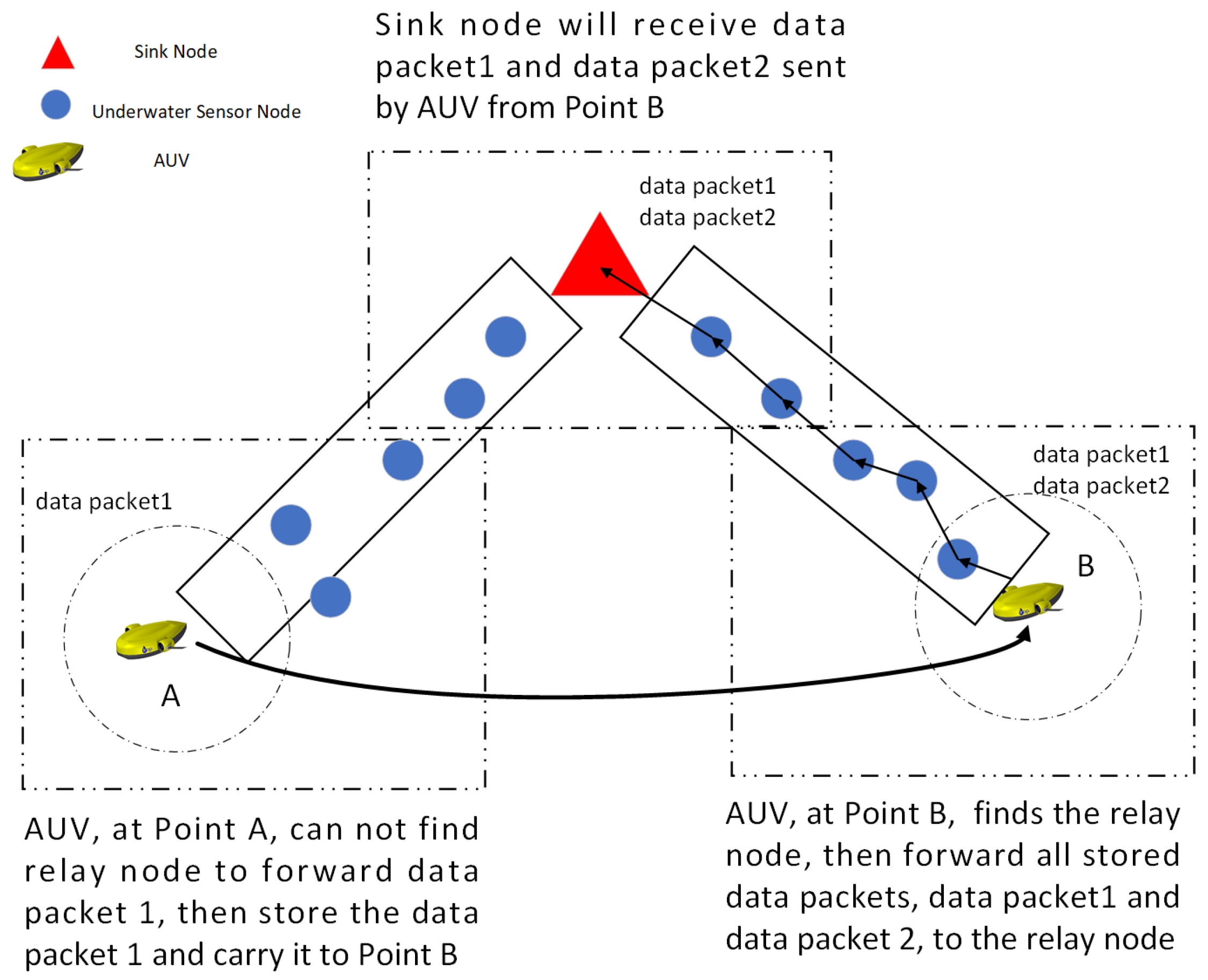
In this part we will introduce the “Store-Carry-Forward” mechanism of AUV. After the AUV data are collected, the data packets will be forwarded hop-by-hop to the Sink node. However, during the transmission of data packets, ocean current movement may cause all candidate relay nodes within the AUV transmission range to drift out of the AUV transmission range, which will lead to failure of AUV data packets transmission. If the AUV continues to re-transmit data packets in this area until the data transmission is successful, it will lead to a large waste of AUV energy. Or, the performance of all candidate relay nodes is very poor. If AUV transmits data to the relay nodes with low Q values, it is very likely that routing hole will occur, which will eventually lead to data packets loss. Therefore, “Store-Carry-Forward” mechanism makes AUV not forward data temporarily when it cannot find a suitable relay node, but continue to store and carry the packet and continue to collect new data packets according to the track until it finds a suitable relay node. Then, the AUV forwards all stored data packets to the suitable relay node.
As shown in Figure 10, the AUV will transmit the data packet1 to the Sink node after collecting the data at the Point A. However, there is no suitable relay node in the AUV transmission range. Then, the AUV activated the “Store-Carry-Forward” mechanism to store and carry the data packet 1 to point B. During the movement from Point A to Point B, the AUV continues to detect data, that is data packet 2. After reaching Point B, the AUV starts an operation to find the relay node. If the situation is the same as at point A, it will continue to carry the two data packets to the next forwarding location. But the AUV can find a suitable relay node at point B as Figure 10, the AUV will transmit the two data packets to the relay node together. Then the Sink node will receive the two data packets, data packet1 and data packet 2 sent by the AUV from Point B.
5. Performance Analysis and Simulation

5.1. Network Frame and Simulation Settings

In this section, numerical experiments are presented to evaluate the performance of PDDQN-HHVBF underwater, the experiments are based on NS2’s network sensor simulation platform, namely, Aqua-sim [32]. Each node in the M-UWSNs used in this paper has its own unique ID, and the limited energy is specified in the 3D deployment distribution area. In the simulation experiment, the M-UWSNs area is set to 1000 m × 1000 m × 500 m, and the range of the number of nodes is 500–3000. Figure 11 is the distribution of 500 nodes in this M-UWSNs model. The simulation scenario of the routing decision algorithm is set as Figure 10. The nodes are arranged in the application scenarios according to the task requirements. In the Figure 10, the solid red dot is the Sink node, and the location coordinate is (500, 500, 500), the blue nodes are general wireless sensors, which are responsible for collecting data and forwarding data, the black nodes is AUV. As shown in the Figure 10, the initial coordinate of the AUV is (10, 10, 10), and then the AUV moves the exploration data to (900, 900, 10). The simulation ends when the 1000 packets sent by the AUV are received by the Sink node or lost. The specific parameters used in the experiment are as follows:

5.2. Network Performance Metrics

This part will introduce four network performance indicators for comparison in the following simulation experiments: these four network performance indicators are packet delivery ratio PDR, Energy Tax, End-to-End Delay, and network lifetime.
(1) PDR: this indicator refers to the success rate that the AUV transmits the final Sink node hop-by-hop after collecting the data packet in the M-UWSNs. The calculation method is as Formula (18):
P D R = R packets s packets
(2) Energy Tax: This indicator represents the average energy consumption of the system after each node transmits data packets to the Sink node, that is, the average energy consumption of the system when the Sink node successfully receives data packets. The specific calculation method is as shown in Formula (19):
Energy Tax = E consumed Num nodes R packets
(3) End-to-End Delay: The end-to-end delay is the average time consumed by a packet sent from the AUV until it is received by the Sink node.
(4) Lifetime: Lifetime means that one node in the M-UWSNs runs out of energy, and the M-UWSNs cannot continue to operate.

5.3. Comparative Analysis of Simulation Results

In this part, we compare the PDDQN-HHVBF protocol with the state-of-the-arts, which are VBF [12], HHVBF [13], DQELR [3], and ROEVA [29].
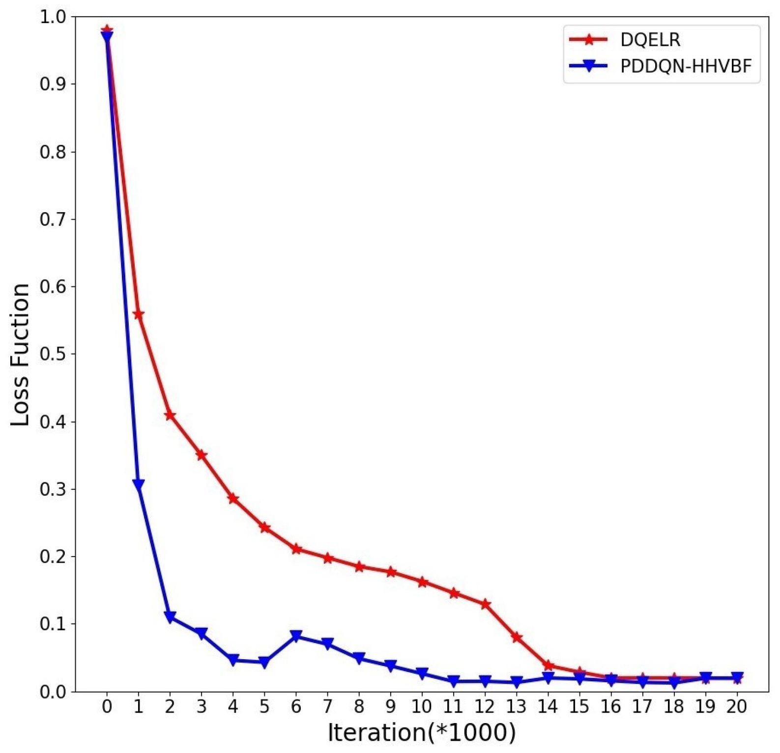
Firstly, we study the performance of DQELR and PDDQN-HHVBF in the convergence speed as shown in Figure 11. In this experiment all nodes move randomly at the speed of 0–3 m/s under the influence of ocean current movement. As the number of iterations increases, the DQELR loss converges to about 16,000 rounds, while the convergence speed of PDDQN-HHVBF proposed in this paper increases by about 30%, and has converged in 11,000 rounds. This is because PDDQN-HHVBF uses the DDQN algorithm based on empirical priority, while DQELR is based on the DQN algorithm. The DDQN algorithm based on empirical priority can avoid the strong correlation between the data samples. It can also avoid the phenomenon of overfitting caused by over-concentration of samples sampled from the experience pool. Therefore, compared with the DQELR protocol, PDDQN-HHVBF has less computational overhead and shorter network delay in network training.
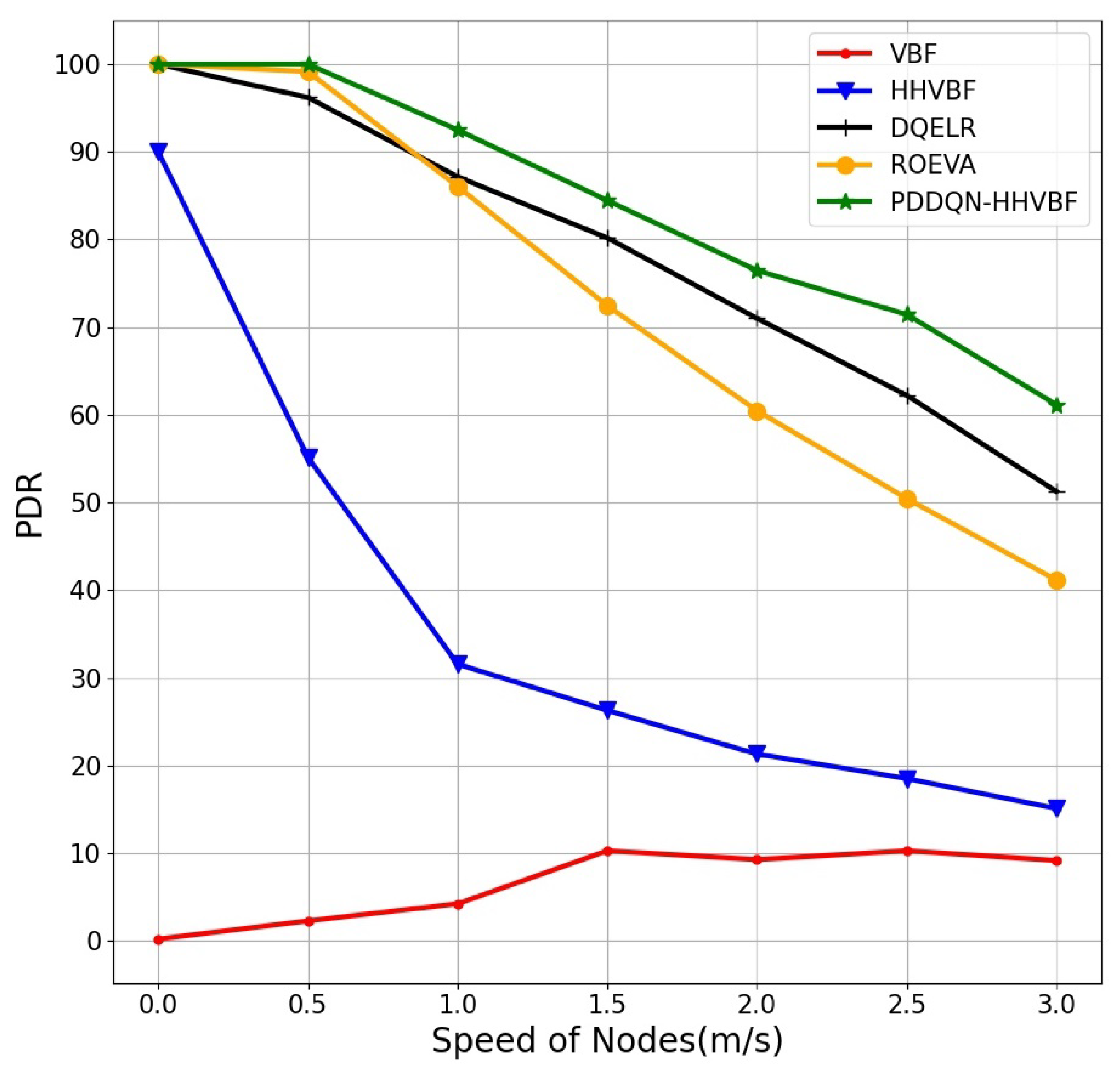
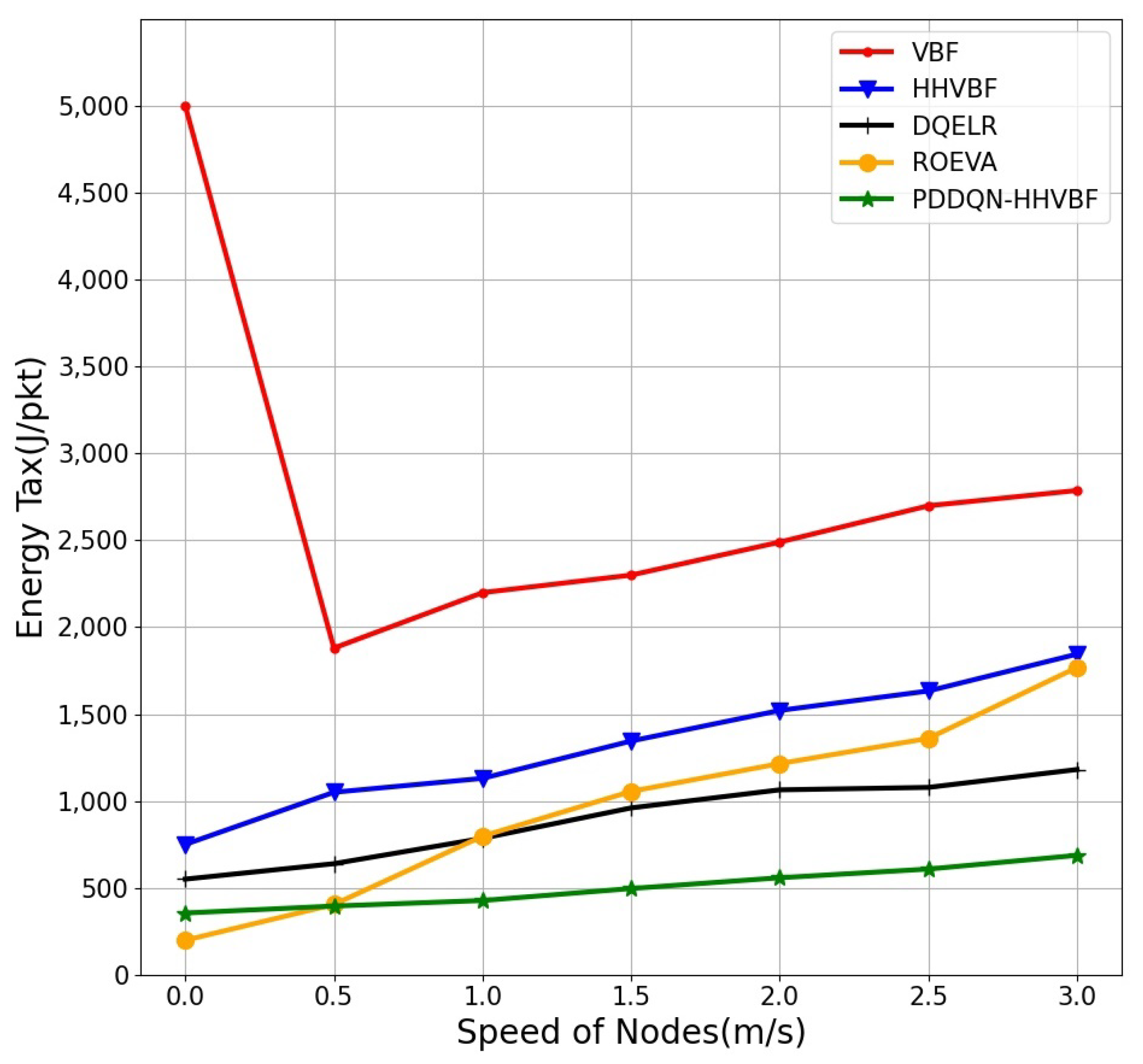
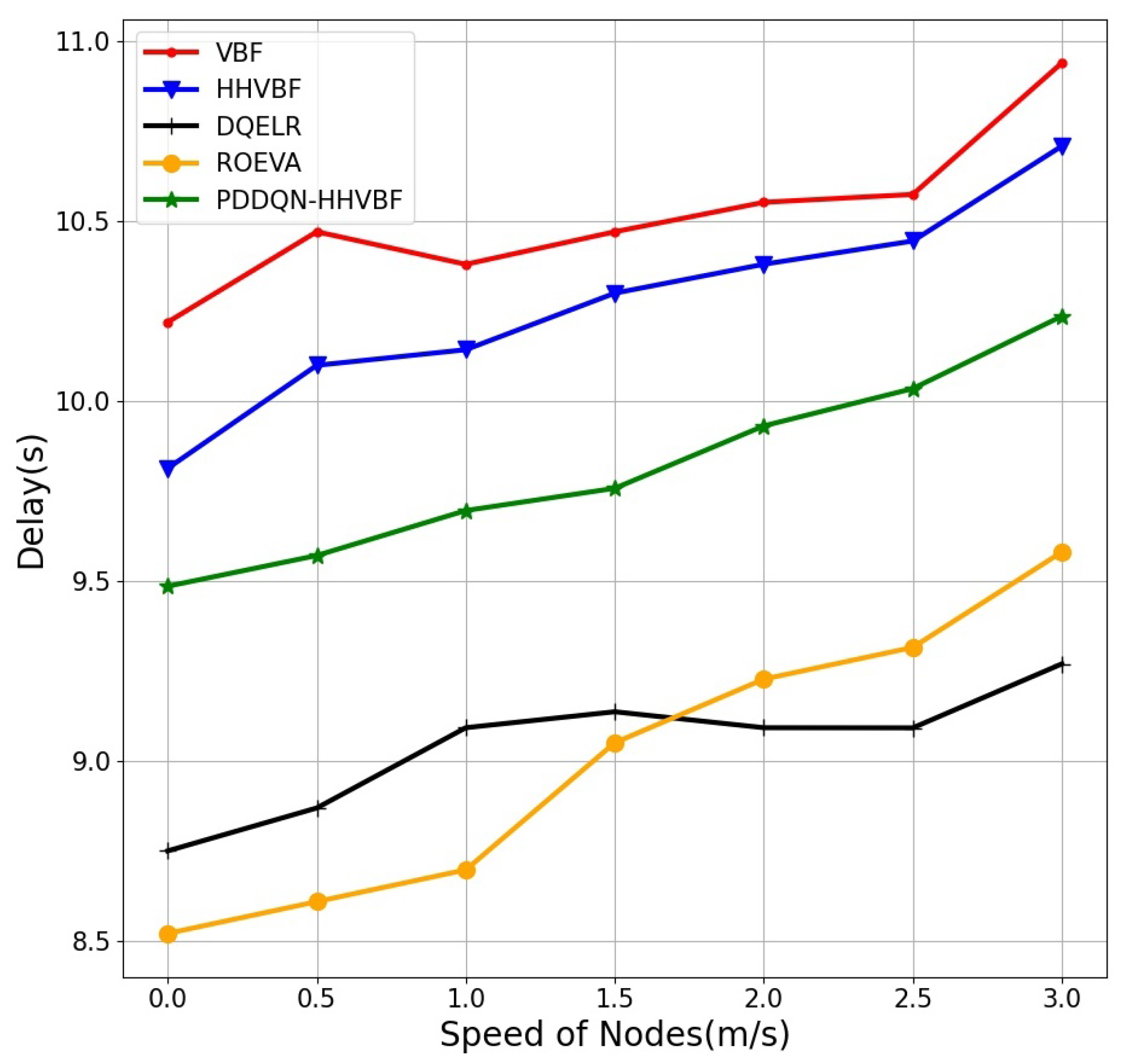
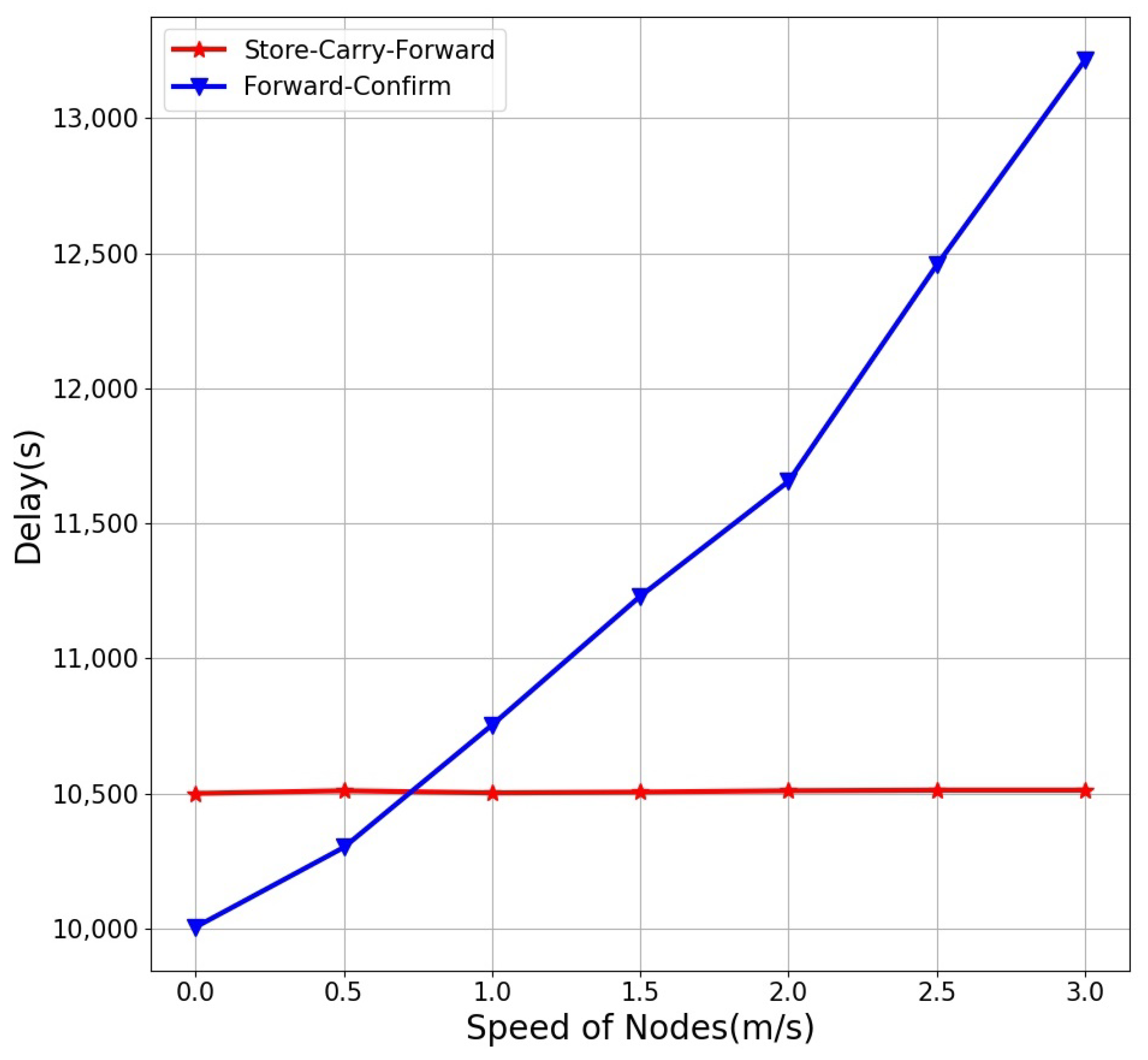
The random movement of nodes due to ocean current movement is a major cause of data packets loss in M-UWSNs, so we explore how the free movement speed of node will affect PDR, energy tax, end-to-end delay of the five algorithms as Figure 12, Figure 13 and Figure 14. We fixed the network size as 1000 nodes (a relatively sparse network). In addition, in this environment, we will also compare the impact of the “Store-Carry-Forward” mechanism and the “Send-Confirm” mechanism used by AUV on the energy consumption of AUV Figure 15.
It can be seen from Figure 12 that when the nodes move randomly, the VBF cooperative PDR is obviously the worst. This is because there are fewer nodes in the pipeline when the VBF transmits data, and there will be routing holes, resulting in a very low PDR. The HHVBF protocol has a higher PDR than the VBF protocol due to the recalculation of the pipeline for each node that receives data. However, it performs poorly after random movement of nodes. DQELR, ROEVA and PDDQN-HHVBF perform better in this environment. However, when the nodes move fast, the PDR of DQELR and ROEVA decreases significantly, especially the ROEVA protocol. This is because the REOVA protocol does not consider the impact of the ocean current movement on the node movement, but only considers the historical Q value of the candidate relay node for relay node selection. Based on above principle, the ROEVA protocol is likely to delivery data packets to the relay node with the historical largest Q value, but this node may becomes a routing hole due to the influence of ocean current movement. Hence, when the nodes moves fast (over 1 m/s), the PDR of the ROEVA is significantly lower than that of PDDQN-HHVBF protocol in this paper. About the DQELR protocol, although considering the movement of nodes, it still use historical Q value of the candidate relay nodes. Although the DQELR better than the ROEVA about PDR under this circumstance, it still worse than the PDDQN-HHVBF protocl. In addition, the other protocols compared with the PDDQN-HHVBF does not consider the situation of the AUV sending data packets. When the AUV cannot find the relay node, the data packet will be lost. The PDDQN-HHVBF protocol performs best in this experimental environment due to the consideration of the number of candidate relay nodes for relay nodes and the “Store-Carry-Forward” mechanism. Considering the number of candidate relay nodes, the data packets can be forwarded as far as possible to the node that can successfully forward the data packet to the Sink node and has the smallest probability of routing holes due to the movement of ocean currents. The “Store-Carry-Forward” mechanism enables the AUV to find a suitable relay node and avoids data packets loss from the AUV.
We continue to explore how the mobility of nodes will affect the energy tax of the five algorithms. In the Figure 13, as the speed of node movement increases, the energy tax of the five algorithms also increases. This is because node mobility reduces the PDR, so more energy is spent to transmit successful data packets. In this experimental environment, the energy tax of VBF protocol and HHVBF protocol is significantly higher than that of DQELR protocol, the ROEVA protocol and the PDDQN-HHVBF protocol. This is because both VBF and HHVBF protocols use broadcast methods to send data packets, which will result in repeated reception of packets and data packets collision. In addition, these two methods do not consider the problem of data path, so data packet is often forwarded to the routing holes, resulting in packets loss and re-transmission consuming a lot of energy. About the ROEVA protocl, it also use broadcast methods to send data packets. Because it considers the historical Q value by energy, PDR and end-to-end delay, it performs better than the VBF and the HHVBF. However, it just consider the static node, not the mobility of nodes. Thus, it performs worse than the DQELR and the PDDQN-HHVBF in this circumstance. The DQELR protocol consumes less energy because of its uni-cast strategy of finding the optimal relay node. However, in this experimental environment, there will still be re-transmission packets and data collisions caused by packets loss. Thus, the energy tax is larger than the PDDQN-HHVBF protocol proposed in this paper. The PDDQN-HHVBF protocol proposed in this paper is the best performing protocol among the five protocols. It not only has a lower energy tax, but also has a stable trend and the best robustness. This is because the PDDQN-HHVBF protocol has the highest PDR in this network environment, the least packets loss, and the least number of data re-transmissions and collisions, so it consumes less energy.
Then, we explore how the mobility of nodes will affect the end-to-end delay of the five algorithms. In the Figure 14, as the speed of node movement increases, the end-to-end delay of the five algorithms also increases. This is because the number of data packets re-transmissions increases due to the node movement, which makes the delay increase with the node movement speed.In this experimental environment, the end-to-end delay of VBF protocol and HHVBF protocol is significantly higher than that of other three protocols. It is because that both VBF and HHVBF protocols will repeat receiving of data packets and data packet conflicts, thus increasing the number of data re-transmissions and delay, especially when the node movement speed increases. The protocol proposed in this paper needs to query the Q value of candidate relay nodes, which leads to spending extra time in Q value request and reply, so the delay is higher than the DQELR and the ROEVA. This because the Q values of the DQELR protocol and the ROEVA protocol consider the link delay, these two protocols perform best in the delay indicators. When the node moves at a low speed, the ROEVA performs better than DQELR. However, when the node moves at a faster speed, the ROEVA does not consider the node mobility, resulting in a higher delay than DQELR. Overall, the DQELR performs best in end-to-end delay influenced by high mobility of nodes.
Then, in this environment, we compare the energy consumption of the AUV “Store-Carry-Forward” method and the AUV “Forward-Confirm” method of sending data packets. When using the “Store-Carry-Forward” method, the energy consumed by each data packet of the AUV is: 10 J for data transmission, 0.5 J for requesting Q-value control packets, and 0.05 J for receiving and returning Q-value control packets. If there is no suitable relay node, it will not forward the data and continue to detect new data until the AUV finds a suitable relay node to forward. When the AUV uses the “Forward-Confirm” mechanism to send a data packet, the AUV will wait for the node to receive a successful return confirm packet. As shown in Figure 14, the energy consumption of the AUV using the “Store-Carry-Forward” mechanism to send 1000 data packets fluctuates around 10,500 J, while the AUV using the “Forward-Confirm” mechanism accelerates the random movement speed of the node. As a result, the AUV re-transmits data packets multiple times and wastes a lot of energy.
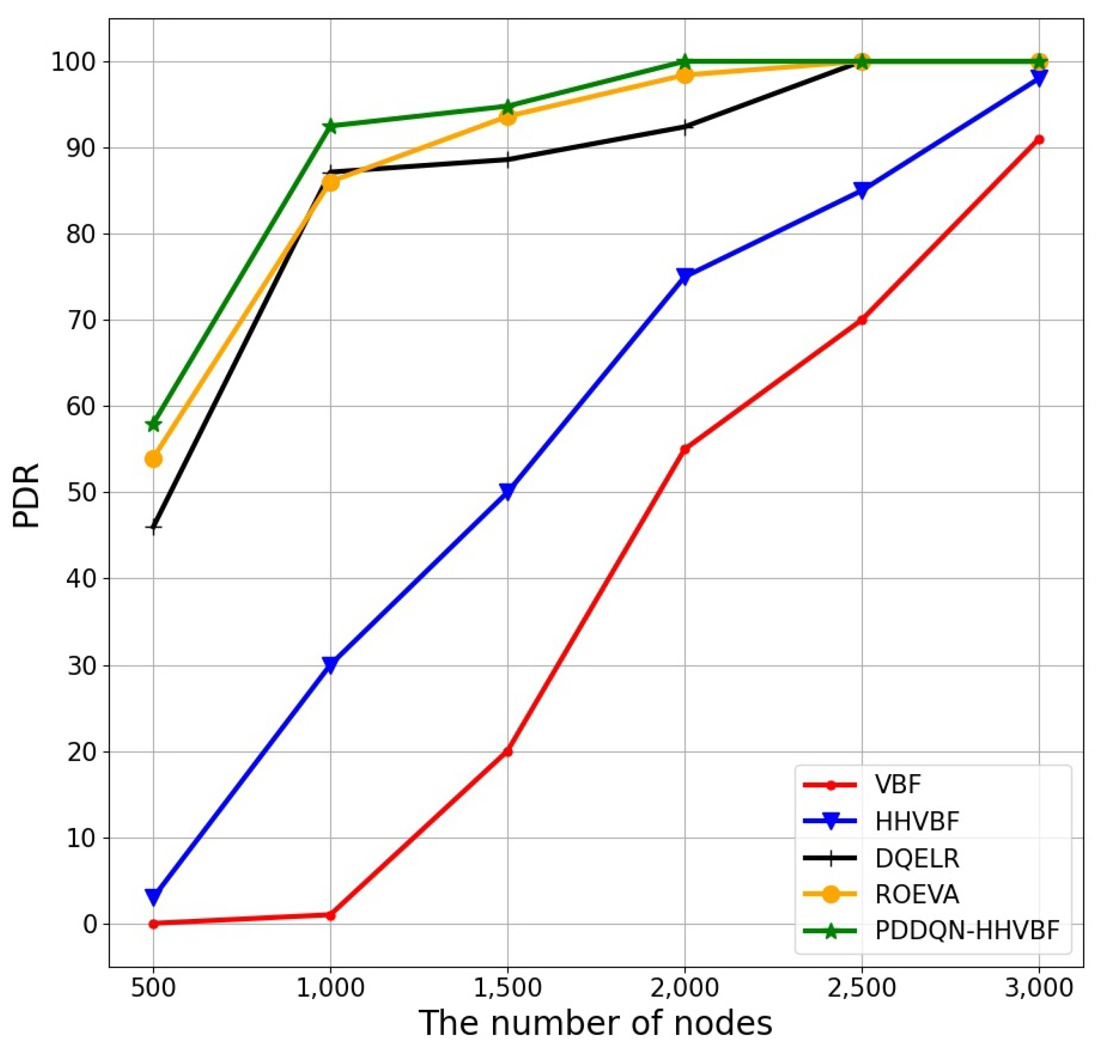
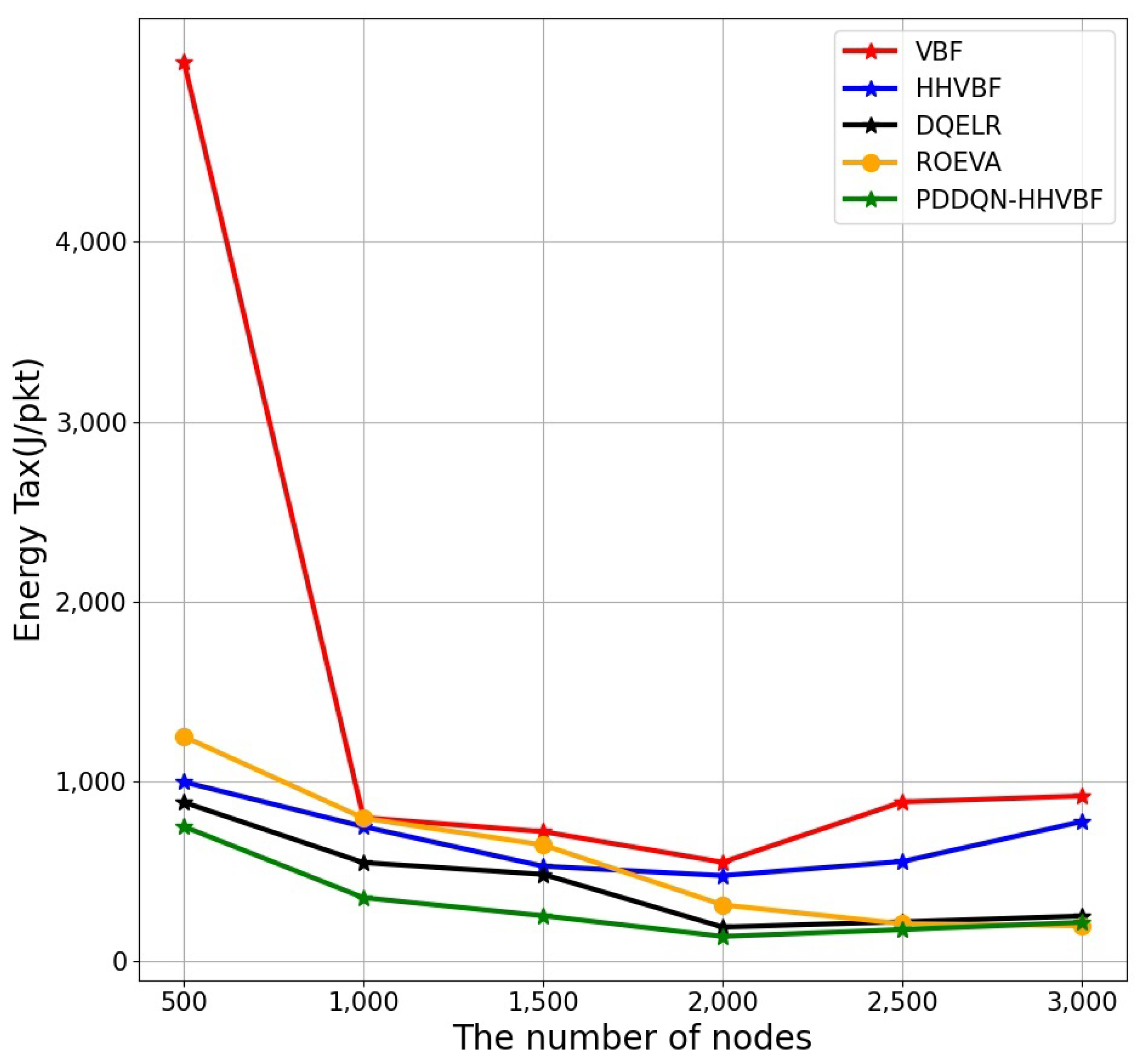
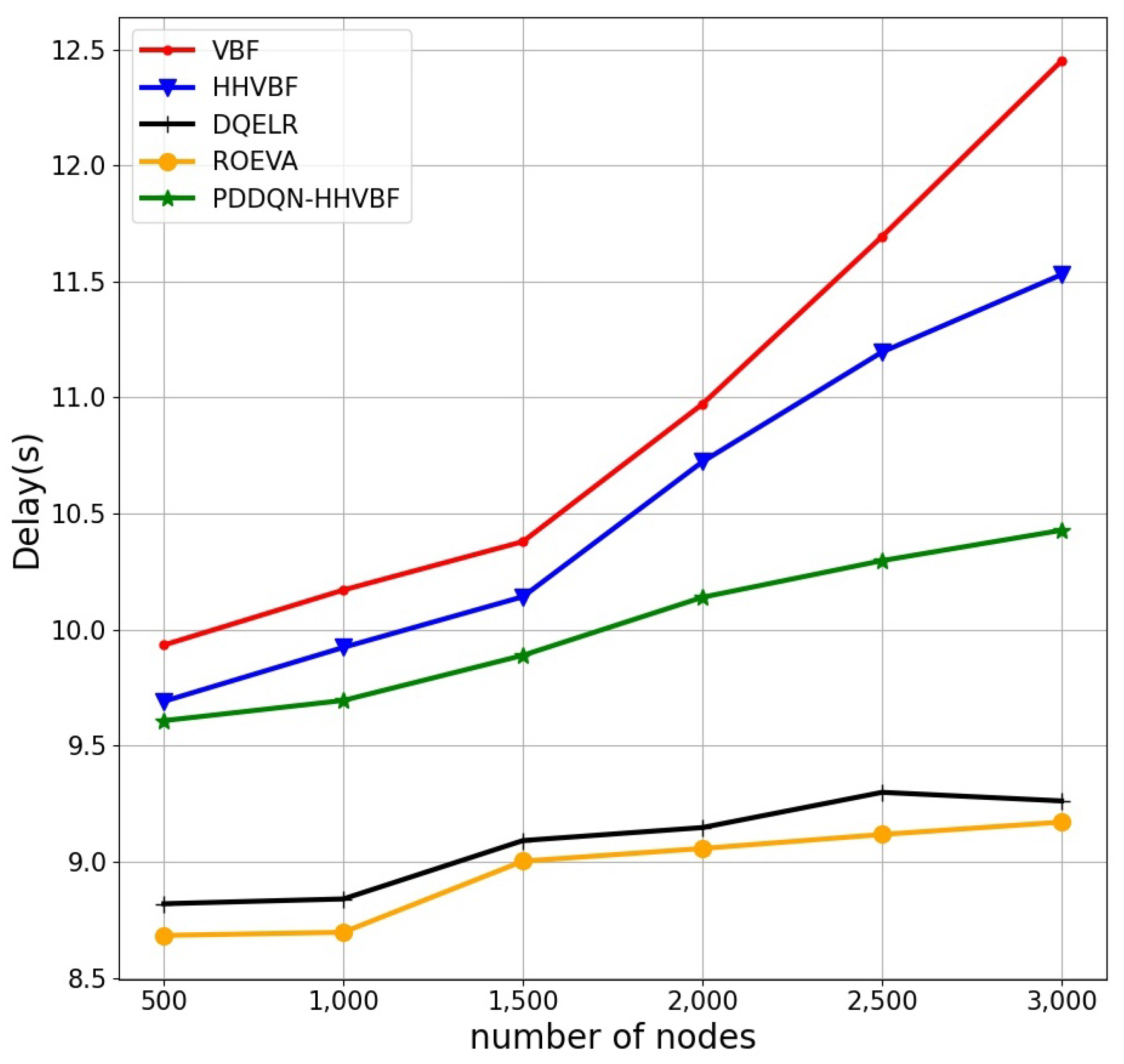
In the following experiments, we explore how the number of nodes in M-UWSNs affects the PDR, energy tax, end-to-end delay and Lifetime metrics of the five algorithms. The number of network nodes is 500–3000, and the nodes’ moving speed is fixed at 1 m/s.
In Figure 16, VBF protocol PDR is very low. The reason is that the failure to find a suitable relay node leads to packets loss, and the performance of the VBF protocol is still the worst even when the number of nodes increases. The HHVBF protocol performs much better than the VBF protocol, but still much worse than those protocols using reinforcement learning to find the optimal relay nodes. Comparing the other protocols that use reinforcement learning to find the optimal nodes in sparse M-UWSNs, the PDDQN-HHVBF protocol performs best. The reason is that the proposed protocol can find the optimal nodes according to the in-time number of candidate nodes, but the two protocols use historical Q value to find the relay nodes, which will be moved by ocean current movement. In addition, the proposed protocol also use the “Store-Carry-Forward” mechanism, which makes the data packets transmitted by AUV store the data until a suitable relay node is found and forward it if there is no suitable relay node, which reduces the probability of packets loss. When the number of nodes in M-UWSNs is greater than 2500, the PDR of three protocols which use reinforcement learning reach 100%. Therefore, these using reinforcement learning protocols have greater performance in PDR under large-scale M-UWSNs.
Figure 17 shows the energy tax trends of the five protocols as the number of nodes increases. When the number of nodes is sparse, the energy tax of the VBF protocol is very large. The reason is that the failure to find a suitable relay node leads to multiple re-transmissions and wastes energy. Even when the number of nodes increases, the performance of the VBF protocol is still the worst. The HHVBF protocol performs much better than the VBF protocol when the number of nodes is small. However, when the number of nodes is greater than 2000, the energy tax performance of the HHVBF protocol begins to increase. This is due to the fact that the number of nodes is too large and the packets is collided and re-transmitted many times. Comparing those use RL protocols, the proposed protocol performs best in sparse network. However, when the number of nodes is greater than 2500, the performance of these three protocols in PDR is very close. The reason is that they all consider energy consumption of nodes. Different from the compared protocols use the historical Q value, the PDDQN-HHVBF protocol considers the real-time Q value related to the the geographical location information, which will allow packets to be propagated over short distances in M-UWSNs. Thus, in the PDDQN-HHVBF protocol, re-transmits data packets fewer times due low packets collision. Therefore, it consumed less energy to forward data packets.
Figure 18 shows the end-to-end delay of the five protocols as the number of nodes increases. The energy tax of the VBF protocol and HHVBF are very large both in the sparse network and the large-scale network. The reason is that the failure to find a suitable relay node leads to multiple re-transmissions and wastes time in sparse network. In addtion, the two protocols will happen more packets collisions compared others. About these use reinforcement learning protocols, the proposed protocol performs worse than compared two protocols in end-to-end delay. This is because that the PDDQN-HHVBF protocol needs to query the Q value of candidate relay nodes, which leads to spending extra time in Q value request and reply, so the delay is higher than the DQELR and the ROEVA protocl. Although the PDR of the proposed protocol is high and the number of re-transmissions is the least, it takes extra time to make the delay higher than the other two protocols in each forwarding. The Q values of the DQELR and the ROEVA protocol consider the link delay, these two protocols perform best in the delay indicators. Since the node moves at a relatively slow speed of 1 m/s, the ROEVA protocol that does not consider node mobility is the best about end-to-end delay among the changes in the number of 500–3000 nodes.
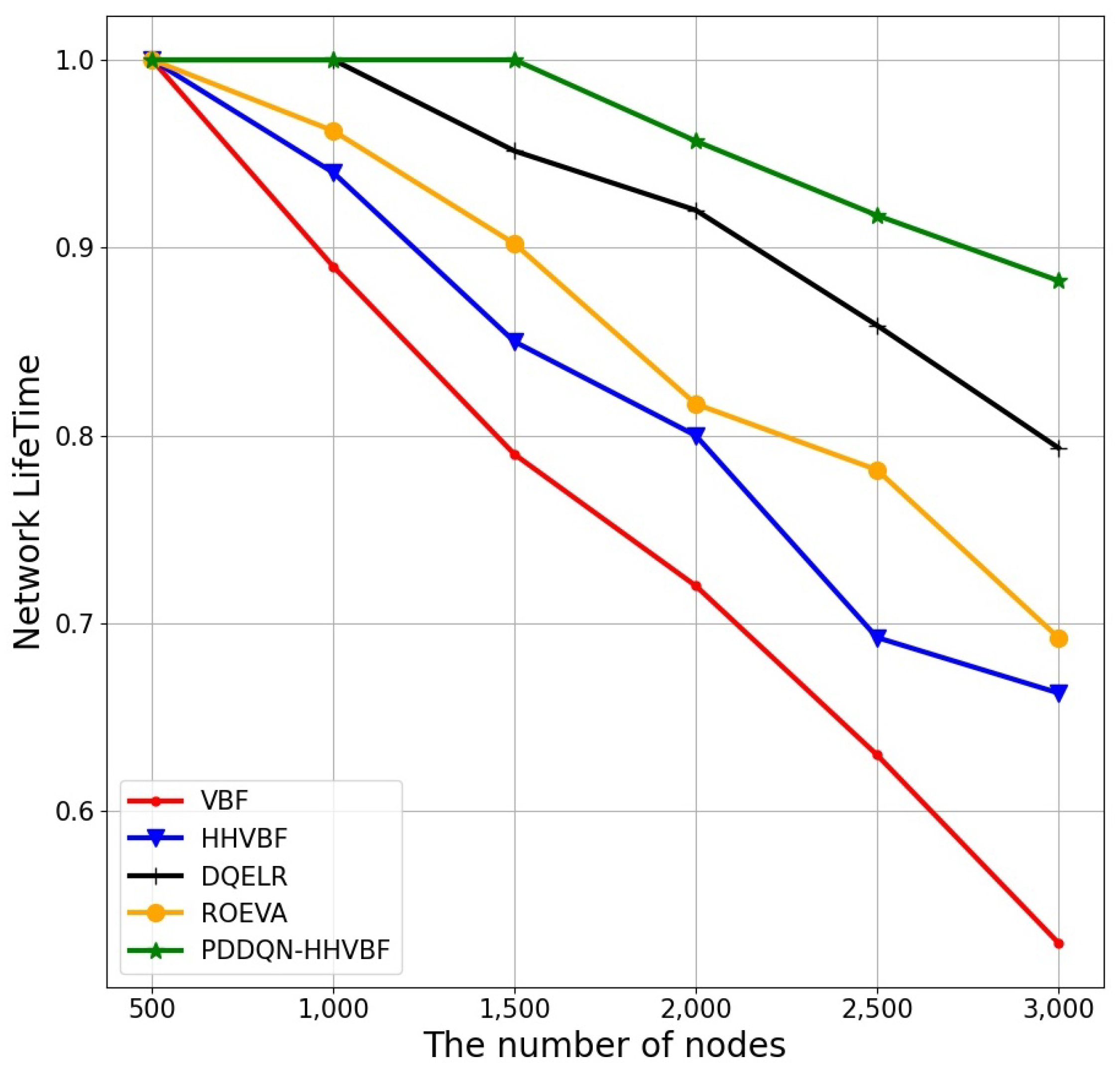
As shown in Figure 19, with the increase of the number of nodes, the network lifetime of the VBF protocol, HHVBF protocol and ROEVA protocol without considering the residual energy of nodes are shorter than the DQELR protocol and the PDDQN-HHVBF protocol. The considering residual energy of nodes protocols will use candidate relay nodes in a load-balanced manner. The PDDQN-HHVBF protocol has a better network lifetime than the DQELR protocol when the number of nodes increases. This is since the protocol proposed in this paper is transmitted in a short distance, and thus the probability of collision of data packets transmitted in a short distance is small. Therefore, the energy consumption of nodes is less, thereby the network lifetime is longer. Otherwise, the PDDQN-HHVBF use “Store-Carry-Forward” mechanism to let the AUV find the relay nodes which will have more opportunities to delivery data packets to next relay node. In this way, it will save more energy of AUV and relay nodes.
Finally, we comprehensively reflect the PDDQN-HHVBF protocol results of the nodes movement speed of 0–3 m/s with 1000 nodes Table 2, and the nodes movement speed of 1 m/s with 500–3000 nodes in the following table in Table 3.

6. Conclusions

In this paper, a routing protocol named PDDQN-HHVBF (Empirical Priority DDQN to Improve Hop-by-Hop Vector-Based Forward) protocol is proposed for M-UWSNs.The proposed protocol finds the optimal relay node to achieve energy saving, reliable data packet transmission and extend network lifetime. In order to reduce packets collision in large-scale M-UWSNs, the protocol uni-cast the packets with short propagation distance to the selected relay nodes calculated by convergent DDQN algorithm based on empirical priority, which converges quickly than DQELR about 30%. In addtion, the proposed protocol select the optimal nodes, with max Q value of all candidate relay nodes, to forward. The optimal relay nodes with higher residual energy, shorter distance for transmission and more candidate relay nodes to forward have make higher PDR, lower energy consumed and longer M-UWSNs lifetime. Finally, the “Store-Carry-Forward” mechanism used in AUV can effectively reduce the energy consumed of AUV, and it alsO can progress the PDR of M-UWSNs. The experimental results show that the performance of the PDDQN-HHVBF protocol in PDR, energy tax, and lifetime are better than that of the relevant comparative protocols. However, in order to improve the reliability of data transmission and reduce the energy consumption, the PDDQN-HHVBF exchanges Q values for many times, so the protocol has a relatively long delay compared DQELR and ROEVA. In the future work, we will consider to reduce the delay of the proposed protocol by designing a MAC (Medium Access Control) protocol that is consistent with this routing protocol.

Author Contributions

Methodology, J.B. and Y.L.; Formal analysis, Y.C.; Investigation, Y.L.; Resources, Y.C.; Data curation, Y.L.; Writing—original draft, J.B.; Writing—review & editing, J.B.; Supervision, Y.L.; Funding acquisition, Y.C. All authors have read and agreed to the published version of the manuscript.

Funding

This work was supported in part by the following projects: the National Natural Science Foundation of China through the Grants 61861014, Doctor start-up fund (BS2021025), the Guangxi Nature Science Fund (2015GXNSFAA139298, 2016GXNSFAA380226), Guangxi University high level innovation team and outstanding scholar program, Guangxi Science and Technology Project (AC16380094, AA17204086, 1598008-29), Guangxi Nature Science Fund Key Project (2016GXNSFDA380031), and Guangxi University Science Research Project (ZD 2014146), Natural Science Foundation of Guangxi Province of China (2020GXNSFAA159090).

Data Availability Statement

Data available on request from the authors.

Acknowledgments

The authors would like to thank the anonymous reviewers for their constructive comments, which greatly helped improve this paper.

Conflicts of Interest

The authors declare no conflict of interest.

References

  1. Zhang, Y.; Zhang, Z.; Chen, L.; Wang, X. Reinforcement Learning-Based Opportunistic Routing Protocol for Underwater Acoustic Sensor Networks. IEEE Trans. Veh. Technol. 2021, 70, 2756–2770. [Google Scholar] [CrossRef]
  2. Jiang, P.; Wang, X.; Jiang, L. Node Deployment Algorithm Based on Connected Tree for Underwater Sensor Networks. Sensors 2015, 15, 16763–16785. [Google Scholar] [CrossRef] [PubMed] [Green Version]
  3. Su, Y.; Fan, R.; Fu, X.; Jin, Z. DQELR: An Adaptive Deep Q-Network-Based Energy- and Latency-Aware Routing Protocol Design for Underwater Acoustic Sensor Networks. IEEE Access 2019, 7, 9091–9104. [Google Scholar] [CrossRef]
  4. Ali, G.; Ali, T.; Hassan, I.U.; Shaf, A.; Irfan, M.; Nowakowski, G.; Kielkowicz, K.; Glowacz, A.; Alqhtani, S.M. A Novel Routing Protocol Based on Elliptical Shaped Movement of Autonomous Underwater Vehicles in Data Gathering Process for Underwater Wireless Sensor Network. Sensors 2022, 22, 5269. [Google Scholar] [CrossRef] [PubMed]
  5. Cui, Y.; Wang, J.; Sun, H.; Jiang, H.; Yang, K.; Zhang, J. Gridless Underdetermined DOA Estimation of Wideband LFM Signals With Unknown Amplitude Distortion Based on Fractional Fourier Transform. IEEE Internet Things J. 2020, 7, 11612–11625. [Google Scholar] [CrossRef]
  6. Jiang, H.; Zhang, Z.; Wu, L.; Dang, J.; Gui, G. A 3-D Non-Stationary Wideband Geometry-Based Channel Model for MIMO Vehicle-to-Vehicle Communications in Tunnel Environments. IEEE Trans. Veh. Technol. 2019, 68, 6257–6271. [Google Scholar] [CrossRef]
  7. Jiang, H.; Xiong, B.; Zhang, Z.; Zhang, J.; Zhang, H.; Dang, J.; Wu, L. Novel statistical wideband MIMO V2V channel modeling using unitary matrix transformation algorithm. IEEE Trans. Wirel. Commun. 2021, 20, 4947–4961. [Google Scholar] [CrossRef]
  8. Jiang, H.; Ying, W.; Zhou, J.; Shao, G. A 3D Wideband Two-Cluster Channel Model for Massive MIMO Vehicle-to-Vehicle Communications in Semi-Ellipsoid Environments. IEEE Access 2020, 8, 23594–23600. [Google Scholar] [CrossRef]
  9. Islam, K.Y.; Ahmad, I.; Habibi, D.; Waqar, A. A survey on energy efficiency in underwater wireless communications. J. Netw. Comput. Appl. 2022, 198, 103295. [Google Scholar] [CrossRef]
  10. Mhemed, R.; Comeau, F.; Phillips, W.; Aslam, N. Void avoidance opportunistic routing protocol for underwater wireless sensor networks. Sensors 2021, 21, 1942. [Google Scholar] [CrossRef]
  11. Wang, X.; Qin, D.; Zhao, M.; Guo, R.; Berhane, T.M. UWSNs positioning technology based on iterative optimization and data position correction. EURASIP J. Wirel. Commun. Netw. 2020, 2020, 158. [Google Scholar] [CrossRef]
  12. Xie, P.; Cui, J.-H.; Lao, L. VBF: Vector-based forwarding protocol for underwater sensor networks. In NETWORKING 2006. Networking Technologies, Services, and Protocols; Performance of Computer and Communication Networks; Mobile and Wireless Communications Systems; Boavida, F., Plagemann, T., Stiller, B., Westphal, C., Monteiro, E., Eds.; Springer: Berlin, Germany, 2006; pp. 1216–1221. [Google Scholar]
  13. Nicolaou, N.; See, A.; Xie, P.; Cui, J.; Maggiorini, D. Improving the robustness of location-based routing for underwater sensor networks. In Proceedings of the IEEE OCEANS 2007—Europe, Aberdeen, UK, 18–21 June 2007; pp. 1–6. [Google Scholar] [CrossRef]
  14. Yu, H.; Yao, N.; Liu, J. An adaptive routing protocol in underwater sparse acoustic sensor networks. Ad Hoc Netw. 2015, 34, 121–143. [Google Scholar] [CrossRef]
  15. Yan, H.; Shi, Z.J.; Cui, J.H. DBR: Depth-based routing for underwater sensor networks. In International Conference on Research in Networking; Springer: Berlin/Heidelberg, Germany, 2008; pp. 72–86. [Google Scholar] [CrossRef] [Green Version]
  16. Mohammadi, R.; Javidan, R.; Jalili, A. Fuzzy depth based routing protocol for underwater acoustic wireless sensor networks. J. Telecommun. Electron. Comput. Eng. (JTEC) 2015, 7, 81–86. [Google Scholar]
  17. Diao, B.; Xu, Y.; An, Z.; Wang, F.; Li, C. Improving both energy and time efficiency of depth-based routing for underwater sensor networks. Int. J. Distrib. Sens. Netw. 2015, 2015, 1–9. [Google Scholar] [CrossRef]
  18. Liang, Q.; Zhang, B.; Zhao, C.; Pi, Y. TDoA for passive localization: Underwater versus terrestrial environment. IEEE Trans. Parallel Distrib. Syst. 2013, 24, 2100–2108. [Google Scholar] [CrossRef]
  19. Noh, Y.; Lee, U.; Wang, P.; Choi, B.S.C.; Gerla, M. VAPR: Void-aware pressure routing for underwater sensor networks. IEEE Trans. Mobile Comput. 2013, 12, 895–908. [Google Scholar] [CrossRef]
  20. Ghoreyshi, S.M.; Shahrabi, A.; Boutaleb, T. An inherently void avoidance routing protocol for underwater sensor networks. In Proceedings of the International Symposium on Wireless Communication Systems, Brussels, Belgium, 25–28 August 2015; pp. 361–365. [Google Scholar] [CrossRef]
  21. Ghoreyshi, S.M.; Shahrabi, A.; Boutaleb, T. A novel cooperative opportunistic routing scheme for underwater sensor networks. Sensors 2016, 16, 297. [Google Scholar] [CrossRef]
  22. Jin, Z.; Duan, C.; Yang, Q.; Su, Y. Q-learning-based opportunistic routing with an on-site architecture in UASNs. Ad Hoc Netw. 2021, 119, 102553. [Google Scholar] [CrossRef]
  23. Lin, X.; Tang, Y.; Lei, X.; Xia, J.; Zhou, Q.F.; Wu, H.; Fan, L. MARL-based distributed cache placement for wireless networks. IEEE Access 2019, 7, 62606–62615. [Google Scholar] [CrossRef]
  24. Hu, T.; Fei, Y. QELAR: A machine-learning-based adaptive routing protocol for energy-efficient and lifetime-extended underwater sensor networks. IEEE Trans. Mobile Comput. 2010, 9, 796–809. [Google Scholar] [CrossRef]
  25. Hu, T.; Fei, Y. MURAO: A multi-level routing protocol for acousticoptical hybrid underwater wireless sensor networks. In Proceedings of the 9th Annual IEEE Communications Society Conference on Sensor, Mesh and Ad Hoc Communications and Networks, Seoul, South Korea, 18–21 June 2012; pp. 218–226. [Google Scholar] [CrossRef]
  26. Jin, Z.; Zhao, Q.; Su, Y. RCAR: A reinforcement-learning-based routing protocol for congestion-avoided underwater acoustic sensor networks. IEEE Sens. J. 2019, 19, 10881–10891. [Google Scholar] [CrossRef]
  27. Zhou, Y.; Cao, T.; Xiang, W. QLFR: A Q-Learning-Based Localization-Free Routing Protocol for Underwater Sensor Networks. In Proceedings of the 2019 IEEE Global Communications Conference (GLOBECOM), Waikoloa, HI, USA, 9–13 December 2019; pp. 1–6. [Google Scholar] [CrossRef]
  28. Chen, Y.; Zheng, K.; Fang, X.; Wan, L.; Xu, X. QMCR: A Q-learning-based multi-hop cooperative routing protocol for underwater acoustic sensor networks. China Commun. 2021, 18, 224–236. [Google Scholar] [CrossRef]
  29. Zhu, R.; Jiang, Q.; Huang, X.; Li, D.; Yang, Q. A reinforcement-learning-based opportunistic routing protocol for energy-efficient and Void-Avoided UASNs. IEEE Sens. J. 2022, 22, 13589–13601. [Google Scholar] [CrossRef]
  30. Mnih, V.; Kavukcuoglu, K.; Silver, D.; Rusu, A.A.; Veness, J.; Bellemare, M.G.; Graves, A.; Riedmiller, M.; Fidjeland, A.K.; Ostrovski, G. Human-level control through deep reinforcement learning. Nature 2015, 518, 529–533. [Google Scholar] [CrossRef] [PubMed]
  31. Lin, L.J. Self-improving reactive agents based on reinforcement learning, planning and teaching. Mach. Learn. 1992, 8, 293–321. [Google Scholar] [CrossRef]
  32. Van Hasselt, H.; Guez, A.; Silver, D. Deep reinforcement learning with double Q-learning. In Proceedings of the AAAI Conference on Artificial Intelligence, Phoenix, AZ, USA, 12–17 February 2016; Volume 30. [Google Scholar] [CrossRef]
Figure 1. The schematic diagram of M-UWSNs.
Electronics 11 04031 g001
Figure 2. The schematic diagram of MDP.
Electronics 11 04031 g002
Figure 3. The schematic diagram of PDDQN-HHVBF pipeline.
Electronics 11 04031 g003
Figure 4. The schematic diagram of virtual pipelines in M-UWSNs.
Electronics 11 04031 g004
Figure 5. The schematic diagram of candidate relay nodes.
Electronics 11 04031 g005
Figure 6. The schematic diagram of the current network.
Electronics 11 04031 g006
Figure 7. The schematic diagram of the target network.
Electronics 11 04031 g007
Figure 8. The schematic diagram of SumTree.
Electronics 11 04031 g008
Figure 9. The schematic diagram of the Q value of pre-forwarding node request.
Electronics 11 04031 g009
Figure 10. The schematic diagram of AUV “Store-Carry-Forward” mechanism.
Electronics 11 04031 g010
Figure 11. Comparison of the loss function of DQELR and PDDQN-HHVBF protocol with the number of iterations.
Electronics 11 04031 g011
Figure 12. The PDR of VBF, HHVBF, DQELR, ROEVA, and PDDQN-HHVBF protocol in different speed of nodes.
Electronics 11 04031 g012
Figure 13. The energy tax of VBF, HHVBF, DQELR, ROEVA, and PDDQN-HHVBF protocol in different speed of nodes.
Electronics 11 04031 g013
Figure 14. The end-to-end delay of VBF, HHVBF, DQELR, ROEVA, and PDDQN-HHVBF protocol in different speed of nodes.
Electronics 11 04031 g014
Figure 15. The AUV energy consumed of “Store-Carry-Forward” and “Forward-Confirm” in different speed of nodes.
Electronics 11 04031 g015
Figure 16. The PDR of VBF, HHVBF, DQELR, ROEVA, and PDDQN-HHVBF protocol in different number of network nodes.
Electronics 11 04031 g016
Figure 17. The energy tax of VBF, HHVBF, DQELR, ROEVA, and PDDQN-HHVBF protocol in different number of network nodes.
Electronics 11 04031 g017
Figure 18. The end-to-end delay of VBF, HHVBF, DQELR, ROEVA, and PDDQN-HHVBF protocol in different number of network nodes.
Electronics 11 04031 g018
Figure 19. The network lifetime of VBF, HHVBF, DQELR, ROEVA, and PDDQN-HHVBF protocol in different number of network nodes.
Electronics 11 04031 g019
Table 1. Experimental parameters.
Experimental ParamentsValues
Transmission range100 m
Initial energy10,000 J
Transmission power10 W
Receiving power1 W
Control packet power0.2 W
Number of nodes500–3000
AUV speed10 m/s
Node random movement speed0–3 m /s
Packet size20 Bytes
Transmission rate1 pkt/s
Batch sample size256
Table 2. Experimental results of different nodes speed with 1000 nodes.
Network Performance Metrics0 m/s0.5 m/s1 m/s1.5 m/s2 m/s2.5 m/s3 m/s
PDR (%)10010092.584.676.472.461.2
energy tax (J)355.2395.4427.3496.4558.2608.4687.9
end-to-end delay (s)9.489.579.699.759.9310.0310.23
Table 3. Experimental results of different number of node with 1 m/s.
Network Performance Metrics500 Nodes1000 Nodes1500 Nodes2000 Nodes2500 Nodes3000 Nodes
PDR (%)58.292.594.8100100100
energy tax (J)750.4355.6255.2140.4178.4218.4
end-to-end delay (s)9.619.699.8810.1410.3010.43
lifetime (%)1110.950.910.88
Publisher’s Note: MDPI stays neutral with regard to jurisdictional claims in published maps and institutional affiliations.