Abstract
Microgrids are a part of the power system that consists of one or more units of distributed generation and are expected to remain in operation after being disconnected from the system. Since they rely on overlying networks, frequency control is very important for network-independent operation. Some of the most common problems in independently operating microgrids are frequency sustainability and its fluctuations. The main purpose of this study is to control the frequency of a microgrid in island mode in different scenarios. The objective function is defined based on time and changes in the system frequency. Thus, the variable parameters of the PID controller are transformed into an optimization problem and are solved through the hybrid PSO-GSA algorithm. The study considers four scenarios: (a) a microgrid dynamic model and optimal PID controller coefficients; (b) variable velocity disturbance applied to the studied system in order to observe power changes and the microgrid frequency; (c) stepped load changes applied to the studied system; and (d) the proposed methods on the standard test function. Simulations under different operating conditions are performed, indicating improvements in the stability of microgrid frequency fluctuations by means of the proposed control method.
1. Introduction
A microgrid usually consists of a set of distributed generation sources, an energy storage system, and local loads. It can be connected to a network or operate in island mode, and it has many benefits for both consumers and power generation companies. From the perspective of the consumer, microgrids are able to simultaneously provide electricity and heat [1], increase reliability [2], reduce greenhouse gas emissions [3], improve the quality of power, and reduce the costs of consumption [4,5]. As for electricity companies [6], the use of microgrids has the potential to reduce consumption demand and, in turn, the facilities necessary for the development of transmission lines [7]. In addition, they eliminate peak consumption points [8], which results in reduced network losses [9]. By definition, distributed generation (DG) includes electrical power generation units with a capacity of less than 10 MW which have distribution feeders or common levels connected to the network. Depending on the capacity and location of the source installation, connecting DG to a distribution network can have a positive or negative effect on its performance [10]. On the other hand, DG causes the power flow in distribution networks to change. Therefore, a main network with the presence of DG is not optimal for reducing losses; there needs to be a proper control in the network, so that the distribution network operates at optimal cost and with increased reliability [11]. In other words, with the advent of DG resources, several problems have appeared, such as maintaining and protecting resources [12], the way in which these resources are involved in setting the basic parameters of the network (such as frequency and voltage [13,14]), and the method for power exchange between the global network and distributed generation sources [15]. In 1998, to solve these problems and consider these resources and local loads as integrated, the concept of micro-grid was introduced in modern power systems [16]. Accordingly, microgrids are small power networks composed of several distributed generation sources and local loads. They are usually connected to the global network, and they are isolated from the main network in the event of heavy disturbances. They can also feed sensitive loads [17].
Real power systems face a variety of uncertainties, which are caused by changes in load [18], system modeling errors, and structural changes [19]. Therefore, classical controllers with constant interest are not suitable for solving the Load Frequency Control (LFC) problem [20,21,22]. In order to cover these limitations, a flexible controller is required. So far, various controllers for LFC have been presented. Among these controllers, the PID controller has generally attracted more attention than the others [23,24]. The controller’s interests are determined at the nominal working points. The controller’s interests are determined through the classical method [25]. In other words, increasing the number of microgrids changes the fundamental rules of power systems and causes the production resources to be distributed throughout them [26]. This leads to an increase in the complexity and nonlinearity of power networks, so the proper response of classical controllers can no longer be observed. PD-PI controllers are widely used in power systems because they have a simple and cost-effective structure, and, in power systems, they are more reliable than any other controller. However, the problem with these controllers is that their control coefficients are set up for a single time and placed in the system according to the linear conditions and operating points of the system. If the nominal working conditions or the system’s linear conditions change due to turbulence, the values considered for these controllers are not optimal, and they do not have the same response. A possible solution is to update and optimize the control coefficients according to the incident changes in the system [27]. The development of power networks due to increased energy demand and technical issues has caused today’s power systems to activate within their own boundaries. This has led to more sustainability in said systems. In order to increase stability and overcome the problems with classical controllers in different working conditions, fuzzy controllers have been used as resistant stabilizers to modulate small signal fluctuations [28,29,30]. Ref. [31] used a new method for controlling the microgrid frequency with a drop control in a photovoltaic converter and battery, in which a low-voltage microgrid is considered to be multiple virtual microgrids. This strategy has improved the finetuning of the microgrid frequency. In [32], the torque and frequency power drop control are applied to the converter of a wind turbine’s doubly fed induction generator. In [33], the optimal self-healing strategy for microgrid islanding is formulated as an optimization problem. A reconstruction framework and solutions for power outages in microgrids are provided in [34]. A regulatory management of renewable resources based on controllers is discussed in [35]. In [36], the optimization method is used by planning to maximize profit and minimize operation cost. In [37], a microgrid strategy is proposed using a self-healing agent that operates based on a centralized or decentralized approach. Small-signal stability analysis is performed to evaluate the stability of microgrids to avoid any instability problems. Ref. [38] employed the Frequency Containment Reserves (FCR) technique with the goal of improving the economic profitability of microgrids. The primary loop control of the frequency (drop control) was established in order to control the microgrid frequency and reduce pollution and the cost of power generation. Drop control cannot properly control the microgrid frequency under heavy load variations, and it is not properly efficient in island mode. To control the frequency of an islanded microgrid, a secondary control loop is generally used for reducing frequency fluctuations under severe load variations [39]. LFC is one of the most important issues in microgrids. LFC has been investigated due to the relatively low inertia of these systems [40]. In [41], a multivariate unconstrained pattern search method for the optimization of digital PID controllers applied in an isolated forward converter is studied. Conventional digital PID controllers are considered to be designed based on digital redesign and direct digitalization, adjusted by one of the multivariate name search pattern search methods called the Hooke–Jeeves (H-J) search method; with an excellent performance, output voltage regulation can be ensured. Droop control techniques are currently used to coordinate DG units in a microgrid. However, this method has its own advantage. It is used for a nonlinear analysis to predict the qualitative behavior of the system with the aim of reducing the differential equations [42,43]. In [44], an isolated non-DC–DC boost converter is designed. This converter is designed by adding to networks and VMCs. In [45], frequency control in hybrid distributed power systems via a type-2 fuzzy PID controller studied. A new Internet of Things-based optimization scheme of a residential demand side management system was tested [46]. In addition, in [47], the Optimized Robust Controller Design based on the CPSOGSA Optimization Algorithm and H2/H∞ Weights Distribution Method for Load Frequency Control of Microgrids was investigated.
This paper investigates the communication aspects of multiple markets with primary control (centralized and decentralized) loops. Designing a controller usually consists of three steps: first, choosing a control rule that contains changeable parameters; second, choosing a method to set these parameters; third, analysis of system convergence properties. The PID controller and coordination algorithm and parameter optimization are used due to the advantages of robustness against system parameter uncertainties, faster convergence speed when approaching the reference point, adaptability to system uncertainties, and the ability to prove stability. However, so far there have been few research results that use the combination method to design a controller for different coordinations. This still remains an open and challenging issue and has motivated us to write this paper. Therefore, one of the most important goals of reducing the effect of disturbances on the system and maintaining the quality of power and frequency is to improve the dynamic performance of the system in microgrids and the accuracy of power distribution between units in a limited time. In addition, an optimization method based on the PSO-GSA optimization algorithm is presented to achieve better and more accurate results. The rest of the article is as follows: Section 2 studies an example of independent microgrid modeling. In Section 3, the proposed PSO-GSA algorithm and its hybrid are discussed. In Section 4, the intelligent PID controller is designed to optimally adjust the parameters. Section 5 introduces a new method for damping and sustainability frequency fluctuations in the microgrid (while separated from the main grid) based on the PID controller and a hybrid PSO-GSA algorithm. The following aspects are studied: (a) the microgrid dynamic model and PID controller; (b) Calculation of optimal controller coefficients; (c) PID and hybrid PSO-GSA coordination; (d) Variable velocity disturbance; (e) Power and frequency changes; (f) Stepped load changes applied to the system; and (g) Effect of the proposed methods on the standard test function. Finally, Section 6 presents the conclusions. The results show the appropriate efficiency of the proposed controller in quenching fluctuations in a shorter period of time.
2. Microgrid Modeling
Nowadays, the expansion of transmission and distribution networks can pose challenges to power systems, even though they have advantages such as increased network reliability and improved stability. Among these challenges are the non-economic transmission of electrical energy from power plants to remote and impenetrable areas, the increase in transmission and distribution losses, and the increased complexity of the network’s protection system due to its widespread use. All of these have led to the widespread use of DG resources in recent years, whose main principle is the production of electrical energy at the place of consumption. The concept of the microgrid is a result of several DG resources placed together [48]. Microgrids include DG resources and local loads that can feed the loads both disconnected from and connected to the global network. The overall structure of a microgrid is shown in Figure 1.
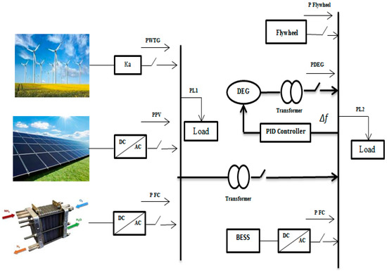
Figure 1.
General structure of a microgrid.
The following resources are included: photovoltaic generator (PV), diesel engine generator (DEG), wind turbine generator (WTG), fuel cell (FC), battery energy storage system (BESS), flywheel energy storage system (FESS), and aqua electrolyzer (AE). The microgrid and the global network communicate with each other at the PCC. The micro-resources used in these networks are interconnected with the help of electronic elements. In fact, in these microgrids, AC or DC elements are used as converters or the like [49].
3. PSO-GSA Algorithm
3.1. Gravitational Search Algorithm (GSA)
The GSA is a collective and non-memory intelligence algorithm [50,51]. This optimization algorithm has been designed by modeling the rules and the movement of factors in an artificial system in discrete times at which the system space is the same as the problem definition range. According to the law of gravity, each mass perceives the location and condition of other masses. In this algorithm, the mass of the agents is provided according to the objective function [51]. In a system with mass n, the position of each mass is a point in space, which is the answer to the problem. The position of mass i is shown with in Equation (1):
where n is the dimension of the problem, and is the dimension d of the mass i. This system, with mass i at time t and in the direction d, is powered by a force with a value. The size of this force is obtained via Equation (2):
where is the active gravitational mass of j, and is the inactive gravitational mass of j, both of which are considered the same and equal to M in the mentioned algorithm; G(t) is the gravitational constant at time t; and is the distance between the two masses i and j, which is also a very small number. The gravitational constant is an appropriate parameter for controlling the search and productivity capabilities, which is expressed by Equation (3):
where α and G0 are the control coefficients of the algorithm, and T indicates the system’s lifetime. The force on mass i in the direction of dimension t at time t is equal to the sum of all the forces that the other masses of the system exert on this mass. In this equation, is a random number with uniform distribution in the interval (1.0), which is considered for the sake of randomness [51]:
Furthermore, each of the masses has a specific speed and acceleration, each of which is shown in Equations (5) and (6), respectively. According to Newton’s second law, each mass is accelerated in the direction of dimension d, which is proportional to the force on the mass in that dimension, divided by its inertia mass, as stated in Equation (4). On the other hand, the velocity of each factor at time t is equal to the sum of the coefficients of the current velocity and the acceleration of the factor, as expressed in Equations (5) and (6):
When the acceleration and velocity of each mass are calculated, the new position of agent i in the dimension d is calculated according to Equation (7):
New situations are considered as the locations of new masses within the search space, where the weight of new masses is normalized via Equations (8) and (9):
where represents the degree of maturity of the mass of agent i at time t, and worst(t) and best(t), respectively, indicate the suitability of the worst and the best factors of population in time, whose size can be calculated using Equations (10) and (11):
3.2. Particle Swarm Optimization (PSO)
In this section, the particle swarm optimization algorithm is briefly outlined. For more information on this topic, the readers are advised to refer to [52,53]. In the topology of the particle swarm optimization algorithm in the D-dimensional search space, the best personal position of particle i is indicated by , and the best position of the group is represented by . The relationship between the velocity and the motion of particle i at a given moment or the repetition of the dimension are obtained in the form of Equations (12) and (13):
In Equation (12), ω is the inertia coefficient of the particle, and c1 and c2 are Hook spring coefficients or acceleration coefficients, which are usually set to 2. To randomize the nature of the velocity, the coefficients c1 and c2 are multiplied by the random numbers rand1 and rand2. Usually, in the implementation of the PSO, the value of ω decreases linearly from one to values close to zero. The inertia coefficient ω is generally determined according to Equation (14):
where is the maximum repetition number, is the current repetition number, and and are the maximum and minimum values of the inertial coefficients, which are set at 0.9 and 0.3, respectively. is the magnitude of the velocity of particle i in each dimension of the D-dimensional search space, which is limited to the interval [−], so that the particle’s possibility of leaving the search space is reduced. The value of is usually chosen so that x = k, where 0.1 < k < 1, so that specifies the length of the search.
4. Hybrid PSO-GSA Algorithm
The aim of combining different methods is to achieve better results than each technique would obtain on its own. The particle swarm optimization and gravitational search algorithms are well suited to be combined, through which a primary randomized population, generational upgrading, and the generation of new solutions can be achieved. Figure 2 shows such a combination with a primary population [54]. If the problem is N-dimensional, then the hybrid algorithm has 4N members, which are generated in a completely random way. 4N members are arranged by competency, and 2N upper members are considered as masses in the gravitational search algorithm. Additionally, a new 2N member population is created. Particle swarm optimization is applied to the 2N lower members. In applying the particle swarm optimization mechanism, the new population created by the gravitational search algorithm is used as a regulator. The best member of this new population is used as the , and each corresponding member is used as a neighborhood or t in Equation (12). The population generated by applying particle swarm optimization and the population created by the gravitation search algorithm are merged and integrated, and the new 4N members are arranged by competency. The previous process is then repeated until convergence is achieved. The mechanism of particle swarm optimization is applied to the 2N lower members as particles. In applying the particle swarm optimization mechanism, the new population created by the gravitational search algorithm is used as a regulator.
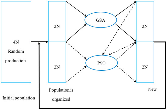
Figure 2.
Hybrid PSO-GSA method.
In the proposed controller (according to Figure 3), in the first stage, the changes in power sources, load, and frequency of the microgrid are evaluated and measured. Then, in the next step, the output of the system (frequency changes) and the appropriate controller signals are applied according to the law. The relationships governing the behavior of the controller are described using relationships (15) to (21).
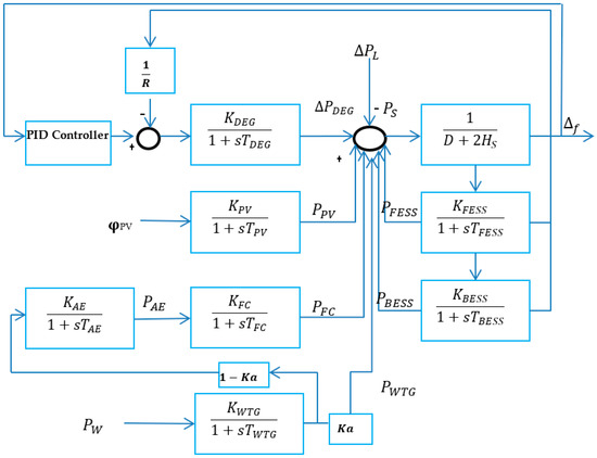
Figure 3.
Studied system.
Function: which should be minimized; N1: Lower limit; N2: Upper limit; : Control limit; is the numerical coefficients resulting from solving the problem (by minimizing J). The index introduced in relation (21) is used to compare control methods in the simulation section.
5. Case Study
The studied system is shown in Figure 3, i.e., the main grid system containing conventional DEG, solar panels, wind turbines, fuel cells, and battery energy storage systems. The hierarchical control structure of the microgrid includes WTG, FC, BESS, PV, DEG, FESS, and AE.
The dynamic model of a wind turbine for the analysis of a small signal is expressed by relation, and its characteristic function is expressed as follows:
where and are the gain coefficient and the time constant, Ka is a numerical coefficient that expresses the wind turbine power percentage, represents the changes in the electrical output of the wind turbine, and expresses changes in the power obtained from the wind.
The following is the dynamic PV model:
where and are the PV gain coefficient and the time constant, are the changes in the PV electrical output, and are changes are in solar radiation intensity.
Diesel generators play a major role in hybrid microgrids; as the load increases, they are responsible for providing part of the capacity needed to reach equilibrium. The dynamic model of a diesel generator is expressed via small-signal analysis as follows:
where and are the gain coefficient and the time constant of the diesel generator, is the speed drop coefficient, and represents changes in the DEG power.
The dynamic model of the fuel cell, electrolyzer, battery, and flywheel is described below:
where , , , , , , , and are the interest rate and time constant of the diesel generator, electrolyzer, battery, and flywheel, respectively; is the speed drop coefficient, represents changes in the fuel cell power, and expresses changes in the power.
The parameters of the microgrid’s power sources are shown in Table 1, and the nominal power of the microgrid is shown in Table 2. The proposed algorithm is applied to the studied system and used to optimize the controller parameters. Table 3 shows the initial parameters for the PSO-GSA. The results for the studied system are shown in Table 4, and Figure 4 depicts the proposed algorithm in the sample system.

Table 1.
Parameters of the microgrid’s power sources [55,56].
Table 2.
Nominal microgrid power [55,56].
Table 3.
Initial parameters for PSO-GSA.
Table 4.
Optimized PID parameter results (PSO and PSO-GSA).
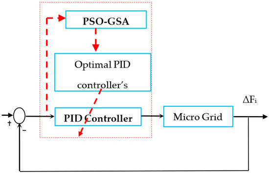
Figure 4.
Proposed algorithm on the system under study.
Figure 5 shows the convergence of the algorithm. As shown in the figure, the proposed hybrid algorithm is optimized at a significant speed to the final value, which indicates its high speed and proper accuracy.
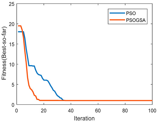
Figure 5.
Convergence of algorithms (PSO–PSOGSA).
Kp, Ki, and Kd parameters are calculated according to the following equation:
where K1, K2, and K3 are the optimized normalized coefficients for the PID controller, and their values are 0.044, 30, and 16.5, respectively. are the nominal values of the parameters, all of which were set to 5 before optimization.
Note that the general solution methodologies based on the combinatorial optimization methods for tunning the PID gains are depicted in Figure A1.
6. Results and Discussion
The studied source includes a fuel cell and a photovoltaic generator, which utilize a higher technology than other conventional DGs. This source is also connected to the distribution system by an inverter. Since the production of electrical energy in a low-velocity fuel cell is carried out in DC and at low voltage, the accessories of the fuel processor unit (to produce hydrogen) and a conventional DC–DC incremental converter are required to increase the DC link voltage. To evaluate the proposed method in the modeled space, as well as the way to improve the dynamics of the system, various simulations were run. By applying a control signal to the sources, frequency disturbances were subsequently reduced due to potential changes in the microgrid. In this section, noise related to variable wind speed was applied, which ranged from 0.2 to −0.2 pu (Figure 6). Figure 7 shows the frequency changes of the microgrid system with and without a PID controller. It can be observed that, to some extent, the PID controller achieved good results regarding stability and the attenuation of frequency changes. For optimal results, the hybrid PSO-GSA algorithm was used. It was observed that, in this simulation, the proposed smart controller had a more favorable performance than that of the particle swarm controller (Figure 8). The power of the wind turbines, fuel cells, photovoltaic generators, batteries, flywheels, and diesel generators before and after the disturbances are shown in Figure 9, Figure 10, Figure 11, Figure 12, Figure 13 and Figure 14. Apart from the photovoltaic power, other sources were affected by disturbances. To evaluate the performance of the proposed control method, several different disturbances were applied to the test microgrid, and the system’s response was compared to the results obtained with the algorithms. As mentioned in the previous section, there are resources in microgrids such as solar panels and wind turbines whose power is rather volatile.
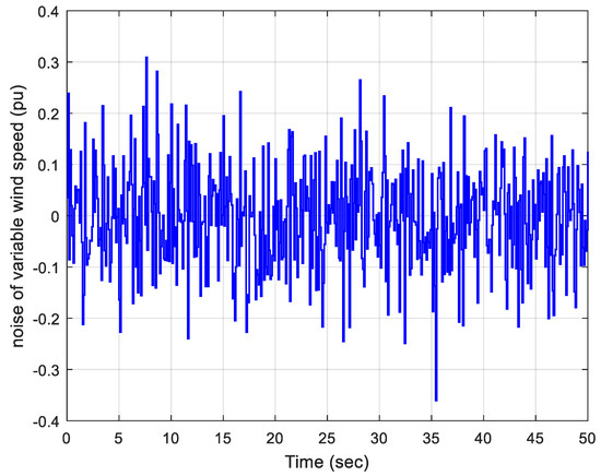
Figure 6.
Variable velocity disturbances applied to the studied system.
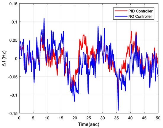
Figure 7.
Frequency changes with and without a PID controller.
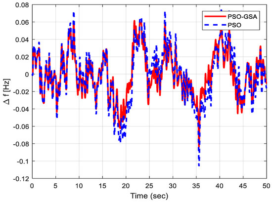
Figure 8.
Frequency changes with PSO and PSO-GSA.
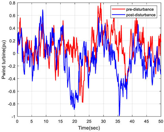
Figure 9.
Wind turbine power (pre- and post-disturbance).
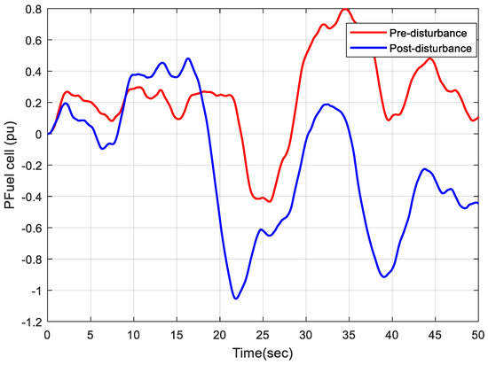
Figure 10.
Fuel cell power (pre- and post-disturbance).
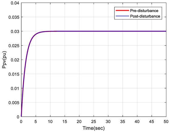
Figure 11.
Photovoltaic power (pre- and post-disturbance).
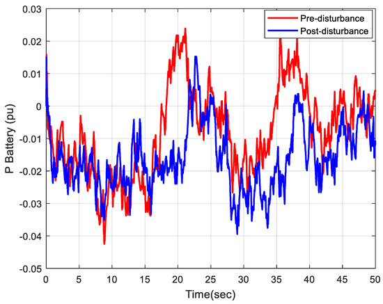
Figure 12.
Battery power (pre- and post-disturbance).
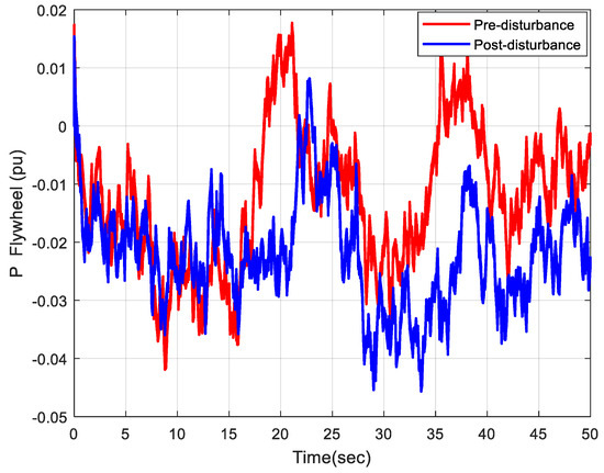
Figure 13.
Flywheel power (pre- and post-disturbance).
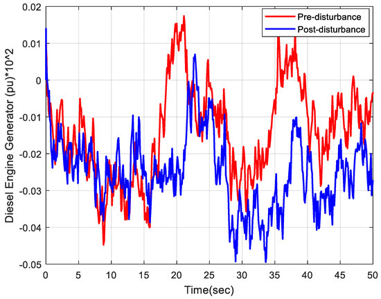
Figure 14.
Diesel generator power (pre- and post-disturbance).
In this section, the stepped load was first applied to the system (Figure 15), and the standard PSO and PSO-GSA algorithms were then executed. The results of the frequency variations are shown in Figure 16. The figure shows that, with the stepped variations of load, the combined algorithm yields less overshot and undershot.
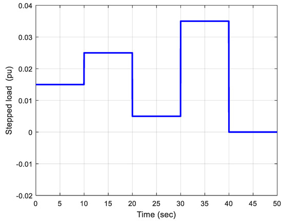
Figure 15.
Stepped load changes applied to the studied system.
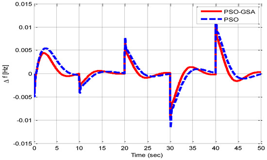
Figure 16.
Frequency changes of the studied system per stepped load.
The performance of the algorithm on the standard test function was evaluated in order to determine its standard deviation. For a better assessment of the effectiveness of the proposed method, a larger range in comparison with other methods was selected. This function is defined as follows:
For a better comparison, the best coefficients were extracted from other papers, albeit considering the same initial population. Figure 17 shows the distribution of the results obtained from 30 different implementations with the proposed methods. The proximity of the solutions obtained by the algorithm indicates its robustness and high performance. It also shows that the proposed method has a smaller standard deviation.
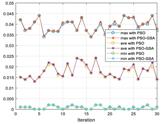
Figure 17.
Best value obtained from 30 different implementations for the standard test function.
Regarding the accuracy of the algorithm with the Sphere function, in this section, the Sphere function is used for the accuracy of the proposed algorithm. The Sphere function acts like a closed circle and the specified value tends to be zero. The formulation of the desired objective function is in the form of Equation (38).
The function in the algorithm is determined instead of the desired objective function, and its goal is to minimize the desired parameter. The results of this function in Figure 18 show that the convergence reaches a zero value.
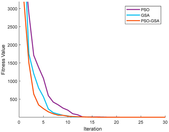
Figure 18.
Algorithm convergence with Sphere objective function.
7. Conclusions
In this paper, a sample microgrid with a PID controller was modeled while using a hybrid PSO-GSA. To better investigate and analyze the proposed controller, various errors were used. The results indicate that the proposed algorithm is more efficient in comparison with particle swarm-based controllers. The optimization algorithm proposed in this paper is novel and has a higher convergence speed compared to PSO algorithms. The proposed method was tested on a case study, and the results show that setting the controller parameters leads to a better frequency response. Therefore, the proposed controller has an optimal performance at adjusting the frequency of the microgrid and achieving the final response after a short transition time with low harmonic distortion.
Author Contributions
Conceptualization, F.Z. and E.A.; methodology, F.Z., E.A. and O.D.M.; software, F.Z. and E.A.; validation, F.Z., E.A., O.D.M., D.A.G.-R. and A.M.-C.; formal analysis, F.Z. and E.A.; investigation, F.Z., E.A. and O.D.M.; resources O.D.M., D.A.G.-R. and A.M.-C.; data curation, D.A.G.-R. and A.M.-C.; writing—original draft preparation, F.Z. and E.A.; writing—review and editing, O.D.M., D.A.G.-R. and A.M.-C.; visualization, F.Z. and E.A.; supervision, O.D.M., D.A.G.-R. and A.M.-C.; project administration, O.D.M.; funding acquisition, O.D.M., D.A.G.-R. and A.M.-C. All authors have read and agreed to the published version of the manuscript.
Funding
This research received no external funding.
Institutional Review Board Statement
Not applicable.
Informed Consent Statement
Not applicable.
Data Availability Statement
No new data were created or analyzed in this study. Data sharing is not applicable to this article.
Conflicts of Interest
The authors declare no conflict of interest.
Appendix A

Figure A1.
Flow diagram of the proposed intelligent tunning algorithm for adjusting the PID gains using combinatorial optimization: (a) Flowchart of PSO algorithm, (b) Flowchart of PSO–GSA algorithm.
References
- Shin, D.-U.; Jeong, C.-H. Energy Savings of Simultaneous Heating and Cooling System According to Indoor Set Temperature Changes in the Comfort Range. Energies 2021, 14, 7691. [Google Scholar] [CrossRef]
- Sandelic, M.; Peyghami, S.; Sangwongwanich, A.; Blaabjerg, F. Reliability aspects in microgrid design and planning: Status and power electronics-induced challenges. Renew. Sustain. Energy Rev. 2022, 159, 112127. [Google Scholar] [CrossRef]
- Hamedi, K.; Sadeghi, S.; Esfandi, S.; Azimian, M.; Golmohamadi, H. Eco-Emission Analysis of Multi-Carrier Microgrid Integrated with Compressed Air and Power-to-Gas Energy Storage Technologies. Sustainability 2021, 13, 4681. [Google Scholar] [CrossRef]
- Yuvaraja, S.; Salam, M.S.A.; Vijayaraja, L.; Kesavan, R.; Dhanasekar, R. A novel PWM scheme for grid-tied inverter in micro-grid with enhanced power quality using silicon cells. Mater. Today Proc. 2021, 46, 4298–4304. [Google Scholar] [CrossRef]
- Wu, M.; Niu, X.; Gao, S.; Wu, J. Power Quality Assessment for AC/DC Hybrid Micro Grid Based on On-Site Measurements. Energy Procedia 2019, 156, 396–400. [Google Scholar] [CrossRef]
- Kiran, P.; Vijaya Chandrakala, K.R.M. New interactive agent based reinforcement learning approach towards smart generator bidding in electricity market with micro grid integration. Appl. Soft Comput. 2020, 97, 106762. [Google Scholar] [CrossRef]
- Ishaq, S.; Khan, I.; Rahman, S.; Hussain, T.; Iqbal, A.; Elavarasan, R.M. A review on recent developments in control and optimization of micro grids. Energy Rep. 2022, 8, 4085–4103. [Google Scholar] [CrossRef]
- Nguyen, H.K.; Khodaei, A.; Han, Z. Incentive Mechanism Design for Integrated Microgrids in Peak Ramp Minimization Problem. IEEE Trans. Smart Grid 2017, 9, 5774–5785. [Google Scholar] [CrossRef]
- Sun, Y.; Wu, X.; Wang, J.; Hou, D.; Wang, S. Power Compensation of Network Losses in a Microgrid With BESS by Distributed Consensus Algorithm. IEEE Trans. Syst. Man Cybern. Syst. 2020, 51, 2091–2100. [Google Scholar] [CrossRef]
- Khalghani, M.R.; Khooban, M.H.; Mahboubi-Moghaddam, E.; Vafamand, N.; Goodarzi, M. A self-tuning load frequency control strategy for microgrids: Human brain emotional learning. Int. J. Electr. Power Energy Syst. 2016, 75, 311–319. [Google Scholar] [CrossRef]
- Montoya, O.D.; Zishan, F.; Giral-Ramírez, D.A. Recursive Convex Model for Optimal Power Flow Solution in Monopolar DC Networks. Mathematics 2022, 10, 3649. [Google Scholar] [CrossRef]
- Abdel-Salam, M.M.; El-Mohandes, M.T.; Osman, A.H. PSO-based Protection Coordination and Power loss Minimization in Distribution Systems with DG Sources using Optimal Fault Current Limiters. In Proceedings of the International Middle East Power Systems Conference (MEPCON), Cairo, Egypt, 17–19 December 2019. [Google Scholar] [CrossRef]
- Sepehrzad, R.; Rahimi, M.K.; Al-Durra, A.; Allahbakhshi, M.; Moridi, A. Optimal energy management of distributed generation in micro-grid to control the voltage and frequency based on PSO-adaptive virtual impedance method. Electr. Power Syst. Res. 2022, 208, 107881. [Google Scholar] [CrossRef]
- Sadeghi, B.; Shafaghatian, N.; Alayi, R.; Assad, M.E.H.; Zishan, F.; Hosseinzadeh, H. Optimization of synchronized frequency and voltage control for a distributed generation system using the Black Widow Optimization algorithm. Clean Energy 2021, 6, 105–118. [Google Scholar] [CrossRef]
- Mariam, L.; Basu, M.; Conlon, M.F. A Review of Existing Microgrid Architectures. J. Eng. 2013, 2013, 937614. [Google Scholar] [CrossRef]
- Palizban, O.; Kauhaniemi, K.; Guerrero, J. Microgrids in active network management—Part I: Hierarchical control, energy storage, virtual power plants, and market participation. Renew. Sustain. Energy Rev. 2014, 36, 428–439. [Google Scholar] [CrossRef]
- Schiffer, J.; Ortega, R.; Astolfi, A.; Raisch, J.; Sezi, T. Conditions for stability of droop-controlled inverter-based microgrids. Automatica 2014, 50, 2457–2469. [Google Scholar] [CrossRef]
- Shete, P.S.; Maurya, N.S.; Moharil, R.M. Analysis of Micro-grid under different loading conditions. In Proceedings of the IEEE, International Conference on Industrial Instrumentation and Control (ICIC), Pune, India, 28–30 May 2015; pp. 1120–1124. [Google Scholar] [CrossRef]
- Jia, Y.; Wu, Z.; Zhang, J.; Yang, P.; Zhang, Z. Control Strategy of Flywheel Energy Storage System Based on Primary Frequency Modulation of Wind Power. Energies 2022, 15, 1850. [Google Scholar] [CrossRef]
- Alayi, R.; Zishan, F.; Seyednouri, S.R.; Kumar, R.; Ahmadi, M.H.; Sharifpur, M. Optimal Load Frequency Control of Island Microgrids via a PID Controller in the Presence of Wind Turbine and PV. Sustainability 2021, 13, 10728. [Google Scholar] [CrossRef]
- Zhu, F.; Zhou, X.; Zhang, Y.; Xu, D.; Fu, J. A load frequency control strategy based on disturbance reconstruction for multi-area interconnected power system with hybrid energy storage system. Energy Rep. 2021, 7, 8849–8857. [Google Scholar] [CrossRef]
- Saxena, A.; Shankar, R. Improved load frequency control considering dynamic demand regulated power system integrating renewable sources and hybrid energy storage system. Sustain. Energy Technol. Assess. 2022, 52, 102245. [Google Scholar] [CrossRef]
- Veerendar, T.; Kumar, D. CBO-based PID-F controller for Load frequency control of SPV integrated thermal power system. Mater. Today Proc. 2022, 58, 593–599. [Google Scholar] [CrossRef]
- Jalali, N.; Razmi, H.; Doagou-Mojarrad, H. Optimized fuzzy self-tuning PID controller design based on Tribe-DE optimization algorithm and rule weight adjustment method for load frequency control of interconnected multi-area power systems. Appl. Soft Comput. 2020, 93, 106424. [Google Scholar] [CrossRef]
- Rai, A.; Das, D.K. The development of a fuzzy tilt integral derivative controller based on the sailfish optimizer to solve load frequency control in a microgrid, incorporating energy storage systems. J. Energy Storage 2022, 48, 103887. [Google Scholar] [CrossRef]
- Li, J.M.; Li, P. Research on Microgrid Frequency Control With Droop Characteristic Based on Lagrange Interpolation. Appl. Mech. Mater. 2014, 556–562, 1814–1817. [Google Scholar] [CrossRef]
- Xing, W.; Wang, H.; Lu, L.; Han, X.; Sun, K.; Ouyang, M. An adaptive virtual inertia control strategy for distributed battery energy storage system in microgrids. Energy 2021, 233, 121155. [Google Scholar] [CrossRef]
- Zishan, F.; Akbari, E.; Montoya, O.D.; Giral-Ramírez, D.A.; Nivia-Vargas, A.M. Electricity retail market and ac-countability-based strategic bidding model with short-term energy storage considering the uncertainty of consumer de-mand response. Results Eng. 2022, 16, 100679. [Google Scholar] [CrossRef]
- Arani, M.F.M.; Mohamed, Y.A.-R.I. Analysis and Impacts of Implementing Droop Control in DFIG-Based Wind Turbines on Microgrid/Weak-Grid Stability. IEEE Trans. Power Syst. 2014, 30, 385–396. [Google Scholar] [CrossRef]
- Packiasudha, M.; Suja, S.; Jerome, J. A new Cumulative Gravitational Search algorithm for optimal placement of FACT device to minimize system loss in the deregulated electrical power environment. Int. J. Electr. Power Energy Syst. 2017, 84, 34–46. [Google Scholar] [CrossRef]
- Rabelo, M.; Zahid, M.A.; Agrawal, K.; Kim, K.; Cho, E.-C.; Yi, J. Analysis of solder joint degradation and output power drop in silicon photovoltaic modules for reliability improvement. Microelectron. Reliab. 2021, 127, 114399. [Google Scholar] [CrossRef]
- Kaloi, G.S.; Wang, J.; Baloch, M.H. Active and reactive power control of the doubly fed induction generator based on wind energy conversion system. Energy Rep. 2016, 2, 194–200. [Google Scholar] [CrossRef]
- Ahmadi, S.E.; Rezaei, N.; Khayyam, H. Energy management system of networked microgrids through optimal reliability-oriented day-ahead self-healing scheduling. Sustain. Energy Grids Netw. 2020, 23, 100387. [Google Scholar] [CrossRef]
- Chen, B.; Chen, C.; Wang, J.; Butler-Purry, K.L. Sequential Service Restoration for Unbalanced Distribution Systems and Microgrids. IEEE Trans. Power Syst. 2017, 33, 1507–1520. [Google Scholar] [CrossRef]
- Xu, W.; Li, J.; Dehghani, M.; Ghasemi Garpachi, M. Blockchain-based secure energy policy and management of renewable-based smart microgrids. Sustain. Cities Soc. 2021, 72, 103010. [Google Scholar] [CrossRef]
- Lipu, M.H.; Ansari, S.; Miah, S.; Hasan, K.; Meraj, S.T.; Faisal, M.; Jamal, T.; Ali, S.H.; Hussain, A.; Muttaqi, K.M.; et al. A review of controllers and optimizations based scheduling operation for battery energy storage system towards decarbonization in microgrid: Challenges and future directions. J. Clean. Prod. 2022, 360, 132188. [Google Scholar] [CrossRef]
- Pashajavid, E.; Shahnia, F.; Ghosh, A. Development of a Self-Healing Strategy to Enhance the Overloading Resilience of Islanded Microgrids. IEEE Trans. Smart Grid 2015, 8, 868–880. [Google Scholar] [CrossRef]
- Obradović, D.; Ghandhari, M.; Eriksson, R. Assessment and design of frequency containment reserves with HVDC interconnections. In Proceedings of the 2018 North American Power Symposium (NAPS), Fargo, ND, USA, 9–11 September 2018; pp. 1–6. [Google Scholar] [CrossRef]
- Akbari, E.; Shafaghatian, N.; Zishan, F.; Montoya, O.D.; Giral-Ramirez, D.A. Optimized Two-Level Control of Islanded Microgrids to Reduce Fluctuations. IEEE Access 2022, 10, 95824–95838. [Google Scholar] [CrossRef]
- Heidary, J.; Gheisarnejad, M.; Rastegar, H.; Khooban, M.H. Survey on microgrids frequency regulation: Modeling and control systems. Electr. Power Syst. Res. 2022, 213, 108719. [Google Scholar] [CrossRef]
- Abbas, G.; Asad, M.; Gu, J.; Alelyani, S.; Balas, V.; Hussain, M.R.; Farooq, U.; Awan, A.; Raza, A.; Chang, C. Multivariable Unconstrained Pattern Search Method for Optimizing Digital PID Controllers Applied to Isolated Forward Converter. Energies 2020, 14, 77. [Google Scholar] [CrossRef]
- Gomes, A.C.; de Campos, A.S.C.; Lopes, L.A.C.; de Morais, A.S.; Tofoli, F.L.; da Silva, F.V.R. Analysis of a static model for DC microgrids based on droop and MPPT control. Int. Trans. Electr. Energy Syst. 2018, 29, e2778. [Google Scholar] [CrossRef]
- Tayab, U.B.; Bin Roslan, M.A.; Hwai, L.J.; Kashif, M. A review of droop control techniques for microgrid. Renew. Sustain. Energy Rev. 2017, 76, 717–727. [Google Scholar] [CrossRef]
- Freitas, A.A.A.; de Araújo, F.C.; Aragão, F.A.P.; de Souza, K.C.A.; Tofoli, F.L.; Sá, E.M.; Antunes, F.L.M. Non-isolated high step-up DC–DC converter based on coupled inductors, diode-capacitor networks, and voltage multiplier cells. Int. J. Circuit Theory Appl. 2021, 50, 944–963. [Google Scholar] [CrossRef]
- Khadanga, R.K.; Kumar, A.; Panda, S. Frequency control in hybrid distributed power systems via type-2 fuzzy PID controller. IET Renew. Power Gener. 2021, 15, 1706–1723. [Google Scholar] [CrossRef]
- Alhasnawi, B.N.; Jasim, B.H.; Mansoor, R.; Alhasnawi, A.N.; A Rahman, Z.S.; Alhelou, H.H.; Guerrero, J.M.; Dakhil, A.M.; Siano, P. A new Internet of Things based optimization scheme of residential demand side management system. IET Renew. Power Gener. 2022, 16, 1992–2006. [Google Scholar] [CrossRef]
- Zou, Y.; Qian, J.; Zeng, Y.; Ismail, S.; Dao, F.; Feng, Z.; Nie, C.; Mei, H. Optimized Robust Controller Design Based on CPSOGSA Optimization Algorithm and H2/H∞ Weights Distribution Method for Load Frequency Control of Micro-Grid. IEEE Access 2021, 9, 162093–162107. [Google Scholar] [CrossRef]
- Ganjei, N.; Zishan, F.; Alayi, R.; Samadi, H.; Jahangiri, M.; Kumar, R.; Mohammadian, A. Designing and Sensitivity Analysis of an Off-Grid Hybrid Wind-Solar Power Plant with Diesel Generator and Battery Backup for the Rural Area in Iran. J. Eng. 2022, 2022, 4966761. [Google Scholar] [CrossRef]
- Alayi, R.; Zishan, F.; Mohkam, M.; Hoseinzadeh, S.; Memon, S.; Garcia, D. A Sustainable Energy Distribution Configuration for Microgrids Integrated to the National Grid Using Back-to-Back Converters in a Renewable Power System. Electronics 2021, 10, 1826. [Google Scholar] [CrossRef]
- Shankar, R.; Ganesh, N.; Čep, R.; Narayanan, R.C.; Pal, S.; Kalita, K. Hybridized Particle Swarm—Gravitational Search Algorithm for Process Optimization. Processes 2022, 10, 616. [Google Scholar] [CrossRef]
- Garg, H. A hybrid GSA-GA algorithm for constrained optimization problems. Inf. Sci. 2018, 478, 499–523. [Google Scholar] [CrossRef]
- Lin, A.; Li, S.; Liu, R. Mutual learning differential particle swarm optimization. Egypt. Inform. J. 2022, 23, 469–481. [Google Scholar] [CrossRef]
- Punyakum, V.; Sethanan, K.; Nitisiri, K.; Pitakaso, R.; Gen, M. Hybrid differential evolution and particle swarm optimization for Multi-visit and Multi-period workforce scheduling and routing problems. Comput. Electron. Agric. 2022, 197, 106929. [Google Scholar] [CrossRef]
- Shankar, G.E. Hybrid PSO-GSA for energy efficient spectrum sensing in cognitive radio network. Phys. Commun. 2020, 40, 101091. [Google Scholar] [CrossRef]
- Pan, I.; Das, S. Fractional Order AGC for Distributed Energy Resources Using Robust Optimization. IEEE Trans. Smart Grid 2015, 7, 2175–2186. [Google Scholar] [CrossRef]
- Bevrani, H.; Habibi, F.; Babahajyani, P.; Watanabe, M.; Mitani, Y. Intelligent Frequency Control in an AC Microgrid: Online PSO-Based Fuzzy Tuning Approach. IEEE Trans. Smart Grid 2012, 3, 1935–1944. [Google Scholar] [CrossRef]
Publisher’s Note: MDPI stays neutral with regard to jurisdictional claims in published maps and institutional affiliations. |
© 2022 by the authors. Licensee MDPI, Basel, Switzerland. This article is an open access article distributed under the terms and conditions of the Creative Commons Attribution (CC BY) license (https://creativecommons.org/licenses/by/4.0/).