1. Introduction
In the last few decades, the interest in energy harvesting systems has increased. The massive use of wireless and portable electronic devices in the industrial sector has caused a big interest in renewable energy sources [
1,
2,
3,
4]. Actually, the use of batteries has some problems related to their lifespan and the necessity of maintenance work; therefore, the interest in the development of new autonomous energy sources capable of transforming surrounding wasted energy into electrical energy has grown [
5,
6,
7,
8,
9,
10], including the use of storage systems like smart batteries and supercapacitors [
11]. On the other hand, studies related to the incorporation of clean energy sources into the grid [
12] and the search for faults in the electrical distribution network [
13] are being realized with promising results in improving the efficiency of electricity generation and transmission.
One of the most interesting energy harvesting systems in industrial applications is the piezoelectric one because of its capacity to transform vibrational energy, normally wasted in the industrial sector, into electrical energy. The piezoelectric material was first described by Pierre and Jacques Curie in 1880, [
14], and it consists of a solid material which is able to accumulate electric charge as a consequence of a suffered mechanical stress [
15,
16]. This phenomenon is known as the Piezoelectric Effect, and it has a bidirectional character, in which the mechanical stress can produce an electrical charge accumulation in the solid material, but an applied electric field can produce a deformation of the piezoelectric crystal structure too [
17,
18].
The growing interest in piezoelectric energy harvesting systems has also brought different studies about power electronics techniques applied to these kinds of power sources, in order to enhance the electrical energy available to transmit. In these kinds of systems, the key to obtaining the maximization of the electrical power generated is the study of the electromechanical parameters that govern the piezoelectric generator behavior [
19,
20]. In this context, there are a lot of studies related to the analysis of the piezoelectric coupling effect and its contribution to the conversion efficiency between the mechanical deformation suffered and the electrical power generated [
21]. A high electromechanical coupling effect produces a high output power for the same mechanical deformation. Taking this into account, some authors found that, depending on the coupling level, there are some parameters which are more relevant to maximizing the energy extraction; there exists a damper coefficient that maximizes the output power [
22,
23]. However, in a highly coupled system, not only the electrical damping should be taken into account, but also the electrical stiffness [
24]. The main advantage of the proposed study with respect to those referred to in the background is the transformation of all the electromechanical coefficients that determine the electrical response of the harvester, into electrical components of a parameterized model. This means that the extracted electrical power can be optimized according to different harvester parameters. It is also possible to observe how these parameters relate to each other, providing information on how the response varies depending on the geometry, the material, the electrical load, the output impedance, or the composition of the harvester. Keep in mind that the main goal is always to achieve an optimized response of the capacity to transform mechanical energy dissipated in the environment into electrical energy. Related to this matter, an important point in the analysis of a piezoelectric power source behavior is the electrical response, which determines the electrical current requested [
24]. The load resistance parameter is a determinant factor in the system [
25]. However, the difficult coupling relationship between the mechanical and electrical domains in piezoelectric systems makes it necessary to design particular systems for specific applications if an optimization system needs to be developed.
In this research work, the electrical response analysis of a piezoelectric energy harvesting system, including a complete study of its electromechanical parameters and how they affect the output power, has been achieved. On the other hand, an analysis of different electrical loads has been performed in order to find the optimized working point in which the transmitted power is maximized, taking into account different values and natural passive loads. The main advantage of the present work is the focus of the piezoelectric harvester study on the modeling of all the electromechanical coefficients that determine the response of the harvester in parametrizable electrical elements. As a consequence, a powerful tool for the analysis and optimization of energy transference in piezoelectric harvesting systems is achieved. It is also noteworthy that different energy demand situations have also been considered, and therefore a more realistic model than those published in the literature is presented. This developed tool also can serve to improve the ability to predict the electrical response of the system, and consequently, the harvester design could also be optimized to increase the output power.
2. Materials and Methods
An electrical circuit design has been developed in order to simulate the behavior of a bimorph piezoelectric energy harvester. The mechanical parameters related to the piezoelectric material that govern its electrical behavior have been modeled like the components of an electrical circuit following the Butterworth van Dyke model [
26]. Based on that configuration, the piezoelectric model used to analyze the harvester’s electrical response was developed by [
27], taking into account the experimental data obtained for a bimorph piezoelectric harvester, as a consequence, the results are closer to real piezoelectric power source behavior.
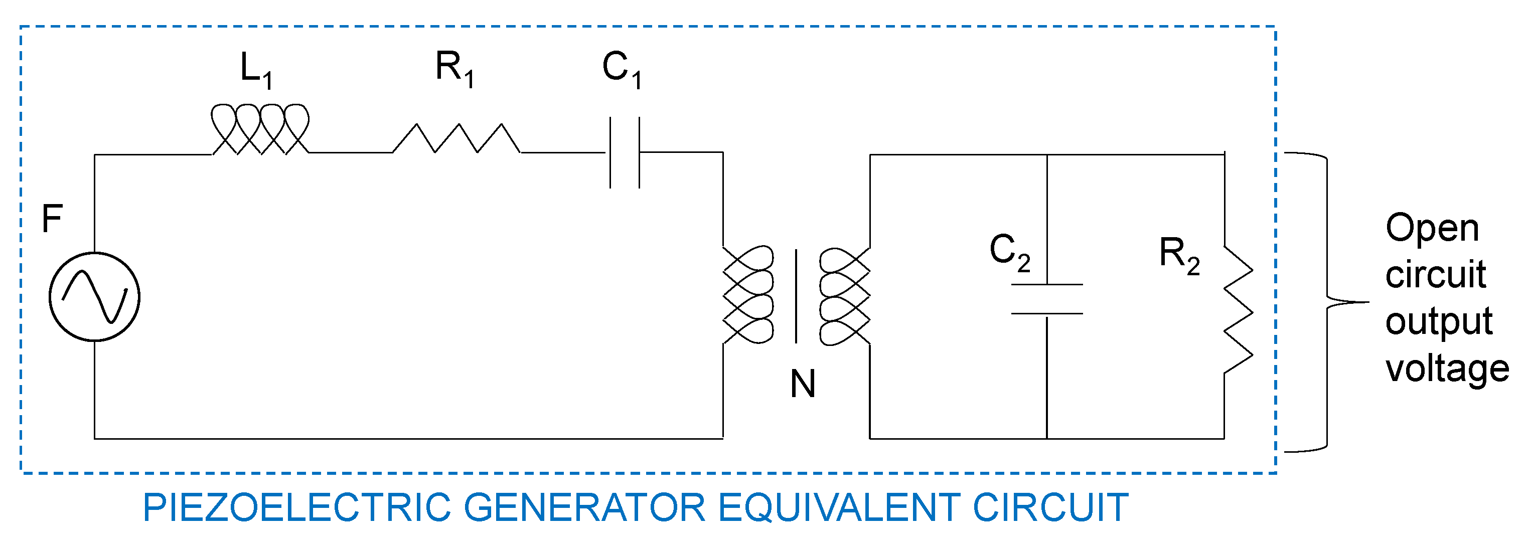
Figure 1 represents the piezoelectric generator equivalent circuit with all the electromechanical parameters used in the simulation process named. In this case, the first circuit mesh is related to the mechanical harvester parameters; specifically,
F refers to the applied mechanical excitation,
R1 refers to the damping coefficient defined as the relation between the force applied to a solid body and the speed it acquires as a consequence, and
C1 refers to the inverse of the stiffness (this means the relationship between the force applied to a solid body and the displacement that it causes as a consequence). On the other hand,
L1 refers to the inertia of the system. The hypothesis that relates the inertia of a solid body with inductance in the electrical model is a bit more complex than the previous two. As defined by [
27], this hypothesis is based firstly on the proportion between the electrical potential of a piezoelectric harvester and the applied force, and secondly on the capacity of the dipole charge generation as a consequence of the resulting speed of the harvester due to the vibration conditions. Finally, these two phenomena determine the amount of electrical current generated, as well as the inductance, in the electrical circuit.
The coefficient, N, is the piezoelectric charge constant, the nexus between the mechanical parameters represented by the first mesh and the electrical parameters represented by the second mesh. This coefficient is an inherent parameter of the material, which depends on the category of piezoelectric material used. On the other hand, it indicates the proportion of mechanical strain energy that will be transformed into electrical energy, and conversely, it can also indicate how much strain will be caused by the application of an electric field. In circuit analysis, this transformation ratio is not common. The relation that the transformer represents is defined by [
27] as the voltage in mesh 1 with the integral of the current in mesh 2.
Finally, C2 represents the electrical equivalent output capacitor, and R2 is related to the electrical equivalent output resistor.
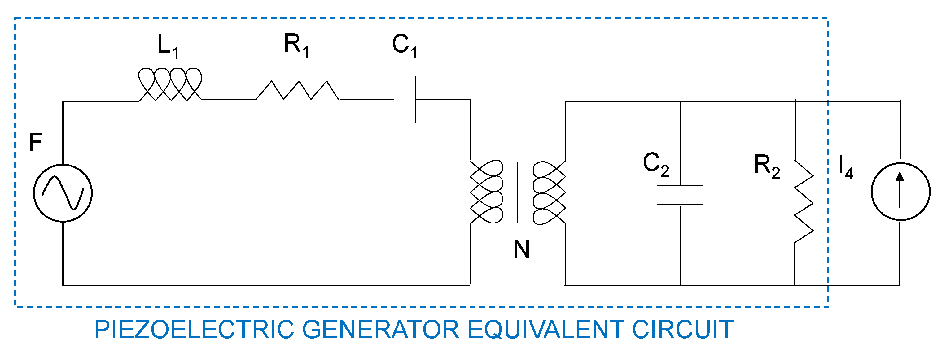
The analysis of the piezoelectric harvester behavior as an electrical power source with electromechanical parameter dependency has been performed with the help of some circuit systems situations. Firstly, the current source load situation is shown in
Figure 2; in this scenario, the harvester output voltage can be analyzed with the independence of the output current because it is determined by the load current source,
I4.
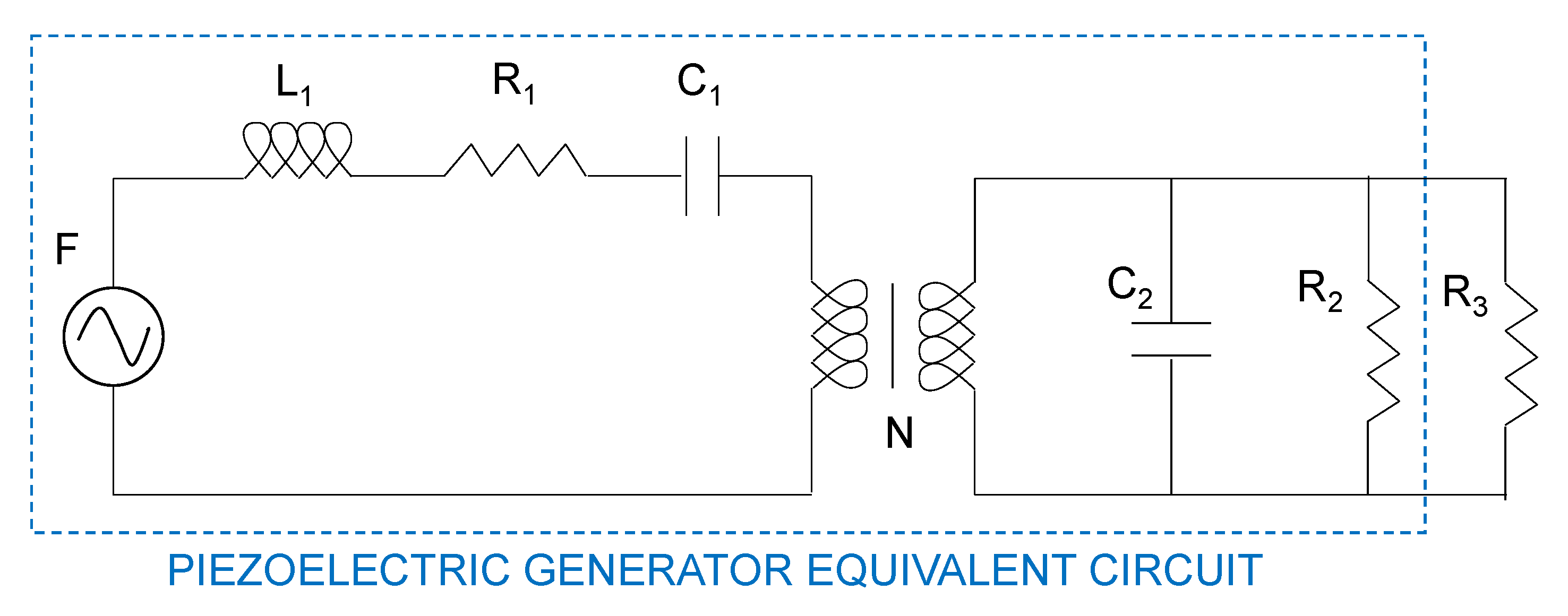
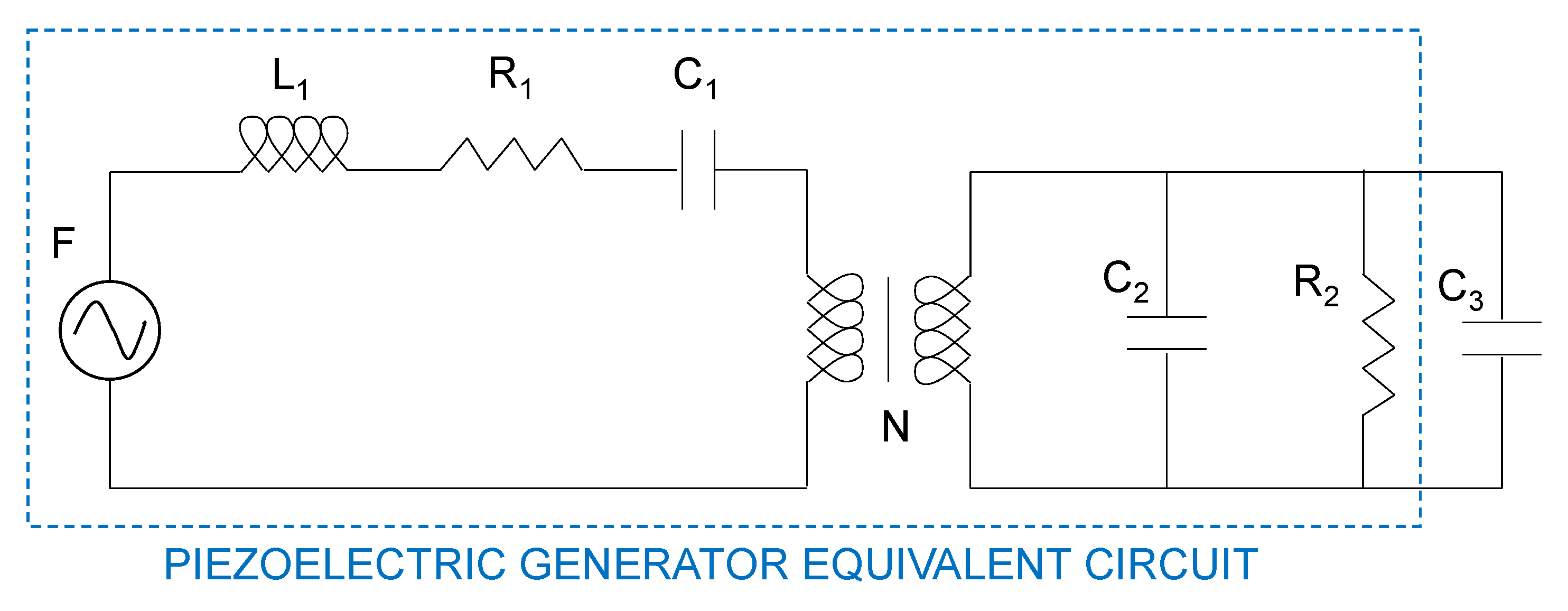
The next analysis steps are related to passive circuit loads, a resistive one (
Figure 3) and a capacitive one (
Figure 4). The objective of these system simulations is to evaluate the piezoelectric power source behavior with different nature loads. On the one hand, the output voltage has a dependence on the current demand, which can be simulated, and on the other hand, the system configuration allows making changes in the electromechanical parameters which moderate the piezoelectric harvester output. In this way, the simulation system design can involve different load scenarios, given information related to the variations suffered by the harvester output power as a consequence of piezoelectric material parameters and electric load changes.
In the next sections, the electric circuit systems presented are going to be mathematically modeled by the use of state-space equations in the Laplace transform domain. The simulations developed are evaluated with different piezoelectric charge constants, in order to determine the different behaviors associated with the piezoelectric coupling level. On the other hand, the piezoelectric mechanical parameters, stiffness, and damping are going to be analyzed in order to determine their influence on the piezoelectric power source output voltage. Finally, the influence of these mechanical parameters is evaluated related to the piezoelectric coupling level.
3. Results
All the electrical circuit systems described above for the representation of the piezoelectric harvester power supply, in different load configurations, have been simulated using the state-space equations in the Laplace transform domain. This technique is normally used in electrical circuit analysis because it is a powerful tool for circuit simulations, avoiding the use of differential equations. In this way, the implementation of the simulation diagram,
Figure 5, allows a precise simulation tool for the piezoelectric generator behavior.
However, all the electrical circuit systems described in
Section 2 must be analyzed and described by the state-space equations in order to configure the matrix system (A, B, C) used in the Laplace simulation process,
Figure 5. Firstly, circuit 1, represented in
Figure 1, is described. In this case, the first mesh electrical current is named
I1, and the electrical current that goes through
C2 is named
I2; secondly, the electrical current that goes through
R2 is named
I3; and finally,
V1 is the output voltage.
In circuit 2, represented in
Figure 2, the first mesh electrical current is named
I1, the electrical current that goes through
C2 is named
I2, the electrical current that goes through
R2 is named
I3, and finally,
V1 is the output voltage. In this circuit, a new current,
I4, appears, referring to the current source load.
In circuit 3, represented in
Figure 3, the first mesh electrical current is named
I1, the electrical current that goes through
C2 is named
I2, the electrical current that goes through
R2 is named
I3, the electrical current that goes through
R3 is named
I4, and finally,
V1 is the output voltage.
Finally, in circuit 4, represented in
Figure 4, the first mesh electrical current is named
I1, the electrical current that goes through
C2 is named
I2, the electrical current that goes through
R2 is named
I3, the electrical current that goes through
C3 is named
I4, and finally,
V1 is the output voltage.
4. Discussion
The results obtained through the simulations are going to be represented and analyzed, comparing the differences between low and high coupled systems. The output root mean squared (RMS) voltage in the open circuit scenario is obtained through variations in stiffness and damping. As has been previously defined by [
24], when the stiffness has a higher value, the relationship between displacement (
x) and force applied (
F) is higher too; this means that the same force applied produces a larger displacement, which is related to the harvester output voltage [
28]. On the other hand, when the damping is lower, the relationship between speed acquired (
v), and force applied, is higher; this means that the same force applied produces a larger speed, which is related to the harvester current [
28].
As expected, if
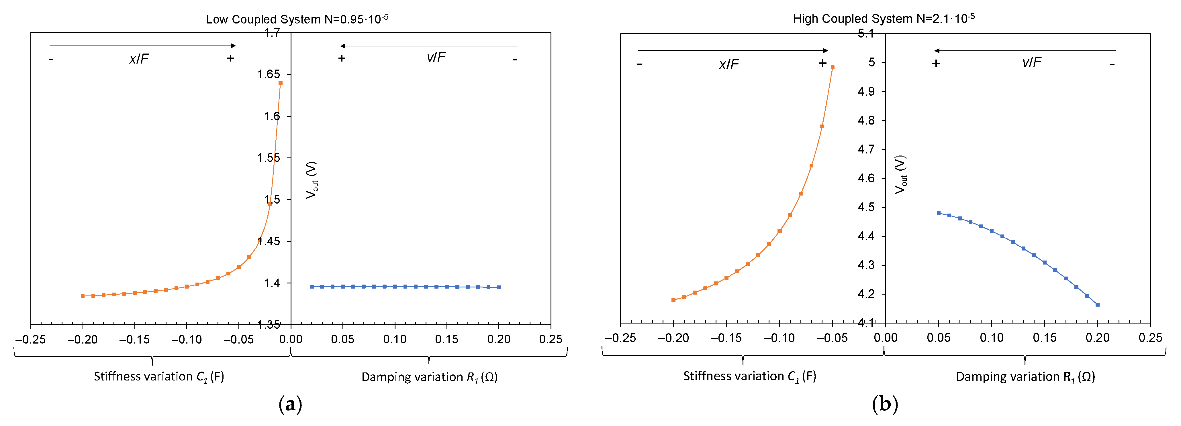
Figure 6a,b is compared, a higher voltage output is obtained for a higher coupled system. On the other hand, in
Figure 6a, it can be seen how, in spite of the fact that the stiffness variation produces a voltage increase, the damping variation does not produce any voltage change. The reason for that behavior is the relationship between speed and current; the damping variation produces an increase in the harvester output current, which does not have any impact on open circuit measurement. However, if the same coefficient variations are analyzed in a high coupled system (
Figure 6b), the result changes. In this case, the damping variation produces an output voltage variation, this means that in high coupled systems, the harvester voltage output is influenced by stiffness and damping variations, or, in other words, by displacement and speed variations. The difference between the tendency of the voltage increases with the analyzed coefficient variations is also noteworthy. The stiffness variation produces an exponential voltage increase; however, the damping variation produces a voltage increase, which tends to hold a constant value.
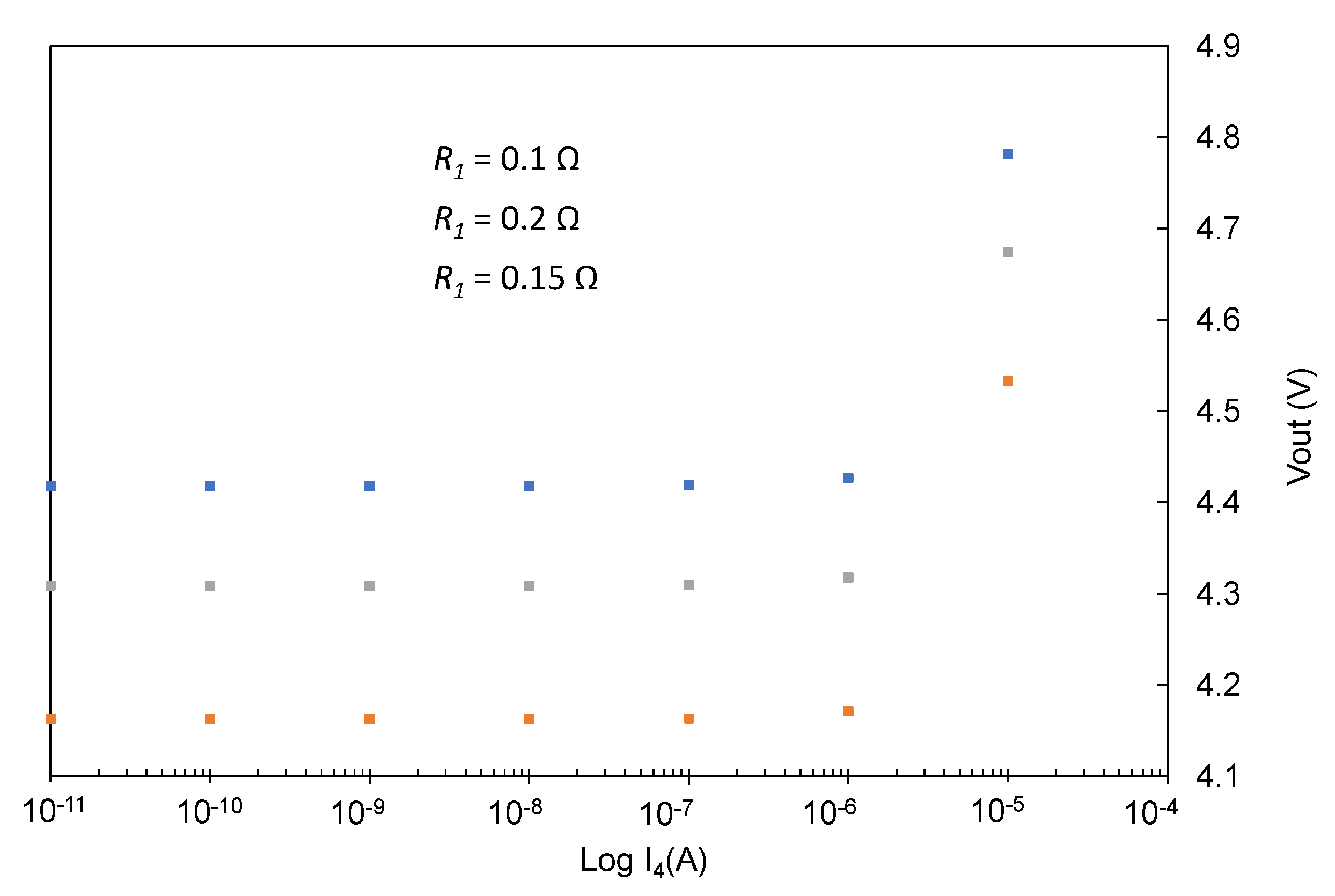
After the open circuit simulation results have been analyzed, new simulations have been performed in order to study the voltage variations produced by damping coefficient changes in high coupled systems. For that reason, the next figure corresponds to the output voltage measured in a current source load situation (
Figure 2).
Firstly, the results obtained in
Figure 7 show an increase in the output voltage measured with a decrease in the damping, as could be seen in the open circuit voltage simulation too (
Figure 6). On the other hand, when the current source value,
I4, decreases, the output harvester voltage also decreases as expected, but for certain
I4 current values, the voltage maintains a fixed value only dependent on the damping coefficient. These fixed values are the same output voltages obtained in
Figure 6b. After analyzing these results, a conclusion can be extracted; in high coupled systems, an output minimum voltage value is obtained that is not dependent on the output current but delimited by the relationship between the force applied to the harvester and the speed acquired by the harvester.
The next results analyzed are the simulations corresponding to resistive and capacitive loads in a high coupled system (
Figure 3 and
Figure 4) in order to visualize the variations obtained in the output voltage and transmitted power for different loads. In
Figure 8, the output voltage results for different resistance load situations are represented, applying a stiffness variation (a) and applying a damping variation (b), evaluated for the same load resistances,
R3.
The results obtained for the stiffness variations show an exponential increase in the output voltage when the stiffness increases, as could be previously seen in
Figure 5. The voltage also increases with a higher resistance load value; this behavior is a consequence of the relationship between voltage, current, and resistance because, for the same available current and fixed piezoelectric parameters, a higher resistance produces an increase in the output voltage. On the other hand, the results obtained in the output voltage for damping variations are more difficult to understand. As can be seen in
Figure 8b, there is a maximum value of voltage that the three resistive loads could reach, and every one of them receives that value for different damping values. This behavior can be explained through the maximum power that the harvester is able to transmit. The electrical power available is the product of the current and the voltage, but these two parameters are also fixed by the load resistance. As previously mentioned, the damping factor is closely related to the current generated by a piezoelectric harvester; when the damping is reduced, the current is increased, so the voltage is also increased for a constant resistance value; however, when the voltage reaches a maximum value corresponding to the maximum electrical power available, if the current continues increasing, the voltage needs to decrease to maintain a constant power product.
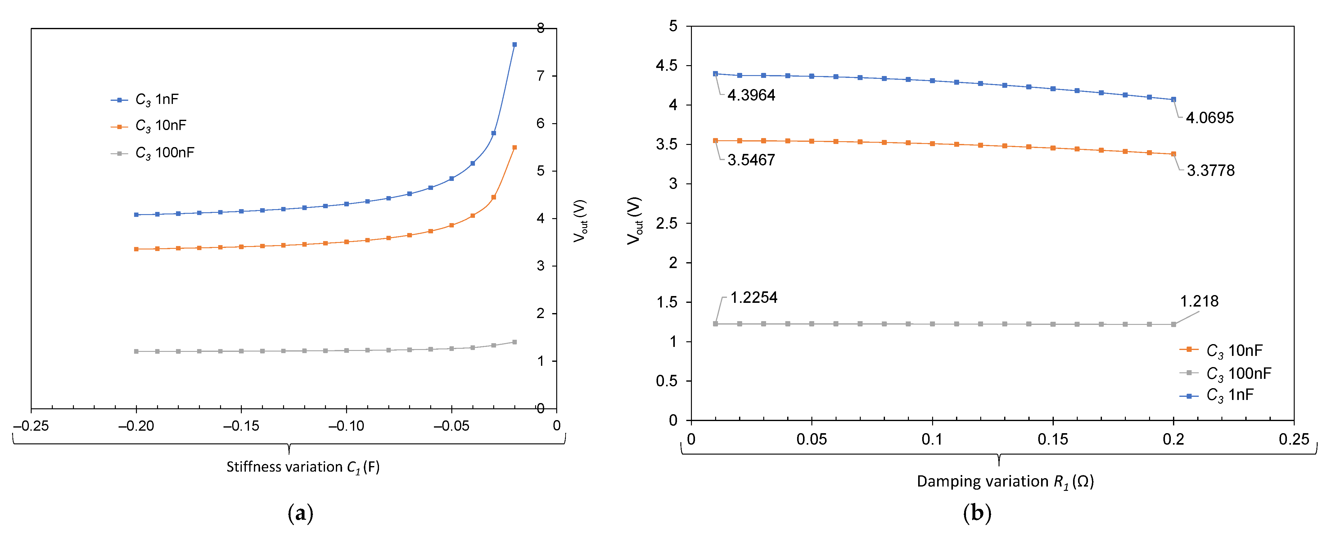
Finally, the results obtained for the capacitor load situation,
Figure 9, are analyzed. In
Figure 9a, the output voltage obtained presents an exponential variation with the stiffness, this behavior is amplified with a smaller capacitor due to the relationship between voltage, current, and capacitive loads. On the other hand, the damping variations also produce a change in voltage, albeit less significant. In this case, the voltage is also higher with a lower capacitor due to a lower current necessity for completing the charge and reaching a voltage output.
