Article

Trajectory Recovery Based on Interval Forward–Backward Propagation Algorithm Fusing Multi-Source Information

1
School of Internet of Things Engineering, Jiangnan University, Wuxi 214122, China
2
Affiliated Wuxi Mental Health Center of Jiangnan University, Wuxi Central Rehabilitation Hospital, Wuxi 214151, China
3
Department of Electronic Engineering, Kwangwoon University, Seoul 139-701, Korea
4
School of Information Science and Engineering, Linyi University, Linyi 276012, China
*
Author to whom correspondence should be addressed.
Electronics 2022, 11(21), 3634; https://doi.org/10.3390/electronics11213634
Submission received: 2 September 2022 / Revised: 26 September 2022 / Accepted: 5 October 2022 / Published: 7 November 2022

Abstract

:
In the tracking scheme in which global navigation satellite system (GNSS) measurement is temporally lost or the sampling frequency is insufficient, dead reckoning based on the inertial measurement unit (IMU) and other location-related information can be fused as a supplement for real-time trajectory recovery. The tracking scheme based on interval analysis outputs interval results containing the ground truth, which gives it the advantage of convenience in multi-source information fusion. In this paper, a trajectory-recovery algorithm based on interval analysis is proposed, which can conveniently fuse GNSS measurement, IMU data, and map constraints and then output an interval result containing the actual trajectory. In essence, the location-related information such as satellite measurement, inertial data, and map constraints is collected by practical experiments and then converted into interval form. Thereby, the interval-overlapping calculation is performed through forward and backward propagation to accomplish the trajectory recovery. The practical experimental results show that the trajectory recovery accuracy based on the proposed algorithm performs better than the traditional Kalman filter algorithm, and the estimated interval results deterministically contain the actual trajectory. More importantly, the proposed interval algorithm is approved to be convenient to fuse additional location-related information.

1. Introduction

With the development of positioning and navigation technology, the global navigation satellite system (GNSS) module is widely used in various smart devices, such as mobile phones, autonomous vehicles, etc. The generated position and trajectory data can be used to ensure the safety of users and provide them with more location-based services (LBSs), such as vehicle navigation [1], and driving behavior analysis [2], etc. However, the effectiveness of these services relies on the sampling rate of trajectory data, and the trajectory with low sampling rate will lose the key information of moving targets and increase the uncertainty between sampling points. In addition, the high uncertainty between the continuous sampling points of the trajectory will also seriously affect the relevant research on the trajectory, including trajectory clustering analysis [3], trajectory indexing [4], and trajectory classification [5]. Therefore, it is necessary to develop a high-quality trajectory-recovery algorithm based on the original low-sampling GNSS data.
To obtain high sampling rate trajectory data, many efforts have been made in the literature. However, there are two problems to be solved with current existing research schemes. First, many methods are based on numerical algorithms, including the dead reckoning (DR) algorithm [6,7] and the Kalman filter algorithm [8,9], etc. However, they lack consideration of error, or cannot solve the error accumulation, and the final estimated result is far from the actual value. Secondly, many studies cannot provide a framework to integrate the map information and points of interest available in the road network [9,10,11] in a convenient manner.
The main contributions of this paper can be summarized as follows. By investigating the above state-of-the-art trajectory recovery schemes, this paper proposes an interval forward–backward propagation algorithm (FBP), which can integrate the measurement data of multiple sources for target tracking, such as the inertial navigation data, the GNSS data, and the map constraint information. The novelty of our proposed trajectory-recovery scheme lies in two main contributions.
  • The first contribution is to propose a new, reliable framework with which to fuse various positioning location-related information more conveniently. Because the data of inertial navigation information, GNSS information, and map constraint information contain uncertainty, an information fusion method by intersection operation proposed in this paper is suitable for the fusion of multi-source information;
  • The second contribution is that a novel algorithm proposed in this paper can ensure that the actual trajectory of the target is included in the trajectory interval result calculated by the proposed algorithm.
The remainder of this paper is organized as follows. Section 2 describes the work related to trajectory recovery. Section 3 briefly introduces the proposed system model proposed in this paper. Section 4 shows the experiment and some simulation results. Section 5 analyzes and summarizes the effect of this algorithm.

2. Related Works

In this section, we review the existing research work on trajectory recovery, including trajectory recovery works based on interval analysis [12,13,14,15,16,17], and other studies which fail to consider map information integration [18,19,20,21,22].
In recent years, there have been many outstanding research programs in the field of location tracking and trajectory recovery. For example, Wang et al. proposed a deep hybrid trajectory recovery model based on the current popular artificial intelligence method in [9], aiming to achieve intelligent trajectory recovery. However, the application of depth learning is still inadequate for some nonlinear trajectory recovery scenes. Therefore, based on the good performance of interval analysis in the field of mechanical control research [12], many researchers expect interval analysis to have good performance in track recovery and accurate positioning because interval analysis can eliminate the uncertainty in data acquisition and plays an important role in nonlinear state estimation. As expected by scholars, the interval analysis method significantly improves the accuracy of vehicle location and trajectory recovery. Soares et al. proposed a target tracking method based on interval analysis [13], in which the error of the vehicle location error obtained was smaller than that of the particle filter. However, the experimental result of Soares et al. shows that the interval results are messy, which will increase the error of local positioning points. Traditionally, the vehicle is usually modeled as a grid, and the trajectory of the vehicle is modeled as a line. This usually leads to great uncertainty between the estimated trajectory and the actual trajectory. Therefore, Xu et al. modeled the automated guided vehicle (AGV) as an interval and estimated its trajectory interval [14]. The problem of the large deviation between the estimated trajectory and the actual trajectory is solved by this method. However, the author limited the value of the AGV yaw angle in the experiment, so the method may not be available in the actual situation. In [15], Hamed et al. used high confidence intervals to estimate the trajectory and altitude of the aircraft, and the result shows that the estimated trajectory area is still growing. In addition to the messy interval and the large area of the interval, researchers rarely pay attention to the correction of GNSS for track recovery. Therefore, Wang et al. proposed the method of interval analysis and GNSS integration to estimate the vehicle trajectory in [16]. Then, the estimated trajectory is compared with the trajectory of the DR algorithm, the results of which show that the trajectory obtained by interval and GNSS fusion is closer to the reference path. However, the trajectory interval obtained by Wang et al. was obtained through experiments on uncovered roads, and they did not verify whether their method was suitable for GNSS interference. In [17], Ghalia et al. proposed the use of bounds-error estimation (BEE) and belief-state estimation (BSE) to get the trajectory of the vehicle in the nonlinear state and compared it with the trajectory obtained by the particle filter. The results show that the accuracy of BSE is higher. The method of Ghalia et al. has been optimized in the research field of trajectory estimation. However, the trajectory obtained by their method still has the problems of large intervals area and messy intervals. These problems will cause the estimated vehicle trajectory to deviate from the actual road.
Positioning based on the map information measured can improve the positioning accuracy and improve the robustness of positioning algorithms, such as radar data and road scene images [18], road visual features collected by using road scene fingerprints, or 3D features [20]. However, they pay little attention to the map information in actual situations, so they lose the information to improve positioning accuracy. In this case, Wang et al. proposed to use the node information of streets and buildings (OpenStreetMap) for precise positioning in [19]. This positioning method improves the location accuracy of urban scenes. However, due to the lack of improvement in the accuracy of suburban location, Wang et al.’s precise location method lacks universality. In order to find the map information that can be used for general positioning, lm et al. proposed to use the vertical angle characteristics of buildings and ground as the map information for precise positioning in [21]. Experiments show that this method can improve positioning accuracy compared with other methods. However, the measurement of the map information requires the use of the 2D radar, which is not applicable to general real-time positioning scenarios. Oh et al. used lidar and stereo vision sensors to measure obstacles in the course of vehicle movement as map information [22], and then proposed an occupation grid filter to fuse the map information. This method of merging map information and sensor information can obviously improve the positioning accuracy of vehicles. The experiment shows that the location error distance is in a stable range. Therefore, the map information can really help improve positioning accuracy. However, when the map information is difficult to measure [18,20], or the map information lacks universality [21], or the survey map information cannot be easily and quickly integrated with the proposed method [22], the applicability and efficiency of the positioning system will be reduced.
The above trajectory-optimization algorithms are suitable for the research of trajectory recovery. However, many kinds of map information in the road network have not been integrated and analyzed. To the best of our knowledge, a significant point of our work is that map constraint information is added and integrated with inertial sensor information and GNSS information to perform the trajectory recovery research. The actual experiment also proves that the trajectory calculated by our proposed method is more effective.

3. Trajectory Recovery Frameworks

Before describing our proposed FBP algorithm, we shall first introduce the existing GNSS/IMU based trajectory recovery framework for comparison. Table 1 lists the notations in this paper.

3.1. Kalman Filter Based Trajectory Recovery Framework

First, we introduce the traditional Kalman filter algorithm into the considered trajectory recovery scenario for comparison. When the positioning environment is limited or the positioning sampling is insufficient, the research methods of accurate positioning and trajectory recovery mainly combine GNSS and inertial navigation units based on the Kalman filter algorithm.
The most common GNSS/IMU positioning is multi-source fusion technology. First, the DR algorithm is used to calculate the position of moving targets, and then the GNSS coordinate points are used to correct the calculated position data. According to the dead reckoning algorithm [23], the formula is as follows:
{ S x ( t ) = v ( t ) τ cos θ ( t ) + 1 2 a x ( t ) τ 2 S y ( t ) = v ( t ) τ sin θ ( t ) + 1 2 a y ( t ) τ 2 .
After data fusion using the DR algorithm, the coordinate points converted by GNSS are used to correct the large deviation displacement coordinates obtained by the DR algorithm. Due to the error accumulation of the IMU sensor, the error between the moving target trajectory and the actual trajectory corrected by GNSS in the DR algorithm will be large. Now we introduce the Kalman filter algorithm to correct the integration result of the DR algorithm [24].
We establish the following Kalman filter model:
{ x ( k ) = A x ( k 1 ) + B u ( k ) + w ( k ) z ( k ) = H x ( k ) + y ( k ) .
It can be seen from the above formula that the Kalman filter algorithm can reduce the position drift caused by the heading error and fault zero velocity measurement.

3.2. Interval Forward and Backward Propagation Trajectory Recovery Framework

Inertial navigation-integrated positioning will generate error accumulation, and the Kalman filter can be used to mitigate the error accumulation. However, the results of the Kalman filter framework may also generate errors due to the nonlinear motion model. In addition, the traditional numerical operation cannot guarantee that the actual trajectory of the vehicle exists in the calculation result, compared with the interval operation. Thus, the first goal of the proposed FBP method is to ensure that the actual trajectory of the vehicle exists in the calculated trajectory interval. In other word, our proposed FBP algorithm will provide a deterministic result containing the ground truth.
The proposed algorithm is explained as follows. We need to briefly introduce the process of interval analysis [25]. Interval analysis can be defined as the extension of classical real arithmetic operators to set theory. The intervals are defined by a lower and an upper bound, which are x inf and x sup respectively. Therefore, an interval [ x ] = [ x inf , x sup ] is defined as the set of all real numbers between those bounds [26,27]. The implicit meaning is that we only know the true value x * is guaranteed to be in the interval [ x ] , i.e., x * [ x ] . For example, the detection error of GNSS equipment can generally be accurate to ± 5 meter, so its real error exists in the interval [ 5 , 5 ] meter.
Step 1. In this paper, we transform the collected data into interval data, such as acceleration, yaw angle, velocity, and the GNSS coordinates. The upper and lower limits of these data are defined by their normal distribution [26]. Then, we fused the segmented data to obtain the displacement interval of each time slot,
[ S ] ( t ) = [ v ] ( t ) f ( [ [ θ ] ( t ) ] ) + 1 2 [ a ] ( t ) τ 2
f ( [ [ θ ] ( t ) ] ) = { cos [ [ θ ] ( t ) ] , X   direction sin [ [ θ ] ( t ) ] , Y   direction .
It should be noted in Equations (3) and (4) that because the sampling time interval is fixed, we think that the interval τ is a real constant.
Step 2. When we solve kinematic problems, we often encounter the following equation:
[ x ] ( t + τ ) = [ x ] ( t ) + [ S ] ( t ) .
In practice, the initial GNSS point and the end GNSS point are available. After obtaining the displacement interval [ S ] ( t ) at each sensor sampling time through Equation (3), we can obtain the trajectory interval at any sensor sampling time between two GNSS points through Equation (5). The trajectory coordinates of the two GNSS points have been determined. Therefore, we can use the method of interval intersection to reduce the trajectory area. In addition, the intersection of the end GNSS coordinate interval and the forward trajectory interval can constrain the area of the trajectory interval because the end GNSS coordinate is available. We can get the trajectory interval of the backward propagation as shown in Equation (6):
[ x ] ( t τ ) = [ x ] ( t τ ) ( [ x ] ( t ) + [ S ] ( t τ ) ) .
Equation (6) is the calculation process of vehicle’s trajectory from the end GNSS point to the initial GNSS point. The trajectory interval at each sampling time needs to intersect with the track interval estimated by the forward propagation in this way. Through Equation (6), the backward propagation interval can be constrained to estimate a definite interval. In particular, the reason why the displacement interval of the previous time slot is used here is that we calculate from the later time to the previous time. In practice, the initial trajectory coordinates and destination trajectory coordinates of the vehicle are known.
Step 3. A new optimized trajectory point is obtained by intersecting the end GNSS coordinate interval with the estimated trajectory interval in step 2. In fact, we also obtain a new optimized trajectory at the initial point or a sensor sampling point. At this time, we need to constrain the area of the entire trajectory interval through new forward propagation:
[ x ] ( t + τ ) = [ x ] ( t + τ ) ( [ x ] ( t ) + [ S ] ( t ) ) .
It should be noted that [ x ] ( t ) is the constrained trajectory interval, and [ x ] ( t ) is the trajectory interval estimated by the initial forward propagation (or forward and backward propagation, as shown in Algorithm 2). Because “interval forward and backward propagation” calculates the trajectory between two GNSS points, we know the trajectory coordinates of vehicle at the two GNSS points. Here, we define them as the initial GNSS interval [ x ] ( 0 ) and the end GNSS interval [ x ] ( k ¯ ) . The introduction of the FBP algorithm is as follows.
In Algorithm 1, we use three functions to calculate the illustrative indicators in this paper. Next, we will explain the definitions of these three functions. Before introducing the three formulas, we first need to know that [ x ] ( t ) includes the trajectory interval of the vehicle along the X direction and the Y direction (the X direction is the orientation of the vehicle at the initial time, and the Y direction is a direction perpendicular to the orientation of the vehicle at the initial time). Therefore, [ x ] ( t ) can be formulated as:
[ x ] ( t ) = [ [ x X ] ( t ) [ x Y ] ( t ) ] .
Hence, the three functions in Algorithm 1 can be formulated as:
f m i d ( [ x ] ( t ) ) = ( x X sup + x X inf 2 , x Y sup + x Y inf 2 )
f l e n t h ( [ x ] ( t ) ) = x X sup x X inf
f w i d t h ( [ x ] ( t ) ) = x Y sup x Y inf .
Algorithm 1 FBP (Interval based forward backward propagation)
    Input: [ x ] ( 0 ) , [ x ] [ k ¯ ] , [ S ] ( t ) , k ¯
    Output: [ x ] ( t ) , [ x ] ( t ) , x t r ( t ) , a r e a ( t )
1
  Initialize: [ x ] ( t ) =   [ x ] ( t ) =
2
   x t r ( t ) 0 ;
3
   a r e a ( t ) 0 ;
4
    for   t = 0   to   k ¯  do
5
         if   t + τ = k ¯  then
6
                  [ x ] ( t ) = [ x ] ( t ) [ x ] ( k ¯ )
7
         else if  t + τ k ¯  then
8
                     [ x ] ( t + τ ) = [ S ] ( t ) + [ x ] ( t )
9
         end if
10
  end for
11
   for   t = k ¯   to   d t  do
12
            [ x ] ( t τ ) = ( [ x ] ( t ) [ S ] ( t τ ) ) [ x ] ( t τ )
13
  end for                                    //interval-based backward propagation step
14
  for  t = 0 to k ¯  do
15
           x t r ( t ) = f m i d ( [ x ] ( t ) )
16
           a r e a ( t ) = f l e n t h ( [ x ] ( t ) ) · f w i d t h ( [ x ] ( t ) )
17
  end for
In Algorithm 1, we transformed the date of various sensors and GNSS coordinates into interval data, and obtained the vehicle’s trajectory interval [ x ] ( t ) through the forward propagation. It is shown as a box for a sampling point of the trajectory. By intersecting the calculated trajectory interval with the end GNSS point, we estimate the optimized trajectory interval [ x ] ( k ¯ ) , and then the trajectory interval [ x ] ( t ) of the FBP will be estimated.
From the introduction in Section 1 and Section 2, we know that our work not only proposes a FBP algorithm to calculate the vehicle’s trajectory but also proposes to fuse the map constraint information in the road network, which will make the interval result more accurate. In addition, our proposed algorithm is more effective for the fusion of multiple incompatible map information. Next, we will introduce the process of the FBP algorithm to fuse map constraint information. Let’s see why our method is effective for the integration of multiple incompatible information.
It can be seen from Algorithm 2 that the map information can be converted into interval data [ M a p c ] and used as the input of the backward propagation algorithm. The optimized trajectory interval under map constraint information is obtained by intersecting the map constraint interval data with the trajectory interval obtained from Algorithm 1. Then, the trajectory interval of the FBP algorithm integrating map constraint information [ x m ] ( t ) is obtained through the forward propagation and backward propagation, respectively.
Algorithm 2 FBP algorithm with map constraint information
      Input: [ x ] ( t ) , [ S ] ( t ) , [ M a p c ] ,  k ¯ , t m
     Output: [ x m ] ( t ) , x t r ( t ) , a r e a ( t )
1
   Initialize: [ x m ] ( t ) =
2
    x t r ( t ) 0 ;
3
    a r e a ( t ) 0 ;
4
   [ x m ] ( t m ) = [ x ] ( t m ) [ M a p c ] //Integrated map constraint information
5
  for  t = t m to τ  do//Interval backward propagation algorithm
6
           [ x m ] ( t τ ) = [ x ] ( t τ ) ( [ x m ] ( t ) [ S ] ( t τ ) )
7
end for
8
for t = t m to k ¯ τ  do //Interval forward propagation algorithm
9
          [ x m ] ( t + τ ) = [ x ] ( t + τ ) ( [ x m ] ( t ) + [ S ] ( t ) )
10
end for
11
for t = 0 to k ¯ do
12
          x t r ( t ) = f m i d ( [ x m ] ( t ) )
13
          a r e a ( t ) = f l e n t h ( [ x m ] ( t ) ) · f w i d t h ( [ x m ] ( t ) )
14
  end for

4. Experiment Data and Analysis

4.1. Experimental Environment

In this experiment, a hardware platform was built, and a moving vehicle equipped with multi-sensors and a positioning system was made for data acquisition and storage. The hardware platform is shown in Figure 1c. The motion attitude parameters are collected in real time by inertial sensors with a sampling interval of 1 s. These attitude parameters include acceleration, motion yaw angle, and velocity. Then, the positioning system is fitted to the moving target to obtain the longitude coordinate and latitude coordinate of the vehicle. The sampling time interval is 5 s to simulate the low sampling rate of GNSS information. Figure 1a shows the actual trajectory and the trajectory performed from GNSS data convert to the collected longitude and latitude coordinates by inverse cylindrical projection [28]. Figure 1b shows the actual experimental scene in Figure 1a. Because our research scenario is the movement of a vehicle on wheels, if the sampling rate is high enough, we believe that the trajectory of the target is smooth in each GNSS and IMU sampling period. It should be emphasized that the above coordinate system gathered by inverse cylindrical projection is rectangular coordinates and measured in meters. We found that the vehicle’s trajectory estimation results can be completely presented in this coordinate system.
In the above figure, the red curve represents the curve of the plane coordinates obtained by the collected GNSS coordinates through Gaussian orthographic projection [28]. The blue curve represents the actual motion trajectory of the vehicle, and the black coordinate point is GNSS coordinate point. Due to the limitation of the actual experiment, we only marked and recorded the route of the vehicle and obtained the above blue curve. From the above figure, we can see that the actual trajectory curve is an irregular prototype, and the curve generated by GNSS point simulation is also close to this shape. It can be seen that the error between the curve generated by GNSS points and the actual trajectory of the vehicle is large. Therefore, it is ineffective to use only GNSS points with a low sampling rate for trajectory recovery.
As for the simulation environment, we used MATLAB and Python for joint debugging. We preprocessed the original data in MATLAB, and the trajectory data for comparison by GNSS/IMU integrated navigation and Kalman are calculated, the trajectory interval is calculated in Python by the proposed method. To show the computational cost of the proposed FBP algorithm, we also evaluate the elapsed time of different algorithms. The trajectory recovery data is fused on a personal computer carrying an Intel i7 processor with a main frequency of 2.60 GHz.

4.2. Map Constraint

As we reviewed in Section 1 and Section 2, in most of the localization tracking and trajectory recovery articles, the authors did not consider the integration of map constraint information in the road network in the algorithm. As we emphasized, in our work, we emphasized the integration of map constraint information. More importantly, the FBP algorithm we proposed can efficiently fuse map constraint information. Map constraint information refers to the available map information in the road network, such as bridges, crossroads, and other traffic locations. The GNSS coordinates of these locations are constrained [29,30,31,32], so map information can be used for the research of trajectory recovery. We get [ M a p c ] in Algorithm 2 by adding interval boundary to map constraint information. In addition, the motion record of the vehicle in the actual experiment is shown in Figure 1b. Map constraint information is shown in the following figure.
It can be seen from Figure 1b that our experiment is used to estimate the trajectory of the unknown area between the GNSS points. The actual trajectory points of the vehicle are manually marked. When the buzzer on the vehicle rings, it indicates that the sensor data is being uploaded to the cloud platform, and manual marking is also required at this time. In the actual road network, vehicles may run in load of the coordinates determined, such as bridges and crossroads (as shown in Figure 2), which can be considered as box-shaped areas. And the location information of these special places can be inquired and obtained from the traffic website. Therefore, the length and width of the box can be converted into an initial map information interval. The interval of the map constraint is shown in the orange area above.
In normal circumstances, the initial map information interval is inclined in the coordinate system we established (as shown in Figure 1a). Therefore, the initial map information interval needs to be mathematically modeled into components that can be fused by our algorithm. Here we take the outer minimum rectangle of the initial map information interval as our map constraint interval, and this map constraint interval will be paralleled to our coordinate system. In addition, the map constraint information we measured is located at the place of ninth sensor sampling time. The box interval of the map constraint [ M a p c ] is measured as [(11, 13), (−10.5, −8.5)].

4.3. Performance Metrics

We shall evaluate our proposed FBP algorithm in terms of the determinacy, accuracy, and computational cost, among which the determinacy implies whether the estimated interval result contains the ground truth.

4.3.1. Determinacy

As we want to express, the first role of our work is to guarantee the actual trajectory of the vehicle exists in the interval result calculated. Then, we will show the trajectory effect obtained by using the FBP algorithm.
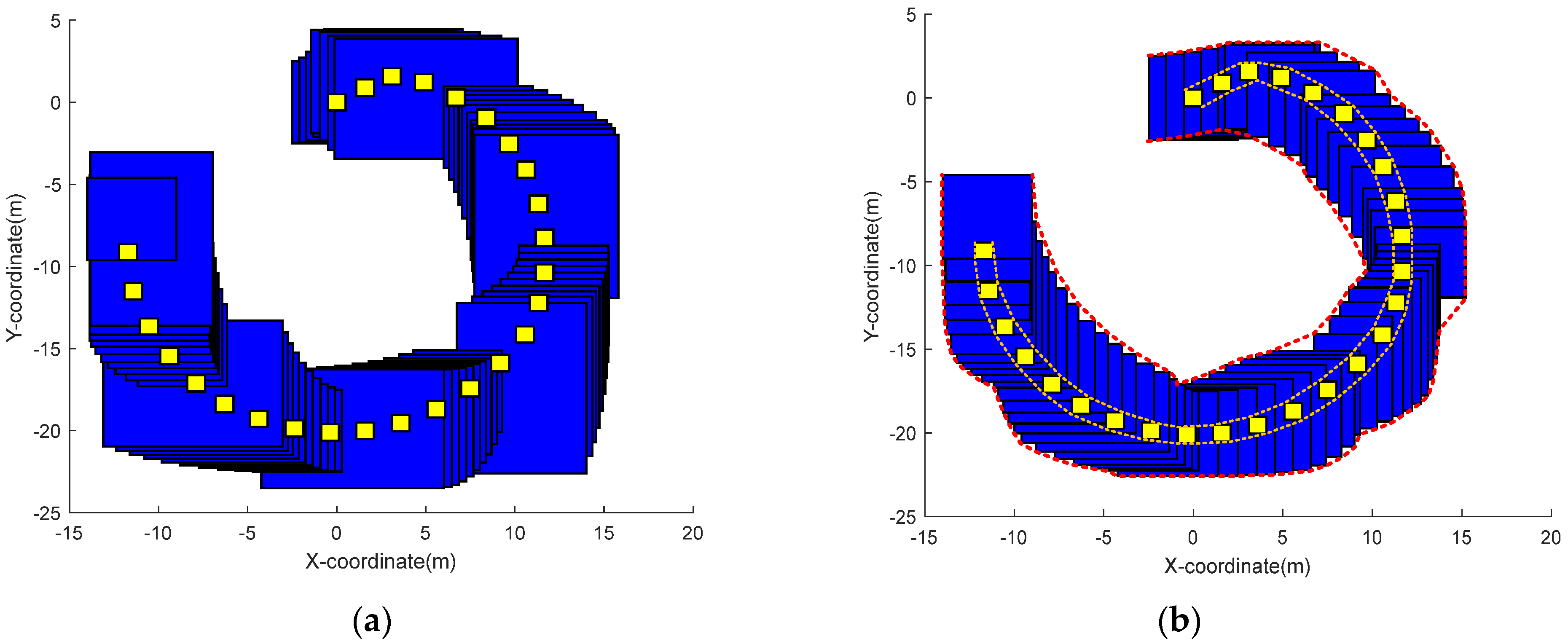
To illustrate the effectiveness of our method, first we get Figure 3a through the interval forward propagation algorithm, then we get Figure 3b through the FBP algorithm, and then the effect of adding map constraint information is shown in Figure 4.
In the above figure, the blue square represents the calculated track section of the vehicle, and the yellow square represents the actual track section of the vehicle. Among them, the actual trajectory interval of the vehicle is relatively small, because we can determine the actual position of the car through marking and measurement. After that, we set the manual measurement error to 0.25 m [33]. From the above figure, we can see that the blue square also presents a semicircular shape and completely contains the actual track section of the vehicle. For this reason, our method is effective.

4.3.2. Accuracy

In this section, we mainly implement Algorithm 2. To highlight the efficiency of our method, we use the DR algorithm and Kalman filter algorithm as a comparison. The DR algorithm and Kalman filter algorithm are currently considered to have a good trajectory recovery effect.
To the best of our knowledge, this paper is the first work that combines map constraint information with trajectory recovery. We introduce the experimental design in Section 4.3 as follows:
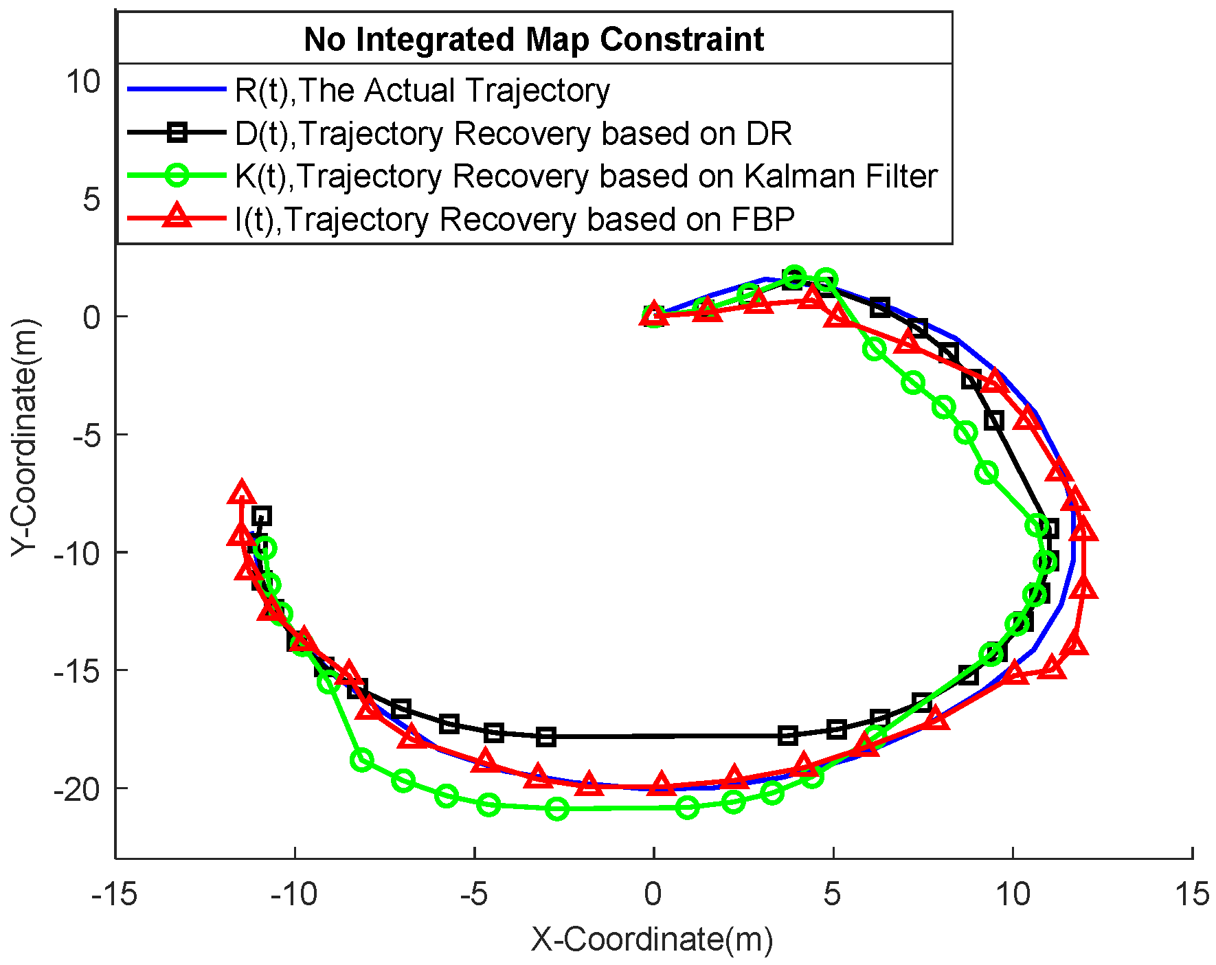
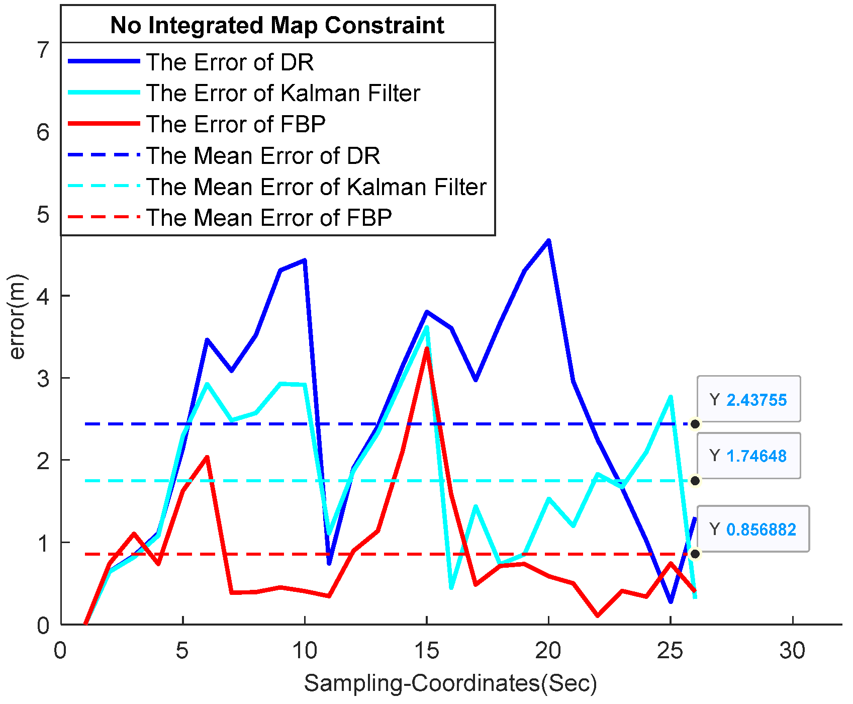
  • First, we performed the vehicle’s trajectory recovery based on the DR algorithm and Kalman filter algorithm by integrating the GNSS information, which is also the method adopted by most of the current work. However, the above experiment did not include map restriction information. As a comparison, we get the vehicle’s trajectory interval based on Algorithm 1. The result comparison is shown in Figure 5, and the error analysis result is shown in Figure 6;
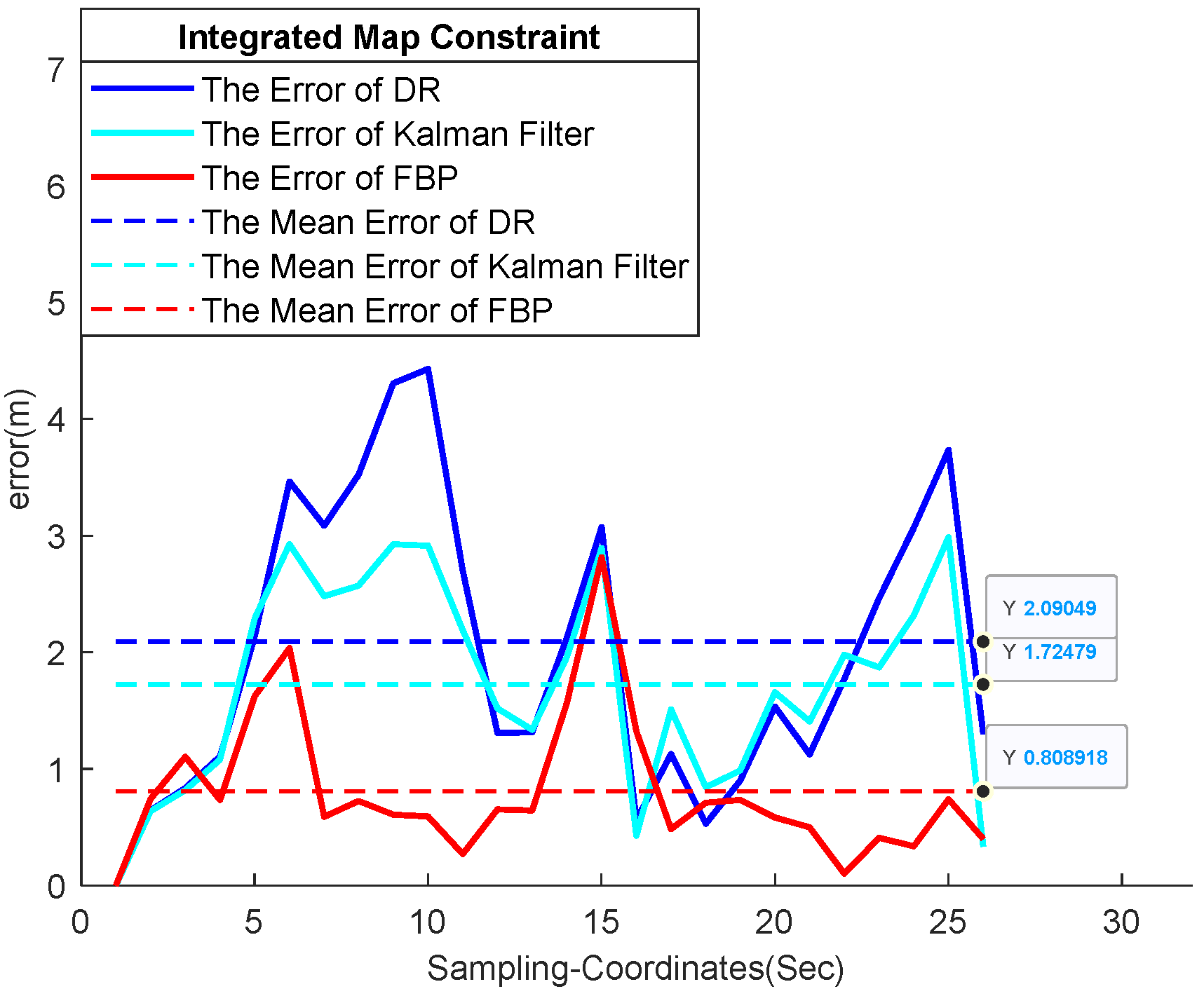
  • Secondly, to show that our algorithm has good compatibility with map information, we also integrated map constraint information into the DR algorithm and Kalman filter algorithm. Finally, the interval results of Algorithm 2 are used for comparison. The comparison considering the map constraint is shown in Figure 7, and the error analysis results are shown in Figure 8;
Next, we will analyze and introduce Figure 5, Figure 6, Figure 7 and Figure 8. First, we will introduce the curve definitions in Figure 5 and Figure 7. The black curve D ( t ) of the marked square is the trajectory curve based on the DR algorithm, the green curve K ( t ) of the marked hollow circle is the trajectory curve based on the Kalman filter algorithm, and the red curve I ( t ) of the marked triangle is the trajectory curve based on the FBP algorithm. It should be noted that the value I ( t ) is the same as x t r ( t ) described in Algorithm 1. For clarity, we define the trajectory of the FBP algorithm as I ( t ) . In Figure 6 and Figure 8, the blue curve is the error curve between the DR algorithm and the actual vehicle’s trajectory, the cyan curve is the error curve between the Kalman filter algorithm and the actual vehicle’s trajectory, and the red curve is the error curve between the FBP algorithm and the actual vehicle’s trajectory. More importantly, we calculated the mean square error value of the above errors and marked them as blue, cyan, and red dashed lines on the figure.
We can find that the curve I ( t ) based on the FBP algorithm is close to the actual trajectory curve R ( t ) of the vehicle, but the curve D ( t ) and curve K ( t ) are significantly away from the trajectory curve R ( t ) . This phenomenon can be seen in Figure 5 and Figure 7. In particular, we can find that in Figure 6 and Figure 8, the mean error of the FBP algorithm is much smaller than that of the DR algorithm and Kalman filter algorithm. This shows the effectiveness of our proposed algorithm.
In Figure 5, the vehicle runs from the coordinates (0, 0). The DR algorithm trajectory represented by the black curve is gradually farther from the actual vehicle’s trajectory because the distance between the curve D ( t ) and curve R ( t ) will always increase with the accumulation of errors in the process of sensor data fusion. In the end part, the trajectory D ( t ) and trajectory R ( t ) are close to each other, because the DR algorithm is corrected by the GNSS coordinates. However, we find that the green Kalman filter trajectory curve K ( t ) is distributed on both sides of the vehicle’s actual trajectory curve R ( t ) . Because the Kalman filter algorithm can solve the problem of sensor error accumulation, the trajectory will not be away from the actual trajectory. However, the Kalman filter algorithm still cannot guarantee the existence of the actual trajectory. In addition, we find that the red FBP trajectory is close to the actual trajectory of the vehicle, because our interval results not only guarantee the existence of the actual trajectory but also integrate the map constraint information. In Figure 6, we calculated the mean error of the DR algorithm, Kalman filter algorithm, and FBP algorithm respectively as 2.438 m, 1.746 m, and 0.857 m. It can be seen that the average error of the DR algorithm is the largest and the error of FBP is the smallest. This is also consistent with the phenomenon shown in Figure 5.
As for Figure 7 and Figure 8 , we mainly want to show our viewer that the FBP algorithm proposed is suitable for map information fusion. In Figure 7, we integrate map constraint information into the DR algorithm, Kalman filter algorithm, and FBP algorithm (map constraint information is not included in GNSS coordinates). The results show that the map constraint information can correct the trajectories of the three frameworks because the coordinate of the map constraint information is guaranteed. The black DR algorithm trajectory curve will continue to be offset by error accumulation. The green Kalman filter trajectory curve still has a large error with the actual trajectory. However, the proposed method is closer to the trajectory curve with the fusion of map constraints, which indicates that the global trajectory interval is constrained with the addition of map constraint information, and it is also approved in Figure 4. In addition, after integrating the map constraint information, the mean error of the DR trajectory curve, Kalman filter trajectory curve, and FBP trajectory curve is 2.090 m, 1.724 m, and 0.809 m.
It should be noted that the Kalman filter in this paper as a comparison with our proposed FBP algorithm. In addition, we use two traditional schemes, i.e., Kalman filter and DR algorithm to fuse the data of sensor information, map constraint information, and two GNSS coordinates, as a comparison with our proposed FBP algorithm. When the target is occluded, the trajectory estimation is implemented by integrating two pieces of information; one is the IMU sensor information, and the other is the map information. When the GNSS signal is received, the vehicle will correct the current trajectory. Therefore, in the experimental scenario proposed in this paper, the DR algorithm, the Kalman filter and the FBP algorithm are all suitable for trajectory estimation. However, Kalman’s linear assumption will reduce the estimation accuracy as shown in Figure 6 and Figure 8, whereas the FBP algorithm can make full use of IMU sensor data and map information, and recover the track immediately after GNSS signal recovery.
In this paragraph, we mainly introduce the relevant details in Figure 6 and Figure 8. First of all, we need to understand that there are five sensor sampling points between every two GNSS samples. From the first sec to the 10th sec, the errors of the DR algorithm and Kalman filtering algorithm are increasing. There is a GNSS correction sampling point at the sixth sec. However, the GNSS correction is invalid because the vehicle has just started and the signal of the GNSS receiver is unstable. Then, in the 11th, 16th, 21st, and 26th sec, we can find obvious GNSS correction effects. In the actual measurement, sensor acquisition will also be unstable due to the impact of initialization at the beginning of the vehicle. At the 15th sec, the data acquisition was interrupted due to the interference of the vehicle during operation. Therefore, the FBP algorithm model, DR algorithm model, and Kalman filter model interfere and peaks appear in the above two stages.
Last but not least, through Section 4.3, we verified the topic we explained. Through the introduction and analysis from Figure 5, Figure 6, Figure 7 and Figure 8, we concluded that the proposed fusion map constraint information is beneficial to the completion of trajectory recovery. By comparing Figure 5 and Figure 6, we integrate the map constraint information with the minimum error, which shows the superiority of integrating map information. By comparing Figure 7 and Figure 8, we propose that the error of integrating map constraint information by the FBP algorithm is the smallest, which shows that our algorithm has a better effect on map information fusion. However, the Kalman filtering curve is distributed on both sides of the actual trajectory curve and the error is large because the estimation effect of the Kalman filter for the nonlinear model is not good. It is easy to lose the target when the correction effect is unavailable. This is also consistent with our actual experimental results. To sum up, the two metrics of our work have been successfully implemented.

4.3.3. Interval Area and Computational Cost

To indicate our metrics of accuracy and convenience clearly, we print out the area change and calculation time change of the proposed algorithm at different stages and after fusing different positioning information. The comparison of interval area and computing time is shown in Table 2. We performed the mean of area a r e a ( t ) calculated in Algorithms 1 and 2 and obtained the following area data.
It can be seen from the above table that, after the interval based forward–backward propagation algorithm is adopted, the interval area error is reduced, so the accuracy is increased, and the trajectory interval is more determined. In addition, we can also see that there is little time change in the stage of the interval forward propagation algorithm, the interval forward–backward propagation algorithm, and the FBP algorithm integrated GNSS information, which can be accurate to the millisecond level. Therefore, we can be sure that the proposed framework has the advantages of convenience and quickness. Just to make it clear, the IMU sensor information, map constraint information, and satellite measurement data are conveniently integrated through the FBP in this paper and obtain definite results compared with previous trajectory recovery studies. This also shows that our algorithm is effective in adaptive system optimization. In the actual situation, there will be more location optimization and constraint information on the road, so our algorithm can be fused with more road location information to make the final interval result more and more accurate.
The required computational time of the proposed FBP method is 0.04001 s, whereas the time of the traditional GNSS/IMU combined framework and the Kalman filter framework is 0.0504 s and 0.0623 s, respectively. Although the effectiveness improvement is not sufficient enough, the computational cost of the proposed method is acceptable.

5. Conclusions

In this paper, for the GNSS/IMU fusing tracking scenario, we proposed an interval forward and backward propagation algorithm to get an interval trajectory result, which determinately contains the ground truth. As a benchmark, the raw GNSS/IMU fusion method, i.e., the above DR algorithm and the traditional Kalman filter-based positioning algorithm are also implemented to recover trajectory for comparison, which shows that the error accumulation problem in nonlinear multi-source information fusion. The framework proposed in this paper can solve the above problems and the actual trajectory of the moving target is guaranteed to be within the range of the estimated interval results. Therefore, the trajectory interval can be obtained through the proposed interval forward and backward propagation algorithm. More importantly, the effectiveness and convenience of the proposed FBP algorithm on the multi-source information fusion are proven by integrating the interval map constraint information.

Author Contributions

Data curation experiment design, B.Z.; experiment implementation & writing, X.W.; Resources, J.Z.; review & editing, C.J. All authors have read and agreed to the published version of the manuscript.

Funding

This work is partly supported by National Natural Science Foundation of China (No. 61901206), Wuxi Taihu Talent Project (No. WXTTP2020008 and WXTTP2021) and Key Research and Development Project of Shandong Province (No. 2019JZZY010134).

Informed Consent Statement

Not applicable.

Conflicts of Interest

The authors declare no conflict of interest.

References

  1. Jung, J.; Park, J.; Choi, J. Navigation of Unmanned Surface Vehicles Using Underwater Geophysical Sensing. IEEE Access 2020, 8, 208707–208717. [Google Scholar] [CrossRef]
  2. Zouhair, E.; Hajar, M. The application of machine learning techniques for driving behavior analysis: A conceptual frame-work and a systematic literature review. Eng. Appl. Artif. Intell. 2020, 87, 103312. [Google Scholar]
  3. Andrienko, G.; Andrienko, N.; Fuchs, G. Clustering Trajectories by Relevant Parts for Air Traffic Analysis. IEEE Trans. Vis. Comput. Graph. 2018, 24, 34–44. [Google Scholar] [CrossRef] [PubMed] [Green Version]
  4. Zheng, K.; Zhao, Y.; Lian, D. Reference-Based Framework for Spatio-Temporal Trajectory Compression and Query Processing. IEEE Trans. Knowl. Data Eng. 2020, 32, 2227–2240. [Google Scholar] [CrossRef]
  5. Komol, M.; Elhenawy, M.; Masoud, M. Deep Transfer Learning Based Intersection Trajectory Movement Classification for Big Connected Vehicle Data. IEEE Access 2021, 9, 141830–141842. [Google Scholar] [CrossRef]
  6. Sabet, M.; Daniali, H.; Fathi, A. A Low-Cost Dead Reckoning Navigation System for an AUV Using a Robust AHRS: Design and Experimental Analysis. IEEE J. Ocean. Eng. 2017, 443, 927–939. [Google Scholar] [CrossRef]
  7. Martinelli, A.; Gao, H.; Groves, P. Probabilistic Context-Aware Step Length Estimation for Pedestrian Dead Reckoning. IEEE Sens. J. 2018, 18, 1600–1611. [Google Scholar] [CrossRef]
  8. Buelta, A.; Olivares, A.; Staffetti, E. A Gaussian Process Iterative Learning Control for Aircraft Trajectory Tracking. IEEE Trans. Aerosp. Electron. Syst. 2021, 57, 3962–3973. [Google Scholar] [CrossRef]
  9. Wang, J.; Wu, N.; Zhao, W. Deep Trajectory Recovery with Fine-Grained Calibration using Kalman Filter. IEEE Trans. Knowl. Data Eng. 2021, 33, 921–934. [Google Scholar] [CrossRef]
  10. Zhou, G.; Li, K.; Kirubarajan, T. State Estimation with Trajectory Shape Constraints Using Pseudo measurements. IEEE Trans. Aerosp. Electron. Syst. 2018, 55, 2395–2407. [Google Scholar] [CrossRef]
  11. Tang, S.; Song, P.; Trzasko, J. Kalman Filter-Based Microbubble Tracking for Robust Super-Resolution Ultrasound Microvessel Imaging. IEEE Trans. Ultrason. Ferroelectr. Freq. Control 2020, 67, 1738–1753. [Google Scholar] [CrossRef] [PubMed]
  12. Wang, L.; Zhou, Z.; Liu, J. Interval-based optimal trajectory tracking control method for manipulators with clearance considering time-dependent reliability constraints. Aerosp. Sci. Technol. 2022, 128, 107745. [Google Scholar] [CrossRef]
  13. Soares, G.; Arnold, A.; Jaulin, L. An Interval-Based Target Tracking Approach for Range-Only Multistatic Radar. IEEE Trans. Magn. 2008, 44, 1350–1353. [Google Scholar] [CrossRef]
  14. Xu, H.; Zhu, J. Interval trajectory tracking for AGV based on MPC. In Proceedings of the 2019 Chinese Control Conference (CCC), Guangzhou, China, 27–30 July 2019. [Google Scholar]
  15. Hamed, M.; Alligier, R.; Gianazza, D. High Confidence Intervals Applied to Aircraft Altitude Prediction. IEEE Trans. Intell. Transp. Syst. 2016, 17, 2515–2527. [Google Scholar] [CrossRef] [Green Version]
  16. Wang, Z.; Lambert, A. A Reliable and Low Cost Vehicle Localization Approach Using Interval Analysis. In Proceedings of the 2018 IEEE 16th Intl Conf on Dependable, Autonomic and Secure Computing, 16th Intl Conf on Pervasive Intelligence and Computing, 4th Intl Conf on Big Data Intelligence and Computing and Cyber Science and Technology Congress, Athens, Greece, 12–15 August 2018. [Google Scholar]
  17. Ghalia, N.; Fahed, A.; Thierry, D. State Estimation Using Interval Analysis and Belief-Function Theory: Application to Dynamic Vehicle Localization. IEEE Trans. Syst. 2010, 40, 1205–1218. [Google Scholar]
  18. Li, Y.; Cai, Y.; Li, Z. Map-based localization for intelligent vehicles from bi-sensor data fusion. Expert Syst. Appl. 2022, 203, 117586. [Google Scholar] [CrossRef]
  19. Wang, P.; Mihaylova, L.; Bonnifait, P. Feature-refined box particle filtering for autonomous vehicle localization with OpenStreetMap. Eng. Appl. Artif. Intell. 2021, 105, 104445. [Google Scholar] [CrossRef]
  20. Li, Y.; Cai, Y.; Malekian, R. Creating navigation map in semi-open scenarios for intelligent vehicle localization using multi-sensor fusion. Expert Syst. Appl. 2021, 184, 115543. [Google Scholar] [CrossRef]
  21. lm, J.; lm, S.; Jee, G. Vertical Corner Feature Based Precise Vehicle Localization Using 3D LIDAR in Urban Area. Sensors 2016, 16, 1268. [Google Scholar]
  22. Oh, S.; Kang, H. Fast Occupancy Grid Filtering Using Grid Cell Clusters from LIDAR and Stereo Vision Sensor Data. IEEE Sens. J. 2016, 16, 7258–7266. [Google Scholar] [CrossRef]
  23. Wu, Y.; Niu, X.; Kuang, J. A Comparison of Three Measurement Models for the Wheel-Mounted MEMS IMU-Based Dead Reckoning System. IEEE Trans. Veh. Technol. 2021, 70, 11193–11203. [Google Scholar] [CrossRef]
  24. Tong, X.; Su, Y.; Li, Z. A Double-Step Unscented Kalman Filter and HMM-Based Zero-Velocity Update for Pedestrian Dead Reckoning Using MEMS Sensors. IEEE Trans. Ind. Electron. 2020, 67, 581–591. [Google Scholar] [CrossRef]
  25. Voges, R.; Wagner, B. Interval-Based Visual-LiDAR Sensor Fusion. IEEE Robot. Autom. Lett. 2021, 6, 1304–1311. [Google Scholar] [CrossRef]
  26. Pan, Y.; Zhang, L.; Li, Z. Improved Fuzzy Bayesian Network-Based Risk Analysis with Interval-Valued Fuzzy Sets and D–S Evidence Theory. IEEE Trans. Fuzzy Syst. 2020, 28, 2063–2077. [Google Scholar] [CrossRef]
  27. Rocca, P.; Anselmi, N.; Benoni, A. Probabilistic Interval Analysis for the Analytic Prediction of the Pattern Tolerance Distribution in Linear Phased Arrays with Random Excitation Errors. IEEE Trans. Antennas Propag. 2020, 68, 7866–7878. [Google Scholar] [CrossRef]
  28. Jo, K.; Lee, M.; Sun, M. Fast GNSS-DR Sensor Fusion Framework: Removing the Geodetic Coordinate Conversion Process. IEEE Trans. Intell. Transp. Syst. 2016, 17, 2008–2013. [Google Scholar] [CrossRef]
  29. Yang, S.; Sun, C.; Kim, Y. A new rigid body localization scheme exploiting participatory search algorithm. J. Electr. Eng. Technol. 2020, 15, 2777–2784. [Google Scholar] [CrossRef]
  30. Sun, C.; Zhou, B.; Yang, S.; Kim, Y. Geometric midpoint algorithm for device-free localization in low-density wireless sensor networks. Electronics 2021, 10, 2924. [Google Scholar] [CrossRef]
  31. Park, K.; Lee, J.; Kim, Y. Deep learning-based indoor two-dimensional localization scheme using a frequency-modulated con-tinuous wave radar. Electronics 2021, 10, 2166. [Google Scholar] [CrossRef]
  32. Yang, S.; Sun, C.; Kim, Y. Indoor 3D localization scheme based on BLE signal fingerprinting and 1D convolutional neural network. Electronics 2021, 10, 1758. [Google Scholar] [CrossRef]
  33. Pang, Y.; Song, N.; Yang, Y. Low-Cost IMU Error Intercorrection Method for Verticality Measurement. IEEE Trans. Instrum. Meas. 2021, 70, 2515814. [Google Scholar] [CrossRef]
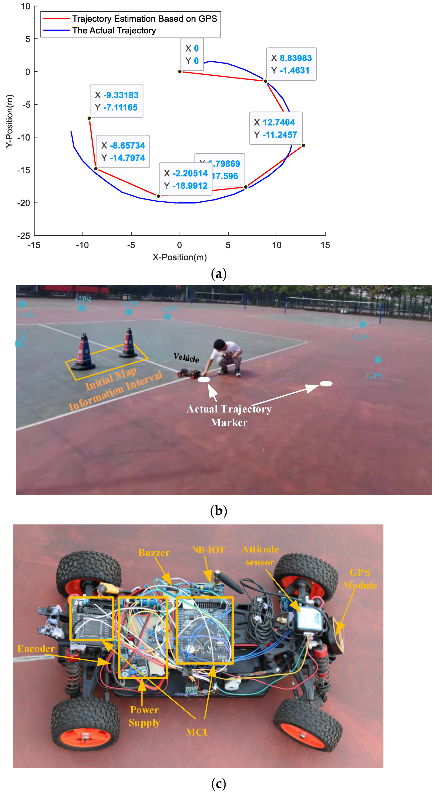
Figure 1. (a) Compared with the real trajectory of the target in our experiment, the trajectory estimated by GNSS−based discrete sparse points requires recovery. (b) Practical experiment diagram. (c) The structure of experiment hardware platform.
Electronics 11 03634 g001
Figure 2. Map constraint information figure.
Electronics 11 03634 g002
Figure 3. (a) The trajectory recovery of interval based forward propagation algorithm; (b) The trajectory recovery of interval based forward–backward propagation algorithm. The red dotted envelope always contains the yellow real trajectory.
Electronics 11 03634 g003
Figure 4. Integration of map constraint information. The rectangle boxes near the map constraint information are shrunken, compared with Figure 3b, which implies the effectiveness of the proposed FBP algorithm in fusing the map constraint information.
Electronics 11 03634 g004
Figure 5. The above figure shows the trajectory curves of the DR algorithm, Kalman filter algorithm, and FBP algorithm without integrated map constraint information, and the actual trajectory curves of our vehicle.
Electronics 11 03634 g005
Figure 6. The above figure shows the error and mean square error between the DR algorithm and Kalman filter algorithm without integrated map constraint information and the actual trajectory curve, and the error and mean square error between the FBP algorithm and the actual trajectory curve.
Electronics 11 03634 g006
Figure 7. The above figure shows the actual trajectory curve of the vehicle, as well as the DR algorithm trajectory curve, Kalman filter trajectory curve, and FBP trajectory curve integrated with map constraint information.
Electronics 11 03634 g007
Figure 8. The above figure shows the error and mean square error between the trajectory of the DR algorithm, Kalman filter algorithm, and FBP algorithm integrated with map constraint information and the actual trajectory curve respectively.
Electronics 11 03634 g008
Table 1. Notations.
Table 1. Notations.
NotationDescription
θ ( t ) The yaw angle of the vehicle at t
v ( t ) The velocity of the vehicle at t
a x ( t ) The acceleration of the vehicle in the x direction at t
a y ( t ) The acceleration of the vehicle in the y direction at t
S x ( t ) The displacement of the vehicle in the x direction at t
S y ( t ) The displacement of the vehicle in the y direction at t
τ The sampling interval of vehicle sensor data
x ( k ) The Kalman filter state in time slot k
u ( k ) The Kalman filter system control value in time slot k
w ( k ) The process noise in time slot k
z ( k ) The system measurements in time slot k
y ( k ) The measurement noise in time slot k
A The Kalman filter state transition matrix
B The Kalman filter control input matrix
H The Kalman filter state observation matrix
x ( t ) The trajectory coordinates of the vehicle at t
[ x ] ( t ) The trajectory interval based forward propagation of the vehicles at t
[ x ] ( t ) The vehicle’s trajectory based on FBP of the at t
[ v ] ( t ) The velocity interval of the vehicle at t
[ θ ] ( t ) The yaw angle interval of the vehicle at t
[ a ] ( t ) The acceleration interval of the vehicle at t
[ S ] ( t ) The trajectory interval of the vehicle at t
k ¯ The sampling points of the sensor between two GNSS coordinate points of the vehicle
x t r ( t ) The calculated trajectory coordinates of vehicle at t
a r e a ( t ) The trajectory interval area of vehicle at t
[ x m ] ( t ) The vehicle’s trajectory interval obtained by the FBP algorithm integrated map constraint information at t
[ M a p c ] Map constraint information in a road network
t m The timestamp of map constraint information occurrence
Table 2. Interval area size and computing cost.
AccuracyInterval-Based Forward Propagation AlgorithmInterval-Based Forward–Backward Propagation AlgorithmFBP Algorithm Integrated GNSS Information
The Total Area of Interval2938.34 m21648.82 m21441.16 m2
Interval Area Average48.17 m227.02 m223.63 m2
Computing Cost of The Program0.0334681 s0.0331482 s0.034207 s
Publisher’s Note: MDPI stays neutral with regard to jurisdictional claims in published maps and institutional affiliations.