Article

Hierarchical Clustering-Based Image Retrieval for Indoor Visual Localization

1
School of Computer Science and Technology, Changchun University of Science and Technology, Changchun 130022, China
2
Communication Research Center, Harbin Institute of Technology, Harbin 150080, China
*
Author to whom correspondence should be addressed.
Electronics 2022, 11(21), 3609; https://doi.org/10.3390/electronics11213609
Submission received: 6 October 2022 / Revised: 27 October 2022 / Accepted: 31 October 2022 / Published: 4 November 2022
(This article belongs to the Special Issue Design, Dynamics and Control of Robots)

Abstract

:
Visual localization is employed for indoor navigation and embedded in various applications, such as augmented reality and mixed reality. Image retrieval and geometrical measurement are the primary steps in visual localization, and the key to improving localization efficiency is to reduce the time consumption of the image retrieval. Therefore, a hierarchical clustering-based image-retrieval method is proposed to hierarchically organize an off-line image database, resulting in control of the time consumption of image retrieval within a reasonable range. The image database is hierarchically organized by two stages: scene-level clustering and sub-scene-level clustering. In scene-level clustering, an improved cumulative sum algorithm is proposed to detect change points and then group images by global features. On the basis of scene-level clustering, a feature tracking-based method is introduced to further group images into sub-scene-level clusters. An image retrieval algorithm with a backtracking mechanism is designed and applied for visual localization. In addition, a weighted KNN-based visual localization method is presented, and the estimated query position is solved by the Armijo–Goldstein algorithm. Experimental results indicate that the running time of image retrieval does not linearly increase with the size of image databases, which is beneficial to improving localization efficiency.

1. Introduction

With the development of communication technology, smart mobile terminals, such as smartphones and tablet personal computers, have become indispensable in modern society. Various applications on smart mobile terminals bring convenience to many aspects of people’s lives, and one example is navigation applications. The Global Navigation Satellite System (GNSS) allows individuals to acquire position information at any moment in outdoor environments [1,2,3,4]. Navigation and positioning services play crucial roles in public traffic, maritime transportation, and aviation flight. As the interior environments of buildings become increasingly complex, demands for indoor position services continue to rise. However, due to the shielding effect of structures, signals of the Global Navigation Satellite System are incapable of penetrating buildings, leading to users not being able to obtain reliable position services by the GNSS. Therefore, a stable and efficient indoor localization method independent of satellite signals has become a research hotspot in late years. Numerous daily activities can benefit from indoor localization technologies, such as shopping in large malls, finding books in libraries, and planning routes in railway stations and airports.
Many signal-based localization technologies have been investigated for querying indoor position information, such as WiFi-based [5,6], Bluetooth-based [7,8], and UWB-based [9,10,11] methods. All these methods, however, require investments in localization infrastructures. For example, WiFi-based approaches demand that a mobile terminal should receive signals transmitted by more than one access point [12,13]. Generally, more densely distributed access points contribute to improving the accuracy of localization systems. Similar to WiFi-based methods, high-density base stations must be deployed in indoor environments for Bluetooth-based and UWB-based localization systems. For the implementation of indoor localization, cost investments restrict the development of signal-based systems. By contrast, visual-based localization achieves high accuracy with hardly any infrastructure.
Another category of indoor localization approaches are those which estimate users’ positions iteratively by Inertial Measurement Unit (IMU) [14,15]. However, IMU-based systems are prone to cumulative errors accompanied by position iterative estimation, especially for a long trajectory. In addition, since IMU-based methods cannot determine the absolute positions of devices, these methods are generally combined with other localization technologies [16,17,18]. Different from IMU-based methods, visual localization could achieve either absolute position estimation or relative position estimation [19].
Visual localization aims at estimating the position of a camera (i.e., the query camera) mounted on a smart mobile terminal by image retrieval and geometrical measurement. Specifically, visual localization is usually implemented in known environments in which visual features are collected and stored as database images in the off-line stage [20]. In the on-line stage, a user captures query images by the query camera, and then the images are uploaded to the server. In the process of position estimation, the matched database images are retrieved on the server, and the positions of query images are calculated by localization algorithms. High accuracy and efficiency of image retrieval guarantee the performance of the entire localization system. The typical technology is Content-Based Image Retrieval (CBIR), the core of which is finding the most similar database images as the query image based on visual features. However, the retrieval task is challenging, because the number of database images is large, and there is no feasible strategy to organize the images in the database.
Therefore, in this paper, a hierarchical clustering-based image retrieval algorithm is proposed to organize database images, and an image retrieval strategy is investigated to improve retrieval efficiency. Moreover, a visual localization method is presented based on the Armijo–Goldstein principle. The main contributions of this paper are summarized as follows:
(1)
A global feature-based image clustering algorithm is proposed, in which the change-point detection method is adopted to identify which database images are captured in the same indoor scene. By this means, images captured in the same scene are clustered in a group, which achieves scene-level image clustering.
(2)
A local feature-based image clustering algorithm is presented, in which feature tracking is employed to further group the images that are in one scene-level cluster, by which means database images are grouped into sub-scene-level clusters.
(3)
A hierarchical clustering-based image retrieval algorithm is introduced, and visual localization is achieved based on the Armijo–Goldstein principle.
The remainder of this paper is organized as follows: Related work is reviewed in Section 1. Section 2 and Section 4 investigate the image clustering algorithms based on change-point detection and feature tracking, respectively. In addition, image retrieval and visual localization are explored in Section 4. In Section 5, the performances of the image retrieval and visual localization are evaluated. A discussion of the experimental results is presented in Section 6, and conclusions are drawn in the last section.

2. Related Works

Computer vision is a field of artificial intelligence that plays an essential role in widespread applications such as object tracking, object detection, image classification, and image retrieval [21,22,23,24]. The use of computer vision for pedestrian visual localization began in 2006, and then a typical framework of visual localization was determined [25,26]. Specifically, geo-tagged images are acquired as database images in the off-line stage, and then the position of the query image is estimated based on database images by image retrieval and geometrical measurement.
Recently, many studies have focused on visual localization, either in indoor or outdoor environments, with almost the same technical route [27,28,29]. The users’ positions are always estimated by query images in the condition of known or unknown camera-intrinsic parameters. One advantage of indoor visual localization is that the interior scenes of buildings can be reconstructed by mapping equipment [30]. Thus, compared with other positioning approaches, the vision-based methods provide users with more indoor-detail information and a better service experience [31]. Indoor visual localization contains three key technologies, which include: (1) 3D indoor mapping on the off-line stage (including database image acquisition), (2) image retrieval in the database, and (3) position estimation of the query camera. Image retrieval for visual localization can usually be divided into two phases: coarse retrieval and fine retrieval [32]. Specifically, global features on images can be utilized to achieve coarse image retrieval, and local features are appropriate for fine retrieval, resulting in obtaining the matched database image with the query image.
Colors, textures, and shapes are essential information to describe the global features of an image. Various global features, such as color moments, HSV histograms, wavelet transforms, and Gabor wavelet transforms, are extracted from images and used in the CBIR system [33,34]. Generally, more than one feature is selected to form a high-dimensional feature vector in order to overcome the limitations of a single feature. However, high-dimensional feature vectors would bring a heavy burden in measuring the similarity of images. Based on Gabor features, a global feature named Gist was proposed by Oliva et al., designed for scene recognition [35]. Gist features have already been widely used in indoor image retrieval and have achieved some remarkable results, which indicate that Gist features have the potential to address the image retrieval problem in visual localization [36,37].
Compared with global visual feature-based image retrieval technologies, local features are more suitable for fine image retrieval (i.e., finding the most similar database image with the query image). In recent years, research on local feature extraction has attracted much attention. Speeded Up Robust Features (SURF) [38] and Scale-Invariant Feature Transform (SIFT) [39] are the most widely used local features in the fields of object recognition, image stitch, visual tracking, and so on. For a visual localization system, local features are both applied to image retrieval and position estimation. Visual features employed in localization perform well in image similarity measuring and users’ position estimating. An efficient alternative feature (i.e., Oriented FAST and Rotated BRIEF, ORB) to SIFT or SURF was proposed by Rublee et al., which has been widely used in visual SLAM and has achieved promising results [40,41]. Based on existing literature and research, ORB features, utilizing fast key points and described by BRIEF descriptors, are also good at content-based image retrieval [42,43].
Most researchers of visual localization focus on position estimation algorithms, such as the authors of [29,44,45], but few of them pay attention to image retrieval in the localization system, much less to off-line image database organization. A typical hierarchical indexing scheme is proposed in [46], but only coarse retrieval is presented, and the best-matched database image cannot be found by this scheme. A well-organized image database contributes to improving the accuracy and efficiency of a localization system. In other words, a scalable image retrieval method is desired to fit different sizes of the database of the indoor localization system. Specifically, the search time of a scalable image system should not increase linearly with the number of database images, so that the response time of retrieval can be limited within a reasonable range. Therefore, aiming at the demand for visual localization, a database image hierarchical clustering method based on change-point detection and feature tracking is investigated in this paper. With the results of image retrieval, visual localization is executed to estimate users’ positions.
Visual localization in indoor environments has received widespread attention in recent years due to its extensive applications, such as the mobile museum tourist guide [47] and in-building emergency response [48]. Visual localization is also called image-based localization, in which images are employed as practical signals for localization [49]. Strictly speaking, visual localization is one of the fingerprinting-based localization methods, since images captured at known locations (i.e., database images) serve as fingerprints for position estimation. By image retrieval, the most similar database images as the query image are selected as fingerprints to calculate the query positions [50]. The majority of recent visual localization works focus on position estimation in the condition of known camera-intrinsic parameters by projective geometry [51,52,53]. However, the internal parameters of different cameras are not easy to obtain in practical localization scenarios. Therefore, research on image retrieval-based visual localization is crucial and necessary.
Only a limited number of works concentrate on image retrieval-based visual localization without camera calibration parameters. A representative work is the TUM indoor navigation system, in which the nearest neighbor (NN) method is employed for localization (i.e., the position attached to the most similar database image is identified as the query position) [49]. In many fingerprinting-based localization applications, finding the nearest neighbor to the query is regarded as an effective way to acquire the query position [54,55]. However, nearest neighbor-based visual localization may have a significant positioning error in some situations. For example, the query position is far from the fingerprint location when there are common objects visible in both the query image and the fingerprint image, which leads to accuracy degradation due to the improper nearest neighbor being selected to participate in the position calculation. To solve this problem, the K-nearest neighbor (KNN) method is applied in fingerprinting-based localization [56,57]. The KNN method selects the K-nearest fingerprint images and takes the average of their position coordinates as the estimated query position, avoiding the contingency of taking the nearest fingerprint image [58]. It is worth noting that each nearest neighbor in the KNN method has an equal contribution to the position estimation, which is unreasonable, because the average of nearest neighbor positions is hardly in accordance with the query position. More rational thinking is that the nearest neighbor with more similarity to the query is assigned a larger weight for the KNN method. Therefore, a weighted KNN (WKNN) method is presented in this paper to solve the estimated position of the query, taking full consideration of image similarities.

3. Image Clustering Based on Change-Point Detection in Global Features

A typical indoor visual localization system contains two stages: an on-line stage and an off-line stage, as shown in Figure 1. In the off-line stage, images are captured by the database camera mounted on the mapping equipment, and poses of the equipment are recorded simultaneously. In order to construct an indoor 3D map, Microsoft Kinects and laser scanners are also mounted on the mapping equipment [19]. An off-line database should be generated before the implementation of visual localization. It contains the essential elements for localization: database images, poses (including orientations and positions) of the equipment, and indoor 3D maps.
In the on-line stage, a query image is captured by the user and uploaded to the server by wireless networks. The most similar database images (i.e., matched database images) to the query image are retrieved based on the visual features extracted from the images. Then, the position of the matched database images can be employed to estimate the position of the query camera. Accuracy and efficiency of image retrieval are the key to ensuring the good performance of the system. A hierarchical clustering-based image retrieval is proposed in this paper and mainly discussed in the following.

3.1. Feature Extraction and Pre-Processing

Gist is a scene-centered global feature commonly used in scene classification and place recognition. In this paper, Gist features are employed for scene-level image clustering by change-point detection. In the implementation of creating the off-line database (i.e., an indoor 3D map), database images are successively acquired by the mapping equipment in the same indoor scene, and visual features of these images have high correlations. In contrast, when the mapping equipment moves from one indoor scene to another, the correlations of the captured database images are weakened. Based on this characteristic of database images, change-points can be detected in the global features extracted from the images, resulting in the database images captured in the same indoor scene being grouped in a cluster, which achieves scene-level image clustering. The center of each cluster represents the main features of the scene, so that the query image orderly retrieves each cluster by measuring the difference between the query image and the centers of database image clusters.
To reduce computation complexity, visual feature vectors should keep a low dimension, so an image is regarded as a whole from which global features are extracted. For each query image and database image, a three-scale ( S G = 1 ,   2 ,   3 ) and six-orientation ( O G = 0 ° , 60 ° , 120 ° , 180 ° , 240 ° , 300 ° ) filters are used in Gist feature extraction, where S G and O G present spatial scale levels and cardinal orientations, respectively. During feature extraction, images are processed via convolution operation by multi-channel filters, and then the filtering results are connected to achieve 18 ( 3 × 6 = 18 ) dimensional feature vectors. G Q and G D denote global features extracted from the query image and database images, respectively. Figure 2 shows examples of database images and the corresponding spectrograms of Gist features.
For visual localization, the query image is captured by a hand-held smartphone, and image retrieval is completed on the server side after the image is uploaded to the server. The Gist feature vectors of the query image and database images are separately presented by G Q = g Q 1 ,   g Q p ,   g Q 18 and G D i = g D i ,   1 ,   ,   g D i ,   q ,   ,   g D i ,   18 , where g Q p and g D i ,   q denote the p-th and q-th elements in the feature vector G Q and G D ( 1 p 18 and 1 q 18 ), and i is the index of database images. The database images successively acquired in the same indoor scene have high visual correlations. However, once the mapping equipment switches to another scene, the correlations subsequently decrease. The change-point detection method is employed, aiming to detect the change in the visual correlations between database images, and further, the database images captured in the same scene are grouped into one cluster.
If there are in total n D database images in the indoor 3D map (i.e., the off-line database), n D features can be extracted from the database images. Therefore, a Gist feature matrix M G can be obtained by organizing all feature vectors:
M G = g D 1 ,   1 g D 1 ,   q g D 1 ,   18 g D i ,   1 g D i ,   q g D i ,   18 g D n D ,   1 g D n D ,   q g D n D ,   18
To achieve scene-level clustering, change-point detection acts on each column in M G . Specifically, change points should be separately detected in the column vector M G q = g D 1 ,   q ,   ,   g D i ,   q ,   g D n D ,   q T , where 1 q 18 . On account of noise existing in feature extractions, a pre-process should be applied on Gist features. Therefore, the Kalman filter and the Kalman smoother are used in this paper to recover the visual correlations of database images acquired in the same scene. The purpose of feature pre-processing is to avoid false detection caused by noise, namely, detecting a change point without a scene change.
If the state variable and the observed variable of features are separately set as x i and y i , the system equation is:
x i = Φ i 1 x i 1 + w i y i = H i x i + v i
where Φ i 1 and H i are gain matrixes. The process noise w i and measurement noise v i satisfy:
p w i ~ N 0 Γ
p v i ~ N 0 Σ
where N μ σ denotes a normal distribution with the variance σ and the expectation μ . The initial value of x i is defined as x 0 = μ 0 + u , where p x 1 satisfies N μ 0 V 0 and p u satisfies N 0 V 0 [59].
The discrete Kalman filter estimates the process state by feedback control. The typical Kalman filter can be divided into two parts, namely, the time-update part and the measurement-update part. In the time-update part, to obtain the prior estimate of the next time state, the Kalman filter calculates the state variables of the current time and the estimated covariance of errors by the update equation. In the measurement-update section, new observations are combined with prior estimates to obtain more reasonable posterior estimates by feedback operations.
When using a discrete Kalman filter to process data, the previous error covariance P i before system updating should be calculated by:
P i = Φ i 1 V i 1 Φ i 1 T + Γ
where V i 1 is the error covariance after system updating. The Kalman gain K i can be further calculated based on the error covariance P i by:
K i = P i H i T H i P i H i T + Σ 1
According to the un-updated error covariance and Kalman gain, the error covariance can be updated by:
V i = I K i H P i
Then, the posterior estimates of the state variable x ^ i (updated value) can be obtained by:
x ^ i = x ^ i + K i y i H i x ^ i
where the prior estimate of the state variable can be obtained by the extrapolation formula:
x ^ i = Φ i 1 x ^ i 1
System iterative updates can be achieved by Equations (7) and (8), which achieves Kalman estimation for all measured values.
After Kalman filtering, Kalman smoothing needs to be performed on the filtering results. According to the Kalman backward smoothing equations, the smoothed estimate x ^ i of the state variable and the smoothed error covariance V i can be obtained by:
x ^ i = x ^ i + J i x ^ i + 1 + Φ i x ^ i
V i = V i + J i V i + 1 P i J i T
where J i is defined as:
J i = V i Φ i T P i 1
The optimized vector M K q = g K 1 ,   q ,   ,   g K i ,   q ,   ,   g K n D ,   q T can be obtained based on the Kalman smoother by Equations (9) and (10), where g K i ,   q is the feature element after Kalman filtering and smoothing. n D is the total number of database images, and q is the index of feature vectors. As 18 Gist features are extracted from a database image, the range of q satisfies 1 q 18 .

3.2. Image Clustering Based on CUSUM Change-Point Detection

Change-point detection on Gist features of database images is to group the successive database images between change points into one cluster, thereby realizing scene-level database image clustering. For a random process that occurs in chronological order, change-point detection is detecting whether the distribution or distribution parameters of random elements in the process suddenly change at a certain moment. In this paper, change points are detected on the Gist features extracted from successive database images, thereby finding the database image in which the indoor scene changes. When the change-point detection on all Gist features is completed, the database images between the change points are grouped into one cluster, and these images are deemed to be acquired in the same scene (e.g., office, kitchen, corridor, etc.). The rationality of the algorithm is that when constructing the off-line 3D indoor map, the database camera successively captures the database images in the same scene. Therefore, the obtained database images are successive in the same scene. That is, the Gist features of the database images have a certain correlation. Once the indoor scene changes, it is possible to perceive the occurrence of such a change by detecting the change points of the Gist features.
The CUSUM (Cumulative Sum) algorithm used for change-point detection in this paper is an anomaly detection method commonly used in industrial fields. The CUSUM algorithm is generally applied to all data to detect change points. For data located at a certain position in the sequence, other data in front of and behind this position are used for change-point detection. However, such a detection method will undoubtedly increase the time overhead, especially as the amount of historical data becomes larger and larger with time, which will eventually cause excessive time overhead. Therefore, a sliding window is introduced to constrain the number of Gist features that need to be processed in change-point detection, as shown in Figure 3.
As shown in Figure 3, an 18-dimensional Gist feature vector can be extracted with different scales and directions for each database image. After Kalman filtering and smoothing, each Gist feature can be represented as g K i ,   q , where the superscript i indicates the index of database images, and the subscript q indicates the element position in a feature vector. For the Gist features extracted from different database images, if they are located in the same column q , the scales and orientations of these features are the same. In order to constrain the data size during change-point detection, a sliding window of the size ω is implemented in CUSUM change-point detection. Specifically, if the currently detected position is i , and the corresponding Gist feature is g K i ,   q , only the features in the sliding window are considered. That is to say, only the features between g K i w / 2 + 1 ,   q and g K i + w / 2 ,   q are detected. In addition, the change-point detection algorithm is only applied to the features that have the same scale and orientation. For different Gist feature sequences, such as M K 1 , , M K 17 , and M K 18 , they should be separately detected.
In the CUSUM change-point detection, considering the sequence of successively acquired database images is a time series, the acquisition time corresponds to the index of the database image in the sequence. Therefore, the change-point detection in this paper detects the position at which the change point appears in the image sequence. The CUSUM change-point detection algorithm estimates the position of the change point in the sequence by calculating the parameter models of Gist feature sequences. The probability density function is employed to determine the positions of change points in a Gist feature sequence. For a Gist feature sequence M K q = g K 1 ,   q ,   ,   g K i ,   q ,   ,   g K n D ,   q T , a sub-sequence M W q = g K i w / 2 + 1 ,   q ,   ,   g K i ,   q ,   ,   g K i + w / 2 ,   q T within the sliding window can be obtained, and change-point detection only acts on feature element g K i ,   q . According to the position of g K i ,   q , sequence M W q can be divided into two sub-sequences: M W A = g K i w / 2 + 1 ,   q ,   , g K i ,   q T and M W B = g K i + 1 ,   q ,   ,   g K i + w / 2 ,   q T .
According to the Neyman–Person lemma, the core of CUSUM change-point detection can be considered a hypothesis-test problem. For this hypothesis test, the null hypothesis H0 is the case that the feature element is not a change point. In this case, the indoor scene corresponding to the database image does not change. In contrast to the null hypothesis, alternative hypothesis H1 indicates the scene changes, in which case the feature element does not satisfy the previous parameter model. The purpose of the CUSUM algorithm is to monitor and determine at which point hypothesis H1 switches to H0 in the feature sequence.
For sub-sequences M W A and M W B in the sliding window, it is considered that the feature elements in the sequences are independent variables and subject to the normal distribution, so two parameter models, namely, parameter model A and parameter model B, can be obtained.
The probability density functions of the two parameter models are f A and f B which satisfy:
f A g K i ,   q ~ N μ A σ A
f B g K i ,   q ~ N μ B σ B
where μ A and μ B are the expectation and variance of the parameter model A. μ B and σ B are the expectation and variance of the parameter model B.
If the hypothesis test is applied to the feature elements in the sliding window, the probability density function under the null hypothesis H0 is f A , and the probability density function under the alternative hypothesis H1 is f B . Thus, a likelihood ratio function h i relating to g K i ,   q can be obtained by:
h i g K i ,   q = ln f B g K i ,   q / f A g K i ,   q
Based on the likelihood ratio function, a cumulative sum function can be defined as:
H i g K i ,   q = j = 1 i h i g K j ,   q = j = 1 i ln f B g K j ,   q / f A g K j ,   q
For the CUSUM algorithm, the position t c h of the change point can be calculated by a given threshold T c h :
t c h = inf i 1 :   H i min 1 k i H k T c h
According to the detection principle shown in (17), a threshold must be set in advance when employing the typical CUSUM algorithm for change-point detection. However, in many cases, it is difficult to determine the threshold for change-point detection due to the complexity and diversity of indoor scenes. Therefore, an improved cumulative sum change-point detection (ICSCD) algorithm is proposed to identify change points without a given threshold.
Since the probability density functions of the two sub-sequences in the sliding window are subject to a normal distribution, the likelihood ratio function can be expanded as:
h i g K i ,   q = ln f B g K i ,   q / f A g K i ,   q = ln exp g K i ,   q μ B 2 / 2 σ B 2 / 2 π σ B exp g K i ,   q μ A 2 / 2 σ A 2 / 2 π σ A
If the variances of parameter model A and parameter model B are considered identical (i.e., σ A = σ B = σ A B ), then the likelihood ratio function h i can be simplified as:
S L g K i ,   q = 2 μ A μ B g K i ,   q μ A 2 μ B 2 2 σ A B 2
The cumulative sum function of g K i ,   q in the proposed ICSCD algorithm is defined as:
H i g K i ,   q = j = 1 i h i g K i ,   q = j = 1 i 2 μ A μ B g K i ,   q μ A 2 μ B 2 2 σ A B 2
where expectations μ A and μ B corresponding to parameter models A and B can be calculated by:
μ A = 2 w k = i w / 2 + 1 i g K k ,   q
μ B = 2 w k = i + 1 i + w / 2 g K k ,   q
According to Equation (20), the cumulative sum function depends on three variables: the Gist feature element g K i ,   q detected as the change-point, the expectation μ A of parameter model A, and the expectation μ B of parameter model B. Therefore, the numerator of Equation (20) can be defined as a change-point detection function to monitor whether the indoor scene changes on the position i :
F C g K i ,   q = 2 μ A μ B g K i ,   q μ A 2 μ B 2
Depending on the above analysis, Gist feature sequences can be processed by the change-point detection function. The specific process is as follows: first, for the feature elements between w / 2 and n D w / 2 in the sliding window, the values of the change-point detection function need to be calculated, where w is the size of the window and n D is the total number of database images. Second, the peaks of the discrete values of function F C are detected, and the peaks correspond to the change points in feature sequences. More than one Gist feature sequence is extracted from the database images (18 feature sequences extracted in this paper, i.e., M K q , 1 q 18 ), and each feature sequence needs to be detected separately. Therefore, it is necessary to propose a strategy to integrate the detected change points from each feature sequence to find the images corresponding to indoor scene changes.
Since 18 Gist feature elements are extracted from each database image, an 18 × n D matrix containing change-point marks can be obtained for n D database images. Each mark in the matrix represents whether the Gist feature element on this position is a change point. Specifically, if the feature element in one position is detected as a change point, the value of the mark in this position is defined as 1. Otherwise, the value is defined as 0. As shown in Figure 4, a window with the size l w ( l w is an odd number, namely l w = 2 k w + 1 , and k w is a positive integer) slides on the matrix, and the values of the marks in the window are added up. The meaning of the accumulated value of the marks is the total number of change points in the window. If the accumulated value of the marks in the window exceeds a given threshold, the center of the window is considered the position of the change point.

4. Feature Tracking-Based Image Clustering, Hierarchical Retrieval and Visual Localization

Based on the proposed ICSCD algorithm, scene-level database image clustering can be achieved by global visual features of database images. However, in the implementation of database construction, there are usually too many database images acquired in the same indoor scene, which leads to excessive time overheads of image retrieval in the on-line stage. Therefore, the database images in the same scene-level cluster are further grouped to achieve sub-scene-level clustering. For sub-scene-level clustering, local visual features of images are employed. In the process of local feature tracking, if the change rate of the number of tracked features is below the given threshold, the database image is defined as a breakpoint image. The database images between the two breakpoint images are acquired in the same sub-scene, so the images between the breakpoints are grouped into one sub-cluster.

4.1. Image Clustering Based on KLT Feature Tracking

A database image can be described by the gray-level function I x I ,   y I ,   t , where x I ,   y I is the position of a pixel on the image, and t presents the time stamp. Since database images are successively acquired, time stamp t is equivalent to the image index. In addition, the interval of image acquisition is small, resulting in high visual correlations between database images, which is the precondition for using feature tracking for image breakpoint detection. When the database camera moves within a sub-scene, an overlap exists between the adjacent database images, and a certain number of local features on the images can be tracked. According to this characteristic of database images, a KLT (Kanade–Lucas–Tomasi) feature tracking-based image-clustering method is proposed in this section.
The features are continuously tracked between the two adjacent database images with index i and i + 1 by the KLT algorithm. Let Φ 1 denote an image cluster in the scene-level clustering results. In the off-line stage, the local visual features (i.e., ORB features) are extracted from images and stored in the database used in the sub-scene-level image clustering. Let L O i = l i 1 ,   ,   l i j ,   ,   l i n O T present an ORB feature matrix consisting of the vector l i j = l i j ,   1 ,   ,   l i j ,   k ,   ,   l i j ,   32   , where i is the index of the database image, j is the index of feature vectors, and k   1 k 32 is the index of elements in a feature vector. For each ORB feature extracted from an image, there is a feature vector (i.e., l i j ) and a position vector (i.e., p i j = x I i ,   j ,   y I i ,   j T ) corresponding to the ORB feature, where p i j is expressed in the image coordinate system.
To track features, a rectangular window on the image needs to be set whose length is 2 w K + 1 pixels and whose width is 2 h K + 1 pixels. Based on the assumptions of constant brightness, time continuity, and spatial consistency in the rectangular window, it is considered that the matching feature points on the database image satisfy the following relationship:
J x I i ,   j + d x ,   y I i ,   j + d y ,   i + 1 = I x I i ,   j ,   y I i ,   j ,   i
where I x I i ,   j ,   y I i ,   j ,   i is the gray value of the feature point located at x I i ,   j ,   y I i ,   j T on the i-th database image. For the next database image, J x I i ,   j + d x ,   y I i ,   j + d y ,   i + 1 is the gray value of the feature located at x I i ,   j + d x ,   y I i ,   j + d y T . d x and d y denote the displacement distances in the X and Y directions on the image, respectively. Equation (24) indicates that for the matching feature points on the database image, only the displacement changes occur on the adjacent images, and the magnitude of the gray values does not change. The core of feature tracking is to solve d x y = [ d x ,   d y ] T .
In order to obtain the displacement change, a sum of the squared intensity difference function is defined as:
ε d x y = x = x I i ,   j w K x I i ,   j + w K y = y I i ,   j h K y I i ,   j + h K I x ,   y ,   i J x + d x ,   y + d y ,   i + 1 2
Taking the derivative of the sum of the squared intensity difference function and setting it to zero, the optimal solution d x y * of the displacement can be obtained by:
ε d x y d x y = 2 x = x I i ,   j w K x I i ,   j + w K y = y I i ,   j h K y I i ,   j + h K I J · J x ,   J y = 0
where I x ,   y ,   i and J x + d x ,   y + d y ,   i + 1 are abbreviated to I and J , respectively.
Based on the Taylor formula, the first-order approximation of Equation (26) on 0 , 0 T can be obtained by:
ε d x y d x y 2 x = x I i ,   j w K x I i ,   j + w K y = y I i ,   j h K y I i ,   j + h K I J J x ,   J y d x y · J x ,   J y
Equation (27) can be further expressed as:
ε d x y d x y T 2 x = x I i ,   j w K x I i ,   j + w K y = y I i ,   j h K y I i ,   j + h K I x 2 I x I y I x I y I y 2 d x y H x y I x H x y I y
where I x , I y , and H x y are:
I x = I x ,   y ,   i x = I x + 1 ,   y ,   i I x 1 ,   y ,   i 2
I y = I x ,   y ,   i y = I x ,   y + 1 ,   i I x ,   y 1 ,   i 2
H x y = I x ,   y ,   i J x ,   y ,   i
Let Equation (28) be equal to zero, and the optimal solution d x y * can be obtained by:
d x y * = x = x I i ,   j w K x I i ,   j + w K y = y I i ,   j h K y I i ,   j + h K I x 2 I x I y I x I y I y 2 1 × x = x I i ,   j w K x I i ,   j + w K y = y I i ,   j h K y I i ,   j + h K H x y I x H x y I y
Initialization should be applied to database image set Φ 1 , which means that the first database image in the set Φ 1 is defined as a breakpoint. From the second database image in the set Φ 1 , the KLT algorithm is employed to track local features between the adjacent images. Let k denote the index of the breakpoint image, and then the number of tracked features can be presented by the vector n T = n T k + 1 ,   n T k + 2 , ,     n T k + k ,   , where n T k + k is the number of tracked features corresponding to the image with index k + k . To determine the position of the breakpoint image, a threshold is required to monitor the number of tracked features. For the database image with index k + k , the corresponding breakpoint image-detection threshold T T r k + k is defined as:
T T r k + k = w T r k j = k + 1 k + k n T j 1 n T j n T j
where w T r is the scale coefficient, and the change rate of the number of tracked features is r T r k + k = n T k + k 1 n T k + k / n T k + k .
According to the change rate r T r k + k and threshold T T r k + k , an image can be determined whether or not it is a breakpoint image. Specifically, if r T r k + k T T r k + k , the database image with index k + k is regarded as a breakpoint image, as shown in Figure 5. Breakpoint detection is applied to each scene-level clustering result, and then all breakpoint images in the database image set can be found. Database images between two breakpoint images and the front breakpoint image are grouped into one cluster, achieving the sub-scene-level image clustering. The feature vector of the breakpoint image of each cluster is the cluster center. That is, the feature vector of the first image in the cluster is the cluster center (as shown in Figure 5). In the i-th scene-level cluster, the center of the j-th sub-scene-level cluster can be denoted by L i j , which is an ORB feature vector.

4.2. Hierarchical Image Retrieval and Visual Localization

In the off-line stage, database images are hierarchically grouped, and a search tree with three layers is achieved: (1) the first layer contains centers of scene-level clusters, (2) the second layer consists of centers of sub-scene-level clusters, and (3) the third layer contains database images in sub-scene-level clusters. It should be noted that the center of the scene-level cluster is a global feature vector (i.e., a Gist feature vector), and the center of the sub-scene-level cluster is a local feature vector (i.e., an ORB feature vector). According to the results of hierarchical image clustering, a three-layer search tree can be organized. As shown in Figure 6, there are m clustering results in the first layer of the search tree, and each clustering result in the first layer, such as G C i , corresponds to more than one second-layer result (i.e., L i 1 ,   ,   L i n i ). In addition, the database images grouped into one sub-cluster are associated with the cluster center, such as L i n i . Based on the organized multi-layer search tree, a hierarchical clustering-based image retrieval (HCIR) algorithm is proposed for visual localization.
Based on the multi-layer search tree shown in Figure 6, hierarchical image retrieval is applied to find the most similar database image to the query image. In the on-line stage, global and local features are extracted from the query image and uploaded to the server by wireless networks. Then, the similarity between the query image and the centers of scene-level clusters can be defined as:
l S = G Q G C i
where G Q is the Gist feature vector extracted from the query image, and G C i   1 i m is a scene-level cluster center.
By measuring similarities between the global features of the query image and scene-level cluster centers, the scene-level clusters can be ranked. Then, the query image orderly retrieves each scene-level cluster. When the most similar scene-level cluster is found, the sub-scene-level clusters in that cluster should be sorted. Specifically, suppose a query image needs to find its most similar database image in the cluster G C i . In that case, local features extracted from the query image should be matched with each center of sub-scene-level clusters, i.e., L i 1 , , L i n i . The number of matched local features reflects the similarities between the query image and the sub-scene cluster centers. For the cluster G C i , sub-scene-level clusters are orderly retrieved by the query image. By this means, scene-level clusters and sub-scene-level clusters can be ranked based on visual similarities between the query image and cluster centers. According to the ranked clusters, local feature matching should be orderly executed between the query image and the database images in the third-layer clusters.
Let n m a t k s denote the number of matched features between the query image and the ks-th database image. Then, the feature matching ratio can be defined as:
s L k S = n m a t k S / n Q
where 0 s L k S 1 and n Q is the number of the ORB features extracted from the query image.
The matched features are used in visual localization, and more matched features contribute to improving localization accuracy. In addition, more matched features indicate that the query image is closer to the database image. Therefore, the best-matched database image with the query image is desired to estimate the position of the query camera in visual localization. Since database images are successively captured, when the query image is matched with database images, the trend of feature-matching ratios presents regularity. Specifically, if the query image and the database image are acquired in the same scene, when the query image is orderly matched with the database image, the trend of matching ratios first increases and then decreases. The reason is that when the query image gradually approaches the best-matched database image, the matching ratios will gradually increase until the ratio reaches a maximum value. At this position, the database image is best matched with the query image. After that, the distance between the query image and the best-matched database image gradually increases, and the matching ratios decrease. Based on the above analysis, if the maximum value of the matching ratios can be found, the best-matched database image can be determined. The method of finding the best-matched database image is named the maximum similarity method in this paper.
To find the best-matched database image, a sliding window should be set as shown in Figure 7. In a sliding window with the size w F + 1 , the index of the image at the center is k S . If the image with the index k S is determined as the best-matched database image, the matching ratio s L k S of the database image should satisfy:
s L k S s L k S 1 s L k S w F / 2 r m a t s L k S s L k S + 1 s L k S + w F / 2 r m a t
where r m a t 0 ,   1 is the threshold of the matching ratio. The threshold ensures that the database images and the query image are captured in the same scene.
According to the ranking results of the scene-level and sub-scene-level clusters, the query image orderly retrieves each cluster until it finds the best-matched database image. A situation may arise in image retrieval. That is, the query image is matched with all the database images of the most similar scene-level cluster, but the best-matched database image is still not found. Therefore, a backtracking mechanism is introduced in the proposed hierarchical retrieval. In this mechanism, when the best-matched database image with the query image cannot be found after comparing with all the database images in the scene-level cluster, the query image will return to the top of the search tree and continue to retrieve the next cluster according to the ranking results, and so on. In the worst case, all database images are compared with the query image, and the best-matched database image is still not found. Then, the database image with the maximal matching ratio is determined as the best-matched image, but in this case, the distance between the query image and the database image is perhaps far.
By the proposed HCIR algorithm, the best-matched database image with the query image can be found in the database, and the best-matched database image has the following characteristics: (1) the database image is captured in the same scene as the query image; (2) there are a number of matching feature points between the query image and the database image. If the query image is considered to be coincident with the position of the best-matched database image, a preliminary position estimation of the query camera can be achieved. However, this position estimation method is subject to the acquisition density of the database images. In order to improve the localization accuracy, the top-K best-matched database images are selected and used to estimate the position of the query image.

4.3. Visual Localization Based on Weighted KNN Method and Armijo–Goldstein Algorithm

In practical localization scenarios, images with higher similarity tend to be closer. Namely, the more similar the query image and the database image are, the smaller the distance between the two images is. With this thinking, a weighted KNN-based visual localization method is proposed, by which the matched database image with a higher similarity is assigned a larger weight. The similarities between images are evaluated by the number of matched feature points in visual localization.
The top-K best-matched database images with the query image are regarded as the nearest neighbors to estimate the query position, so the localization error function can be defined as:
f e p Q = i = 1 K w i p Q p D i
where p Q is the estimated position of the query image, and p D i   1 i K is the position of the database image. w i is the weight that can be calculated by:
w i = n m a t i j = 1 K n m a t j , i = 1 ,   ,   K
where n m a t i denotes the number of matched feature points between the query image and the database image.
For Equation (37), the Armijo–Goldstein algorithm is used to solve the estimated position of the query image (i.e., the position of the query camera) [60]. The gradient vector of f e at p Q k = x Q k ,   y Q k is:
g = f e x x Q k ,   y Q k , f e y x Q k ,   y Q k
According to the gradient vector, the search direction s can be further determined by s = g . The procedure of visual positioning can be treated as a line search, as shown in Algorithm 1. The count flag s k , index t m , maximum number of iterations k max (=5000), threshold σ r (= 10 3 ), amplification coefficient γ (=0.4), and step length d (=0.01) are set as inputs.
Algorithm 1: Visual localization based on Armijo–Goldstein algorithm
Input:
localization error function f e , count flag s k , index t m , maximum number of iterations k max , threshold σ r , amplification coefficient γ , and step length d
Output:
estimated position p Q of the query camera
Step 1:
set initial values s k = 0 and t m = 0 ;
Step 2:
calculate the norm of the direction vector by s n = s
if s n > σ r , turn to Step 3,
else turn to Step 5;
Step 3:
if f e p Q k + d t m s < f e p Q k + γ d t m g 1 s , then s k = t m and turn to Step 4,
else  t m t m + 1 and turn to Step 4;
Step 4:
update the position of the query camera by p Q k + 1 = p Q k + d s k s and k k + 1 ,
if  k k max , then turn to Step 5,
else turn to Step 1;
Step 5:
determine the position of the query camera by p Q k , i.e., p Q = p Q k .
With the visual localization method, the estimated position p Q of the query camera can be achieved by solving the line search problem, in which the similarity between the query image and the database images is reflected by the weight w i . Therefore, the estimated position of the query camera is closer to the database images with high similarity.
In summary, visual localization is achieved by two steps: hierarchical clustering-based image retrieval and query camera position estimation. Since the proposed visual localization method dispenses with camera calibration, it can be widely used in different application scenarios and applied to various smart mobile terminals.

4.4. Performance Analysis on Hierarchical Image Retrieval

The proposed HCIR algorithm aims to decrease the on-line search time by sacrificing the processing time of off-line image clustering. Still, database image clustering is continuously efficacious, which means that once the database image clustering is completed, the results of clustering can be repeatedly applied to on-line image retrieval. The proposed algorithm in this paper achieves multi-layer image clustering. Compared with the single-layer clustering algorithm (i.e., only scene-level image clustering is implemented), an advantage of the proposed algorithm is that the search time does not scale up for the database size. Next, the computation performance of the proposed algorithm and the single-layer clustering-based algorithm will be analyzed in detail. For clustering-based image retrieval, on-line time consumptions contain five parts: (1) the time t G to extract the global features of the query image, (2) the time t L to extract the local features of the query image, (3) the time t G S to measure the similarity of global features between the query image and database images, (4) the time t L M to match the local features between the query image and database images, and (5) the time t F S to sort database images according to their similarity to the query image. If there are n L 1 scene-level clusters in the first layer, and each cluster contains n L 2 sub-scene-level clusters, the average running time T S L of the single-layer clustering-based retrieval algorithm is:
T S L = t G + t L + n L 1 t G S + t F S + k L 1 m L 1 t L M + 1 + m L 1 2 t L M
where k L 1 is the number of scene-level clusters that have been retrieved when the backtracking mechanism is enabled, and m L 1 and m L 2 are the number of database images in the scene-level cluster and the sub-scene-level cluster, separately.
The average running time T M L of the proposed image retrieval algorithm is:
T M L = t G + t L + n L 1 t G S + 2 t F S + k L 1 n L 1 t L M + k L 2 m L 2 t L M + n L 2 t L M + 1 + m L 2 2 t L M = t G + t L + n L 1 t G S + 2 t F S + k L 1 n L 1 t L M + k L 2 m L 2 + n L 2 t L M + 1 + m L 2 2 t L M
where k L 2 is the image number of sub-scene-level clusters that have been retrieved when the backtracking mechanism is enabled. In this case, if the query image does not obtain a matched database image after retrieving a complete scene-level and sub-scene-level clustering result, the time consumption of the two processes is n L 1 t L M and n L 2 t L M , respectively. The total number m t o t a l of database images satisfies: m t o t a l = n L 1 m L 1 and m L 1 = n L 2 m L 2 , where m L 1 and m L 2 are image numbers of the scene-level cluster and the sub-scene-level cluster, respectively.
For single-layer clustering-based image retrieval, database images are orderly matched with the query, so the average retrieving time of an image cluster is 1 + m L 1 t L M / 2 . Similarly, for the proposed algorithm, the average retrieval time of a sub-scene-level cluster is 1 + m L 2 t L M / 2 . According to the principle of multi-layer clustering, the image number m L 1 is far more than m L 2 . As a result, the query image could find its matched database image in a cluster using less time for the proposed HCIR algorithm. The proposed algorithm has three additional time overheads (i.e., the time k L 2 m L 2 t L M to retrieve the k L 2 results, the time n L 2 t L M to match features, and the time t F S to sort database images) compared with the single-layer clustering algorithm. However, in practical applications, feature-sorting time is much shorter than feature-matching time, and in most cases, the value of k L 2 is zero. Therefore, the sum of the retrieval time 1 + m L 2 t L M and the feature-matching time n L 2 t L M is still less than the retrieval time 1 + m L 1 t L M / 2 . If the best-matched database image can be obtained without trigging the backtracking mechanism (i.e., k L 1 = k L 2 = 0 ), the difference Δ t in time consumption between the single-layer clustering algorithm and the proposed algorithm is:
Δ t = m L 1 m L 2 2 n L 2 2 t L M t F S
Compared with the multi-layer clustering-based algorithm, there are more database images contained in the cluster for the single-layer clustering-based algorithms. Moreover, as a multi-layer clustering-based algorithm, the proposed HCIR algorithm has priorities for retrieving the image clusters with high similarities to the query, so that the matched image can be found by searching fewer database images. Therefore, the structure of a multi-layer search tree is beneficial in reducing retrieval time consumption.

5. Experimental Results and Discussion

In this section, the hierarchical clustering-based image retrieval is implemented, and the computation performance of the retrieval algorithm is analyzed. In addition, the position accuracy of the visual localization is evaluated.

5.1. Experimental Results of Database Image-Clustering Algorithm

Two image databases (namely, the KTH image database [61] and the HIT-TUM image database) were used to evaluate the performance of the proposed algorithm. The images in the HIT-TUM database were acquired from the Harbin Institute of Technology and the Technical University of Munich. Each database contains 400 images captured in 10 different indoor scenes, such as an office, a corridor, a restaurant, and so on. All data processing was run on MATLAB 2018A with an Intel Core i7 CPU and 8GB RAM. Randomly selected example images in the databases are shown in Figure 8. It is worth noting that images in the databases are successively captured in indoor scenes, so the visual features extracted from the images captured in the same indoor scene have high correlations.
For scene-level image clustering, database images are grouped by their global features based on the CUSUM change-point detection. The results of the scene-level clustering guide the query image to retrieve the clusters that are similar to the query. Therefore, the performance of database image clustering affects the efficiency of the image retrieval system. For an image retrieval system, the efficiency of the retrieval algorithm is reflected in two aspects: the number of searched database images and the time consumption of the image retrieval. Generally, the fewer database images are searched, the less time retrieval takes.
In the same indoor scene, as the database images are successively captured, the Gist features extracted from these images have high correlations. Taking advantage of the correlations, scene-level clustering of database images can be achieved. However, the noise generated in feature extraction affects the correlation of the features. Therefore, the original Gist features of database images need to be pre-processed (including Kalman filtering and Kalman smoothing) to restore the correlation of image features. For a database image, Gist features can be extracted according to different scales and directions. In this paper, Gist features are extracted at three scales and six directions, so 18 3 × 6 = 18 feature elements are extracted from each image. That is, the Gist feature vector of each image contains 18 feature elements. Figure 9 shows an example of the Gist feature pre-processing result of a database image, including the original Gist feature values, Kalman filtering results, and Kalman smoothing results. It can be found from Figure 9 that the correlation between original feature values is not evident due to the influence of noise. In contrast, by Kalman filtering, noise is effectively suppressed, and the correlations between features are restored. According to Kalman filtering results, more obvious correlations can be obtained by further Kalman smoothing of Gist features. The pre-processing of features recovers the correlations of global features of database images, which is beneficial to scene-level clustering.
Scene-level database image clustering is achieved by detecting the change-points in Gist feature sequences. When image retrieval is executed in the results of scene-level clustering, according to the similarity of the global features, the query image will preferentially search the database image clusters with a higher similarity. Therefore, if all database images in the same scene are grouped into one cluster, the query image captured in this scene can find its matched database images in this cluster. In contrast, if a database image captured in a certain scene is falsely grouped into other clusters, this database image cannot be retrieved when the query searches the right cluster. Depending on the above analysis, the core of the proposed algorithm is that the database images in the same scene are grouped into one cluster as much as possible.
To analyze the performance of the proposed algorithm, scene-level image clustering is executed, and confusion matrices are employed to evaluate clustering accuracy. The confusion matrices of the results of database image clustering are shown in Figure 10. The confusion matrix used to evaluate clustering accuracy in this paper can also be regarded as a clustering error matrix. The row labels of the matrix are the correct cluster labels, and the column labels are the predicted cluster labels. For the matrix in Figure 10a, the values in the third, fourth, and fifth rows of the fourth column are 1, 39, and 6, respectively. This set of values shows that for 46 ( 1 + 39 + 6 = 46 ) database images that are grouped into one cluster, 39 database images were truly captured in the Office II scene, one image was misclassified into the Corridor II scene category, and six images were misclassified into the Corridor III scene. For a row of the confusion matrix, the sum of all values in that row represents the actual number of images in the cluster. For a column of the confusion matrix, the sum of all values in that column represents the predicted number of images in the cluster. The confusion matrix effectively reflects the performance of the proposed scene-level clustering algorithm. By observing the confusion matrix, it can be known that for image-clustering results, incorrectly grouped images only occur in two adjacent image clusters, and the reason accords with the clustering principle in this paper. Specifically, image clustering acts on the indoor database image sequence, and the change-points are detected based on global features of database images, so that images between two change-points are grouped into one cluster. Therefore, the incorrect image grouping is caused by errors in change-point detection. Obviously, if errors exist in change-point detection, some database images that should belong to a certain cluster are grouped into the former or the latter cluster.
In this paper, four criteria (i.e., recall rate, precision rate, accuracy rate, and F1 score) are used to evaluate the performance of the clustering algorithm. The recall rate r R R is the ratio of the number of correctly grouped images to the actual number of images in that cluster. The precision rate r P R refers to the ratio of the number of correctly grouped images to the number of images in the cluster. The accuracy rate r A R refers to the ratio of the number of correctly grouped images to the total number of images. The F1 score s F 1 is used in statistics to measure the accuracy of a classification model. This score can be calculated by the recall rate and the precision rate:
s F 1 = 2 r R R · r P R r R R + r P R
Global features of an image include color features (such as color histogram features and color moment features) and texture features (such as wavelet transform features and Gabor transform features). In simulation experiments, Gist features, color histogram features, color moments, wavelet transform features, and Gabor features are used to perform scene-level clustering on database images, and experimental results are shown in Table 1. For the experimental results, r ¯ R R , r ¯ P R and s ¯ F 1 denote the average recall rates, average precision rates, and average F1 scores, respectively. From the results shown in Table 1, the color features (such as color histograms and color moments) perform weakly on scene-level clustering. The reason is that the color difference of indoor scenes is relatively small. Especially in an environment with a white wall as the main background, it is not easy to distinguish the scenes by the color information. Compared with color features of images, texture features of images perform better in terms of clustering performance, especially for Gabor features and Gist features. Because multiple Gabor filters with different scales and directions are used in extracting Gist features, Gist features describe the textures of scenes more comprehensively, thereby achieving more accurate image-clustering results.
To reveal the clustering performance of the ICSCD algorithm proposed in this paper, two typical change-point detection algorithms (i.e., the mean shift-based algorithm [36] and the Bayesian estimation-based algorithm [62]) are simulated for grouping database images at the scene level. The experimental results shown in Table 2 indicate that the proposed ICSCD algorithm significantly outperforms the Bayesian estimation-based algorithm in four metrics: the average recall rate, the average precision rate, the average F1 score, and the accuracy rate. The reason is that the Bayesian estimation-based algorithm utilizes local features in change-point detection, but the local features are too sensitive to scene changes and tend to group database images belonging to the same scene into multiple image clusters or group images belonging to the same class into other clusters. This also shows that the local features of the images are more suitable for further classification of the scene-level clustering results, which is why local features are used for the second layer of clustering in this paper. Both the proposed ICSCD algorithm and the mean shift-based algorithm use global features for clustering, but the difference is that the change-point detection function F C is employed to detect the change points for image clustering in the proposed ICSCD algorithm, whereas the mean shift function is utilized to detect the change points in the mean shift-based algorithm. Since both the influence of the values at the detection position and the influence of the expected values of the parameter models (i.e., the parameter model A and the parameter model B in the hypothesis test) within the sliding window (as shown in Figure 4) are taken account in the change-point detection function F C , a higher clustering accuracy can be obtained. Specifically, the average recall rate, the average precision rate, the average F1 score, and the accuracy rate of the proposed ICSCD algorithm are greater than 0.92, which is significantly higher than the mean shift-based algorithm.

5.2. Experimental Results of Hierarchical Image Retrieval and Visual Localization

In the proposed HCIR algorithm, the best-matched database image is determined by the maximum similarity method. Therefore, the validity of the method needs to be verified by experiments. In this part of the experiments, since the best-matched image is the database image that is most similar to the query image, the database image I G S with the highest matching similarity to the query image is found by the global search, and the index of this database image is k B i . In addition, another best-matched database image I M S is determined by the proposed maximum similarity method, and the index of the database image is k M i . The average error ε i n d e x of the index positions of best-matched database images can be calculated by:
ε i n d e x = 1 n T Q i = 1 n T Q k B M i = 1 n T Q i = 1 n T Q k B i k M i
where k B M i is the index error of the best-matched database image in the i-th experiment, and n T Q is the total number of query images for experiments.
Based on the average error ε i n d e x , the average distance error between the best-matched database images I G S and I M S can be further defined by ε d i s = ε i n d e x · d D , where d D is the fixed acquisition distance of database images. The average index error ε i n d e x and the average distance error ε d i s reflect the performance of retrieving the best-matched database images with the maximum similarity method. For the experimental results, the smaller values of ε d i s and ε i n d e x indicate that the matched database images are closer to the query image. The results of matched image retrieval are shown in Table 3 under the condition that d D is set to 10 cm. For the experimental results, the ratio r S j   j = 0 ,   1 ,   2 is the percentage of the number of experimental results that satisfy k B M i = j . In addition, the average value s ¯ L of the matching similarity and the average value n ¯ m a t of matched feature points are also calculated in experiments.
The experimental results shown in Table 3 indicate that for image retrieval experiments with the similarity maximum method separately conducted in the KTH database and the TUM-HIT database, the probability of successfully retrieving a matched database image (i.e., the situation of r S 0 ) exceeds 94%. In other cases, although the similarity between the matched image and the query image cannot reach the maximum value, the index errors are less than 2, which indicates that the matched image is close to the query image, and there are enough matched features between the matching image and the query image. Therefore, the matched database images under the situation of r S 0 , r S 1 , and r S 2 can be used for visual localization. For the two databases, the average error ε i n d e x of the index positions is less than 0.1, and the average distance error is less than 1 cm, showing the effectiveness of the similarity maximum method in determining matched database images. Moreover, the experimental results also show that for different databases, the average matching similarity between the query image and the best-matched database image is greater than 0.5, and there are more than 120 pairs of matched feature points between the query image and the best-matched database image, which provides a fundamental guarantee for visual localization.
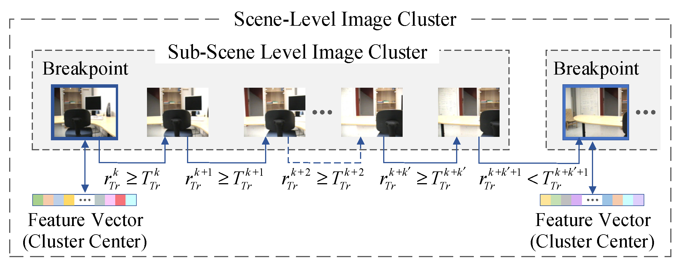
In the proposed HCIR algorithm, the scene-level clustering results are sorted based on the global feature similarity, and then the database images in the sub-scene clusters are sorted based on the local feature similarity. After the two-stage sorting, the query image is matched with database images according to the sorting result. From the above process, it is known that when retrieving the scene-level clustering results based on the global feature similarity, the best case is to obtain the matched image in the first clustering result, and the worst situation is obtaining the matched images after all the results are retrieved. Therefore, for the scene-level image retrieval, the success rate of image retrieval within the top-K clusters is proposed in this paper to evaluate the performance of the clustering algorithm in image retrieval. Specifically, after scene-level clustering of database images, more than one image cluster can be obtained. If the matched database image can be retrieved after searching K image clusters, image retrieval is considered to be achieved within K database image clusters. For a total of n Q query images, if there are n K query images, and their matched database images are in the K-th cluster, the success rate of the top-K clusters is defined as 100 · n K / n Q % . The success rate effectively reflects the impact of the scene-level clustering algorithm on the performance of image retrieval. The scene-level clustering algorithms of database images can be divided into two categories: one is based on the method of detecting change points of visual features (such as the proposed HCIR algorithm in this paper, the mean shift-based algorithm, and the Bayesian estimation-based algorithm), and another is clustering a fixed number of database images (such as the C-GIST algorithm [37]). In the C-GIST algorithm, five consecutive database images are grouped into one cluster, and the cluster center is a feature vector of the image that is located at the center position of each cluster. In this paper, two categories of image-clustering algorithms are simulated, respectively, and the success rate of the top-K clusters is calculated. The results are presented in Table 4.
The results shown in Table 4 indicate that the proposed HCIR algorithm is beneficial in improving the success rate of the top-K clusters for a query image. For the two databases, the success rates of the top-five clusters achieved by the HCIR algorithm, mean shift-based algorithm, and the Bayesian estimation-based algorithm are more than 90%. At the same time, it is not difficult to find that the HCIR algorithm has more obvious performance advantages. Especially in the KTH database, the success rate of the first cluster is 66.75%, and the success rate of the top-five clusters reaches 99.75%. For the HIT-TUM database and the KTH database, the best-matched database image can be retrieved within the top-five clusters by the HCIR algorithm. In addition, for the sub-scene-level image clustering, success rates of the first K-clusters are also calculated and recorded. Experimental results show that for the HCIR algorithm, the success rate of the first cluster is more than 88%, which indicates that in most cases, the best-matched database image can be found in the first sub-cluster.
To verify the image retrieval efficiency of the proposed HCIR algorithm, image retrieval experiments are performed on the HCIR algorithm and the comparison algorithms. In the experiments, the mean shift-based algorithm, the Bayesian estimation-based algorithm, and the C-GIST algorithm are single-layer clustering algorithms. In addition, another two multi-layer clustering algorithms are considered: the mean shift-KLT algorithm and the Bayesian estimation-KLT algorithm. For the two multi-layer clustering algorithms, database images are firstly grouped by the mean shift-based algorithm or the Bayesian estimation-based algorithm, and then the images are further grouped by the KLT algorithm. According to the average number of retrieved images shown in Table 5, multi-layer clustering algorithms have higher retrieval efficiency, and the number of similar comparisons (i.e., the processes of feature matching) can be limited to 10% of the database size. The reason is that database images are only grouped into scene-level clusters for the single-layer algorithms, and thus the query image needs to match with database images in the scene-level cluster one-by-one. In contrast, database images are further grouped on the basis of scene-level image clusters in multi-layer algorithms. Then, according to visual similarities, image clusters are ranked, and the query image preferentially matches with the database images in the most similar cluster. Therefore, multi-layer algorithms have a better performance at average numbers of retrieved database images.
It can be observed from the experimental results shown in Table 5 that fewer database images are retrieved in the HCIR algorithm compared with the other two multi-layer algorithms. The reason is that the ICSCD algorithm has a better performance at scene-level clustering (as shown in Table 2), so that the cluster center can better express the global features of the images in the cluster.
Table 6 shows the average running time of the image-retrieval system using different clustering algorithms. By comparing the number of retrieved images with the average running time of image retrieval, it can be known that when there are more retrieved database images, the running time consumed by image retrieval is also more. Experimental results shown in Table 5 and Table 6 indicate that more database images are retrieved in single-layer clustering algorithms, leading to larger time overheads than in multi-layer clustering algorithms. It is obvious that the HCIR algorithm has advantages in terms of the number of retrieved database images and the running time of image retrieval. The reason is that multi-layer clustering on database images is employed in the HCIR algorithm, and more importantly, the ICSCD algorithm is employed in the proposed retrieval algorithm that achieves a better performance in scene-level database image clustering.
Table 7 shows the average running time of different stages in image retrieval. In the practical implementation of image retrieval, hundreds of local features are needed to be matched between the query image and the database image, resulting in the most time consumption appearing at this stage.
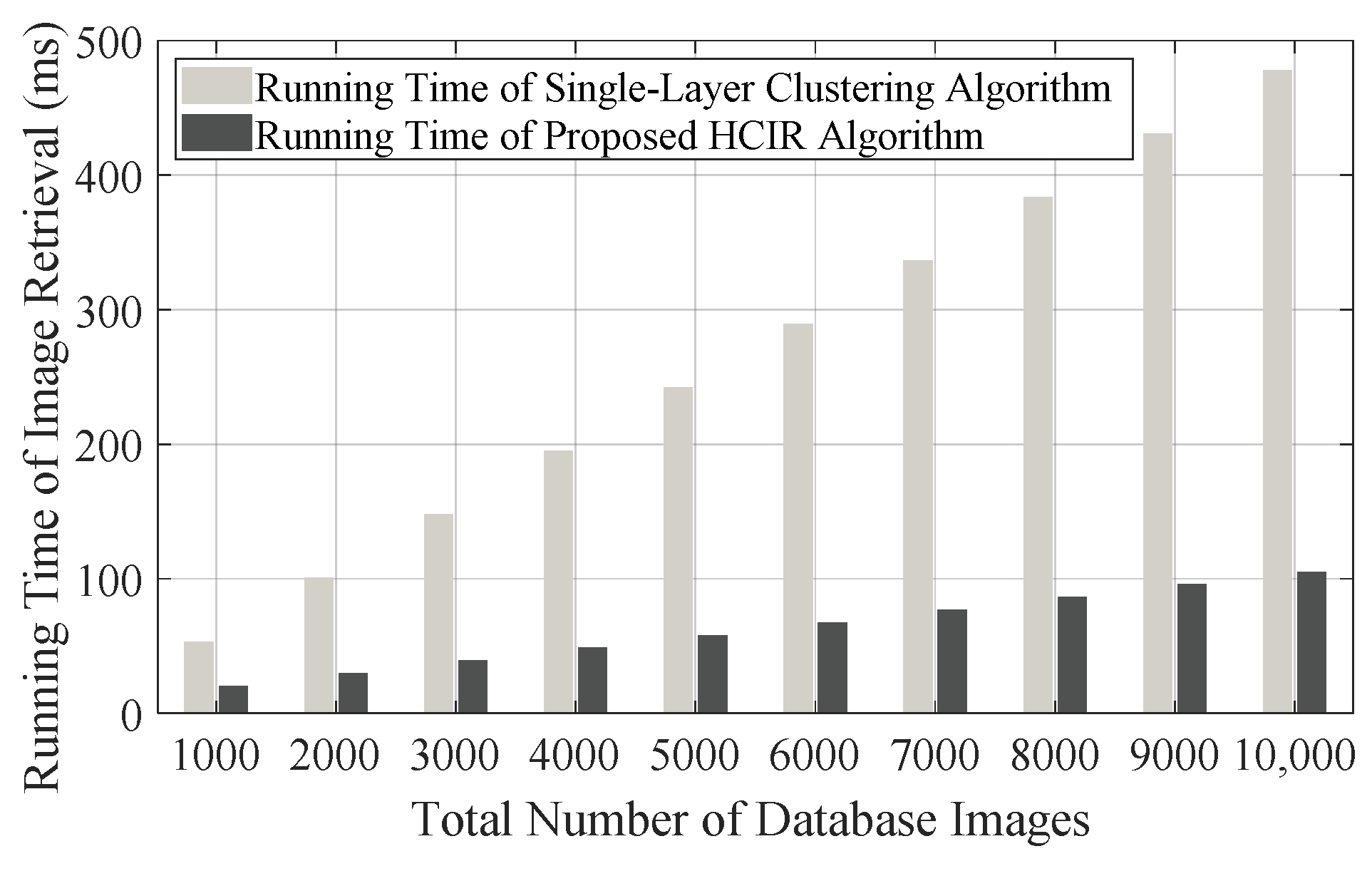
To reveal the performance difference between the single-layer clustering algorithm and the proposed HCIR algorithm, there are ten indoor scenes used for simulation, and m L 1 is separately set as 100, 200, 400, 800, and 1000, and then the running time of image retrieval for different database sizes can be simulated, as shown in Figure 11. As a pre-condition of simulation, the backtracking mechanism is always not triggered. According to the simulation results, the advantage of the proposed algorithm is that the running time does not linearly increase along with the growth of the database size. Even when the database image size is increased to 10,000, the running time of image retrieval is less than 110 ms. In this case, the running time of image retrieval corresponding to the single-layer clustering-based algorithm almost reaches 500 ms, which means that only two retrievals can be performed per second. In contrast, by the proposed HCIR algorithm, image retrieval can be executed nine times when there are 10,000 images in the database. The reason that the proposed algorithm spends less time coping with image retrieval is that database images are reasonably grouped in the off-line stage. Furthermore, on a deeper level, time for image clustering is sacrificed in the off-line stage to reduce the time consumption of image retrieval in the on-line stage.
To demonstrate the performance of the proposed WKNN algorithm, two typical image retrieval-based localization methods (i.e., the NN method [49,54,55] and the KNN method [56,57]) are selected and implemented. Each image in the KTH database and the HIT-TUM database is employed as a query image for visual localization. For the proposed WKNN method and the typical KNN method, five nearest neighbors are selected to estimate the query position [57]. In order to reveal the impact of image acquisition intervals (
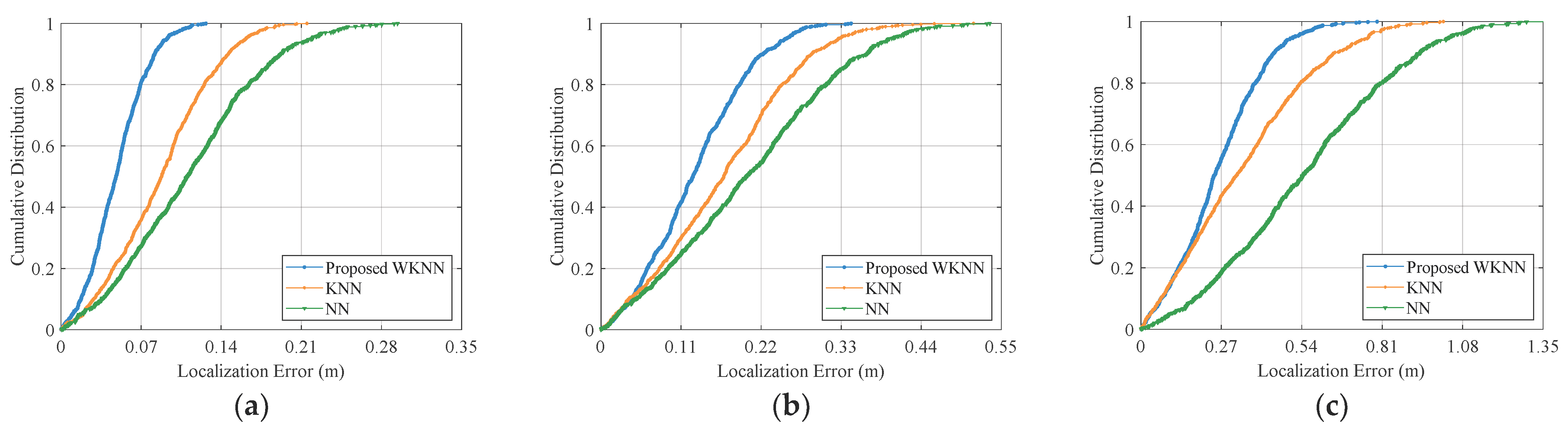
din) on localization accuracy, database images with different acquisition intervals are set for experiments. Localization errors of query images are calculated, and the cumulative distributions of the errors are shown in Figure 12.
To quantitatively analyze the performance improvement of the WKNN method, an accuracy improvement rate rim is introduced and defined as:
r i m = e p e c / e c · 100 %
where e p and e c are the average errors by the proposed WKNN method and the comparative method, respectively.
Compared with the NN and KNN methods, the proposed WKNN method achieves a better performance on localization accuracy, as shown in Table 8. In all experimental cases, the improvement of average localization accuracy reaches at least 22% and 34%, respectively, compared with the KNN and NN methods. From the localization results, it can be found that when the database images are more densely captured, the advantage of the proposed method in terms of localization accuracy is more obvious compared with the two other localization methods. The reason is that when the intervals of database images are large, the common visual features between the query image and the database images are few, which weakens the contributions of the weights in the WKNN method.
As illustrated in Table 8, when the database image acquisition intervals are set to be 10 cm, 20 cm, 30 cm, 40 cm, and 50 cm, the average localization errors of the WKNN method are 0.0490 m, 0.1299 m, 0.2604 m, 0.3673 m, and 0.5048 m, respectively. The results indicate that localization accuracy increases along with database image acquisition intervals. Even if the acquisition interval is increased to 50 cm, the sub-meter localization accuracy can be achieved by the proposed method, which satisfies the requirements of most indoor location-based services. But it is worth noting that acquisition intervals that are too small lead to a large off-line image database and result further in a high time overhead of image retrieval. Therefore, when designing a visual indoor localization system, a proper database image acquisition interval should be selected by striking a balance between localization accuracy and efficiency.

6. Discussion

In the visual localization system, an off-line database generally contains a large number of images for position estimation. For example, over 40,000 database images were captured over a distance of 4.5 km in the TUMindoor localization system, which means that database images were acquired at approximately 10 cm intervals [26]. With the traditional image retrieval strategy, the query image is exhaustively compared with each database image, which is not scalable for a large-scale database. Recently, clustering-based hierarchical image retrieval has been proposed and applied in large-scale image retrieval [63,64,65]. The main advantage of hierarchical image retrieval is creating an indexing strategy by grouping the images based on the visual cues before retrieval, so that only the relevant clusters are examined in the retrieval process. With this strategy, clustering-based hierarchical image retrieval significantly speeds up the search process at the expense of the time consumption of image clustering beforehand.
However, although the existing works on hierarchical image retrieval achieve high searching efficiency, these works are unsuitable for visual localization. The reason is that geographic factors on image clustering have not been taken into consideration, and database images acquired in the same scene are not necessarily grouped in a cluster. In the visual localization system, the query image is desired to be orderly compared with database images in the relevant scenes according to visual similarity. Specifically, the query image should be compared with similar database images as a priority. In this way, the query image need not be compared with all database images, and the retrieval can be obtained.
Considering the particular requirements of image retrieval in visual localization, a hierarchical clustering-based image retrieval (i.e., HCIR) algorithm is proposed in this paper to organize database images and achieve image retrieval. The main contribution to the HCIR method is that database images are orderly grouped into clusters by visual cues according with geographical distribution characteristics. Since the database images for visual localization are successively captured by the mapping equipment in indoor scenes, visual features in the same scene have high visual correlations. However, once the mapping equipment switches to another scene, the correlations subsequently decrease. Taking advantage of this characteristic of database images, an ICSCD algorithm is presented to group database images into clusters at the scene level. Moreover, an image clustering algorithm based on KLT feature tracking is proposed to group database images at the sub-scene level. With the ICSCD algorithm and KLT feature tracking-based algorithms, the visual features of different scenes and sub-scenes can be described by the cluster centers. In the process of retrieval, the query image is initially compared with the cluster centers, and then the clusters that have the largest similarity with the query are selected, and the images in these clusters are used to compare the query. By this means, the database images with high similarities to the query are preferentially retrieved, thus reducing the time consumption of image retrieval.
Compared with the existing change-point detection algorithms (i.e., the mean shift-based algorithm [36] and the Bayesian estimation-based algorithm [62]), the proposed ICSCD algorithm achieves a better performance in terms of scene-level clustering on different evaluation criteria, such as the average recall rate, the average precision rate, the average F1 score, and the accuracy rate. The reason is that the typical CUSUM algorithm is improved at targeting change-point detection on database image sequences without threshold selection. In addition, the utilization of appropriate global visual features and the definition of the change-point detection function also contribute to raising cluster accuracy. On the basis of scene-level clustering results, the KLT feature tracking-based clustering algorithm is employed to further group database images, and then a multi-layer search tree can be generated for image retrieval. A distinguishing characteristic of the search tree is that database image clusters attached to the tree are determined by geo-information and visual cues. The query image is initially compared with cluster centers of the scenes with high similarity, which boosts the retrieval efficiency. The experimental results indicate that the image retrieval by our multi-layer search tree is more efficient compared with other single-layer and multi-layer clustering algorithms, such as the mean shift-based [36], C-Gist [37], Bayesian estimation-based [62], Bayesian estimation-KLT, and mean shift-KLT algorithms. Multi-layer clustering algorithms outperform single-layer algorithms because the KLT feature tracking-based algorithm subdivides the scene-level clusters and groups images at the sub-scene level, resulting in reducing the comparison between the query and database images. Due to the higher accuracy of the ICSCD algorithm on scene-level image clustering, the proposed HCIR algorithm outperforms other multi-layer clustering algorithms on retrieval efficiency, as shown in Table 5 and Table 6.
Visual localization without camera-intrinsic parameters is essential in indoor navigation and augmented reality. Existing works mainly focus on the NN method [49,54,55] and the KNN method [56,57] to solve the estimated position of the query. However, the effect of similarity between the query image and database images on localization is not taken into consideration either in the NN method or in the KNN method. Therefore, a weighted KNN method is proposed, and the Armijo–Goldstein algorithm is employed to calculate the position of the query camera. The highlight of the weighted KNN method is that a novel localization error function is defined in consideration of visual similarity. Specifically, the matched database image with a higher similarity to the query is assigned a larger weight in the localization error function, resulting in the estimated position being close to similar database images. As discussed earlier, the drawback of the NN method is that the position of the most similar database image is assigned to the query, but the database image may be far from the query. For the KNN method, each neighbor database image has the same weight, which is not in accordance with the actual localization situation. The weighted KNN method overcomes these drawbacks by similarity comparison, and neighbor database images with higher similarity are given a larger weight. Experimental results show that the weighted KNN method achieves a better performance on localization accuracy compared with the NN and KNN methods. For a typical interval of database image acquisition (i.e., the interval is approximately 10 cm [26]), the average localization errors are limited to 5 cm, and this outperforms the NN and KNN methods. The proposed WKNN localization method has the potential to be embedded in visually impaired navigation systems and shopping guide applications.

7. Conclusions

In this paper, a hierarchical clustering-based image retrieval algorithm is presented, in which database images are grouped by improved cumulative sum change-point detection and KLT feature tracking. Taking advantage of hierarchical clusters, database images that are similar to the query image have a priority to match with the query, which effectively reduces the time consumption of image retrieval. For different indoor image databases, the number of similar comparisons can be limited to 10% of the database size. Simulation experiments also indicate that the running time of image retrieval does not linearly increase with the size of image databases. Compared with other single-layer and multi-layer clustering-based image retrieval algorithms, the proposed HCIR algorithm executes less similar comparisons and acquires low time overheads. Under the premise of ensuring image retrieval accuracy, the proposed visual localization system achieves high operational efficiency. With the proposed localization method, the position estimation error is limited to 5 cm when the database image acquisition intervals are set to 10 cm. Future work will focus on improving the accuracy of visual localization, especially reducing the impact of illumination changes on localization.

Author Contributions

Conceptualization, G.F. and X.T.; methodology, G.F.; software, G.F.; validation, G.F., Z.J. and X.T.; formal analysis, G.F.; investigation, G.F.; resources, G.F.; data curation, G.F.; writing—G.F.; writing—review and editing, G.F. and F.C.; visualization, G.F.; supervision, X.T.; project administration, G.F., X.T. and Z.J.; funding acquisition, G.F. All authors have read and agreed to the published version of the manuscript.

Funding

This research was funded by the Natural Science Foundation of Jilin Province, China [Grant No. 20210101170JC].

Conflicts of Interest

The authors declare no conflict of interest.

References

  1. Zangenehnejad, F.; Gao, Y. GNSS smartphones positioning: Advances, challenges, opportunities, and future perspectives. Sat. Nav. 2021, 2, 24. [Google Scholar] [CrossRef] [PubMed]
  2. Zidan, J.; Adegoke, E.I.; Kampert, E.; Birrell, S.A.; Ford, C.R.; Higgins, M.D. GNSS vulnerabilities and existing solutions: A review of the literature. IEEE Access 2020, 9, 153960–153976. [Google Scholar] [CrossRef]
  3. Zhu, N.; Marais, J.; Bétaille, D.; Berbineau, M. GNSS position integrity in urban environments: A review of literature. IEEE Trans. Intell. Transp. Syst. 2018, 19, 2762–2778. [Google Scholar] [CrossRef] [Green Version]
  4. Guo, L.; Wang, F.; Sang, J.; Lin, X.; Gong, X.; Zhang, W. Characteristics analysis of raw multi-GNSS measurement from Xiaomi Mi 8 and positioning performance improvement with L5/E5 frequency in an urban environment. Remote Sens. 2020, 12, 744. [Google Scholar] [CrossRef] [Green Version]
  5. Feng, X.; Nguyen, K.A.; Luo, Z. A survey of deep learning approaches for WiFi-based indoor positioning. J. Inf. Telecommun. 2022, 6, 163–216. [Google Scholar] [CrossRef]
  6. Mendoza-Silva, G.M.; Costa, A.C.; Torres-Sospedra, J.; Painho, M.; Huerta, J. Environment-aware regression for indoor localization based on WiFi fingerprinting. IEEE Sens. J. 2021, 22, 4978–4988. [Google Scholar] [CrossRef]
  7. Bencak, P.; Hercog, D.; Lerher, T. Indoor Positioning System Based on Bluetooth Low Energy Technology and a Nature-Inspired Optimization Algorithm. Electronics 2022, 11, 308. [Google Scholar] [CrossRef]
  8. Lie, M.M.K.; Kusuma, G.P. A fingerprint-based coarse-to-fine algorithm for indoor positioning system using Bluetooth Low Energy. Neural. Comput. Appl. 2021, 33, 2735–2751. [Google Scholar] [CrossRef]
  9. Guo, H.; Li, M.; Zhang, X.; Gao, X.; Liu, Q. UWB indoor positioning optimization algorithm based on genetic annealing and clustering analysis. Front. Neurorobot. 2022, 16, 715440. [Google Scholar] [CrossRef]
  10. Wang, J.; Wang, M.; Yang, D.; Liu, F.; Wen, Z. UWB positioning algorithm and accuracy evaluation for different indoor scenes. Int. J. Image Data Fusion 2021, 12, 203–225. [Google Scholar] [CrossRef]
  11. Zhang, X.; Kuang, Y.; Yang, H.; Lu, H.; Yang, Y. UWB Indoor Localization Algorithm Using Firefly of Multistage Optimization on Particle Filter. J. Sens. 2021, 2021, 1383767. [Google Scholar] [CrossRef]
  12. Zhang, W.; Hua, X.; Yu, K.; Qiu, W.; Zhang, S.; He, X. A novel WiFi indoor positioning strategy based on weighted squared Euclidean distance and local principal gradient direction. Sens. Rev. 2019, 39, 99–106. [Google Scholar] [CrossRef]
  13. Huang, B.; Yang, R.; Jia, B.; Li, W.; Mao, G. Accurate WiFi localization by fusing a group of fingerprints via a global fusion profile. IEEE Trans. Veh. Technol. 2021, 70, 3599–3608. [Google Scholar] [CrossRef]
  14. Lu, C.; Uchiyama, H.; Thomas, D.; Shimada, A.; Taniguchi, R. Indoor positioning system based on chest-mounted IMU. Sensors 2019, 19, 420. [Google Scholar] [CrossRef] [PubMed] [Green Version]
  15. Zhang, Y.; Guo, J.; Wang, F.; Zhu, R.; Wang, L. An Indoor Localization Method Based on the Combination of Indoor Map Information and Inertial Navigation with Cascade Filter. J. Sens. 2021, 2021, 7621393. [Google Scholar] [CrossRef]
  16. Sun, M.; Wang, Y.; Joseph, W.; Plets, D. Indoor localization using mind evolutionary algorithm-based geomagnetic positioning and smartphone IMU sensors. IEEE Sens. J. 2022, 22, 7130–7141. [Google Scholar] [CrossRef]
  17. Guo, G.; Chen, R.; Ye, F.; Liu, Z.; Xu, S.; Huang, L.; Li, Z.; Qian, L. A robust integration platform of Wi-Fi RTT, RSS signal and MEMS-IMU for locating commercial smartphone indoors. IEEE Internet Things J. 2022, 9, 16322–16331. [Google Scholar] [CrossRef]
  18. Krishnaveni, B.V.; Reddy, K.S.; Reddy, P.R. Indoor tracking by adding IMU and UWB using Unscented Kalman filter. Wirel. Pers. Commun. 2022, 123, 3575–3596. [Google Scholar] [CrossRef]
  19. Feng, G.; Ma, L.; Tan, X.; Qin, D. Drift-aware monocular localization based on a pre-constructed dense 3D map in indoor environments. ISPRS Int. J. Geo-Inf. 2018, 7, 299. [Google Scholar] [CrossRef] [Green Version]
  20. Piciarelli, C. Visual indoor localization in known environments. IEEE Signal Process. Lett. 2016, 23, 1330–1334. [Google Scholar] [CrossRef]
  21. Li, X.; Zhao, L.; Ji, W.; Wu, Y.; Wu, F.; Yang, M.H.; Tao, D.; Reid, I. Multi-task structure-aware context modeling for robust keypoint-based object tracking. IEEE Trans. Pattern Anal. Mach. Intell. 2018, 41, 915–927. [Google Scholar] [CrossRef]
  22. Zhang, H.; Hong, X. Recent progresses on object detection: A brief review. Multimed. Tools Appl. 2019, 78, 27809–27847. [Google Scholar] [CrossRef]
  23. Schmarje, L.; Santarossa, M.; Schröder, S.M.; Koch, R. A survey on semi-, self-and unsupervised learning for image classification. IEEE Access 2019, 9, 82146–82168. [Google Scholar] [CrossRef]
  24. Wang, X.; Zheng, Z.; He, Y.; Yan, F.; Zeng, Z.; Yang, Y. Progressive local filter pruning for image retrieval acceleration. arXiv 2020, arXiv:2001.08878. [Google Scholar]
  25. Sadeghi, H. Image-Based Localization for Mobile and Vehicular Applications. Ph.D. Thesis, University of Toronto, Toronto, ON, Canada, 2017. [Google Scholar]
  26. Huitl, R.; Schroth, G.; Hilsenbeck, S.; Schweiger, F.; Steinbach, E. TUMindoor: An extensive image and point cloud dataset for visual indoor localization and mapping. In Proceedings of the 19th IEEE International Conference on Image Processing, Orlando, FL, USA, 30 September–3 October 2012. [Google Scholar]
  27. Ge, R. Real-Time Visual Localization System in Changing and Challenging Environments via Visual Place Recognition. Ph.D. Thesis, Carnegie Mellon University, Pittsburgh, PA, USA, 2022. [Google Scholar]
  28. Humenberger, M.; Cabon, Y.; Pion, N.; Weinzaepfel, P.; Lee, D.; Guérin, N.; Sattler, T.; Csurka, G. Investigating the role of image retrieval for visual localization. Int. J. Comput. Vis. 2022, 130, 1811–1836. [Google Scholar] [CrossRef]
  29. Yu, L.; Fu, X.; Xu, H.; Fei, S. High-precision camera pose estimation and optimization in a large-scene 3D reconstruction system. Meas. Sci. Technol. 2020, 31, 085401. [Google Scholar] [CrossRef]
  30. Feng, G.; Ma, L.; Tan, X. Visual map construction using RGB-D sensors for image-based localization in indoor environments. J. Sens. 2017, 2017, 8037607. [Google Scholar] [CrossRef] [Green Version]
  31. Deretey, E.; Ahmed, M.T.; Marshall, J.A.; Greenspan, M. Visual indoor positioning with a single camera using PnP. In Proceedings of the IEEE International Conference on Indoor Positioning and Indoor Navigation, Banff, AB, Canada, 13–16 October 2015. [Google Scholar]
  32. Wang, J.; Zha, H.; Cipolla, R. Coarse-to-fine vision-based localization by indexing scale-invariant features. IEEE Trans. Syst. Man Cybern. Part B (Cybern.) 2006, 36, 413–422. [Google Scholar] [CrossRef]
  33. Anandh, A.; Mala, K.; Suganya, S. Content based image retrieval system based on semantic information using color, texture and shape features. In Proceedings of the IEEE International Conference on Computing Technologies and Intelligent Data Engineering, Kovilpatti, India, 7–9 January 2016. [Google Scholar]
  34. Singh, S.R.; Kohli, S. Enhanced CBIR using color moments HSV histogram color auto correlogram and Gabor texture. Int. J. Comput. Syst. 2015, 2, 161–165. [Google Scholar]
  35. Oliva, A.; Torralba, A. Building the gist of a scene: The role of global image features in recognition. Prog. Brain Res. 2006, 155, 23–36. [Google Scholar]
  36. Chapoulie, A.; Rives, P.; Filliat, D. Topological segmentation of indoors/outdoors sequences of spherical views. In Proceedings of the IEEE/RSJ International Conference on Intelligent Robots and Systems, Vilamoura-Algarve, Portugal, 7–12 October 2012. [Google Scholar]
  37. Ma, L.; Xue, H.; Jia, T.; Tan, X. A fast C-GIST based image retrieval method for vision-based indoor localization. In Proceedings of the IEEE Vehicular Technology Conference, Sydney, NSW, Australia, 4–7 June 2017. [Google Scholar]
  38. Bay, H.; Tuytelaars, T.; Van, G.L. SURF: Speeded Up Robust Features. In Proceedings of the European Conference on Computer Vision, Graz, Austria, 7–13 May 2006. [Google Scholar]
  39. Lowe, D.G. Object recognition from local scale-invariant features. In Proceedings of the 7th IEEE International Conference on Computer Vision, Kerkyra, Greece, 20–27 September 1999. [Google Scholar]
  40. Rublee, E.; Rabaud, V.; Konolige, K.; Bradski, G. ORB: An efficient alternative to SIFT or SURF. In Proceedings of the IEEE International Conference on Computer Vision, Barcelona, Spain, 6–13 November 2012. [Google Scholar]
  41. Ni, J.; Wang, X.; Gong, T.; Xie, Y. An improved adaptive ORB-SLAM method for monocular vision robot under dynamic environments. Int. J. Mach. Learn. Cybern. 2022, 13, 3821–3836. [Google Scholar] [CrossRef]
  42. Chhabra, P.; Garg, N.K.; Kumar, M. Content-based image retrieval system using ORB and SIFT features. Neural. Comput. Appl. 2020, 32, 2725–2733. [Google Scholar] [CrossRef]
  43. Bel, K.N.S.; Sam, I.S. Encrypted image retrieval method using SIFT and ORB in cloud. In Proceedings of the 7th IEEE International Conference on Smart Structures and Systems, Chennai, India, 23–24 July 2020. [Google Scholar]
  44. Sadeghi, H.; Valaee, S.; Shirani, S. 2DTriPnP: A robust two-dimensional method for fine visual localization using Google streetview database. IEEE Trans. Veh. Technol. 2017, 66, 4678–4690. [Google Scholar] [CrossRef]
  45. Naseer, T.; Burgard, W.; Stachniss, C. Robust visual localization across seasons. IEEE Trans. Robot. 2018, 34, 289–302. [Google Scholar] [CrossRef]
  46. Boin, J.B.; Bobkov, D.; Steinbach, E.; Girod, B. Efficient panorama database indexing for indoor localization. In Proceedings of the 2019 IEEE International Conference on Content-Based Multimedia Indexing, Dublin, Ireland, 4–6 September 2019. [Google Scholar]
  47. Lanir, J.; Kuflik, T.; Wecker, A.J.; Stock, O.; Zancanaro, M. Examining proactiveness and choice in a location-aware mobile museum guide. Interact. Comput. 2011, 23, 513–524. [Google Scholar] [CrossRef]
  48. Tseng, P.Y.; Lin, J.J.; Chan, Y.C.; Chen, A.Y. Real-time indoor localization with visual SLAM for in-building emergency response. Interact. Comput. 2022, 140, 104319. [Google Scholar] [CrossRef]
  49. Zhang, W.; Kosecka, J. Image based localization in urban environments. In Proceedings of the 3rd IEEE International Symposium on 3D Data Processing, Visualization, and Transmission, Chapel Hill, NC, USA, 14–16 June 2006. [Google Scholar]
  50. Vedadi, F.; Valaee, S. Automatic visual fingerprinting for indoor image-based localization applications. IEEE Trans. Syst. Man Cybern. Syst. 2017, 50, 305–317. [Google Scholar] [CrossRef]
  51. Taira, H.; Okutomi, M.; Sattler, T.; Cimpoi, M.; Pollefeys, M.; Sivic, J.; Pajdla, T.; Torii, A. InLoc: Indoor visual localization with dense matching and view synthesis. IEEE Trans. Pattern Anal. 2019, 43, 1293–1307. [Google Scholar] [CrossRef] [Green Version]
  52. Zhang, Z.; Sattler, T.; Scaramuzza, D. Reference pose generation for long-term visual localization via learned features and view synthesis. Int. J. Comput. Vis. 2021, 129, 821–844. [Google Scholar] [CrossRef]
  53. Li, N.; Ai, H. EfiLoc: Large-scale visual indoor localization with efficient correlation between sparse features and 3D points. Vis. Comput. 2022, 38, 2091–2106. [Google Scholar] [CrossRef]
  54. Van, O.D.; Schroth, G.; Huitl, R.; Hilsenbeck, S.; Garcea, A.; Steinbach, E. Camera-based indoor positioning using scalable streaming of compressed binary image signatures. In Proceedings of the IEEE International Conference on Image Processing, Paris, France, 27–30 October 2014. [Google Scholar]
  55. Spera, E.; Furnari, A.; Battiato, S.; Farinella, G.M. Performance comparison of methods based on image retrieval and direct regression for egocentric shopping cart localization. In Proceedings of the IEEE 4th International Forum on Research and Technology for Society and Industry, Palermo, Italy, 10–13 September 2018. [Google Scholar]
  56. Spera, E.; Furnari, A.; Battiato, S.; Farinella, G.M. EgoCart: A benchmark dataset for large-scale indoor image-based localization in retail stores. IEEE Trans. Circuits Syst. Video Technol. 2019, 31, 1253–1267. [Google Scholar] [CrossRef]
  57. He, R.; Wang, Y.; Tao, Q.; Cai, J.; Duan, L. Efficient image retrieval based mobile indoor localization. In Proceedings of the IEEE Visual Communications and Image Processing, Singapore, 13–16 December 2015. [Google Scholar]
  58. Peng, X.; Chen, R.; Yu, K.; Guo, G.; Ye, F.; Xue, W. A new Wi-Fi dynamic selection of nearest neighbor localization algorithm based on RSS characteristic value extraction by hybrid filtering. Meas. Sci. Technol. 2021, 32, 034003. [Google Scholar] [CrossRef]
  59. Bishop, C.M. Pattern Recognition and Machine Learning (Information Science and Statistics); Springer: New York, NY, USA, 2006; pp. 650–656. [Google Scholar]
  60. Sun, W.Y.; Yuan, Y.X. Optimization Theory and Methods: Nonlinear Programming; Springer: New York, NY, USA, 2005; pp. 103–104. [Google Scholar]
  61. Luo, J.; Pronobis, A.; Caputo, B.; Jensfelt, P. Incremental learning for place recognition in dynamic environments. In Proceedings of the IEEE/RSJ International Conference on Intelligent Robots and Systems, San Diego, CA, USA, 29 October–2 November 2007. [Google Scholar]
  62. Ranganathan, A. PLISS: Labeling places using online changepoint detection. Auton. Robot. 2012, 32, 351–368. [Google Scholar] [CrossRef]
  63. Yan, C.; Bai, X.; Zhou, J.; Liu, Y. Hierarchical hashing for image retrieval. In Proceedings of the CCF Chinese Conference on Computer Vision, Tianjin, China, 11–14 October 2017. [Google Scholar]
  64. Munoz, J.V.; Gonçalves, M.A.; Dias, Z.; Torres, R.D.S. Hierarchical clustering-based graphs for large scale approximate nearest neighbor search. Pattern Recognit. 2019, 96, 106970. [Google Scholar] [CrossRef]
  65. Xie, H.; Chen, W.; Wang, J. Hierarchical forest based fast online loop closure for low-latency consistent visual-inertial SLAM. Robot. Auton. Syst. 2022, 151, 104035. [Google Scholar] [CrossRef]
Figure 1. System model of indoor visual localization.
Electronics 11 03609 g001
Figure 2. Examples of database images and the corresponding spectrograms of Gist features.
Electronics 11 03609 g002
Figure 3. Diagram of sliding windows in CUSUM change-point detection.
Electronics 11 03609 g003
Figure 4. Diagram of change-point detection for database images.
Electronics 11 03609 g004
Figure 5. Illustration of sub-scene-level clustering based on feature tracking.
Electronics 11 03609 g005
Figure 6. Schematic diagram of search tree in image hierarchical retrieval.
Electronics 11 03609 g006
Figure 7. Diagram of maximum similarity method for finding the best-matched database image.
Electronics 11 03609 g007
Figure 8. Randomly selected example images of the KTH and HIT-TUM databases.
Electronics 11 03609 g008
Figure 9. Examples of pre-processing results of Gist features of database images. (a) Pre-processing results of Gist features for KTH database images with S G = 1 and O G = 0 ° ; (b) Pre-processing results of Gist features for KTH database images with S G = 2 and O G = 6 0 ° ; (c) Pre-processing results of Gist features for KTH database images with S G = 3 and O G = 12 0 ° ; (d) Pre-processing results of Gist features for HIT-TUM database images with S G = 1 and O G = 0 ° ; (e) Pre-processing results of Gist features for HIT-TUM database images with S G = 2 and O G = 6 0 ° ; (f) Pre-processing results of Gist features for HIT-TUM database images with S G = 3 and O G = 12 0 ° .
Electronics 11 03609 g009aElectronics 11 03609 g009b
Figure 10. Confusion matrices of database image clustering. (a) Confusion matrix of KTH database image clustering; (b) confusion matrix of HIT-TUM database image clustering.
Electronics 11 03609 g010
Figure 11. Average running time of the single-layer clustering algorithm and proposed algorithm.
Electronics 11 03609 g011
Figure 12. Experimental results of visual localization. (a) Cumulative distribution of localization errors with din = 10 cm; (b) cumulative distribution of localization errors with din = 20 cm; (c) cumulative distribution of localization errors with din = 30 cm; (d) cumulative distribution of localization errors with din = 40 cm; (e) cumulative distribution of localization errors with din = 50 cm.
Electronics 11 03609 g012aElectronics 11 03609 g012b
Table 1. Performance comparison of scene-level clustering of global features.
DatabaseType of Global Feature Average   Recall   Rate   r ¯ R R Average   Precision   Rate   r ¯ P R Average   F 1   Score   s ¯ F 1 Accuracy Rate
r ¯ A R
KTHColor histogram0.56020.55590.55460.5575
Color moment0.57320.56970.56830.5650
Wavelet transform0.69460.68980.69040.6875
Gabor transform0.81780.80710.81020.8400
Gist0.93200.93880.93220.9325
HIT-TUMColor histogram0.53840.53700.53430.5475
Color moment0.56070.55990.55780.5725
Wavelet transform0.66010.66110.65920.6775
Gabor transform0.82590.82060.82210.8325
Gist0.93240.94890.93750.9225
Table 2. Performance comparison of scene-level image clustering algorithms.
DatabaseAlgorithm Average   Recall   Rate   r ¯ R R Average   Precision   Rate   r ¯ P R Average   F 1   Score   s ¯ F 1 Accuracy Rate
r ¯ A R
KTHProposed ICSCD algorithm0.93200.93880.93220.9325
Mean shift-based algorithm0.86450.91070.84910.8625
Bayesian estimation-based algorithm0.78170.84080.77590.7925
HIT-TUMProposed ICSCD algorithm0.93240.94890.93750.9225
Mean shift-based algorithm0.84040.84850.83330.8475
Bayesian estimation-based algorithm0.74970.76920.73870.7550
Table 3. Experimental results of matched database image retrieval.
Database r S 0 r S 1 r S 2 ε i n d e x ε d i s   s ¯ L n ¯ m a t
KTH94.75%4.50%0.75%0.060.60 cm0.5453121.45
HIT-TUM96.50%3.00%0.50%0.040.40 cm0.6287134.40
Table 4. Success rates of the top-K clusters for query image.
DatabaseAlgorithmK = 1K = 2K = 3K = 4K = 5
KTHProposed HCIR algorithm66.75%87.50%93.50%99.75%100%
Mean shift-based50.25%72.75%84.25%91.50%97.75%
Bayesian estimation-based45.75%64.75%74.25%82.75%91.00%
C-GIST29.25%35.25%39.50%43.25%47.25%
HIT-TUMProposed HCIR algorithm60.50%82.50%97.00%99.00%100%
Mean shift-based49.25%63.25%83.25%90.25%96.25%
Bayesian estimation-based43.00%59.75%76.50%87.00%93.25%
C-GIST29.75%38.25%49.75%56.50%61.75%
Table 5. Average numbers of retrieved database images by different clustering algorithms.
DatabaseC-GIST Bayesian Estimation Mean ShiftBayesian Estimation-KLT Mean Shift-KLT Proposed HCIR Algorithm
KTH122.1489.1187.1779.6053.6938.81
HIT-TUM163.0178.2175.3248.7046.2224.47
Table 6. Average running time of image retrieval by different clustering algorithms (unit: ms).
DatabaseC-GIST Bayesian Estimation Mean
Shift
Bayesian Estimation-KLT Mean Shift-KLT Proposed HCIR Algorithm
KTH131.762296.180494.670691.985868.168950.5838
HIT-TUM177.634592.880489.917957.406556.027437.4582
Table 7. Average running time of different stages in image retrieval (unit: ms).
Extracting Global FeaturesExtracting Local FeaturesMeasuring Feature DistanceMatching Local FeatureSorting Feature Vectors
0.76483.22470.11310.94370.0169
Table 8. Localization performance of various localization methods.
Image Acquisition IntervalsEvaluation CriterionsWKNN MethodKNN MethodNN Method
din = 10 cmAverage Errors (m)0.04900.08740.1126
Maximum Errors (m)0.12660.21490.2942
Improvement Rates (%)-43.902256.4623
din = 20 cmAverage Errors (m)0.12990.16890.2042
Maximum Errors (m)0.34390.51180.5342
Improvement Rates (%)-23.1101436.4159
din = 30 cmAverage Errors (m)0.26040.34460.5543
Maximum Errors (m)0.79281.01511.3583
Improvement Rates (%)-24.426153.0155
din = 40 cmAverage Errors (m)0.36730.48830.6289
Maximum Errors (m)1.02181.29651.6804
Improvement Rates (%)-24.767841.5920
din = 50 cmAverage Errors (m)0.50480.65040.7732
Maximum Errors (m)1.04621.65182.2218
Improvement Rates (%)-22.388634.7127
Publisher’s Note: MDPI stays neutral with regard to jurisdictional claims in published maps and institutional affiliations.

