Article

Performance Evaluation of an On-Body Wireless Body Network Based on an Ultra-Wideband Physical Layer under a Dynamic Channel Model

by
Kento Takabayashi
1,*,
Hirokazu Tanaka
2 and
Katsumi Sakakibara
1
1
Department of Information and Communication Engineering, Faculty of Computer Science and Systems Engineering, Okayama Prefectural University, Okayama 719-1197, Japan
2
Graduate School of Information Sciences, Hiroshima City University, 3-4-1, Ozuka-Higashi, Asa-Minami-Ku, Hiroshima 731-3194, Japan
*
Author to whom correspondence should be addressed.
Electronics 2022, 11(21), 3491; https://doi.org/10.3390/electronics11213491
Submission received: 21 September 2022 / Revised: 24 October 2022 / Accepted: 26 October 2022 / Published: 27 October 2022
(This article belongs to the Special Issue Advances in Wireless Networks and Mobile Systems)

Abstract

:
Wireless body area networks (WBANs) are attracting attention as an important technology for realizing the Internet of Medical Things (IoMT). In addition, ultra-wideband (UWB) is one of the wireless communication technologies suitable for the IoMT and WBANs. Our previous study investigated the feasibility of WBANs utilizing UWB under ideal and static wearable WBAN channel models. The present research applies a dynamic on-body UWB channel model to a WBAN as a more realistic channel model. The feasibility of a high-reliability UWB-WBAN is demonstrated by evaluating the physical layer performance. Numerical results reveal the maximum number of retransmissions needed to achieve the desired transmission failure ratio for each link type and the corresponding energy efficiency and average number of retransmissions. These findings contribute to the realization of a highly reliable IoMT utilizing UWB-WBANs in a practical environment.

Graphical Abstract

1. Introduction

The Internet of Medical Things (IoMT) presents new physical and temporal challenges for the application of the Internet of Things (IoT) paradigm in the medical field for devices that do not have an established network, such as smart appliances and smart cities [1,2,3,4,5]. It can mitigate communication restrictions and realize medical care and healthcare that meet the needs of users. Key fundamental technologies for the IoMT include wireless sensors, smartphones, communication modules, edge computing, extended reality (XR), blockchain, and artificial intelligence (AI). Based on these IoMT technologies, applications in healthcare, early diagnosis, and remote monitoring are emerging. From a technical point of view, these systems need to exchange data quickly in real time, and in the future, safer mechanisms and high-speed, highly reliable wireless communication technologies will be needed. The global epidemic of COVID-19 is transforming people’s lifestyles and promoting the further development of IoMT technologies. For example, systems that support exercise and dietary improvement using a wearable device, remote medical care, drug delivery to home caregivers, and patient information sharing in local governments are being developed. In the future, it is expected that communication between people and machines and between machines and machines will become more active in terms of both hardware and software. It is also expected that an increasing number of new technologies that can detect health problems and improve treatment in the early stage will continue to be realized.
One of the key technologies for configuring the IoMT is wireless body area network (WBAN) technology [6,7,8,9,10,11,12,13,14,15]. ‘WBAN’ is a general term for a short-range wireless network that is constructed with sensors and devices placed on or near the surface of the human body or inside the body and includes human communication. In February 2012, the wireless communication method for WBANs was internationally standardized as IEEE 802.15.6 [16]. In April 2015, the European Telecommunications Standards Institute (ETSI) formulated the technical specifications for a Smart Body Area Network (SmartBAN) [17,18]. These international standards are still being revised. WBANs can be roughly divided into “implanted” or “in-body” WBANs, which target the inside of the body, and “wearable” or “on-body” WBANs, which target the surface and vicinity of the body. The use of implanted WBANs, which rely on implantable devices, has not been very widespread to date because they are specialized for the medical field. On the other hand, the sensors and wireless modules used in wearable WBANs remain a focus of active research due to technical issues such as size. Nevertheless, with the progress achieved in IoT research in recent years, the size problem of these sensors and modules is being solved, and efforts to utilize WBANs for medical care and healthcare are accelerating against the background of an aging population and increasing awareness of health.
Ultra-wideband (UWB) is a wireless communication technology suitable for the IoMT and WBANs [16,19,20,21,22]. In particular, impulse radio (IR)-UWB based on short duration pulses on the order of a few nanoseconds has received much attention in both academia and industry. In recent years, IR-UWB wireless positioning and ranging functionalities have been applied for keyless entry in automobiles and in mobile devices such as the iPhone 11 and Android 12, and the commercialization of services that are difficult to realize with other wireless communication technologies has begun to spread. Taking advantage of its ultrawide frequency band and very short pulse, IR-UWB has the following features not found in other wireless communication methods: (1) ultrahigh speed and large capacity, (2) ultrahigh-precision positioning and distance measurement, (3) simultaneous realization of communication and positioning or distance measurement, and (4) coexistence with other wireless systems through frequency sharing. As an example of an IoMT application utilizing IR-UWB, behavior monitoring of patients with ataxia is being investigated [23]. Ataxia is a condition in which various movements related to the desired movement become uncoordinated and cannot be smoothly performed. For diagnosis, the patient needs to confirm the intended movement, and the walking movement is especially important. To address this challenge, IR-UWB technology can help detect human walking activity and track human movements.
Notably, the channel model of a WBAN changes dynamically in accordance with the positions of the sensor and hub and the movement of the person [24,25,26]. It is known from the literature that the received electric field strength follows an inverse Gaussian distribution, especially in the UWB physical layer [25,26]. However, the performance of a WBAN in which this channel model is applied has not yet been evaluated. In particular, under the assumption of the above application, the communication performance changes depending on the positional relationship between the sensor and the hub; consequently, data transmission/reception and tracking may fail, and appropriate diagnosis may not be possible.
To address this problem, this channel model is applied to a WBAN under the assumption of a UWB physical layer in the present study, and the feasibility of such a UWB-WBAN is demonstrated by evaluating the transmission failure ratio, energy efficiency, and number of packet retransmissions. The first contribution of this paper is to clarify the performance for each dynamic category in the UWB-WBAN dynamic channel. The second contribution is to show that an error-correcting code suitable for UWB-WBAN is also effective in the dynamic channel model, and to clarify the optimal combination of the error-correcting code and UWB physical layer parameters. Finally, these contributions are considered to contribute to the realization of a highly reliable IoMT utilizing UWB-WBANs.
The remainder of this paper is organized as follows. Section 2 presents previous work related to this research. In Section 3, the UWB physical layer specifications of IEEE 802.15.6 and the system model are summarized. The numerical results of the performance evaluation are reported in Section 4. Section 5 discusses the results obtained in the performance evaluation and their possible implications. Conclusions and suggestions for future research are presented in Section 6.

2. Related Work

Beyond [24,25,26], other related studies on WBAN dynamic channel models include the following. A general empirical system loss model for estimating propagation loss in WBANs for off-body communications at 2.45 GHz was presented, which was implemented in dynamic cases [27]. A channel model for time-variant multilink WBANs based on an extensive measurement campaign using a multiport channel sounder was proposed [28]. The authors of [29] provided a comprehensive mathematical channel model of the surface-to-surface UWB radio links categorized as channel model (CM) 3 in [30] around a moving human torso, whose bandwidth was 3.1–10 GHz. An off-body channel model in which the path loss and multipath fading were entirely determined by the Rician distribution and linked through a stochastic Rician factor K was proposed [31]. The path loss fluctuations of some human body links when the human body was walking or running, with a focus on the millimeter wave (mmWave) band, particularly 28 GHz were analyzed [32].
Notably, a UWB physical layer (PHY) has a very low power spectral density limit, which is defined as G l i m = −41.3 dBm/MHz depending on regulations [16,33]. Therefore, the dependability of communications in the UWB PHY is required to be ensured. To improve the dependability of wireless communication, the application of an error control scheme can be considered. Related studies on the performance evaluation of a UWB-WBAN PHY are listed as follows. [34] described an energy efficiency optimization model for a UWB-WBAN based on the IEEE 802.15.6 standard. The proposed model compared the energy efficiency of uncoded and coded transmissions using different Bose–Chaudhuri–Hocquenghem (BCH) coding rates. [35] presented an evaluation of various performance metrics, such as the bit error ratio (BER) and packet error ratio (PER), for various pulse position modulation (PPM) and demodulation employed in PPM-based IR-UWB receivers designed to satisfy the specifications of the IEEE 802.15.6 standard. [36] evaluated the performance of a virtual multi-input and multioutput (VMIMO) design in an infrared (IR)-UWB-based WBAN system. Our own previous research presented a quality-of-service (QoS) control scheme utilizing decomposable codes for an IEEE 802.15.6 based UWB-WBAN [37]. In addition, our previous research reported a performance evaluation in terms of the transmission failure ratio and energy efficiency for the UWB PHY of IEEE 802.15.6 under the application of a super-orthogonal convolutional code (SOCC) [38]. Ref. [38] confirmed the higher dependability obtained by concatenating an SOCC and a Reed–Solomon (RS) code under additive white Gaussian noise (AWGN) and the WBAN channel model referenced in [30].
Other related research includes: a performance-to-cost analysis of Deterministic and Synchronous Multi-channel Extension (DSME) and Time-slotted Channel Hopping (TSCH) medium access control (MAC) modes of IEEE 802.15.4e with 802.15.4 MAC protocol was presented [39]. Two types of interference mitigation strategies for IEEE 802.15.4 based WBAN were proposed, which were called as passive schemes and active schemes [40].
In previous research, the performance evaluation of WBAN physical layer and MAC protocol was performed assuming an ideal channel model and a static wearable channel model. On the other hand, this work newly evaluates the physical layer performance of UWB-WBAN assuming an on-body dynamic channel model, which was not done in the above studies.

3. Materials and Methods

3.1. IEEE 802.15.6 UWB PHY

3.1.1. Operating Frequency Bands and Spectral Mask

The UWB band is classified into two groups: one is a low band (channels 0–2), and another is a high band (channels 3–10) [16,38]. Those bands are also divided into operating channels, each with a bandwidth of 499.2 MHz, as presented in Figure 1. The mandatory channel of the low band is channel 1, whose center frequency f c is 3993.6 MHz. On the other hand, that of the high band is channel 6, whose center frequency is 7987.2 MHz. This research assumes a UWB high-band channel 6. This is because this channel has little interference with other wireless communication systems and can be used outdoors [33].
The transmit spectral mask M ( f ) for IR-UWB is given by the following equation:
M ( f ) = { 0 60 [ | f f c | T 0.5 ] 10 [ | f f c | T 0.8 ] 18 20   ( | f f c | ) < 0.5 T 0.5 T ( | f f c | ) < 0.8 T 0.8 T ( | f f c | ) < 1 T ( | f f c | ) > 1 T   ( dBr ) ,
T = 1 / 499.2   MHz .

3.1.2. PHY Frame Format

The UWB physical layer protocol data unit (PPDU) is formed of a synchronization header (SHR), a physical layer header (PHR), and a physical layer service data unit (PSDU), as illustrated in Figure 2 [16,38].
The SHR is classified into two parts: The first part is the preamble for timing synchronization, packet detection, and so on. Kasami sequences C i with a length of 63 are used to form the preamble [16]. The preamble is composed of 4 repetitions of the symbol S i . S i is expressed as follows:
S i = C i δ L ,
Here, δ L is ( 1 , 0 , 0 , , 0 ) 1 × L , and the operator is the Kronecker product. L depends on the modulation. The second part of the SHR is the start-of-frame delimiter (SFD) for frame synchronization. The SFD is based on the symbol S i ¯ . S i ¯ is obtained by an inversion of the i -th Kasami bit sequence C i in S i . The SFD is selected to have low cross-correlation with the preamble such that the correlation transition from the preamble to the SFD does not prevent the detection of the SFD. Hence, the length of the SHR is 315 bits.
Information about the data rate of the PSDU, the length of the MAC frame body, the pulse shape, the burst mode, and so on is described in the PHR [16,38]. The PHR is encoded with the International Telecommunication Union (ITU) cyclic redundancy check (CRC)-4 code as an error-detecting code. Additionally, it is encoded with the (40, 28) shortened BCH code in the default mode or the (91, 28) shortened BCH code in the high-QoS mode as an error-correcting code. This study supposes the default mode.
In the default mode, a MAC protocol data unit (MPDU) and BCH parity bits included in the PSDU [16,38]. The MPDU is formed by the concatenation of the MAC header, MAC frame body, and frame check sequence (FCS). Those lengths are L M A C H , L M A C F B , and 16 bits, respectively. Then, the MPDU is encoded with CRC-16-CCITT as an error-detecting code. Additionally, the (63, 51) BCH code applies to the PSDU.

3.1.3. Modulation and Pulse Shaping

The IR-UWB PHY modulates the bits of the PPDU with either on–off keying modulation or differentially encoded binary phase shift keying (DBPSK)/quadrature phase shift keying (DQPSK) [16,38]. This work adopts DBPSK because this modulation scheme has higher dependability against bit errors than on–off keying modulation [41,42,43]. In DBPSK, the transmitted symbols are expressed by the following equation:
c m = c m 1 exp ( j φ m ) .
Here, c m is the m -th encoded DBPSK symbol, with m = ( 0 , 1 , , N ) , where N is the number of symbols; c 1 = 1 ; and φ 0 is an any phase. The symbol c 0 is a phase reference for the differential encoding of the first bit. The number of symbols is N = P , where P is the number of bits in the PPDU ( g 0 , g 1 , , g P 1 ) . The symbol c m transmits one bit of information. The mapping of information bits onto φ m is shown in Table 1 [16,38].
After generating the DBPSK symbols, pulse shaping is applied to generate a pulse waveform in accordance with the symbol structure. The transmitted signal is given as follows:
x ( t ) = m = 0 N c m w ( t m T s y s h ( m ) T w ) .
Here, w ( t ) is the pulse waveform, T s y s is the symbol time, T w is the pulse waveform duration, and h ( m ) is the time-hopping sequence. w ( t ) is represented as follows depending on the pulse option:
w ( t ) = { p ( t )   ( single   pulse   option ,   T w = T p )   i = 0 N c p b 1 ( 1 2 s i ) p ( t i T p )   ( burst   pulse   option ,   T w = N c p b T p )  
Here, p ( t ) is a fixed pulse waveform, s i is obtained by the static scrambling sequences, and T p is the duration of p ( t ) . The single pulse option transmits a single pulse per symbol. On the other hand, the burst pulse option transmits a repetition of pulses per symbol. The burst pulse option can improve the received power by correlating multiple pulses while lowering the data rate [16,38]. Figure 3 presents a signal transmission example when the burst pulse option is utilized.

3.2. UWB-WBAN Dynamic Channel Model
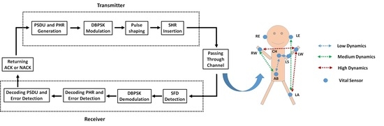
This subsection introduces the dynamic on-body UWB channel model supposed in this study [25].
Figure 4a shows the eight spots chosen on the body for the antenna locations. The test person was located in an anechoic chamber, as shown in Figure 4b. Initially, the person was standing still. He or she started to walk back and forth, changing directions randomly when the measurement was launched. In practice, the armored measurement cables and the fragile structure of the antenna connectors limited the movements to an area of approximately 1 m by 1.5 m.
The link categorization is summarized in Table 2 for the case of uniform antenna installation. The links were categorized into three groups to obtain statistical information on the dynamic channels. The links with high dynamics (HD) are links for which both antennas are placed in highly mobile locations. For the medium dynamics (MD) channels, only one antenna is attached to the end of a limb, while the other antenna is on the head or torso. For the low dynamics (LD) links, both antennas are sited on the head or torso. The cases involving the left shoulder are also categorized as LD.
It is known from the measurement results of [25] that these dynamic channels can be well fitted by the inverse Gaussian distribution. The probability density function (PDF) is expressed as follows:
f ( x | α , β ) = β 2 π x 3   exp { β 2 α 2 x ( x α ) 2 } ,   x > 0 .
Here, x is the channel impulse response (CIR), and α > 0 and β > 0 are the mean and shape parameters, respectively. Then, the cumulative distribution function (CDF) is expressed as follows:
F ( x | α , β ) = Φ ( β x α β x ) + Φ ( β x α β x ) · exp { 2 β α } ,
Φ ( x ) = 1 2 π x exp { t 2 2 } d t .
The parameter values for each category in the case of uniform loop antennas and a UWB high-band channel 6 are shown in Table 3. The numerical values in each cell are to be multiplied by a factor of 10 4 .

3.3. System Model

The system model is illustrated in Figure 5. On the transmitter side, after the PHR and PSDU are generated, they are modulated with DBPSK. Pulse shaping is applied to the modulated PHR and PSDU, and the PPDU is generated by adding the SHR to the beginning. A transmitter sends the PPDU to a receiver through the dynamic channel. On the receiver side, the receiver detects the SFD from the received PPDU. Then, DBPSK demodulation is performed on the extracted PHR and PSDU. Decoding is performed on the demodulated PHR and PSDU for error correction and detection. If no bit errors are detected, an acknowledgment (ACK) packet is sent back to the transmitter, and the transmitter sends the next PPDU. On the other hand, if bit errors are detected, a no-acknowledgment (NACK) packet is sent back to the transmitter, and the transmitter retransmits the current PPDU.
Figure 6a,b show a block diagram of the procedure for application on the error-correcting and error-detecting codes to the PHR and PSDU. Firstly, the CRC encoding of the PHR frame is carried out, and then whether to be encoded by the shortened BCH or RS code is determined. Next, it is determined whether to apply an SOCC. Similarly, the CRC encoding of the MAC header and MAC frame body is performed, and then whether to be encoded by the BCH or RS code is determined. In addition, whether to apply an SOCC is also determined. Hence, concatenated encoding with a BCH or RS code as the outer code and an SOCC as the inner code is carried out when those error-correcting codes are applied.
Here, not only a BCH or RS code but also an SOCC is applied. An SOCC has a very low coding rate and consequently possesses very strong error-correcting capabilities [38,44,45,46,47,48]. Therefore, an SOCC is compatible with UWB communication because it uses a very wide bandwidth [38,48]. The coding rate R S O C C of an SOCC is 2 ( K 2 ) . Here, K represents the constraint length.

4. Results

4.1. Computer Simulation Parameters

This section shows the performance of the IR-UWB PHY in terms of the transmission failure ratio, the energy efficiency and the average number of retransmissions as determined through computer simulations. Table 4 lists the main parameters of the computer simulations. The UWB-WBAN dynamic channel model introduced in Section 3.2 is applied as the channel model [25]. As a compared scheme, computer simulations are also performed to evaluate the case in which the (11, 5) shortened RS code and the (31, 25) RS code are used for the PHR and PSDU, respectively, as error-correcting codes with coding rates approximately equal to those of the BCH codes utilized in IEEE 802.15.6. The simulator was built by MATLAB.
The energy efficiency in the PHY is derived from [34,38,49,50,51,52] as follows:
η P s u c c L i n f o ( N ¯ + 1 ) E l i n k .
In Equation (10), E l i n k is the energy consumption of the communication link, N ¯ is the average number of retransmissions and P s u c c is the transmission success ratio. P s u c c can be expressed as follows [38,49]:
P s u c c = 1 P f a i l = 1 { P f ,   S H R + ( 1 P f ,   S H R ) P e ,   P H R + ( 1 P f ,   S H R ) ( 1 P e ,   P H R ) P e ,   P S D U } ( N m a x + 1 ) .
In Equation (11), N m a x is the maximum number of retransmissions, P f a i l is the transmission failure ratio, P f , S H R is the SFD detection failure ratio, P e ,   P H R is the PHR error ratio, and P e ,   P S D U is the PSDU error ratio. Additionally, E l i n k can be simply described as follows [38,49]:
E l i n k = L P P D U ( P t x + P r x ) / T w + ( ε e n c + ε d e c ) ,
L P P D U = L S H R + L P H R + L P S D U .
In Equations (12) and (13), L P P D U , L S H R , L P H R , and L P S D U are the lengths of the PPDU, SHR, PHR, and PSDU, respectively; P t x and P r x are the amounts of power consumed by the transmitter and receiver, respectively; and ε e n c and ε d e c are the encoding and decoding energies, respectively [34,38,49,50,51,52].

4.2. Single Pulse Option

Figure 7, Figure 8 and Figure 9 show the transmission failure ratio, energy efficiency and average number of retransmissions, respectively, as functions of the maximum number of retransmissions in the case of the single pulse option for each link type.
As the maximum number of retransmissions increases, the average number of retransmissions also increases, while the transmission failure ratio and energy efficiency improve. The reason is that the transmission success ratio increases as the maximum number of retransmissions increases. For example, the transmission failure ratio is 0.2, the energy efficiency is approximately 75 information bits per microjoule ( μ J ), and the average number of retransmissions is approximately 2.4 in case that the link type is MD, the RS code is applied, and the maximum number of retransmissions is set to five. On the other hand, the transmission failure ratio is 0.07, the energy efficiency is approximately 80 information bits per μ J , and the average number of retransmissions is approximately 3.0 when the maximum number of retransmissions is set to nine under the same conditions.
As the K value of the SOCC increases, the transmission failure ratio and the average number of retransmissions improve because the error-correcting capability increases with decreasing R S O C C . On the other hand, the energy efficiency decreases because the number of redundant bits in the is PPDU increased. Taking LD links as an example, it is necessary to set the maximum number of retransmissions to eight when error-correcting code is not applied, while the maximum number of retransmissions should be 4 when R S O C C is 1/4, and that should be two when R S O C C is 1/32 to achieve the transmission failure ratio of 10 3 . On the other hand, the energy efficiencies are approximately 145, 85, and 20 information bits per μ J when error correcting code is not applied, R S O C C is 1/4, and R S O C C is 1/32, respectively, under the above conditions. In a comparison of concatenated encoding with a BCH code and an SOCC against concatenated encoding with an RS code and an SOCC, the energy efficiency and average number of retransmissions are almost the same. However, the transmission failure ratio is more greatly improved by concatenated encoding with an RS code and an SOCC than by concatenated encoding with a BCH code and an SOCC because the error-correcting capability in the former case is larger. For example, in case that the link type is LD and R S O C C = 1/4, the maximum number of retransmissions should be set to three when concatenated with the BCH code to achieve the transmission failure ratio of 10 2 , while the maximum number of retransmissions may be set to two when concatenated with the RS code.
As seen by comparing each link type, LD links show much less performance degradation than the other link types. The transmission failure ratio for LD links is less than 10 3 even without error-correcting coding when the maximum number of retransmissions is fewer than nine. In addition, the average number of retransmissions is less than one under the same conditions. On the other hand, MD and HD links deteriorate greatly in performance in terms of each metric compared to LD links. When the maximum number of retransmissions is fewer than 10, the transmission failure ratio is below 10 2 unless R S O C C is 1/16 or less for MD links or 1/8 or less for HD links. In addition, the average number of retransmissions is required to be more than 1 for the transmission failure ratio to be less than 10 2 . Furthermore, the transmission failure ratio does not fall below 10 3 in MD links under the same conditions. Additionally, the energy efficiency of MD and HD links is less than 60% of that of LD links.

4.3. Burst Pulse Option

Figure 10, Figure 11 and Figure 12 show the transmission failure ratio, energy efficiency and average number of retransmissions, respectively, as functions of the maximum number of retransmissions in the case of the burst pulse option for each link type. Here, the processing gain N c p b R S O C C 1 is fixed at 32.
Similar to the single pulse option, LD links show significantly less performance degradation, whereas MD and HD links show greatly degraded performance in each metric. In particular, when the maximum number of retransmissions is two or fewer in LD links, the average number of retransmissions is very close to zero, and the transmission failure ratio reaches 10 3 . On the other hand, the transmission failure ratio in MD links does not reach 10 3 even when the maximum number of retransmissions is set to nine, depending on R S O C C .
Moreover, the effect of BCH or RS coding in improving the transmission failure ratio and the average number of retransmissions is large. Especially, the best performance is obtained in the case of concatenated encoding using an SOCC with R S O C C = 1/2 and an RS code. Hence, simply lowering the SOCC coding rate does not provide better performance. The reason is that miscorrections increase in frequency when decoding the SOCC in the case that the received power is insufficient.
The energy efficiency is the highest in the case of encoding using only an SOCC with R S O C C = 1/2. The performance is better than that in the case with no error-correcting encoding. This indicates that the increase in the error-correcting capability has a greater effect than that in the energy consumption for SOCC encoding and decoding. On the other hand, the transmission failure ratio and the average number of retransmissions improve while the energy efficiency decreases because of the increase in the number of redundant bits in the case that the BCH or RS code is concatenated with an SOCC. However, the difference in energy efficiency between concatenated encoding and non-concatenated encoding is about three information bits per μ J at most, which is not large.

5. Discussion

This section discusses the results obtained in the performance evaluation and possible implications of these results.
First, the difference in the performance of each link type is considered. Figure 13 plots the PDF as a function of the CIR attenuation for each link type. In the case of LD links, the CIR attenuation has a wide distribution, spanning from large to small values. Hence, the possibility of obtaining sufficient received power is high, and the deterioration in each performance metric is suppressed. On the other hand, the CIR attenuations are concentrated at small values for HD and MD links. In other words, the received power tends to be insufficient, and each performance metric greatly deteriorates. Additionally, the distribution of the CIR attenuation is more concentrated at smaller values for MD links than for HD links. Therefore, HD links can provide better performance as long as the error-correcting capability is sufficient. As shown in Figure 4a, line-of-sight (LOS) and non-line-of-sight (NLOS) conditions alternate frequently in HD links. That is, the distribution is considered to be as shown in Figure 13.
The performance evaluation and the results obtained for each link type are useful for optimizing the location of each sensor and hub when designing a UWB-WBAN. In addition, these results can be effectively used when endowing a UWB-WBAN with a multihop functionality. For example, the average numbers of retransmissions for LD, MD and HD links are approximately 0.65, 3.0, and 3.25, respectively when the maximum number of retransmissions is 9 and the RS code is applied in the single pulse option. In other words, MD or HD links communication requires about 2.5 times the transmission delay time as compared to LD links. Therefore, it is considered more efficient and highly dependable to communicate using LD links in two hops than using MD or HD links in one hop.
From the above, Optimization of the positional relationships between the sensors and hubs can lead to the realization of highly reliable and continuous communication in a UWB-WBAN. In other words, these results clarify the feasibility of achieving a stable and highly reliable IoMT environment using UWB-WBANs. As for future prospects, highly reliable IoMT based on UWB-WBAN is expected to connect with cyber physical systems (CPS) and digital twin, and to provide more advanced medical and healthcare services in smart cities [53,54].

6. Conclusions

This research has applied the dynamic on-body UWB channel model to a WBAN and demonstrated the feasibility of a high-reliability UWB-WBAN by evaluating the transmission failure ratio, energy efficiency, and average number of packet retransmissions. The numerical results have revealed the maximum number of retransmissions needed to achieve the desired transmission failure ratio for each link type and the corresponding energy efficiency and average number of retransmissions. In both single and burst pulse options, LD links have shown significantly less performance degradation, whereas MD and HD links have shown greatly degraded performance in each metric. In addition, the effectiveness of an SOCC and concatenated encoding with an SOCC and an RS code has also been shown under the dynamic channel model. As the K value of the SOCC increases, the transmission failure ratio and the average number of retransmissions have improved, while the energy efficiency has decreased since the number of redundant bits in the PPDU is increased. The optimal combination of the coding rate of the SOCC and the number of pulses in the burst pulse option case has also been clarified. Particularly, the best performance has obtained in the case of encoding using an SOCC with R S O C C = 1/2.
For future work, the cross-layer optimization of the PHY and the access protocol should be considered. Additionally, it will be necessary to consider performance evaluation in an environment with multiple UWB-WBANs and external devices utilizing UWB communication.

Author Contributions

Conceptualization, K.T. and H.T.; methodology, K.T. and H.T.; software, K.T.; validation, K.T. and H.T.; formal analysis, K.T.; investigation, K.T.; resources, K.T. and K.S.; data curation, K.T. and H.T.; writing—original draft preparation, K.T.; writing—review and editing, K.T., H.T. and K.S.; visualization, K.T.; supervision, H.T. and K.S.; project administration, K.T.; and funding acquisition, K.T. All authors have read and agreed to the published version of the manuscript.

Funding

This research was funded by a JSPS Grant-in-Aid for Early-Career Scientists, Grant Number JP20K14737.

Institutional Review Board Statement

Not applicable.

Informed Consent Statement

Not applicable.

Data Availability Statement

Not applicable.

Conflicts of Interest

The authors declare no conflict of interest.

References

  1. Gatouillat, A.; Badr, Y.; Massot, B.; Sejdić, E. Internet of Medical Things: A Review of Recent Contributions Dealing with Cyber-Physical Systems in Medicine. IEEE Internet Things J. 2018, 5, 3810–3822. [Google Scholar] [CrossRef] [Green Version]
  2. Limaye, A.; Adegbija, T. HERMIT: A Benchmark Suite for the Internet of Medical Things. IEEE Internet Things J. 2018, 5, 4212–4222. [Google Scholar] [CrossRef]
  3. Sun, L.; Jiang, X.; Ren, H.; Guo, Y. Edge-Cloud Computing and Artificial Intelligence in Internet of Medical Things: Architecture, Technology and Application. IEEE Access 2020, 8, 101079–101092. [Google Scholar] [CrossRef]
  4. Alshehri, F.; Muhammad, G. A Comprehensive Survey of the Internet of Things (IoT) and AI-Based Smart Healthcare. IEEE Access 2021, 9, 3660–3678. [Google Scholar] [CrossRef]
  5. Dwivedia, R.; Mehrotrab, D.; Chandrac, S. Potential of Internet of Medical Things (IoMT) applications in building a smart healthcare system: A systematic review. J. Oral Biol. Craniofacial Res. 2022, 12, 302–318. [Google Scholar] [CrossRef] [PubMed]
  6. Ning, Z.; Dong, P.; Wang, X.; Hu, X.; Guo, L.; Hu, B.; Guo, Y.; Qiu, T.; Kwok, R.Y. Mobile Edge Computing Enabled 5G Health Monitoring for Internet of Medical Things: A Decentralized Game Theoretic Approach. IEEE J. Sel. Areas Commun. 2021, 39, 463–478. [Google Scholar] [CrossRef]
  7. Blunda, L.L.; Gutiérrez-Madroñal, L.; Wagner, M.F.; Medina-Bulo, I. A Wearable Fall Detection System Based on Body Area Networks. IEEE Access 2020, 8, 193060–193074. [Google Scholar] [CrossRef]
  8. Mehmood, G.; Khan, M.Z.; Waheed, A.; Zareei, M.; Mohamed, E.M. A Trust-Based Energy-Efficient and Reliable Communication Scheme (Trust-Based ERCS) for Remote Patient Monitoring in Wireless Body Area Networks. IEEE Access 2020, 8, 131397–131413. [Google Scholar] [CrossRef]
  9. Moin, A.; Thielens, A.; Araujo, A.; Sangiovanni-Vincentelli, A.; Rabaey, J.M. Adaptive Body Area Networks Using Kinematics and Biosignals. IEEE J. Biomed. Health Inform. 2021, 25, 623–633. [Google Scholar] [CrossRef]
  10. Misra, S.; Bishoyi, P.K.; Sarkar, S. i-MAC: In-Body Sensor MAC in Wireless Body Area Networks for Healthcare IoT. IEEE Syst. J. 2021, 15, 4413–4420. [Google Scholar] [CrossRef]
  11. Shen, S.; Qian, J.; Cheng, D.; Yang, K.; Zhang, G. A Sum-Utility Maximization Approach for Fairness Resource Allocation in Wireless Powered Body Area Networks. IEEE Access 2019, 7, 20014–20022. [Google Scholar] [CrossRef]
  12. Javaid, S.; Zeadally, S.; Fahim, H.; He, B. Medical Sensors and Their Integration in Wireless Body Area Networks for Pervasive Healthcare Delivery: A Review. IEEE Sens. J. 2022, 22, 3860–3877. [Google Scholar] [CrossRef]
  13. Selem, E.; Fatehy, M.; El-Kader, S.M.A. mobTHE (Mobile Temperature Heterogeneity Energy) Aware Routing Protocol for WBAN IoT Health Application. IEEE Access 2021, 9, 18692–18705. [Google Scholar] [CrossRef]
  14. Ar-Reyouchi, E.M.; Ghoumid, K.; Yahiaoui, R.; Elmazria, O. Optimized Reception Sensitivity of WBAN Sensors Exploiting Network Coding and Modulation Techniques in an Advanced NB-IoT. IEEE Access 2022, 10, 35784–35794. [Google Scholar] [CrossRef]
  15. Caballero, E.; Ferreira, V.; Lima, R.A.; Soto, J.C.H.; Muchaluat-Saade, D.; Albuquerque, C. BNS: A Framework for Wireless Body Area Network Realistic Simulations. Sensors 2021, 21, 5504. [Google Scholar] [CrossRef]
  16. IEEE Standard for Information Technology—Telecommunications and Information Exchange between Systems—Local and Metropolitan Area Networks; Specific Requirements: Part 15.6: Wireless Medium Access Control (MAC) and Physical Layer (PHY) Specifications for Wireless Personal Area Networks (WPANs) Used in or 12 around a Body. 2012. Available online: https://ieeexplore.ieee.org/document/6161600 (accessed on 30 June 2022).
  17. Smart Body Area Network (SmartBAN); Low Complexity Medium Access Control (MAC) for SmartBAN. ETSI TC Smart BAN TS 103 325 V1.1.1. 2015. Available online: http://www.etsi.org/deliver/etsi_ts/103300_103399/103325/01.01.01_60/ts_103325v010101p.pdf (accessed on 30 June 2022).
  18. Smart Body Area Network (SmartBAN); Enhanced Ultra-Low Power Physical Layer. ETSI TC Smart BAN TS 103 326 V1.1.1. 2015. Available online: https://www.etsi.org/deliver/etsi_ts/103300_103399/103326/01.01.01_60/ts_103326v010101p.pdf (accessed on 30 June 2022).
  19. Sanguanpuak, C.; Bunlaksananusorn, C.; Promwong, S. Distortion Analysis of the HB-UWB Transmission Waveform for WBAN Applications. In Proceedings of the 2018 Global Wireless Summit (GWS), Chiang Rai, Thailand, 25–28 November 2018. [Google Scholar]
  20. Mahmood, S.N.; Ishak, A.J.; Ismail, A.; Soh, A.C.; Zakaria, Z.; Alani, S. ON-OFF Body Ultra-Wideband (UWB) Antenna for Wireless Body Area Networks (WBAN): A Review. IEEE Access 2020, 8, 150844–150863. [Google Scholar] [CrossRef]
  21. Elhelbawy, M. Wireless Body Area Networks UWB Antenna Design and Channel Modeling. In Proceedings of the 2020 International Applied Computational Electromagnetics Society Symposium (ACES), Monterey, CA, USA, 27–31 July 2020. [Google Scholar]
  22. Balevi, E.; Gitlin, R.D. Stochastic geometry analysis of IEEE 802.15.6 UWB WBAN performance with game theoretical power management. In Proceedings of the 2018 IEEE 19th Wireless and Microwave Technology Conference (WAMICON), Sand Key, FL, USA, 9–10 April 2018. [Google Scholar]
  23. Zilani, T.A.; Al-Turjman, F.; Khan, M.B.; Zhao, N.; Yang, X. Monitoring Movements of Ataxia Patient by Using UWB Technology. Sensors 2020, 20, 931. [Google Scholar] [CrossRef] [Green Version]
  24. Kumpuniemi, T.; Hämäläinen, M.; Tuovinen, T.; Yazdandoost, K.Y.; Iinatti, J. Radio channel modelling for pseudo-dynamic WBAN on-body UWB links. In Proceedings of the 2014 8th International Symposium on Medical Information and Communication Technology (ISMICT), Firenze, Italy, 2–4 April 2014. [Google Scholar]
  25. Kumpuniemi, T.; Hämäläinen, M.; Yazdandoost, K.Y.; Iinatti, J. Dynamic on-body UWB radio channel modeling. In Proceedings of the 2015 9th International Symposium on Medical Information and Communication Technology (ISMICT), Kamakura, Japan, 24–26 March 2015. [Google Scholar]
  26. Kumpuniemi, T.; Hämäläinen, M.; Yazdandoost, K.Y.; Iinatti, J. Categorized UWB on-Body Radio Channel Modeling for WBANs. Prog. Electromagn. Res. B 2016, 67, 1–16. [Google Scholar] [CrossRef] [Green Version]
  27. Kosz, P.T.; Ambroziak, S.J.; Stefanski, J.; Cwalina, K.K.; Correia, L.M.; Turbic, K. An Empirical System Loss Model for Body Area Networks in a Passenger Ferry Environment. In Proceedings of the Baltic URSI Symposium, Poznan, Poland, 14–17 May 2018. [Google Scholar]
  28. van Roy, S.; Quitin, F.; Liu, L.; Oestges, C.; Horlin, F.; Dricot, J.M.; Doncker, P.D. Dynamic Channel Modeling for Multi-Sensor Body Area Networks. IEEE Trans. Antennas Propag. 2013, 61, 2200–2208. [Google Scholar] [CrossRef]
  29. Maskooki, A.; Soh, C.B.; Gunawan, E.; Low, K.S. Ultra-Wideband Real-Time Dynamic Channel Characterization and System-Level Modeling for Radio Links in Body Area Networks. IEEE Trans. Microw. Theory Tech. 2013, 61, 2995–3004. [Google Scholar] [CrossRef]
  30. Yazdandoost, K.Y.; Sayrafian-Pour, K. Channel Model for Body Area Network (BAN). IEEE P802.15 Working Group for Wireless Personal Area Networks (WPANs), IEEE P802.15-08-0780-10-0006. 2009. Available online: https://mentor.ieee.org/802.15/file/08/15-08-0780-10-0006-tg6-channel-model.pdf (accessed on 4 July 2022).
  31. Dautov, R.; Tsouri, G.R. Dynamic Off-Body Rician Channel Modeling for Indoor Wireless Body Area Networks. IEEE J. Biomed. Health Inform. 2020, 24, 1246–1254. [Google Scholar] [CrossRef] [PubMed]
  32. Liu, J.; Shao, Y.; Wang, P.; Zhang, J. Dynamic Channel Modeling of WBAN at 28 GHz. In Proceedings of the 2020 IEEE International Symposium on Antennas and Propagation and North American Radio Science Meeting, Montreal, QC, Canada, 5–10 July 2020. [Google Scholar]
  33. Decawave Application Note: APR 001. UWB Regulations—A Summary of Worldwide Telecommunications Regulations Governing the Use of Ultra-Wideband Radio. 2018. Available online: https://www.decawave.com/sites/default/files/apr001_uwb_worldwide_regulations_summaryrev1.2.pdf (accessed on 11 January 2022).
  34. Karvonen, H.; Iinatti, J.; Hämäläinen, M. A cross-layer energy efficiency optimization model for WBAN using IR-UWB transceivers. Telecommun. Syst. 2015, 58, 165–177. [Google Scholar] [CrossRef]
  35. Jajodia, B.; Shaik, R.A.; Mahanta, A. PPM demodulation schemes for IEEE 802.15.6 IR-UWB WBAN receivers. In Proceedings of the 2015 IEEE International Conference on Signal Processing, Informatics, Communication and Energy Systems (SPICES), Kozhikode, India, 19–21 February 2015. [Google Scholar]
  36. Ding, J.; Dutkiewicz, E.; Huang, X. Performance evaluation of virtual MIMO for UWB based body area networks. In Proceedings of the 2013 7th International Symposium on Medical Information and Communication Technology (ISMICT), Tokyo, Japan, 6–8 March 2013. [Google Scholar]
  37. Takabayashi, K.; Tanaka, H.; Sugimoto, C.; Sakakibara, K.; Kohno, R. Performance Evaluation of Quality of Service Control Scheme in Multi-hop WBAN Based on IEEE 802.15.6. Sensors 2018, 18, 3969. [Google Scholar] [CrossRef] [PubMed] [Green Version]
  38. Takabayashi, K.; Tanaka, H.; Sakakibara, K. Toward Dependable Internet of Medical Things: IEEE 802.15.6 Ultra-Wideband Physical Layer Utilizing Superorthogonal Convolutional Code. Sensors 2022, 22, 2172. [Google Scholar] [CrossRef] [PubMed]
  39. Choudhury, N.; Matam, R.; Mukherjee, M.; Lloret, J. A Performance-to-Cost Analysis of IEEE 802.15.4 MAC With 802.15.4e MAC Modes. IEEE Access 2020, 8, 41936–41950. [Google Scholar] [CrossRef]
  40. Moravejosharieh, A.; Lloret, J. Performance evaluation of co-located IEEE 802.15.4-based wireless body sensor networks. Ann. Telecommun. 2016, 71, 425–440. [Google Scholar] [CrossRef]
  41. Niemelä, V.; Hämäläinen, M.; Iinatti, J. On IEEE 802.15.6 IR-UWB receivers—Simulations for DBPSK modulation. In Proceedings of the 2013 35th Annual International Conference of the IEEE Engineering in Medicine and Biology Society (EMBC), Osaka, Japan, 3–7 July 2013. [Google Scholar]
  42. Jajodia, B.; Shaik, R.A.; Mahanta, A. Demodulation techniques for IEEE 802.15.6 IR-UWB DBPSK WBAN transceivers. In Proceedings of the 2015 IEEE 3rd International Conference on Smart Instrumentation, Measurement and Applications (ICSIMA), Kuala Lumpur, Malaysia, 24–25 November 2015. [Google Scholar]
  43. Takabayashi, K.; Karvonen, H.; Paso, T.; Tanaka, H.; Sugimoto, C.; Kohno, R. Performance Evaluation of a QoS-aware Error Control Scheme for Multiple-WBAN Environment. IEEJ Trans. Electr. Electron. Eng. 2017, 12, S146–S157. [Google Scholar] [CrossRef]
  44. McEliece, R.; Dolinar, S.; Pollara, F.; Van Tilborg, H. Some easily analyzable convolutional codes. Telecommun. Data Acquis. Report. 1989, 42, 105–114. [Google Scholar]
  45. Johannesson, R.; Zigangirov, K.S. Fundamentals of Convolutional Coding, 2nd ed.; Wiley-IEEE Press: Hoboken, NJ, USA, 2005; pp. 593–626. [Google Scholar]
  46. Frenger, P.; Orten, P.; Ottosson, T. Code-spread CDMA using maximum free distance low-rate convolutional codes. IEEE Trans. Commun. 2000, 48, 135–144. [Google Scholar] [CrossRef] [Green Version]
  47. Viterbi, A.J. Very low rate convolution codes for maximum theoretical performance of spread-spectrum multiple-access channels. IEEE J. Sel. Areas Commun. 1990, 8, 641–649. [Google Scholar] [CrossRef] [Green Version]
  48. Matsumoto, T.; Kohno, R. Performance of Super-Orthogonal Convolutional Coding for Ultra-Wideband Systems in Multipath and Multiuser Channels. Wirel. Pers. Commun. 2007, 40, 355–370. [Google Scholar] [CrossRef]
  49. Takabayashi, K.; Tanaka, H.; Sakakibara, K. Toward an Advanced Human Monitoring System Based on a Smart Body Area Network for Industry Use. Electronics 2021, 10, 688. [Google Scholar] [CrossRef]
  50. DWM1001 Datasheet, Decawave Ltd., Ver. 1.10. 2017. Available online: https://www.decawave.com/wp-content/uploads/2019/01/DWM1001_Datasheet-1.4.pdf (accessed on 11 January 2022).
  51. Abughalieh, N.; Steenhaut, K.; Now´e, A.; Anpalagan, A. Turbo codes for multihop wireless sensor networks with de-code-and-forward mechanism. EURASIP J. Wirel. Commun. Netw. 2014, 204, 1–13. [Google Scholar]
  52. Goel, M.; Shanbhag, N.R. Low-power channel coding via dynamic reconfiguration. In Proceedings of the 1999 IEEE Interna-tional Conference on Acoustics, Speech, and Signal Processing, ICASSP99, Phoenix, AZ, USA, 15–19 March 1999. [Google Scholar]
  53. Khan, S.; Arslan, T.; Ratnarajah, T. Digital Twin Perspective of Fourth Industrial and Healthcare Revolution. IEEE Access 2022, 10, 25732–25754. [Google Scholar] [CrossRef]
  54. Bhatti, D.S.; Saleem, S.; Imran, A.; Iqbal, Z.; Alzahrani, A.; Kim, H.; Kim, K.-I. A Survey on Wireless Wearable Body Area Networks: A Perspective of Technology and Economy. Sensors 2022, 22, 7722. [Google Scholar] [CrossRef]
Figure 1. Operating frequency bands for the IEEE 802.15.6 UWB PHY.
Electronics 11 03491 g001
Figure 2. PPDU structure.
Electronics 11 03491 g002
Figure 3. Signal transmission example in the case of the burst pulse option.
Electronics 11 03491 g003
Figure 4. (a) On-body antenna locations. (b) Test person’s motions.
Electronics 11 03491 g004aElectronics 11 03491 g004b
Figure 5. Block diagram representing the system model.
Electronics 11 03491 g005
Figure 6. (a) PHR construction for transmission. (b) PSDU construction for transmission.
Electronics 11 03491 g006aElectronics 11 03491 g006b
Figure 7. Transmission failure ratio as a function of the maximum number of retransmissions in the case of the single pulse option for each link type: (a) LD, (b) MD, and (c) HD.
Electronics 11 03491 g007aElectronics 11 03491 g007b
Figure 8. Energy efficiency as a function of the maximum number of retransmissions in the case of the single pulse option for each link type: (a) LD, (b) MD, and (c) HD.
Electronics 11 03491 g008aElectronics 11 03491 g008b
Figure 9. The average number of retransmissions as a function of the maximum number of retransmissions in the case of the single pulse option for each link type: (a) LD, (b) MD, and (c) HD.
Electronics 11 03491 g009aElectronics 11 03491 g009b
Figure 10. Transmission failure ratio as a function of the maximum number of retransmissions in the case of the burst pulse option with N c p b R S O C C 1 = 32 for each link type: (a) LD, (b) MD, and (c) HD.
Electronics 11 03491 g010aElectronics 11 03491 g010b
Figure 11. Energy efficiency as a function of the maximum number of retransmissions in the case of the burst pulse option with N c p b R S O C C 1 = 32 for each link type: (a) LD, (b) MD, and (c) HD.
Electronics 11 03491 g011aElectronics 11 03491 g011b
Figure 12. The average number of retransmissions as a function of the maximum number of retransmissions in the case of the burst pulse option with N c p b R S O C C 1 = 32 for each link type: (a) LD, (b) MD, and (c) HD.
Electronics 11 03491 g012aElectronics 11 03491 g012b
Figure 13. PDF as a function of the CIR attenuation in the case of each link type.
Electronics 11 03491 g013
Table 1. Mapping of information bits onto φ m for DBPSK.
g m φ m
00
1 π
Table 2. Link categorization.
Link Type
HDMDLD
RW-LA, LA-LW, RW-LWLA-LE, LA-RE, AB-LW, CH-LWLE-RE, AB-CH, AB-LS, CH-LS, LW-LS
Table 3. Link categorization.
Link Type
HDMDLD
Parameter 10 4 10 4 10 4
α 10.2626.8867.09
β 2.221.3010.23
Table 4. Computer simulation parameters.
ParameterDetails
Channel modelUWB-WBAN dynamic channel model [25]
Link typeLD, MD, HD
Center frequency7987.2 MHz
Bandwidth ( BW )499.2 MHz
ModulationDBPSK
Forward error correction (PHR)(40, 28) shortened BCH code, (11, 5) shortened RS code, SOCC ( K = 3 ~ 7 )
Forward error correction (PSDU)(63, 51) BCH code, (31, 25) RS code, SOCC ( K = 3 ~ 7 )
Power spectral density emission ( G l i m )−41.3 dBm/MHz
Thermal noise density ( N 0 )−174 dBm/Hz
Implementation loss ( I dB )3 dB
Receiver noise figure ( N F dB )5 dB
Information bit length ( L i n f o )540 bits
Duration of p ( t ) ( T p )2.003 ns
Pulse optionSingle pulse option, burst pulse option
Uncoded symbol rate of the single pulse option ( R S )7.8 Msps
Maximum number of retransmissions ( N m a x )1~9
N c p b 1, 2, 4, 8, 16, 32
Publisher’s Note: MDPI stays neutral with regard to jurisdictional claims in published maps and institutional affiliations.

