Abstract
This paper proposes a novel image large rotation and scale estimation method based on the Gabor filter and pulse-coupled neural network (PCNN). First, the Gabor features of the template image and its rotated one are extracted by performing the Gabor filter. Second, we present a modified PCNN model to measure the similarity between the Gabor features of the image and its rotated one. Finally, the rotation angle is calculated by searching the global minimum of the correlation coefficients. Besides rotation estimation, we also propose a scale estimation method based on the max-projection strategy. The Gabor feature image is projected along the estimated rotation angle, and the scale is calculated by searching the peak of this projection result. Moreover, experiments illustrate that the proposed method has high accuracy on rotation and scale estimation and is robust to noise. Compared with the state-of-the-art methods, the proposed approach has a more stable performance.
1. Introduction
With the development of science and technology, there is a higher and higher demand for image processing. When two or more images are used to obtain common information, oftentimes, it is necessary to perform image registration such as rotation, shifting, and scaling. Image registration is widely used in image stitching [1], image fusion [2], motion estimation [3], object recognition, and so on [4,5].
Electronic video stabilization is based on the correlation of image information between frames of video image sequences, and the estimation of rotational motion is one of the core technologies of electronic video stabilization. UAVs suffer from aerodynamics in the process of reconnaissance, resulting in large angle rotation and jitter in the video, so they cannot complete the task of reconnaissance and target identification [6,7]. Therefore, achieving large angle rotation estimation is an urgent problem to solve. Remote sensing and mapping, medical diagnosis, industrial production, and other fields have a high demand for panoramic images [8,9]. To address this demand, the approach of stitching multiple images with duplicate areas to obtain a panoramic image has been created. Estimating the rotation angle between two images is an essential prerequisite. Visual odometry is a technique for estimating camera trajectories in continuous images and is the cornerstone of visual simultaneous localization and mapping [10]. Cameras are low-cost and easy to integrate everywhere [11], so visual odometry is currently popular. In autonomous localization and navigation of robots, UAVs, and unmanned vehicles, motion estimation is a prerequisite. Therefore, camera motion estimation is an important part of SLAM, and camera motion estimation includes rotation and translation estimation. Therefore, the study of rotation estimation is very important.
The crucial work to image registration is rotation, scale, and shift estimation between two or more different images without prior knowledge. Over the past decades, various image registration methods have been proposed. High precision and large rotation with complex motion make estimation a complicated problem, especially in low-power devices. Meanwhile, many rotation and scale estimation approaches have been proposed for different images, especially for high-precision estimation. Among the existing methods, the transform-based method [12,13,14], feature-based method [15,16], and phase-only correlation (POC) method [3] have been widely used in all aspects of image rotation, scale, and shift estimation.
The transform-based method is an algorithm that converts the image’s rotation and scale estimation to a shift estimation of other domains and estimates shift using existing methods [17]. Conventional transforms used for angle, scale, and shift estimation are Radon [13,14], Fourier–Mellin [12], log-polar [18], and Hough. Log-polar, Radon, and Hough transform convert the rotation into the geometrical shift, and the transformed image can be determined by projecting or function transformation. However, the precision of the rotation estimation is limited to the projection angle spacing. The Fourier–Mellin method separates the geometrical shift by Fourier transformation and transforms the amplitude spectrum to log-polar coordinates. Therefore, all the estimations can be converted into the geometrical shift estimation, whose computation speed is limited to the transform efficiency. The transform-based approaches usually take a relatively long time because they are based on pixel processing. The feature-based methods compare two images by the key points and obtain a transform matrix using the matched key points, separating the rotation, scale, and shift from the transform matrix using the existing method [19,20,21]. Although the feature-based method is robust to noise, the estimation precision is restricted by the number of feature points and their accuracy. One of the most common image shift estimation methods is POC. When the rotation and scale can be converted into the geometrical shift, the final results can be calculated using POC. The shift is calculated by searching the peak of the cross-power spectrum of two images. Thus, the wrong peaks can cause large errors, and this method is sensitive to spectrum aliasing.
Rotation and scale estimation between images is crucial for image processing. Current research is mainly based on traditional methods; some estimation methods [22,23,24] need to give initial estimates, and such initial estimates are difficult to achieve in complex systems. The transformation-based method [12,13,14] is relatively complex, and the transformation requires relatively more time, while the final result is limited to the efficiency of the transformation. The feature-point-based method [15,16] requires extracting and matching feature points, which is time consuming while calculating the transformation matrix between images and decomposing to obtain the rotation angle. Meanwhile, it is challenging to estimate large rotation estimation in some methods [25,26].
To address the above issues, this paper proposes a robust and novel method for rotation and scale estimation, which does not require an initial estimate. The proposed method is based on the Gabor filter and pulse-coupled neural network (PCNN). Since the image’s unique texture and orientation information can be extracted using the Gabor filter [27,28], we estimated the rotation angle by comparing the orientation features between the template image and its rotated one. This Gabor-filter-based approach makes it possible to estimate large angles. Furthermore, this paper designed a modified PCNN (mPCNN) model to measure the similarity between two feature images. The proposed measuring similarity approach is robust to noise, scale, rotation, and shift. We can estimate the final rotation angle by searching the global maximum correlation coefficient. In the scale estimation, the Gabor feature image is projected along the rotation angle using the max-projection strategy. The image scale can be estimated by searching the peak of these projection results. In addition, the experiment results demonstrated the accuracy of the proposed estimation approach and its robustness to noise. The three contributions of this study are summarized as follows:
- This paper introduces a novel estimation method for scale and rotation using the Gabor filter and PCNN.
- We designed a modified PCNN model for measuring similarity, which is robust against rotation, shift, and translation.
- This paper presents a novel method for scale estimation based on the Gabor feature image.
This paper is organized as follows. Section 2 shows the conventional approaches for rotation and scale estimation. Section 3.1 gives a brief description of the Gabor filter and the different orientation feature extraction methods using the Gabor filter. Section 3.2 describes the modified PCNN model and how to measure the similarity between the Gabor features. In Section 3.3, the details of rotation estimation are described. In Section 3.4, the scale estimation method using the Gabor features is described. Section 4 presents the comparison experiments with the other approaches. Finally, Section 5 shows the conclusion.
2. Related Works
The transformation-based method is the one with high accuracy among all methods [22,29,30,31]. Chen et al. [29] proposed a motion estimation method based on the Fourier–Mellin transformation, and the proposed approach extends the phase correlation method to estimate both rotation and translation. Giarra et al. [30] explored the particle image velocimetry method in regions with large velocity gradients or high rates of rotation and introduced a new PIV approach based on the Fourier–Mellin transformation. Compared to traditional methods, the new algorithm significantly improved the velocity estimates in previously unresolvable regions of large rotation. Pan et al. [22] proposed a rotation estimation method, which is an automated initial guess estimation. Unlike the conventional image correlation technique, Pan’s method does not acquire an accurate initial value. Xu et al. [31] presented a novel geometric visual rotation estimation method for omnidirectional cameras, which includes two parts: motion vector extraction and sinusoid fitting. This method converts the rotation estimation problem into a sinusoidal fitting problem with offsets in the image row and column directions. The rotation vectors are first extracted by finding the pixel deviations in the row and column directions, and then, the obtained rotation vectors are fit to two sinusoidal functions. This method introduces the optical flow method to extract motion vectors based on the Fourier–Merlin transform, which can meet certain accuracy requirements, but the motion tracking based on the optical flow method is not suitable for the case of large inter-frame image motion.
A group of line pencils can be denoted as using the Radon transform, which is widely used in line detection. The Radon-based method is widely used in rotation estimation [13,14,17,32,33]. Wan et al. [17] used the Radon transform for rotation estimation and converted the rotation into the shift, which was estimated using the phase correlation approach. To improve the precision of the estimation result, Fujisawa et al. [14] introduced a high-accuracy rotation estimation method based on the Radon transform. This method splits the final estimation value into an integer component and a decimal component, using the conventional POC to calculate the integer component, and estimates the decimal component by modifying the minimization function. However, The proposed approach applies the Radon transform to the frequency domain of the image, which means that the two complex transformations would reduce the time efficiency.
With the continuous development of computer equipment, pose estimation based on neural networks [34,35] also continues to develop. The separation of rotation and translation estimation is more common in neural network approaches. Kim et al. [34] presented a convolutional neural network, which was used for regressing the camera rotation. The proposed method uses a derotation operation of the spherical optical flow on a unit sphere and is fully self-supervised. Their method achieves comparable performance to fully supervised methods in rotation estimation. Zhang et al. [35] proposed a top-down prediction-based approach for rotation estimation, and an energy-based formulation was used to represent the rotation distribution of the camera. Their experiments illustrated that their approach outperforms the state-of-the-art simultaneous localization and mapping methods. Meanwhile, a series of 6D pose estimation [36,37] methods has also been proposed. The input data are usually an RGB-D image in these 6D pose estimation methods. Robust and accurate 6D pose estimation is very important for many robotics applications.
Gao et al. [36] presented a convolutional neural network method for 6D estimation. To obtain a 6D pose, depth information contained in the input data must be analyzed in an appropriate way. Gao et al. used depth information as the input to the networks and used separate networks for rotation regression. Finally, the rotation is represented by the axis angle. Another part of the method [37,38] extracts the feature information of the image using the deep network to estimate the pose. The method in [38] first detects 2D keypoints and solves a perspective-n-point problem for their 6D pose. Chen et al. [37] proposed a fast shape-based network to solve the problem of inefficient category-level pose feature extraction. They designed an orientation-aware autoencoder with 3D graph convolution for latent feature extraction. The rotation information was decoded from the latent feature using a novel decoupled rotation mechanism.
Pulse-coupled neural networks have a good performance in the field of processing the digital signal images, derived from the band synchronization of pulse-coupled biological oscillators. Johnson et al. [39] developed the first PCNN, and in [40], Kinser et al. proposed the classical PCNN. PCNN has been widely used in image fusion [41], image segmentation, image restoration, and image enhancement [42]. Klar et al. [43] proposed an image object separation using the PCNN algorithm sped up by the designed integrated circuit, and a modified PCNN with synaptic plasticity was applied to image segmentation. Due to the inherent property of PCNN, the output pulse image of PCNN is an invariant feature that is robust to noise and geometrical variations. Based on the ability of the invariant feature, many PCNN-based methods of feature extraction [44] and texture retrieval [45,46] have been studied.
3. Proposed Algorithm
A fast and simple rotation angle estimation algorithm must be proposed to improve rotation estimation efficiency and estimate the large rotation angle. The Gabor filter is a linear filter for image texture analysis. Given that its descriptions of frequency and direction are similar to the human visual system, it is widely used to obtain image texture features, edge detection, and image smoothing. PCNN is a single-layer network without any training needed. It has a pulse synchronization characteristic in the neurons with similar pixel intensities, so it is applied to image segmentation, image enhancement, feature extraction, and image fusion. Inspired by the Gabor filter and PCNN, we propose a new image rotation estimation algorithm using the Gabor filter and PCNN. The proposed method applies the Gabor filter to obtain different orientation features, which are called the Gabor features, and PCNN to calculate the similarity between the Gabor features. The whole schematic of the proposed algorithm to obtain the rotation angle and scale is illustrated in Figure 1.
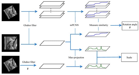
Figure 1.
Schematic diagram of the proposed algorithm.
3.1. Gabor Features
In this section, we introduce the Gabor filter and how to extract the Gabor features of an image using the Gabor filter.
3.1.1. Gabor Filter
The Gabor filter is a plane wave multiplied bya Gaussian function. In this paper, we used the the cosine function instead of the plane wave. The generating Gabor function can be defined as follows (for further details, we refer to [47]):
where
where denotes the set of image points, represents the standard deviation of the Gaussian function, and is a numeric vector that defines the ratio of the semi-major and semi-minor axes of the Gaussian envelope. represents an adjustable parameter of the cosine function. is the rotation angle of the parallel stripes in the Gabor filter kernel.
3.1.2. Gabor Feature
The Gabor filter has been successfully applied to extract local image texture features of different scales and orientations [28,47,48]. The Gabor features were used to estimate the rotation angle between the template image and the rotated image in this paper. Typically, an input image is convolved with a 2D Gabor filter at angle , and the Gabor feature of the input image at angle can be defined as follows:
where denotes the Gabor feature image at orientation ; thus, we can obtain all the Gabor features of the input image I at all orientations from to . Let denote the Gabor feature at orientation , and the input image I with all Gabor features can be defined as follows:
In the above formula, we can make sense of it as follows: every image can be decomposed into a series of Gabor feature images, and each feature image is different from the others. Therefore, theoretically, by comparing the Gabor features of the two images, it is possible to estimate the rotation angle with high accuracy. Figure 2 illustrates the Gabor filters (the first row) at six different orientations and image Gabor features (the second row) with six different orientations.
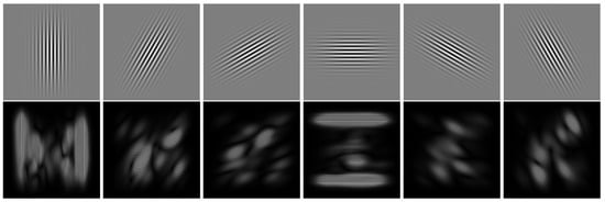
Figure 2.
The Gabor feature images with different orientations. The first row shows the Gabor filters with 6 different orientations, and the second row shows the Gabor feature image corresponding to the first row.
3.2. Computation of the Measuring Similarity
This section presents a measuring similarity method with an improved PCNN, and the method can be divided into two parts: (1) design and apply improved PCNN to extract PCNN-based features from the Gabor features; (2) measure the similarity by calculating the difference between the two PCNN-based features.
3.2.1. PCNN-Based Feature Extraction Method
It is known that PCNN is widely used in image processing as show in Figure 3, and every neuron in PCNN is equal to each pixel in the image. Hence, the input image size determines the PCNN size. The PCNN model can classify neurons with similar properties into one category because each neuron has a different firing time. The intensity of similar pixels is expected to be different from the other pixels. Thus, PCNN has a good performance on image segmentation, texture extraction, image denoising, and other applications [41,46]. Derived from the above, we propose a modified PCNN (mPCNN) model that extracts PCNN-based features from the Gabor features. The mPCNN model is defined as follows:
where n is the discrete time, each neuron is denoted with indices , and denotes the neighboring neuron of . S represents the external input stimulus of the neuron. W is the feeding synaptic weight reflecting the active neurons’ relationship. U denotes the internal membrane potential of the neuron, and T is the dynamic threshold of the network. Y stands for the pulse output of the neuron as the action potential. G denotes the time series matrix, which records the number of neurons with similar attributes, and P is named as a PCNN-based feature; it is also a 1D feature. and define the attenuation time constants of U and T, respectively.
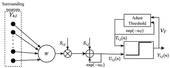
Figure 3.
The modified PCNN model.
The mPCNN model can convert all the Gabor feature images from 2D to 1D, and the external input stimulus S is equal to the intensity of the Gabor feature image pixels. Like the histogram of an image, records the number of image pixels with a similar value. However, is a simplified version of the image histogram, which is an vector (N is usually less than 256 [12]), and it is more robust against the effect of noise. The important properties of the output of this model are the translation, scale invariance, and rotational shift stated, and such properties can be exploited to estimate the similarity between two PCNN-based features.
Figure 4 shows the PCNN-based features of an input image and its rotated images. The first row of images is the original images and their rotated images with different scales, and the second row of images is the PCNN-based features corresponding to the first row of images. As shown in Figure 4, the PCNN features are assemblable when the original input images rotate at different angles and with different scales.
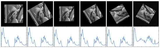
Figure 4.
The PCNN-based features. The first row shows the template images, and the second row shows the PCNN-based features corresponding to the first row. (The rotation angle of each image from left to right is , , , , , and , respectively. The scale of each image from left to right is 1, 1, 0.8, 0.8, 0.8, and 0.8, respectively. The white Gaussian noise with a given standard deviation was added to the last image.)
3.2.2. Measuring the Similarity
Assume that there are two PCNN-based features, and . The correlation coefficient C between and can be obtained using the following function:
3.3. Rotation Estimation Based on the Gabor Features
As we know, the PCNN-based feature is invariant to scale, shift, and rotation, as Figure 4 illustrates. If the Gabor features at all orientations can be obtained, then it is theoretically possible to estimate the rotation angle. Assume that I is a template image and image R is a rotated image with a rotation angle of relative to image I. Let and be, respectively, the Gabor features of image I and image R, which can be found in Equation (4). and denote the PCNN-based features of image I and image R corresponding to and , respectively. The rotation angle between image I and image R is given by
where
where denotes the PCNN-based feature of image I at the orientation and is a constant value. is the PCNN-based feature of image R at orientation , and . When and are the input stimulus of mPCNN, then and will be output. If is greater than 0, it indicates that the rotated image is rotated clockwise relative to the template image. Otherwise, it is rotated counterclockwise.
In our method, we can extract the Gabor features of the rotated image at all orientations, and all the orientations are continuous, theoretically. However, in practice, the orientation angle is discrete. Therefore, in order to obtain more accurate results, the method to estimate the rotation angle in our study consists of two steps: coarse estimation and refinement estimation. In the first step, the coarse estimation can locate the rotation angle in a small range, and this will decrease the computation. After obtaining the rough rotation angle, the second step of refinement estimation can calculate the fine angle with higher accuracy. The whole process of the proposed method is to estimate the rotation angle in two steps, as shown in Algorithm 1. The details can be expressed as follows:
| Algorithm 1: Rotation estimation. |
 |
Coarse estimation:
First, compute the Gabor feature of image I at angle and of image R at angle , according to Equation (4).
Second, after obtaining the Gabor features, compute the PCNN-based features and with, respectively, and as he input stimulus, as shown in Equation (9).
Finally, calculate the correlation coefficient between and by Equation (12), so we can obtain the similarity values between the Gabor feature with the orientation angle of image I and the Gabor features with the orientation angle , of the rotated image R. Then, calculate the rotation angle between image I and the rotated image R by searching the minimum correlation coefficients, as in Equation (13).
As discussed above, the precision of the rotation angle depends on the step angle . Thus, in the coarse the estimation experiment, is usually set to a larger value to reduce the computation. Assume that, when , the coarse rotation angle . However, this is not a high-precision result because is a large step. Meanwhile, the final rotation angle is limited to the range , and the coarse estimation limits the range of the true rotation angle from a large range to a small range with less computation.
Refinement estimation: Finding the refine rotation angle could also use the same procedure; different from the coarse estimation, is a small value for high precision in this step. A more precise rotation angle can be computed by the above procedures. In the actual calculation process, due to the discontinuity of PCNN-based features, we are unable to obtain a completely consistent estimation angle. Perform interpolation operations near to obtain the final result . The accuracy in rotation estimation depends on ; within the scope of similarity measurement, the smaller , the higher the accuracy of the result, and vice versa.
3.4. Gabor-Filter-Based Scale Estimation
After obtaining the rotation angle using the rotation estimation described in the previous section, if a 2D shift is not taken into account, the rotation angle and scale S can be expressed as follows:
The equation means that the scale of the two images is expressed as the scale of two Gabor features. The Gabor filter is modulated by a Gaussian function and a sinusoidal plane wave. A unique property of the Gabor filter is that each Gabor filter only allows the texture corresponding to its frequency to pass smoothly; such a property can be exploited to estimate between two images. Inspired by the gray projection algorithm, we propose a scale estimation method based on the max-projection strategy. The Gabor feature is projected in the direction of , which forms a one-dimensional sequence by the max projection strategy.
where and are as shown in Equations (2) and (3), respectively. is the Gabor feature at orientation , and denotes the max value of all pixels in row . We express as the projected result of and as the projected result of , as in Equation (14), respectively. Figure 5 illustrates the projection results.
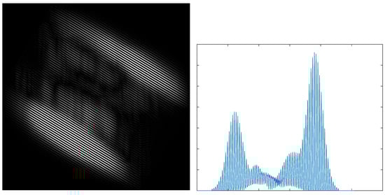
Figure 5.
The Gabor feature image (left) and its maximum value projection (right).
Using the max-projection strategy, the scale S can be obtained by the curves of and . In other words, we express as the horizontal coordinate whose value is the first peak value and as the horizontal coordinate whose value is the second peak value. Similarly, we express as the first coordinate whose value is the first peak value and as the horizontal coordinate whose value is the second peak value. Then, the proposed method obtains the estimated scale S as follows:
4. Experimental Results and Discussion
4.1. Experimental Settings
To evaluate the estimation precision of the proposed algorithm, we performed numerical experiments for a series of standard images. The rotated images were rotated and scaled with a specified angle and scale, and the error between the estimated angle and ground-truth values was considered using the estimation algorithm. The compared methods for rotation and scale estimation include SURF [15], BRISK [16], and Fourier–Mellin [18]. SURF and BRISK are feature-point-based rotation and scale estimation methods, which estimate the rotation angle and scale by resolving the position between the matched feature points. The Fourier–Mellin method estimates the rotation angle and scale in the frequency domain of the image; the key of Fourier–Mellin is to covert the rotation and scale into translation estimation, and the rotation angle and scale can be obtained by log-polar transformation. It is the fastest of the existing rotation-invariant image rotation and scale estimation algorithms [49].
The test images used in our experiments were taken from the image processing database [50]. The 12 images are of size and contain different scenes (e.g., people, trees, animals, fruits). Our experiments compared the rotation and scale copies derived from the original image. This procedure completely controls the value of the rotation angle and scale. Besides the fixed rotation angle and scale estimation, the white Gaussian noise with a given standard deviation was added to the original images to evaluate the robustness of the estimation method. First, the estimation precisions of the fixed rotation angle and the fixed scale were tested. Second, the images that were rotated from to at a step of and transformed from the scale of 0.5 to 1 at a step of 0.05 were tested. Note that “N/A” in all tables indicates that the value is unavailable.
4.2. Rotation Estimation Error
Each of the 12 images with different noises was tested individually. Table 1 and Table 2 illustrate the rotation angle estimation errors at fixed angles of and , respectively. For the purpose of analysis, the absolute values of the error are shown in all tables. Table 1 shows the small rotation angle () estimation errors. The angle errors of all methods except SURF are less than . The proposed method and Fourier–Mellin have similar performance in all images and perform better than all the other methods in the small rotation angle test. When the white Gaussian noise (standard deviation ) is applied, our approach demonstrates superior robustness, with the error being less than . Table 2 illustrates the large rotation angle () estimation errors. The proposed method demonstrates good immunity to interference. The estimation error of the noise image is close to the estimation error of the no-noise image. Meanwhile, the proposed method did not show any abnormal rotation values.

Table 1.
Comparison of fixed rotation angle estimation errors; the rotation angle is (degrees).
Table 2.
Comparison of fixed degree estimation errors; the rotation angle is (degrees).
Figure 6 and Figure 7 compare the rotation angle errors of the Lena image with no noise and , respectively. The proposed method achieves a higher estimation precision and is more robust against angle change than the feature-based method. The estimation angle error of Fourier–Mellin is small over the entire range of 1 to 180. The estimation errors of SURF and BRISK fluctuate over a wide range of −3 and 5. Figure 7 illustrates that the proposed method has better robustness against noise than the other methods in all rotation angles. Despite the image with noise, the proposed method effectively filters the noisy point due to PCNN. In these experiments, the estimation error of Fourier–Mellin is unstable due to the white Gaussian noise. The image with noise has little effect on the rotation estimation error of SURF and BRISK. The feature-point-based rotation estimation method is robust to noise, whereas it does not have as high precision as other methods. Fourier–Mellin outperforms the other approaches, but is more sensitive to noisy images. In summary, the proposed method achieves better results.
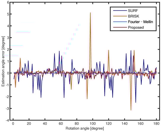
Figure 6.
Rotation estimation errors for all rotation angles of the Lena image with no noise (scale 0.8).
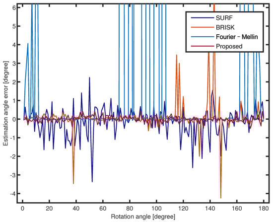
Figure 7.
Rotation estimation errors for all rotation angles of the Lena image with (scale 0.8).
4.3. Scale Estimation Error
Table 3 illustrates the scale estimation errors of the 12 images with a standard deviation and . All scales were estimated from 0.5 to 1 in 0.05 steps, and the results include noise and no-noise errors. The scale estimation errors of different scenes of the proposed method are within a reasonable range. Combined with the analysis of Figure 8 and Figure 9, the proposed scale estimation method demonstrates more stable precision when the input scale is from 0.7 to 1 in both the no-noise image and noise image. As shown in Table 3, Fourier–Mellin achieves a higher scale estimation precision than the other methods. In particular, it is more sensitive to noisy images with a scale of less than 0.7, as shown in Figure 9. It can be obtained that the scale estimation precision of the proposed method is not the highest, whereas it is most robust to noise in the noise comparison experiments.
Table 3.
Comparison of fixed scale estimation errors (the fixed rotation angle is 60 and scale is 0.8).
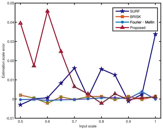
Figure 8.
Scale estimation errors for different input scales of the Lena image with .
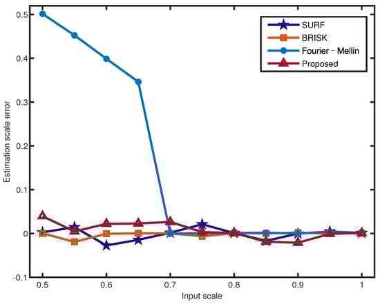
Figure 9.
Scale estimation errors for different input scales of the Lena image with .
The average execution times of the proposed method and other approaches were compared, as shown in Table 4. The proposed method was coded using MATLAB, which was executed on a computer with an i3-10100 CPU @ 3.6 GHz, 16 GB RAM. The execution time of the proposed method is larger than the other compared approaches due to the following reasons: The proposed method was entirely coded using the MATLAB language. Fourier–Mellin was entirely coded using the C++ language, and this method requires multiple Fourier transforms and has high algorithmic complexity. The SURF and BRISK algorithms were partially coded using the C++ language. Despite this execution time drawback, the execution time may be improved by coding using another programming language.
Table 4.
Comparison of the execution times for rotation and scale estimation.
5. Conclusions
In this paper, we proposed a robust and efficient rotation and scale estimation method based on the Gabor filter. The orientation features of the image were extracted by the Gabor filter, which are called Gabor features. Moreover, we proposed a modified PCNN model to measure the similarity between the Gabor features of the image and its rotation. The rotation angle was computed by searching the global minimum of the correlation coefficients. Coarse estimation allowed us to limit the actual rotation angle to a small range. We refined the estimation using a subdivision of the step to obtain a higher precision estimated angle. After obtaining the rotation angle, we can calculate the scale by the matched Gabor features. Compared with other rotation and scale methods, the accuracy of the proposed method was demonstrated. In addition to large rotation angle (>90) estimation, the proposed method could also be robust to noise. For future work, we expect to apply this method to 3D angle estimation.
Author Contributions
Conceptualization, W.T.; methodology, W.T.; software, W.T.; validation, W.T., F.J. and X.W.; formal analysis, W.T.; investigation, W.T.; resources, W.T.; data curation, W.T.; writing—original draft preparation, W.T.; writing—review and editing, W.T.; visualization, W.T.; supervision, F.J. and X.W.; project administration, F.J. and X.W.; funding acquisition, F.J. All authors have read and agreed to the published version of the manuscript.
Funding
This research was funded by the National Natural Science Foundation of China (Grant Number 61201391).
Data Availability Statement
Not applicable.
Conflicts of Interest
The authors declare no conflict of interest.
Abbreviations
The following abbreviations are used in this paper:
| PCNN | Pulse-coupled neural network |
| mPCNN | Modified pulse-coupled neural network |
| POC | Phase-only correlation |
References
- Cao, W. Applying image registration algorithm combined with CNN model to video image stitching. J. Supercomput. 2021, 77, 13879–13896. [Google Scholar] [CrossRef]
- Jose, J.; Gautam, N.; Tiwari, M.; Tiwari, T.; Suresh, A.; Sundararaj, V.; Rejeesh, M. An image quality enhancement scheme employing adolescent identity search algorithm in the NSST domain for multimodal medical image fusion. Biomed. Signal Process. Control 2021, 66, 102480. [Google Scholar] [CrossRef]
- Kumar, S.; Azartash, H.; Biswas, M.; Nguyen, T. Real-time affine global motion estimation using phase correlation and its application for digital image stabilization. IEEE Trans. Image Process. 2011, 20, 3406–3418. [Google Scholar] [CrossRef]
- Oh, C.; Kim, H.; Cho, H. Rotation Estimation and Segmentation for Patterned Image Vision Inspection. Electronics 2021, 10, 3040. [Google Scholar] [CrossRef]
- Paul, S.; Pati, U.C. A comprehensive review on remote sensing image registration. Int. J. Remote Sens. 2021, 42, 5396–5432. [Google Scholar] [CrossRef]
- Ren, Z.; Chen, C.; Fang, M. Self-calibration method of gyroscope and camera in video stabilization. In Proceedings of the 2021 International Conference on Electronic Information Engineering and Computer Science (EIECS), Changchun, China, 23–26 September 2021; IEEE: Piscataway, NJ, USA, 2021; pp. 958–962. [Google Scholar]
- Ren, Z.; Fang, M.; Chen, C.; Kaneko, S.I. Video stabilization algorithm based on virtual sphere model. J. Electron. Imaging 2021, 30, 021002. [Google Scholar] [CrossRef]
- Zhang, Y.; Mei, X.; Ma, Y.; Jiang, X.; Peng, Z.; Huang, J. Hyperspectral Panoramic Image Stitching Using Robust Matching and Adaptive Bundle Adjustment. Remote Sens. 2022, 14, 4038. [Google Scholar] [CrossRef]
- Aguiar, M.J.R.; Alves, T.d.R.; Honório, L.M.; Junior, I.C.; Vidal, V.F. Performance Evaluation of Bundle Adjustment with Population Based Optimization Algorithms Applied to Panoramic Image Stitching. Sensors 2021, 21, 5054. [Google Scholar] [CrossRef] [PubMed]
- Luo, X.; Tan, Z.; Ding, Y. Accurate line reconstruction for point and line-based stereo visual odometry. IEEE Access 2019, 7, 185108–185120. [Google Scholar] [CrossRef]
- Tang, C.; Zhao, X.; Chen, J.; Chen, L.; Zhou, Y. Fast stereo visual odometry based on LK optical flow and ORB-SLAM2. Multimed. Syst. 2020, 1–10. [Google Scholar] [CrossRef]
- Zhan, K.; Teng, J.; Ma, Y. Spiking Cortical Model for Rotation and Scale Invariant Texture Retrieval. J. Inf. Hiding Multim. Signal Process. 2013, 4, 155–165. [Google Scholar]
- Rizzini, D.L. Angular Radon spectrum for rotation estimation. Pattern Recognit. 2018, 84, 182–196. [Google Scholar] [CrossRef]
- Fujisawa, T.; Ikehara, M. High-accuracy image rotation and scale estimation using radon transform and sub-pixel shift estimation. IEEE Access 2019, 7, 22719–22728. [Google Scholar] [CrossRef]
- Bay, H.; Ess, A.; Tuytelaars, T.; Van Gool, L. Speeded-up robust features (SURF). Comput. Vis. Image Underst. 2008, 110, 346–359. [Google Scholar] [CrossRef]
- Leutenegger, S.; Chli, M.; Siegwart, R.Y. BRISK: Binary robust invariant scalable keypoints. In Proceedings of the 2011 International Conference on Computer Vision, Barcelona, Spain, 6–13 November 2011; IEEE: Piscataway, NJ, USA, 2011; pp. 2548–2555. [Google Scholar]
- Wan, Y.; Wei, N. A fast algorithm for recognizing translated, rotated, reflected, and scaled objects from only their projections. IEEE Signal Process. Lett. 2009, 17, 71–74. [Google Scholar] [CrossRef]
- Zhang, X.; Homma, N.; Ichiji, K.; Abe, M.; Sugita, N.; Yoshizawa, M. A faster 1-D phase-only correlation-based method for estimations of translations, rotation and scaling in images. IEICE Trans. Fundam. Electron. Commun. Comput. Sci. 2014, 97, 809–819. [Google Scholar] [CrossRef]
- Faugeras, O.D.; Lustman, F. Motion and structure from motion in a piecewise planar environment. Int. J. Pattern Recognit. Artif. Intell. 1988, 2, 485–508. [Google Scholar] [CrossRef]
- Zhang, Z.; Hanson, A.R. 3D reconstruction based on homography mapping. In Proceedings of the ARPA96; 1996; pp. 1007–1012. Available online: https://www.semanticscholar.org/paper/3-D-Reconstruction-Based-on-Homography-Mapping-Zhangy-Allen/cc16b477fd05d7c52d6d2e0222a962f68debf430 (accessed on 5 October 2022).
- Malis, E.; Vargas, M. Deeper Understanding of the Homography Decomposition for Vision-Based Control. Ph.D. Thesis, INRIA, Antibes, France, 2007. [Google Scholar]
- Pan, B.; Wang, Y.; Tian, L. Automated initial guess in digital image correlation aided by Fourier–Mellin transform. Opt. Eng. 2017, 56, 014103. [Google Scholar] [CrossRef]
- Pan, B.; Tian, L.; Song, X. Real-time, non-contact and targetless measurement of vertical deflection of bridges using off-axis digital image correlation. Ndt E Int. 2016, 79, 73–80. [Google Scholar] [CrossRef]
- Pan, B.; Li, K. A fast digital image correlation method for deformation measurement. Opt. Lasers Eng. 2011, 49, 841–847. [Google Scholar] [CrossRef]
- Yu, K.; Yang, R.; Zeng, H.; Peng, A. Joint estimation of image rotation angle and scaling factor. In Proceedings of the 2021 Asia-Pacific Signal and Information Processing Association Annual Summit and Conference (APSIPA ASC), Tokyo, Japan, 14–17 December 2021; IEEE: Piscataway, NJ, USA, 2021; pp. 1716–1721. [Google Scholar]
- Chen, C.; Ni, J.; Shen, Z. Effective estimation of image rotation angle using spectral method. IEEE Signal Process. Lett. 2014, 21, 890–894. [Google Scholar]
- Shen, L.; Bai, L.; Fairhurst, M. Gabor wavelets and general discriminant analysis for face identification and verification. Image Vis. Comput. 2007, 25, 553–563. [Google Scholar] [CrossRef]
- Kang, X.; Li, C.; Li, S.; Lin, H. Classification of hyperspectral images by Gabor filtering based deep network. IEEE J. Sel. Top. Appl. Earth Obs. Remote Sens. 2017, 11, 1166–1178. [Google Scholar] [CrossRef]
- Chen, Q.S.; Defrise, M.; Deconinck, F. Symmetric phase-only matched filtering of Fourier–Mellin transforms for image registration and recognition. IEEE Trans. Pattern Anal. Mach. Intell. 1994, 16, 1156–1168. [Google Scholar] [CrossRef]
- Giarra, M.N.; Charonko, J.J.; Vlachos, P.P. Measurement of fluid rotation, dilation, and displacement in particle image velocimetry using a Fourier–Mellin cross-correlation. Meas. Sci. Technol. 2015, 26, 035301. [Google Scholar] [CrossRef]
- Xu, Q.; Long, X.; Kuang, H.; Schwertfeger, S. Rotation Estimation for Omni-directional Cameras Using Sinusoid Fitting. J. Intell. Robot. Syst. 2021, 103, 10. [Google Scholar] [CrossRef]
- Rizzini, D.L.; Fontana, E. Rotation Estimation Based on Anisotropic Angular Radon Spectrum. IEEE Robot. Autom. Lett. 2022, 7, 7279–7286. [Google Scholar] [CrossRef]
- Ryu, B.H.; Lee, I.H.; Kang, B.S.; Kim, K.T. Frame Selection Method for ISAR Imaging of 3-D Rotating Target Based on Time-Frequency Analysis and Radon Transform. IEEE Sens. J. 2022, 22, 19953–19964. [Google Scholar] [CrossRef]
- Self-supervised optical flow derotation network for rotation estimation of a spherical camera. Adv. Robot. 2021, 35, 118–128. [CrossRef]
- Zhang, J.Y.; Ramanan, D.; Tulsiani, S. RelPose: Predicting Probabilistic Relative Rotation for Single Objects in the Wild. arXiv 2022, arXiv:2208.05963. [Google Scholar]
- Gao, G.; Lauri, M.; Wang, Y.; Hu, X.; Zhang, J.; Frintrop, S. 6D object pose regression via supervised learning on point clouds. In Proceedings of the 2020 IEEE International Conference on Robotics and Automation (ICRA), Paris, France, 31 May–31 August 2020; IEEE: Piscataway, NJ, USA, 2020; pp. 3643–3649. [Google Scholar]
- Chen, W.; Jia, X.; Chang, H.J.; Duan, J.; Shen, L.; Leonardis, A. Fs-net: Fast shape-based network for category-level 6d object pose estimation with decoupled rotation mechanism. In Proceedings of the IEEE/CVF Conference on Computer Vision and Pattern Recognition, Virtual, 19–25 June 2021; pp. 1581–1590. [Google Scholar]
- Bukschat, Y.; Vetter, M. EfficientPose: An efficient, accurate and scalable end-to-end 6D multi object pose estimation approach. arXiv 2020, arXiv:2011.04307. [Google Scholar]
- Johnson, J.L.; Ritter, D. Observation of periodic waves in a pulse-coupled neural network. Opt. Lett. 1993, 18, 1253–1255. [Google Scholar] [CrossRef] [PubMed]
- Kinser, J.M.; Johnson, J.L. Stabilized input with a feedback pulse-coupled neural network. Opt. Eng. 1996, 35, 2158–2161. [Google Scholar] [CrossRef]
- Wang, Z.; Wang, S.; Zhu, Y.; Ma, Y. Review of image fusion based on pulse-coupled neural network. Arch. Comput. Methods Eng. 2016, 23, 659–671. [Google Scholar] [CrossRef]
- Johnson, J.L.; Taylor, J.R.; Anderson, M. Pulse-coupled neural network shadow compensation. In Proceedings of the Applications and Science of Computational Intelligence II, Orlando, FL, USA, 18–22 July 1999; SPIE: Cergy-Pontoise, France, 1999; Volume 3722, pp. 452–456. [Google Scholar]
- Mehrtash, N.; Jung, D.; Klar, H. Image preprocessing with dynamic synapses. Neural Comput. Appl. 2003, 12, 33–41. [Google Scholar] [CrossRef]
- Wang, W.; Zhou, W.; Zhao, X. Airplane extraction and identification by improved PCNN with wavelet transform and modified Zernike moments. Imaging Sci. J. 2014, 62, 27–34. [Google Scholar] [CrossRef]
- Mohammed, M.M.; Badr, A.; Abdelhalim, M.B. Image classification and retrieval using optimized pulse-coupled neural network. Expert Syst. Appl. 2015, 42, 4927–4936. [Google Scholar] [CrossRef]
- Zhan, K.; Shi, J.; Wang, H.; Xie, Y.; Li, Q. Computational mechanisms of pulse-coupled neural networks: A comprehensive review. Arch. Comput. Methods Eng. 2017, 24, 573–588. [Google Scholar] [CrossRef]
- Grigorescu, S.E.; Petkov, N.; Kruizinga, P. Comparison of texture features based on Gabor filters. IEEE Trans. Image Process. 2002, 11, 1160–1167. [Google Scholar] [CrossRef]
- Rajadell, O.; Garcia-Sevilla, P.; Pla, F. Spectral–spatial pixel characterization using Gabor filters for hyperspectral image classification. IEEE Geosci. Remote Sens. Lett. 2012, 10, 860–864. [Google Scholar] [CrossRef]
- Wang, L.; Bi, S.; Li, H.; Gu, Y.; Zhai, C. Fast initial value estimation in digital image correlation for large rotation measurement. Opt. Lasers Eng. 2020, 127, 105838. [Google Scholar] [CrossRef]
- ImageProcessingPlace. n.d. Available online: https://www.imageprocessingplace.com/ (accessed on 2 October 2022).


Publisher’s Note: MDPI stays neutral with regard to jurisdictional claims in published maps and institutional affiliations. |
© 2022 by the authors. Licensee MDPI, Basel, Switzerland. This article is an open access article distributed under the terms and conditions of the Creative Commons Attribution (CC BY) license (https://creativecommons.org/licenses/by/4.0/).