Abstract
In order to mitigate the influence of negative impedance characteristics on the stability of a DC microgrid with a constant power load, and the influence of nonlinear characteristics of a bidirectional converter on DC bus voltage, a control method of a bidirectional converter based on a multivariable-feedback sliding-mode control is proposed. The traditional control method usually uses the DC bus voltage error as a single controlled variable to optimize the design of the control law, which will lead to the lack of global coordination of each state variable. In this paper, the multi-state process variables-feedback sliding-mode control of a bidirectional DC/DC converter is designed, which can effectively improve the stability of the DC bus voltage, despite dynamic power disturbances. Firstly, the model of a bidirectional DC/DC converter, as well as the state equations of a converter with constant power load and resistive load, are analyzed. Secondly, to express various dynamic characteristics of the DC bus voltage fluctuation process, the output voltage error, the inductor current error and its integral are defined as the controlled state variables. Then, the multivariable weight combination-based sliding-mode surface is defined, and the sliding-mode controller is derived from a fast exponential power reaching law. Thirdly, the existence and stability of the multivariable-feedback sliding-mode control and the choice of control law parameters are discussed. Finally, MATLAB / Simulink software is used to simulate the proposed controller. Compared with PI and intelligent PID controllers, the proposed controller has the fastest response speed, the smallest steady-state voltage deviation and the best adjustment performance.
1. Introduction
In recent years, the DC microgrid system has had the advantages of less conversion times, a simple control structure, no need for reactive power compensation, and no need for phase and frequency control, which has attracted more and more attention. The basic control goal of a DC microgrid is to ensure that the DC bus voltage fluctuates within the allowable range, as well as to provide a reliable power supply for the DC loads. In a DC microgrid, energy storage devices are usually used to smooth the power fluctuations of micro-sources and loads, balance the power distribution of the DC microgrid, and improve the reliability of the power supply [1,2,3]. Energy storage devices (such as batteries, super capacitors, etc.) are connected in parallel to the DC bus through a bidirectional DC/DC converter.
The bidirectional DC/DC converter is a very important device in the DC microgrid for power regulation and DC bus voltage stabilization [4]. Reference [5] proposed a new isolated zero-voltage switching/zero-current switching push–pull DC/DC converter. This converter provides an attractive solution for a distributed DC power system, uninterruptible DC power system, or battery charge/discharge system. Reference [6] proposed a bidirectional DC/DC converter for battery-powered devices that maintains a stabilized output voltage at an input voltage lower than, higher than, or equal to the output voltage and maximizes battery utilization with the minimum size of external components. Reference [7] proposed a two-input transformerless DC/DC converter. This converter has a large voltage conversion ratio with low-voltage and current stress on semiconductors and low input current ripple. It can transfer DC power as a two-phase converter with three and four input voltage sources to increase the availability of the multiple-input voltage-levels power supply.
Bidirectional DC/DC converters enable the direct connection of multiple power sources and loads to a DC microgrid. Under the condition of rated DC bus voltage, the stable load can be regarded as a constant power load equivalent. The negative impedance characteristics of the constant power load may cause the system to be unstable [8,9]. Reference [10] discussed the influence of a constant power load on the stability of a DC microgrid, and designed an RST digital feedback controller based on pole placement and sensitivity function shaping techniques. The controller is used to compensate for the oscillation effect of the constant power load and realize the voltage stability on the DC microgrid bus. Reference [11] proposed a new robust parameter control technology for the system instability phenomenon caused by the negative impedance characteristic when a constant power load is applied to the DC bus. A fixed-order robust controller is designed, based on the linear programming of Chebyshev’s theorem, which can be used to improve the overall performance of the system. However, the control law parameters of these linear methods are often optimized around a certain approximate steady-state equilibrium point. When the constant power load changes abruptly, the applicability of the control law will be reduced, and the DC bus voltage cannot be adjusted very quickly or smoothly. Therefore, the research on the nonlinear control of the bidirectional DC/DC converter with dynamic constant power load of a DC microgrid is of great significance, to maintain the stability of the DC microgrid.
As it has both battery charging and discharging functions, the bidirectional DC/DC converter can flexibly connect the battery energy storage unit to the DC microgrid to achieve the advantage of effective distributed power source utilization. However, the bidirectional DC/DC converter is essentially a nonlinear discrete system, and the parameters of the system model have the characteristics of uncertainty and time-variance. When the loads or input voltage change suddenly, the DC output voltage will appear as a large drop, large-scale oscillation, with a long adjustment time, large steady-state static error, and so on [12]. Furthermore, if the input voltage or load of the system changes in a large range, the PWM duty cycle of the converter will change greatly, which makes the bidirectional DC/DC converter show serious nonlinear characteristics. In addition, due to the change of system topology caused by bidirectional power flow, the converter system has the characteristics of a dynamic variable structure. These unfavorable characteristics require the DC microgrid bidirectional DC/DC converter to have a more advanced controller to obtain a good DC bus voltage control effect.
Over the past decade, observer-based methods have been widely used because they can improve system control performance and reduce state feedback sampling errors. Reference [13] proposed a hybrid fuzzy PI-based control scheme for a multiple input converter (MIC) topology. The proposed hybrid fuzzy PI controller includes a conventional PI controller at steady state and fuzzy PI at transient state. which helps in tracking a predefined speed profile to have complete realization of the DC/DC converter. Reference [14] proposed an effective sensor fault detection and system reconfiguration approach for the DC/DC boost converter. By designing a Luenberger observer to solve the problem of a sensor fault detection of the DC/DC boost converter, the Luenberger can obtain the fluctuation of the output voltage and current caused by the system load change in time, so as to realize the effective control of the DC/DC converter. However, when faced with a large-scale continuous sudden change of loads, the observer control method has a long adjustment transition time. Therefore, this paper proposed a bidirectional DC/DC converter control method for the DC microgrid based on a sliding-mode control (SMC), which is used to improve the response speed of the system and solve the system instability problem of a DC microgrid with a constant power load.
Sliding-mode control is a nonlinear control method with strong robustness, which is fully applicable to DC/DC converters, and is increasingly used in the field of power electronics. The working characteristic of the sliding-mode controller is high frequency switching, which will inevitably lead to large power loss and chattering problems [15]. In recent years, a large number of scholars have devoted themselves to the research in this area, and proposed many improved control methods, such as hysteresis control, equivalent control, fixed-frequency PWM control and so on [16,17,18]. Reference [19] proposed a new fixed-frequency double-integral sliding-mode control method, which can realize the regulation of a DC microgrid bus voltage under unknown load demand and model uncertainty. Compared with traditional linear controllers, it has better robustness. Reference [20] proposed a state observer-based sliding-mode controller for a DC/DC boost converter. When the input voltage and load resistance change, the state observer is used to estimate the input voltage and load resistance value in real time, and the estimated value is fed back to the controller. The adaptive sliding-mode surface is designed by using the estimated value, and the control law is obtained by combining the exponential reaching law, so that the output voltage of the converter can track the reference voltage. Reference [21] proposed a combination of precise feedback linearization and backstep sliding-mode control for the bidirectional DC/DC converter of a DC microgrid energy storage unit, which ensures the robustness and stability of the system under external disturbances, to a certain extent. In order to improve the convergence speed of sliding-mode control and suppress chattering, reference [22] proposed an adaptive sliding-mode control method with an enhanced optimal reaching law. On the basis of traditional hysteretic sliding-mode control, the particle swarm algorithm is used to improve the exponential reaching law, which has a good current tracking effect. Reference [23] proposed a new sliding-mode observer based on an optimized constant-velocity reaching law. By introducing an exponential term based on the constant-velocity reaching law, it can not only shorten the sliding-mode arrival time, but also effectively suppress chattering. Reference [24] proposes a supervisory high-order sliding-mode control (FSHSMC) technique for the energy management of hybrid energy sources connected to a smart grid via a DC-link voltage. Due to the exceptionally low number of fixed gains, the FSHSMC technique is less sensitive to uncertainties, as well as greatly increasing the system’s global stability and robustness feature.
For the DC microgrid bus voltage stability control objective, typical sliding-mode control or nonlinear control methods, the DC bus voltage error is often used as a single controlled variable to optimize the design of the control law. These methods lack the global coordination of various state variables, and are not able to easily control the complex nonlinear regulation process of DC/DC converters. Therefore, these controllers need to be further improved to coordinate various process variables in the regulation process of the DC/DC converter, so as to achieve the control effect of enhancing the robustness and stability of the DC bus voltage. For this reason, this paper takes advantage of the strong designability of sliding-mode control and adopts the multi-state process variables of the bidirectional DC/DC converter as controlled input variables, such as the output voltage error, the inductor current error and its integral, to design the control law. This method has the characteristics of multi-state coordination, fast response, high robustness and high stability accuracy in the adjustment process, and can effectively improve the distributed power-based bidirectional DC/DC converter’s high stability access capability.
The research purpose of this paper is to propose a multivariable-feedback sliding-mode control-based strong robust DC bus voltage control method for a bidirectional DC/DC converter, to mitigate the influence of negative impedance characteristics on system stability, as well as complex nonlinear characteristics of a DC microgrid with a constant power load. A fast power reaching law is introduced into the controller to improve the response speed of the traditional sliding-mode control and suppress chattering. Firstly, the state equation of the bidirectional DC/DC converter with constant power load and resistive load is analyzed. Using the output voltage error, the inductor current error and its integral are defined as controlled state variables to design the multivariable-feedback sliding-mode controller. Then, the stability and existence of the sliding-mode control system and the selection range of the control law parameters are discussed. Finally, through MATLAB/Simulink digital simulation and hardware experiments, it is verified that the proposed multivariable-feedback sliding-mode controller has faster response speed and smaller voltage error than the traditional PI controller and intelligent PID (IPID) controller.
In summary, the main contributions of this paper include: (1) To mitigate the influence of negative impedance characteristics on the stability of a DC microgrid with a constant power load and the influence of nonlinear characteristics of a bidirectional converter on DC bus voltage, a multivariable-feedback sliding-mode control is designed. (2) The state equation of a bidirectional DC/DC converter with a constant power load and resistive load is analyzed, and the output voltage error, inductor current error and its integral are defined as state variables to design a multivariable-feedback sliding-mode surface. (3) The fast power reaching rate is introduced into the sliding-mode controller to improve the adjust response speed and suppress chattering. The existence and stability of a sliding-mode control law, as well as the selection principle of sliding-mode surface coefficients are discussed. (4) The feasibility and effectiveness of the proposed multivariable-feedback sliding-mode control method are verified by multi-scenario digital simulation and hardware experiments.
This paper is organized as follows: In Section 2, the structure of the DC microgrid is presented. Section 3 analyzes the negative impedance characteristics of a constant power load. In Section 4, the multivariable-feedback sliding-mode controller of a bidirectional DC/DC converter is designed. Section 5 gives the MATLAB/Simulink digital simulation results and analysis, and compares this with the traditional PI and IPID controller proposed in the previous literature. Section 6 verifies the proposed multivariable-feedback sliding-mode control method through hardware experiments. Finally, Section 7 draws conclusions.
2. DC Microgrid Structure
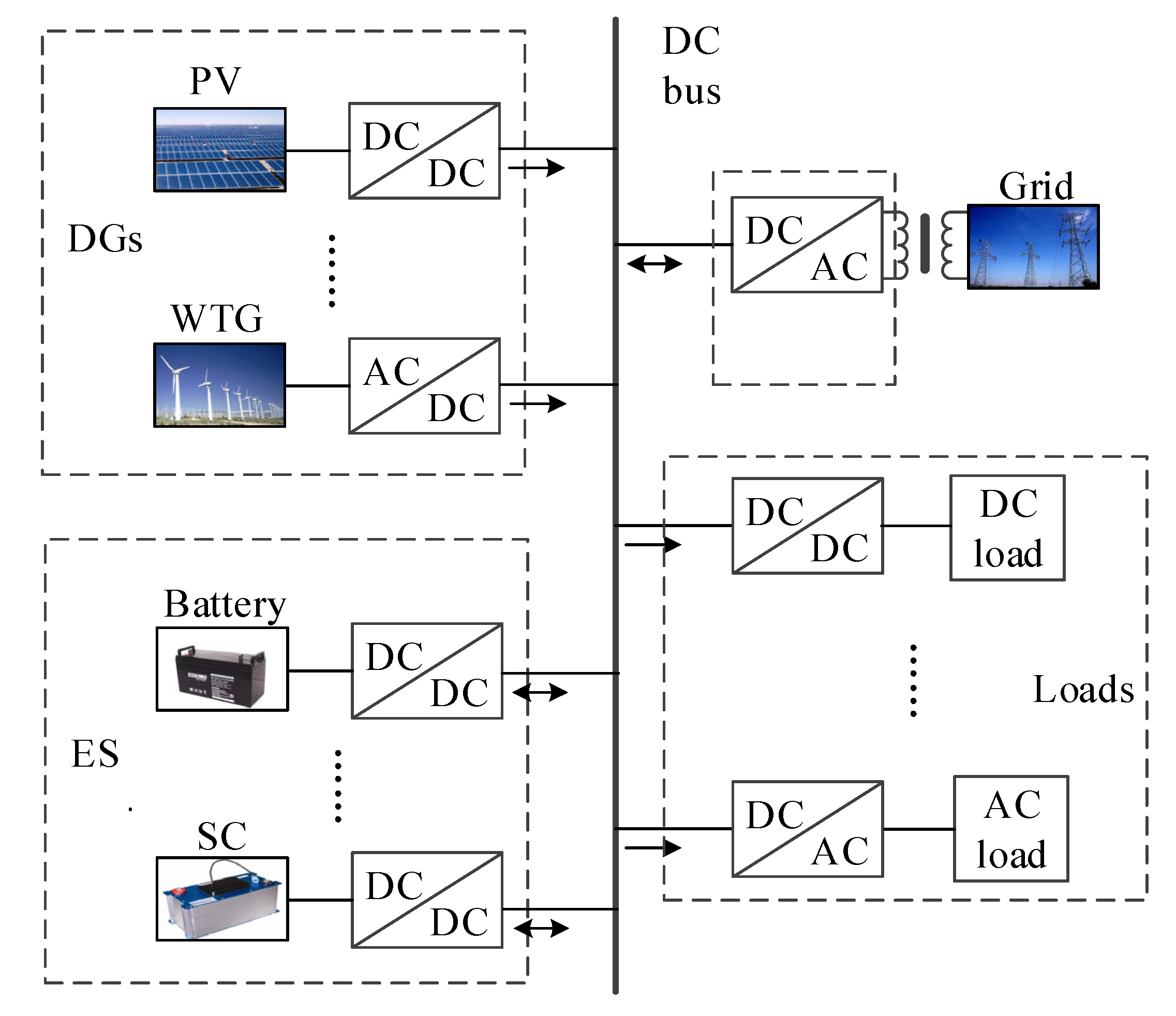
Figure 1 is a typical structure diagram of a DC microgrid. Distributed power sources, energy storage devices, loads, etc., are connected in parallel on the DC bus, and the DC network can be connected to the external AC grid through a grid-connected converter. The power supply is usually composed of renewable energy such as solar energy, wind energy, biomass energy, etc., and is connected to the busbar through the converter; energy storage devices generally use batteries or super capacitors, which can store energy when connected to the grid, and operate as a power source during island operation, which can maintain the power balance of the DC microgrid; the grid-connected converter can effectively isolate AC grid disturbance; the load types include DC load and AC load.
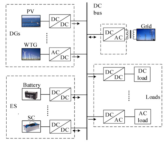
Figure 1.
Typical structure diagram of DC microgrid system.
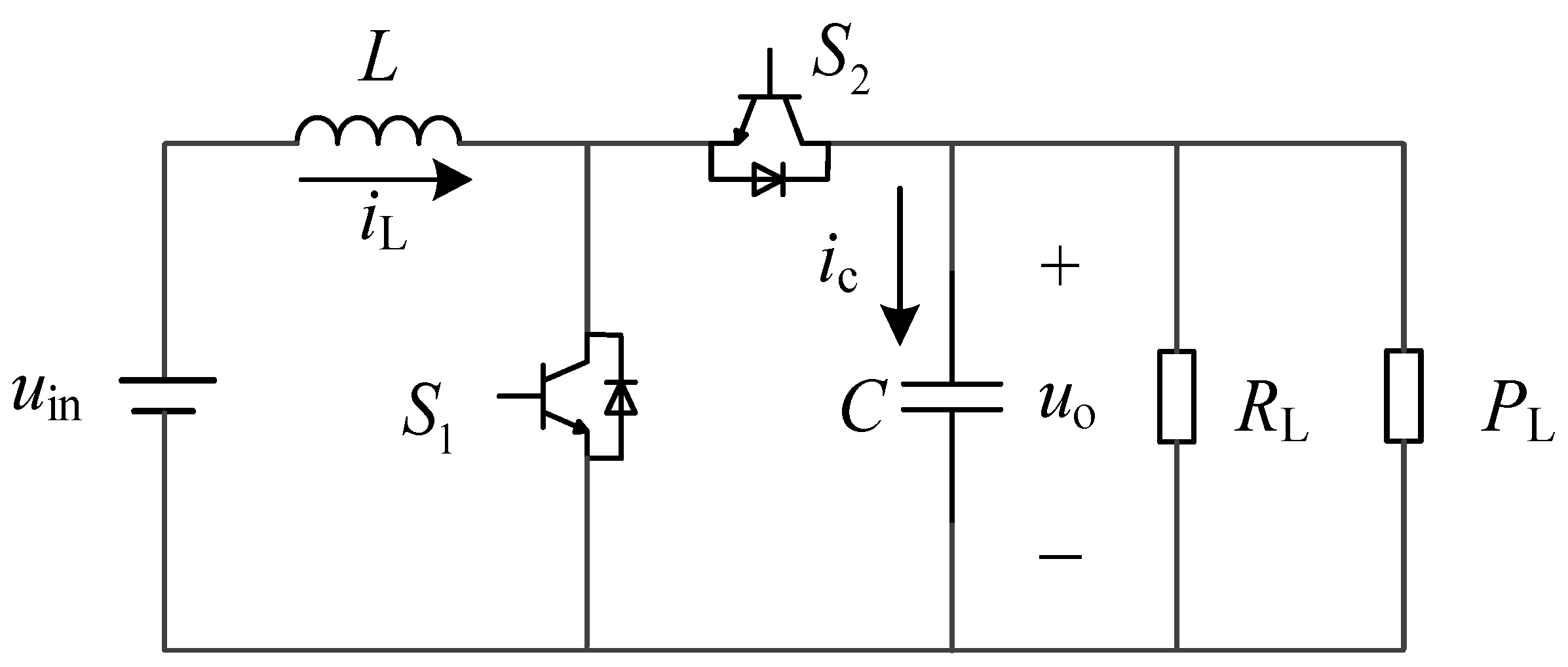
In this paper, the DC microgrid model selects the battery energy storage unit as the main power supply, and the bus interface converter adopts a bidirectional DC–DC converter, as shown in Figure 2. This kind of converter is the most popular structure for low power applications at present. It has the characteristics of a simple structure, convenient control and high efficiency. When the power output by the distributed power source is excessive, the battery absorbs and stores it through the bidirectional DC–DC converter. When the power of the grid is insufficient, the battery energy storage unit discharges to maintain the power balance of the DC microgrid.
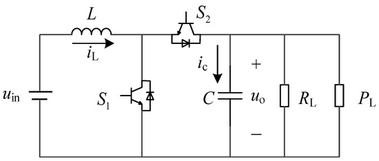
Figure 2.
Model of bidirectional DC/DC converter.
In the Figure 2, uin is the output voltage of the battery, iL is the inductor current, and iC is the capacitor current on the high-voltage side of the converter. uo is the converter output voltage, RL is the resistive load, and PL is the constant power load in the DC microgrid.
The bidirectional DC/DC converter adopts the complementary PWM control method. When S1 is turned on, S2 is turned off, and when S2 is turned on, S1 is turned off, and the two switches operate at the same time. Compared with the independent PWM control method, the complementary PWM method does not require the logic unit to perform transition switching between the BUCK and BOOST circuits, which improves the work efficiency and the system responds faster. From reference [10], the state-space averaging model of the circuit is as follows
where, u is the duty cycle of switch S2.
3. Negative Impedance Characteristic of Constant Power Load Analysis
The load in the DC microgrid is directly connected to the DC bus through the DC/DC converter, and the absorbed power is a constant value, which can be regarded as a constant power load, equivalently. Figure 3 is a characteristic diagram of a constant power load. It can be seen that when the load power is constant, the current decreases with the increase of the voltage, which is a nonlinear characteristic.
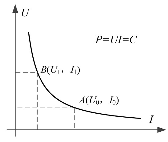
Figure 3.
Constant power load characteristic curve.
Assuming the power of constant power load is PL, and the voltage and current at the stable operating point A are U0 and I0, respectively, then
where, C represents constant power.
Taking a small signal perturbation at point A, it has
Then
The small-signal equivalent impedance of the constant power load is obtained as
It can be seen that the constant power load has a negative impedance characteristic.
Taking the bidirectional DC/DC converter working in BUCK mode as an example, a small signal disturbance is applied to Equation (1), assuming
where, , Uin, , Uo, , IL, and U are the disturbance amount and average value of input voltage, the disturbance amount and average value of output voltage, the disturbance amount and average value of inductor current, the disturbance amount and average value of duty cycle, respectively.
Combining Equations (1) and (6), it has
Taking Laplace transform of Equation (7), it obtains input and output transfer function as
According to the characteristic equation of transfer function, the poles are obtained as
According to the Rouse criterion, if the system is stable, the root of the characteristic equation must be in the left half-plane, which satisfies
Therefore, the constant power load must satisfy the above formula to ensure the stability of the DC microgrid.
4. Bidirectional DC/DC Converter Sliding-Mode Controller Design
4.1. Selection of Sliding-Mode Function
To express various dynamic characteristics of the DC bus voltage fluctuation process, this paper defines the output voltage error, the inductor current error and its integral as the controlled state variables
where, Uoref is the output voltage reference value, iref is the inductor current reference value, and iref =kx1 = k(Uoref − βuo). β is the output voltage sampling network ratio, the port voltage of the sampling network is βuo. uo is the output voltage of the converter, and the output voltage sampling is realized by the resistor divider. Introducing the integral term x3 of the current error into the sliding-mode controller as an additional control state variable can reduce the steady-state error caused by finite or fixed switch frequency.
The sliding-mode surface is designed as follows
where, α1, α2, α3 are the sliding-mode coefficients, respectively, and are positive numbers. These coefficients α1, α2, and α3 are selected by using a closed-loop system characteristic equation of state analysis approach. Using the pole placement criterion, it is possible to find approximate ranges for these coefficients α1, α2, and α3. In addition, these coefficients need to be optimized to ensure the existence and stability of the sliding-mode control.
4.2. System Dynamic Equation and Equivalent Control
Differentiating both sides of Equation (11), and substituting the state equation of the bidirectional DC/DC converter under CCM in Equation (1), as well as considering the equation of , the dynamic model of the system is obtained as
Substituting Equation (13) into the sliding surface, it has
Letting , the equivalent control law ueq is obtained as
where, K1 = (k + α1/α2)βL/C, K2 = kLα3/α2, K3 = Lα3/α2.
In addition, by Equation (13), it also has
The equivalent control law can ensure that the system has good steady-state characteristics on the sliding-mode surface, but cannot guarantee the dynamic response characteristics. Therefore, on the basis of the traditional sliding-mode control method, the reaching law is introduced to regulate the movement trajectory of the system, accelerate the convergence speed, and suppress the inherent chattering of the system. The reaching law selects the fast power reaching law introduced in reference [23]
where, m1 > 0, m2 > 0, 0< m3 < 1. This reaching law combines the exponential reaching term and the power reaching term, which has the advantages of small voltage overshoot, high steady-state voltage accuracy, low ripple and chattering, and can also improve the transient performance and anti-disturbance ability of the system.
Combining Equations (14) and (17), the actual sliding-mode control law can be obtained as
where, K4 = m1L/α2, K5 = m2L/α2.
The sliding-mode controller designed in this paper is realized by the fixed frequency PWM method, which uses the control signal to compare with the fixed frequency ramp signal to generate the switch gate pulse signal. The PWM signal can be expressed as
where, vc is the control signal, and vramp is the fixed frequency ramp signal.
In order to simplify the control signal, let vramp = Kuo, combined with Equations (18) and (19), the control signal vc can be obtained as
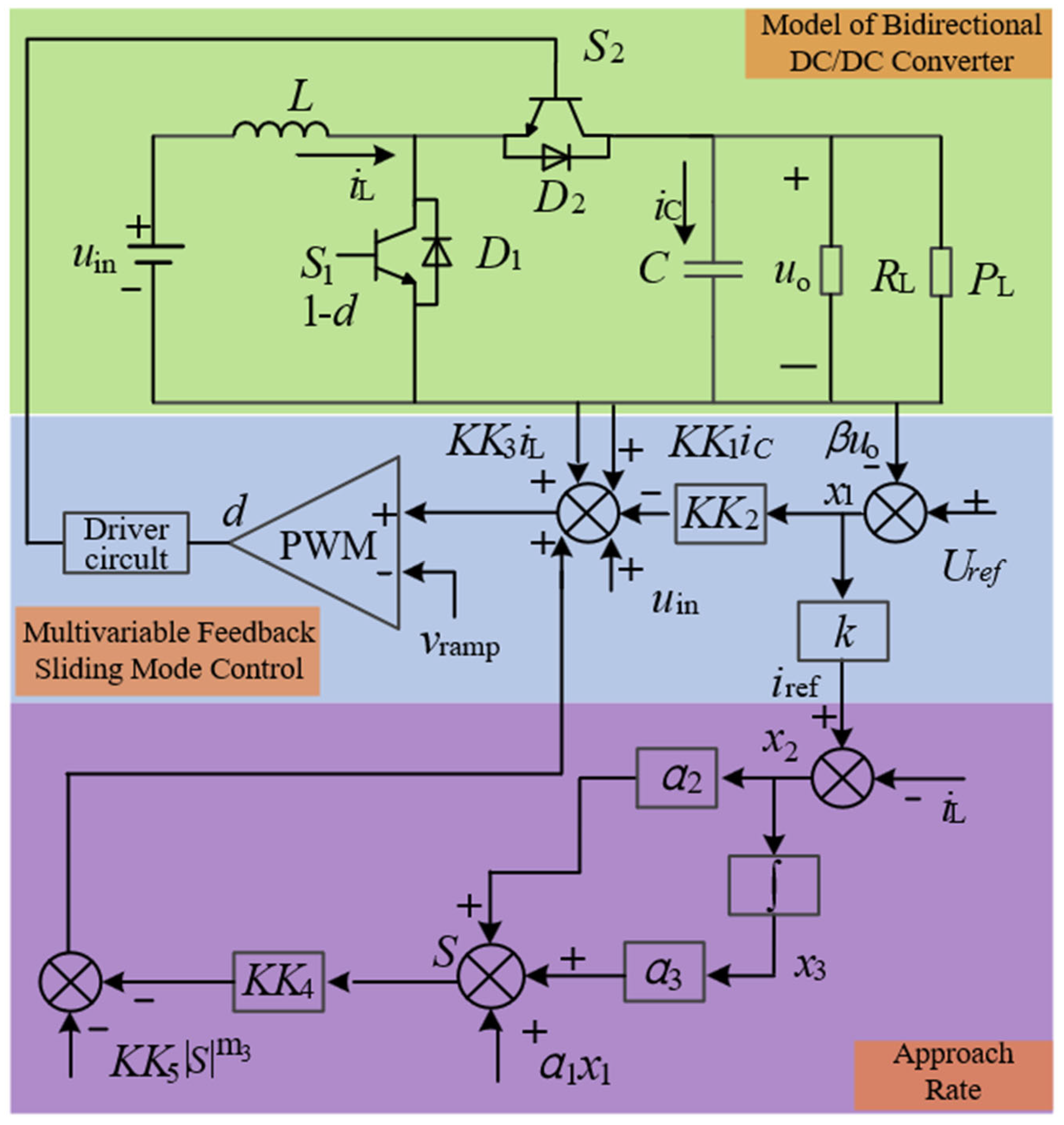
The multivariable-feedback sliding-mode control of the bidirectional DC/DC converter in a DC microgrid principal diagram is shown in Figure 4.
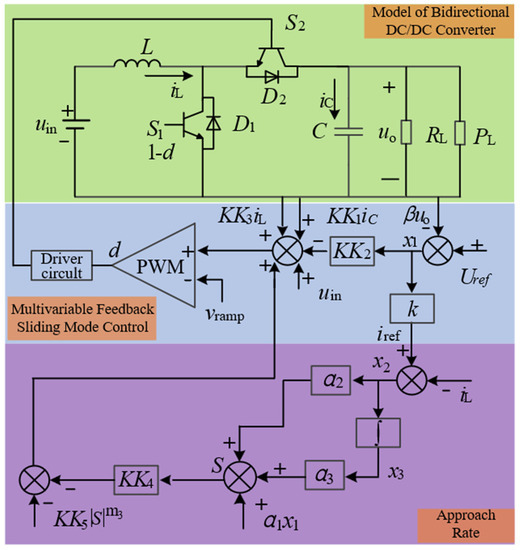
Figure 4.
Multivariable-feedback sliding-mode control of bidirectional DC/DC converter.
4.3. Existence Conditions of Sliding-Mode Control
In order to ensure the existence of the sliding-mode surface, and make the output voltage and current reach the reference value under steady-state conditions, controllability and accessibility must be satisfied under steady-state conditions. Since the fast power reaching law designed in this paper satisfies the stability condition, this part only needs to prove the equivalent control law ueq in Equation (15).
4.3.1. Transversal Condition
Controllability reflects whether the input can control the change of the system state. The transversal condition ensures that the control variable exists in the derivative of the sliding-mode surface, so that when the system input changes dynamically, the sliding-mode controller can control the system state to change with the system input. The transversal condition must be satisfied for the system dynamics to be affected by the sliding-mode controller. The transversal condition of the sliding-mode surface designed in this paper is expressed as:
Substituting Equation (14) into (21), it has
Since α2, L and uo are not zero, the transverse condition is satisfied.
4.3.2. Reachability Analysis
Reachability reflects the ability of the system to reach the sliding surface, and ensures that the system always points to the sliding manifold. Define the switch function as follows
Then the reaching condition is expressed as
From Equations (1), (12), (14) and (23), if Equation (24) holds, it needs to satisfy as
In order to guarantee the existence of sliding-mode motion, a steady-state sliding-mode surface is designed for the sliding-mode controller.
Substituting K1, K2 and K3 into Equation (25), the equation can be simplified as
Therefore, the choice of sliding-mode control parameters must satisfy the inequalities of Equation (26).
4.4. Stability Conditions of Sliding-Mode Control
Since the sliding-mode controller contains state variables of current and voltage, it is difficult to solve by analytical method. In this paper, the method in reference [22] is adopted, which is to derive the ideal sliding dynamics equation of the system first, then analyze the equilibrium point of the system, and finally obtain the stability condition of the system.
4.4.1. Ideal Sliding-Mode
Using the equivalent control variable ueq to replace the duty cycle u of the original bidirectional DC/DC converter, the discontinuous system can be converted into an ideal sliding-mode continuous system.
Substituting Equation (16) into (1), it has
4.4.2. Analysis of Equilibrium Point
Assuming that there is a stable equilibrium point on the sliding surface, the ideal sliding-mode is finally stabilized on the sliding surface. At this equilibrium point, if there is no input or load disturbance, the modal of the system will not change at all, i.e., diL/ dt = duo/dt = 0. Then, the bidirectional DC/DC converter system has
where, IL, Uo, Uin and RL are the inductance current, output voltage, battery input voltage and load resistance under steady-state, respectively.
4.4.3. Linearization of Ideal Sliding-Mode
Suppose the system is in static equilibrium, with Uin = uin, Uoref =uo, iref = IL. Linearizing the ideal sliding-mode surface around its equilibrium point, and assuming IL ≫ and Uo ≫ , it has
where,
The characteristic equation of the linearized system can be expressed as
If the system is stable, it needs to satisfy
When , K1 and K3 are greater than 0, it meets
When , it meets
Existence conditions Equation (26), as well as stability conditions Equations (33) and (34), are the theoretical basis for the parameter selection of the sliding-mode controller. The satisfaction of these conditions ensures the closed-loop stability of the system.
5. Simulation Analysis
In order to verify the effectiveness of the proposed multivariable-feedback sliding-mode control method, MATLAB/Simulink platform was used to carry out a multi-case simulation, and the experimental comparison with the traditional PI control method [13] and the intelligent PID control method [18] was carried out. In the simulation, the DC microgrid circuit diagram is shown in Figure 2, and the circuit parameters are shown in Table 1.

Table 1.
DC microgrid circuit parameters.
The selection of resistive load and constant power load follows Equation (10). Substitute the DC microgrid circuit parameters into Equations (25), (33) and (34) to obtain the sliding-mode control parameter value range that satisfies the existence and closed-loop stability of the sliding-mode controller. Combined with Equations (15), (17) and (18) and through debugging, the multivariable-feedback sliding-mode control parameters are finally obtained as follows: K1 = 270, K2 = 250, K3 = 100, K4 = 100, K5 = 100 and M3 = 0.15.
Linear PID control is a standard control method for DC/DC converters. It combines the proportional, integral and differential of the bus voltage error to calculate the control signal. It finally generates the switch gate pulse control signal to achieve the bus voltage closed-loop regulation. The function of proportional operation is to respond to the error signal of the DC/DC converter control system proportionally in time, to generate the control effect at the fastest speed and reduce the error. The function of integral operation ensures that the steady-state tracking of the controlled variable has no static error. The function of the derivative operation is to enhance the stability and dynamic characteristics of the bus voltage closed-loop control process, including reducing overshoot, shortening adjustment time, speeding up dynamic response, and improving bus voltage accuracy.
The classical experimental optimization method is used to determine the PI control law parameters to ensure the good response characteristics of the closed-loop system. As a comparison, the parameters of the outer voltage loop of PI controller are Kpu = 0.8, Kiu = 100, and the inner current loop parameters are Kpi = 100 and Kii = 10.
However, the DC/DC converter of the DC microgrid belongs to a highly nonlinear system. The PID control law with fixed parameters is not easy to realize the global optimization of the regulation process when the bus voltage error changes in a wide range. During the bus voltage closed-loop regulation process, either the bus voltage overshoot is too large or the regulation time is too long, so it is difficult to find appropriate proportional, integral and differential parameters. Therefore, this paper uses an intelligent piecewise PID control method (IPID) to improve linear PID control characteristics. The IPID control law does not adopt fixed control parameters during the whole closed-loop regulation process, but takes the control parameters as variables. When the bus voltage error is large, the proportional and integral operations are appropriately enhanced to make the PID control output overgrow in a short time. When the bus voltage error is small, the proportional and integral operations will be weakened appropriately to decelerate PID control output. When the bus voltage error is minimal, the proportional and integral operations are further reduced to further slow the PID control output acceleration. The regulation process accelerates the response speed when the error is large, and avoids the overshoot when the error is small, so that the regulation performance of the whole system is greatly improved.
As a comparison, the IPID control method takes the initial value of the inductor current IL and the inductor current error x2 as input. The intelligent decision-making device compares the real-time error x2 feedback with the preset threshold γ. When the real-time error exceeds the preset threshold, PD control is adopted, which avoids overshot and ensures the system has a fast response. When the real-time error is less than the preset threshold, PID control is used to ensure the accuracy of the control. The IPID control method realizes the switching control of two groups of optimized PID parameters. The preset threshold γ = 0.1 IL, when |x2| > γ, Kp = 8.74, Ki = 0, Kd = 0.43; when |x2| ≤ γ, Kp = 4.57, Ki = 0.15, Kd = 0.86.
The energy storage part of this paper uses a lead-acid battery with a rated voltage of 100 V and a battery capacity of 96 Ah.
5.1. Scenario I: Load Variation Simulation
Scenario I is to verify the stability of the system under load dynamic switching. The initial resistive load in the DC microgrid is 250 Ω, and the initial constant power load is 100 W.
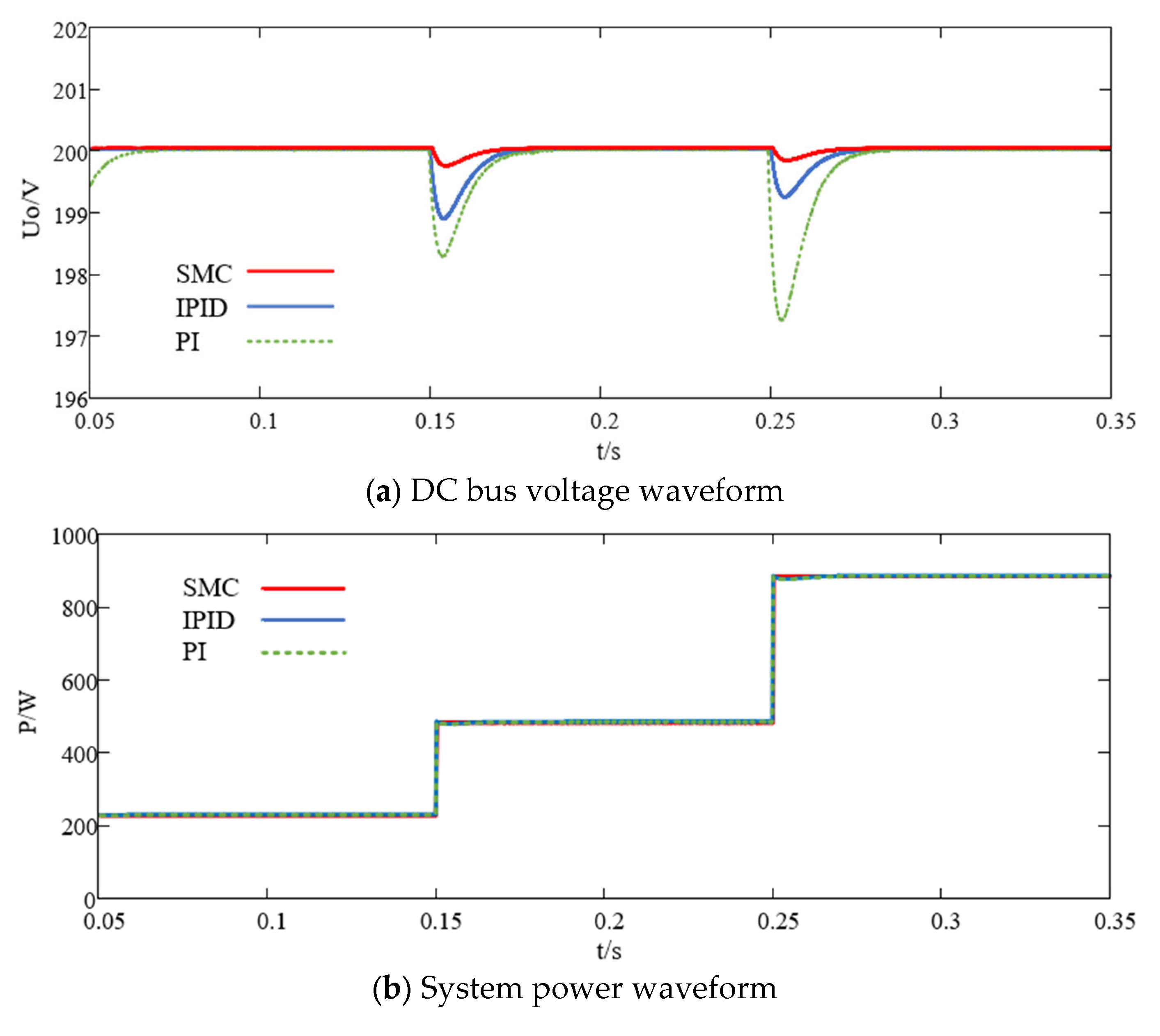
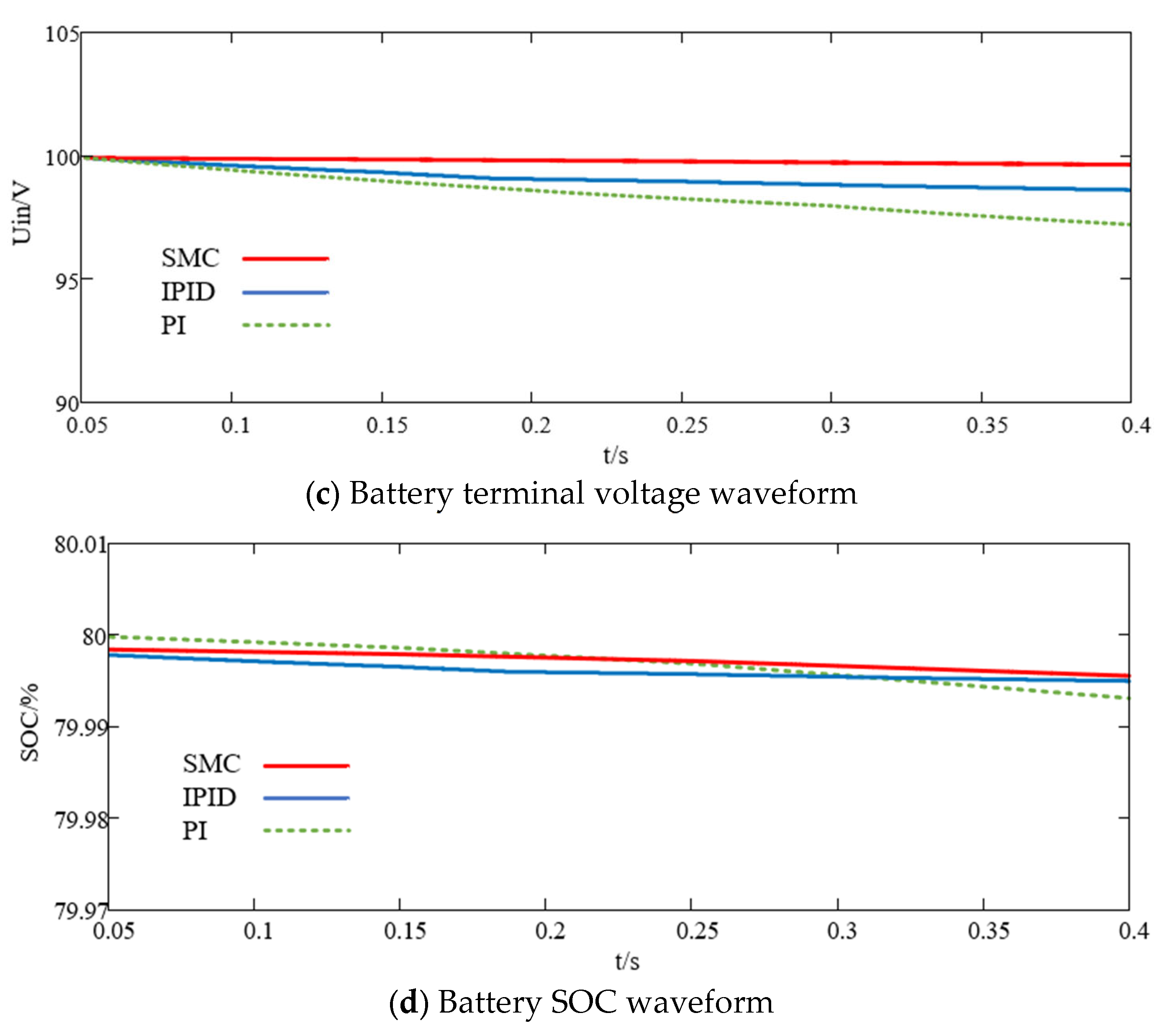
Figure 5a–d are DC bus voltage, total power, battery SOC and battery terminal voltage response waveforms under PI controller, respectively. At 0.15 s, the constant power load suddenly changes to 200 W, as well as a 250 Ω resistive is suddenly connected to the load in parallel. It can be seen that the DC bus voltage drops to 198.2 V, and recovers to 200 V after 0.03 s. At 0.25 s, the constant power load suddenly changes to 400 W, as well as a 250 Ω resistive load is suddenly connected to the load in parallel. It can be seen that the bus voltage drops to 197.1 V, and after 0.035 s, it returns to the reference voltage.
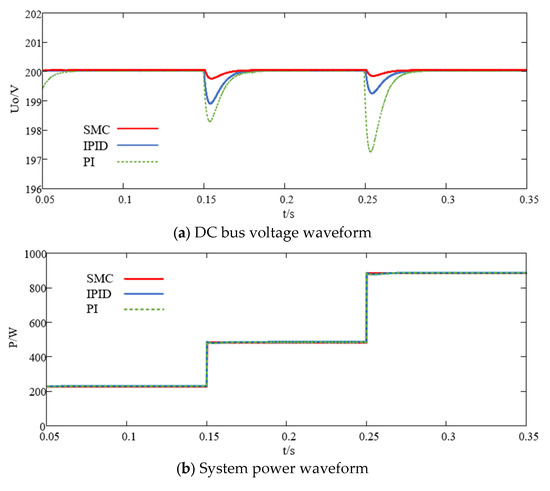
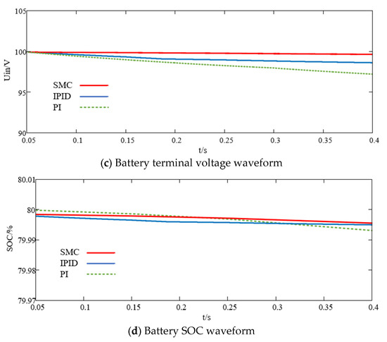
Figure 5.
State response under sudden load changes, (a) DC bus voltage waveform, (b) System power waveform, (c) Battery terminal voltage waveform, (d) Battery SOC waveform.
As a contrast, at 0.15 s, the bus voltage controlled by IPID drops to 198.8 V, and recovers to 200 V after 0.025 s. At 0.25 s, the bus voltage controlled by IPID drops to 199.3 V, and returns to the reference voltage after 0.02 s.
Meanwhile, at 0.15 s, the bus voltage of multivariable-feedback sliding-mode control drops to 199.7 V, and recovers to 200 V after 0.016 s. At 0.25 s, the bus voltage of sliding-mode control drops to 199.8 V, and returns to the reference voltage after 0.01 s.
Furthermore, in order to present a more comprehensive numerical comparison for scheme I, the three controllers’ performance are summarized in Table 2.
Table 2.
Comparison of SMC, IPID and PI with sudden load changes.
For the DC bus voltage disturbance caused by the suddenly change of the load, PI control method, IPID control method and the proposed multivariable sliding-mode control method all can maintain the stability of bus voltage to a certain extent. However, the proposed method not only accelerates the DC bus voltage adjust response speed, but also reduces the overshoot by 0.85 and 1.25% compared with PI control method, as well as 0.45 and 0.25% compared with the IPID control method, which reflects better transient and steady-state performance.
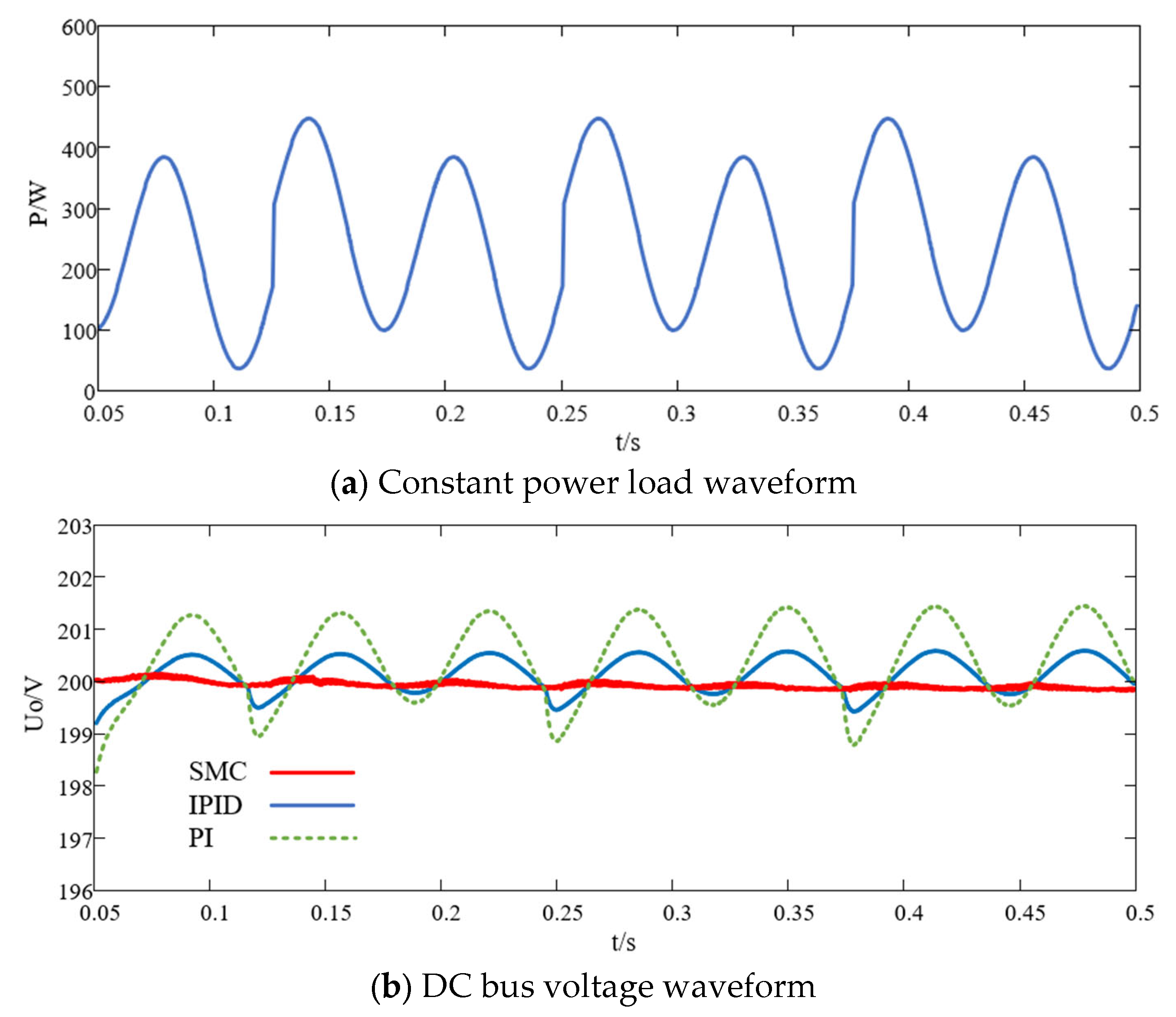
5.2. Scenario II: Simulation of Continuous Sudden Loads
Scheme II is to verify the influence of continuous random load variation on system stability. The resistive load value remains unchanged at 50 Ω, and the constant power load fluctuates continuously and randomly within a large range, as shown in Figure 6. Define voltage error rate eU to analyze voltage fluctuation as
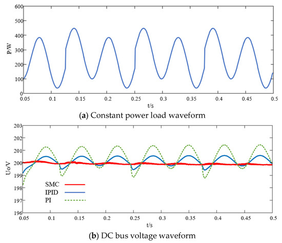
Figure 6.
State response under continuous load changes, (a) Constant power load waveform, (b) DC bus voltage waveform.
It can be seen from Figure 6 that when the load dynamic changes continuously and randomly, the response speed of the multivariable-feedback sliding-mode control method is faster than that of the PI control method. The maximum output voltage of the DC/DC converter using the PI control method is 201.8 V, and the voltage error is 0.75%. The minimum output voltage is 198.4 V, and the voltage error is 1.35%. As IPID controller, the control gain online switching makes the response speed close to that of the sliding-mode controller. However, due to a limited number of switching rules, it also produces certain overshoot and a long adjustment transition time. The maximum output voltage of the converter using the IPID control method is 200.5 V, and the voltage error is 0.25%. The minimum output voltage is 199.7 V, and the voltage error is 0.15%. As a contrast, the maximum voltage using the multivariable-feedback sliding-mode control method is 200.4 V, and the voltage error rate is 0.2%. The minimum output voltage is 199.6 V, and the voltage error rate is 0.2%.
Furthermore, in order to make a more comprehensive numerical comparison for scheme II, the three controllers’ performance can be summarized in Table 3.
Table 3.
Comparison of SMC, IPID and PI with continuous load changes.
Further analysis of Table 3 shows that the proposed multivariable sliding-mode control method has good nonlinear characteristics of soft approach and stronger anti-interference ability when the load is continuously and randomly mutated. Furthermore, the overall control effect is better than the traditional PI control method and IPID control method.
Through the comparison of a multi-scenario MATLAB/Simulink simulation, it can be noticed from further analysis that the proposed multivariable-feedback sliding-mode control method has the following advantages:
Due to the defined three controlled state variables, including output voltage error x1, inductor current error x2 and its integral x3, it is beneficial to express various dynamic characteristics of the DC bus voltage fluctuation process.
Due to the defined multivariable weight combination based sliding-mode surface S, it is beneficial to coordinate the weight relationship of the convergence speed of the three controlled state variables by adjusting its parameters α1, α2, α3. This improves the coordination and steady-state accuracy of the DC bus voltage control.
Due to the defined nonlinear fast power reaching law Equation (17), it is beneficial to coordinate the trajectory shape of the convergence acceleration of the sliding surface by adjusting its parameters m1, m2, m3. This improves the speed and controllability of the DC bus voltage control.
The proposed multivariable-feedback sliding-mode control method has the characteristics of rapid response, small fluctuation range, smooth trend and no overshoot, etc., which can make the DC bus voltage maintain excellent dynamic and steady-state robust stability under the condition of load power perturbation.
6. Experimental Verification
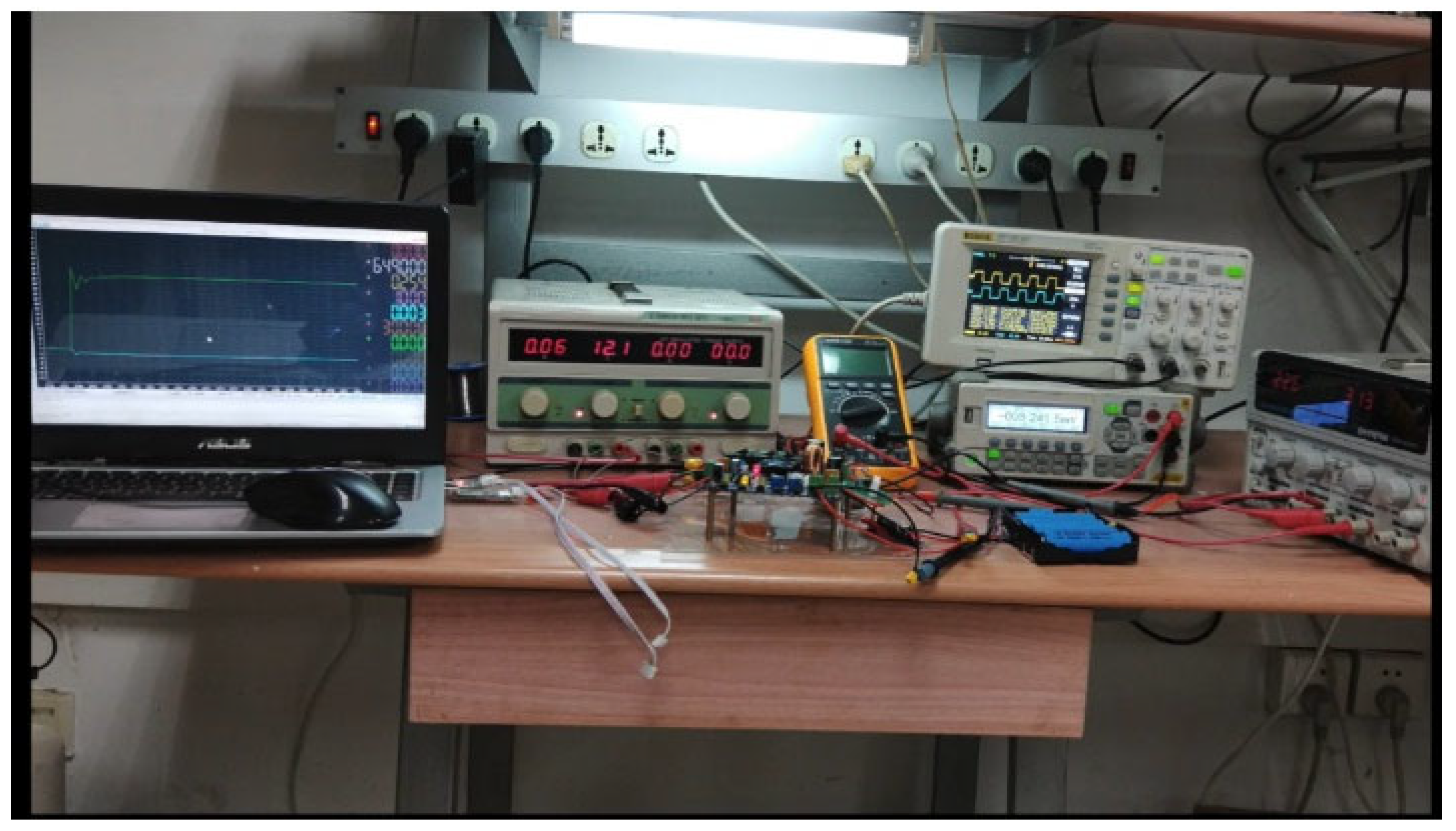
In order to verify the accuracy and rationality of the proposed multivariable-feedback sliding-mode control, a corresponding bidirectional DC/DC converter experimental platform was built in the laboratory, according to Figure 2.
The experimental platform is shown in Figure 7. A TI company TMS320F28335 processor was adopted as the main control chip of the bidirectional DC/DC converter. This processor has the advantages of low power consumption, multiple peripherals, stability and is not easy to be interfered with. The converter current measurement circuit uses 10 mΩ copper wire as sampling resistance, copper wire resistance is small, low temperature coefficient, has good stability, minimal impact on the main circuit, and is suitable for current sampling. When the current flows through the main circuit, the tiny voltage difference at both ends of the copper wire is input to the ADC channel of TMS320F28335 after the amplifier signal conditioning circuit.

Figure 7.
Experimental platform picture.
The bidirectional DC/DC converter adopted a single pole PWM trigger method. The power drive chip IR2104 and the optocoupler chip 6N137 were used to design the PWM power drive circuit. The advantages of IR2104 driver chip are its strong driving ability and high cost-effectiveness. The MOS tube of the bidirectional DC/DC converter was selected as SiC N-Channel MOSFET. This MOS tube is suitable for advanced high-efficiency switching applications.
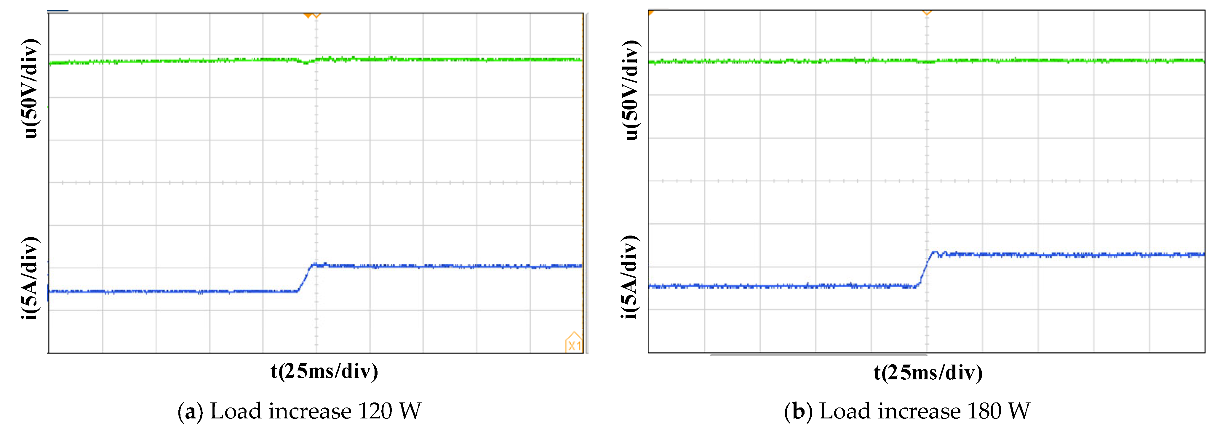
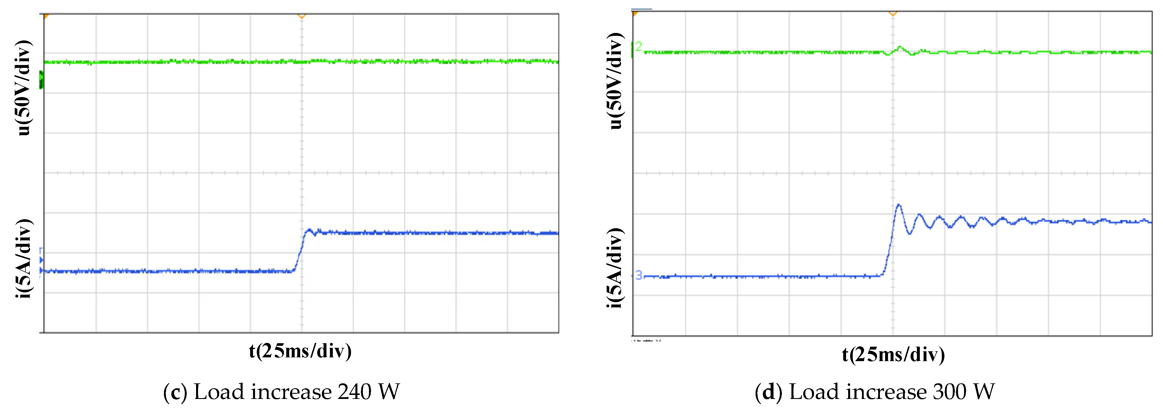
Figure 8 is the response waveform of the DC bus voltage and the battery terminal current when the load suddenly increases under different load conditions.
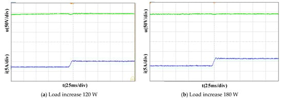
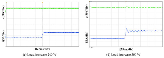
Figure 8.
Experimental waveform under load suddenly increases, (a) Load increase 120 W, (b) Load increase 180 W, (c) Load increase 240 W, (d) Load increase 300 W.
In Figure 8, the green curve is the DC bus voltage response waveform, and the blue curve is the battery current response waveform. In Figure 8a–d, the output current of the battery stabilizes at 2 A at the beginning, and rapidly increases to 4.4, 5.6, 6.6, 7.8 A after the load suddenly increases. The fluctuation range of DC bus voltage caused by the load suddenly increasing is about 4.9, 5.1, 5.2, 5.4 V.
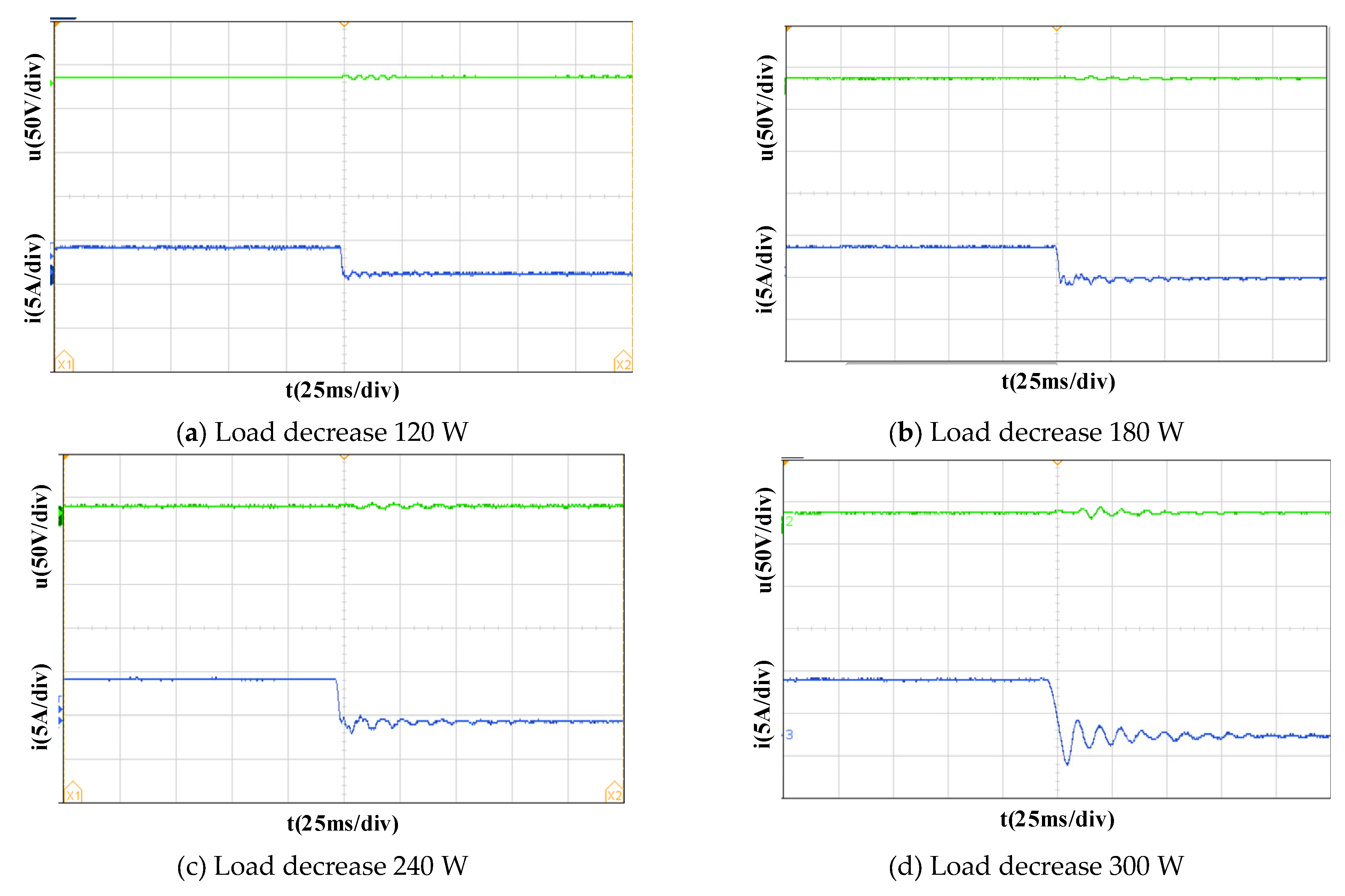
Figure 9 is response waveforms of the DC bus voltage and battery terminal current when the load suddenly decreases under different load conditions.
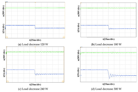
Figure 9.
Experimental waveform under load suddenly decreases, (a) Load decrease 120 W, (b) Load decrease 180 W, (c) Load decrease 240 W, (d) Load decrease 300 W.
In Figure 9, the green curve is the DC bus voltage response waveform; the blue curve is the battery current response waveform. In Figure 9a–d, the output current of the battery is stable at 7.5 A at the beginning, and then rapidly decreases to 5.1, 4, 2.9, 1.8 A after the load suddenly decreases. The bus voltage fluctuation range caused by the load suddenly decreasing is about 4.8, 5, 5.2, 6 V.
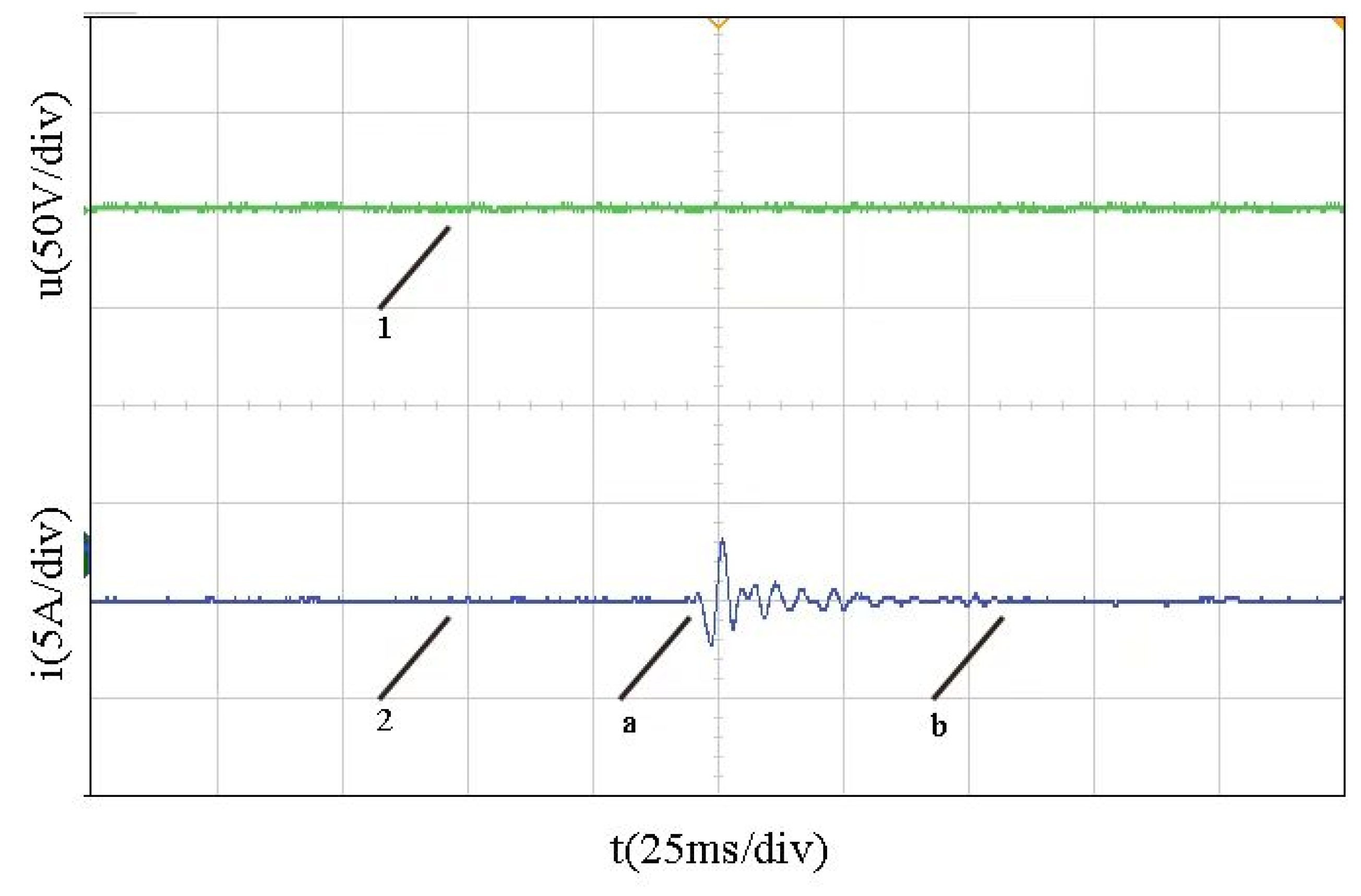
Figure 10 is the response waveform of the DC bus voltage and battery terminal current when the load continuously dynamically fluctuates. Curve 1 is the DC bus voltage, and curve 2 is the battery current. The system is stable at the beginning, and the initial constant power load is 100 W. From point a, the constant power load fluctuates continuously and randomly in a large range of 200 W. When it reaches point b, the load fluctuation stops and the system returns to stability. The continuous fluctuation of the load causes the bus voltage to fluctuate about 3.6 V.
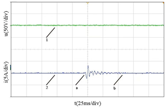
Figure 10.
Experimental waveform with continuous load fluctuation.
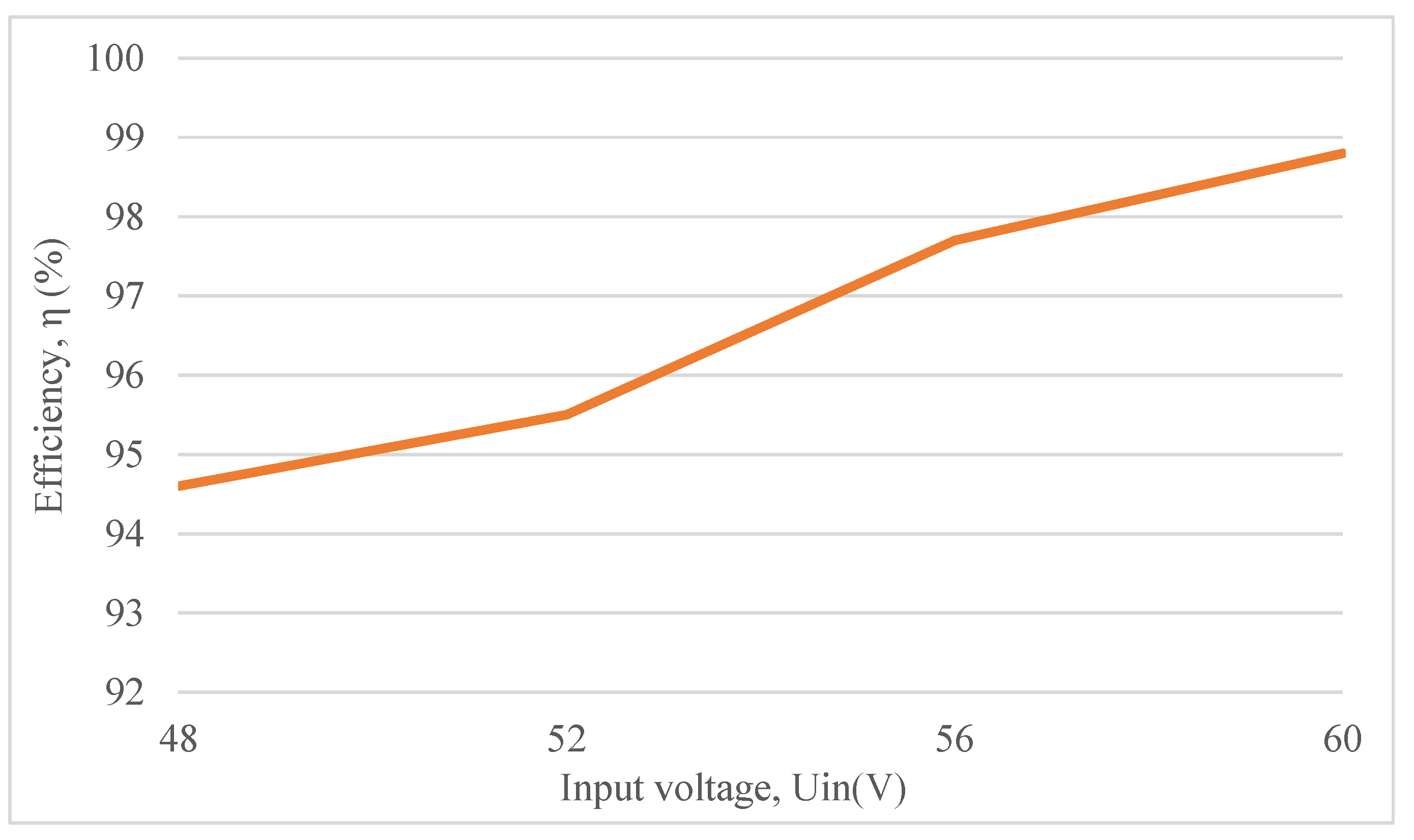
Figure 11 is a line diagram of the converter efficiency at different input voltages. Set the initial input voltage to 48 V, and define the input voltage from small to large with a 4 V step value. With the increase of input voltage, the efficiency of the converter increases monotonously and remains above 90%.

Figure 11.
Converter efficiency under different input voltages.
It is generally believed that the difference between the experimental results and the simulation results mainly comes from the simplification of various components when building the simulation model. Simulation is the ideal modeling of the circuit, the actual bidirectional DC/DC converter circuit is much more complex than the simulation circuit model, which will lead to the experimental response waveform generated by the ripple being slightly larger than the simulation waveform. In terms of the two schemes of comprehensive load suddenly increasing, suddenly decreasing and load continuously fluctuating, the experimental response waveforms are basically the same as the simulation waveforms.
The experimental results show that the sliding-mode control method can not only effectively suppress DC bus voltage fluctuations and improve the stability of the bidirectional DC/DC converter, but also make a fast dynamic response when the system load changes.
7. Conclusions
In this paper, a multivariable-feedback sliding-mode control method for bidirectional DC/DC converters applied in a DC microgrid is designed, aiming at the nonlinear characteristics of the DC microgrid with a constant power load, which easily leads to system instability. The output voltage error, inductor current error and its integral are used as the control law state variables to ensure the stability of the DC microgrid with a dynamic constant power load. The fast power reaching law is introduced into the sliding-mode controller to improve the response speed and suppress chattering. The experimental and simulation results show that the proposed multivariable-feedback sliding-mode control method can obviously reduce the fluctuation of DC bus voltage and expand the stability range of the system. Compared with the traditional PI controller and IPID controller, the proposed method has more effective ability to suppress the change of system state parameters, which reflects better adaptability and robustness than that of the two other control methods.
Author Contributions
Conceptualization, Y.Y. and J.M.; software, Y.Y. and R.L.; validation, J.M.; formal analysis, J.M.; investigation, J.M. and R.L.; data curation, Y.Y. and R.L.; writing—original draft preparation, Y.Y.; writing—review and editing, J.M. and Y.Y.; supervision, J.M.; project administration, J.M.; funding acquisition, J.M. All authors have read and agreed to the published version of the manuscript.
Funding
This work is financially supported in part by Natural Science Research Program of Jiangsu Colleges and Universities under Grant No. 20KJA470002, Excellent Teaching Team of “Qinglan Project” of Jiangsu Colleges and Universities, and Science and Technology Research Program of Nantong under Grant No. JC2020094 and MS22020022.
Institutional Review Board Statement
Not applicable.
Informed Consent Statement
Not applicable.
Data Availability Statement
Not applicable.
Conflicts of Interest
The authors declare no conflict of interest.
References
- Shivam; Ratna, D. Stability analysis of islanded DC microgrid for the proposed distributed control method with constant power loads. J. Comput. Electr. Eng. 2018, 70, 151–162. [Google Scholar] [CrossRef]
- Can, E. A new multi-level inverter with reverse connected dual dc to dc converter at simulation. J. Int. J. Model. Simul. 2022, 42, 34–46. [Google Scholar] [CrossRef]
- Sahri, Y.; Belkhier, Y.; Tamalouzt, S.; Ullah, N.; Shaw, R.N.; Chowdhury, M.S.; Techato, K. Energy management system for hybrid PV/wind/battery/fuel cell in microgrid-based hydrogen and economical hybrid battery/super capacitor energy storage. J. Energy 2021, 14, 5722. [Google Scholar] [CrossRef]
- Al Alahmadi, A.A.; Belkhier, Y.; Ullah, N.; Abeida, H.; Soliman, M.S.; Khraisat, Y.S.H.; Alharbi, Y.M. Hybrid wind/PV/battery energy management-based intelligent non-integer control for smart DC-microgrid of smart university. J. IEEE Access 2021, 9, 98948–98961. [Google Scholar] [CrossRef]
- Xiao, H.; Wu, Q.; Xi, H. Analysis and design of a wide range ZVS/ZCS push–pull DC/DC converter with voltage clamped. J. IET Power Electron. 2022, 15, 422–433. [Google Scholar] [CrossRef]
- Babenko, V.P.; Bityukov, V.K.; Simachkov, D.S. DC/DC Buck-Boost Converter with Single Inductance. J. Russ. Microelectron. 2021, 50, 471–480. [Google Scholar] [CrossRef]
- Saadatizadeh, Z.; Chavoshipour, H.P.; Sabahi, M.; Liang, X. Multi-input multi-phase transformerless large voltage conversion ratio DC/DC converter. J. Int. J. Circuit Theory Appl. 2021, 49, 4294–4315. [Google Scholar] [CrossRef]
- Yang, N.; Damien, P.; Gao, F.; Abdellatif, M.; Liu, M. Compensation of droop control using common load condition in DC microgrids to improve voltage regulation and load sharing. J. Int. J. Electr. Power Energy Syst. 2015, 64, 752–760. [Google Scholar] [CrossRef]
- Navid, V.; Shirin, Y.; Mohammad, H.K.; Jan, D.B.; Tomislav, D. Adaptive TS Fuzzy-Based MPC for DC Microgrids with Dynamic CPLs: Nonlinear Power Observer Approach. J. IEEE Syst. J. 2019, 13, 3203–3210. [Google Scholar]
- Mary, A.H.; Miry, A.H.; Miry, M.H. System uncertainties estimation based adaptive robust backstepping control for DC DC buck converter. J. Int. J. Electr. Comput. Eng. 2021, 11, 347–355. [Google Scholar] [CrossRef]
- Kevin, E.L.M.; Plaza, G.; Douglas, A. Novel Robust Methodology for Controller Design Aiming to Ensure DC Microgrid Stability Under CPL Power Variation. J. IEEE Access 2019, 7, 64206–64222. [Google Scholar]
- Yazan, M.A.; Vadim, U.; Mohammed, A.H.; Longya, X. Sliding mode control of power converters: DC/DC converters. J. Int. J. Control 2018, 91, 2472–2493. [Google Scholar]
- Vidhya, S.D.; Balaji, M. Hybrid fuzzy PI controlled multi-input DC/DC converter for electric vehicle application. J. Autom. 2020, 61, 79–91. [Google Scholar] [CrossRef]
- Khairul, E.; Monzurul, K.A.; Shaikh, M.F.; Soad, S. Modelling and Simulation of DC-DC Boost Converter using Sliding Mode Control. J. Int. J. Recent Technol. Eng. 2020, 9, 674–678. [Google Scholar]
- Bahman, T.; Mahsa, S.; Mohammad, A.B.; Payam, F. A New Controller for DC-DC Converters Based on Sliding Mode Control Techniques. J. Control. Autom. Electr. Syst. 2019, 30, 63–74. [Google Scholar]
- Liu, L.; Zheng, W.; Ding, S. An Adaptive SOSM Controller Design by Using a Sliding-Mode-Based Filter and Its Application to Buck Converter. J. IEEE Trans. Circuits Syst. I Regul. Pap. 2020, 67, 2409–2418. [Google Scholar] [CrossRef]
- Guo, X.; Liu, Z. Adaptive Sliding Mode Control Design of Uncertain Switched Systems with Actuator Faults. J. Circuits Syst. Signal Processing 2021, 41, 1475–1496. [Google Scholar] [CrossRef]
- Abolvafaei, M.; Ganjefar, S. Adaptive second-order terminal PID sliding mode control design for integer-order approximation of wind turbine system for maximum power extraction. J. IET Control Theory Appl. 2021, 15, 2210–2220. [Google Scholar] [CrossRef]
- Michele, C.; Riccardo, L.; Sebastian, T. Sliding mode voltage control of boost converters in DC microgrids. J. Control Eng. Pract. 2018, 73, 161–170. [Google Scholar]
- Wang, J.; Rong, J.; Yu, L. Reduced-order extended state observer based event-triggered sliding mode control for DC-DC buck converter system with parameter perturbation. J. Asian J. Control 2020, 23, 1591–1601. [Google Scholar] [CrossRef]
- Baba, M.F.; Giridhar, A.V.; Narasimharaju, B.L. Nonisolated high gain hybrid switched-inductor DC-DC converter with common switch grounding. J. Int. J. Circuit Theory Appl. 2022, 50, 2810–2828. [Google Scholar] [CrossRef]
- Anitha, T.; Arulselvi, S. Design of linear and nonlinear controller for DC-DC boost converter with right-half plane zero. J. Int. J. Power Electron. 2022, 15, 116–130. [Google Scholar] [CrossRef]
- Zhang, Y.; Yin, Z.; Zhang, Y.; Liu, J.; Tong, X. A Novel Sliding Mode Observer with Optimized Constant Rate Reaching Law for Sensorless Control of Induction Motor. J. IEEE Trans. Ind. Electron. 2020, 67, 5867–5878. [Google Scholar] [CrossRef]
- Soliman, M.S.; Belkhier, Y.; Ullah, N.; Achour, A.; Alharbi, Y.M.; Al Alahmadi, A.A.; Abeida, H.; Khraisat, Y.S.H. Supervisory energy management of a hybrid battery/PV/tidal/wind sources integrated in DC-microgrid energy storage system. J. Energy Rep. 2021, 7, 7728–7740. [Google Scholar] [CrossRef]

Publisher’s Note: MDPI stays neutral with regard to jurisdictional claims in published maps and institutional affiliations. |
© 2022 by the authors. Licensee MDPI, Basel, Switzerland. This article is an open access article distributed under the terms and conditions of the Creative Commons Attribution (CC BY) license (https://creativecommons.org/licenses/by/4.0/).