
A Comprehensive Study on Next-Generation Electromagnetics Devices and Techniques for Internet of Everything (IoE)

 , , ,
, , ,  ,
, 

Abstract
1. Introduction
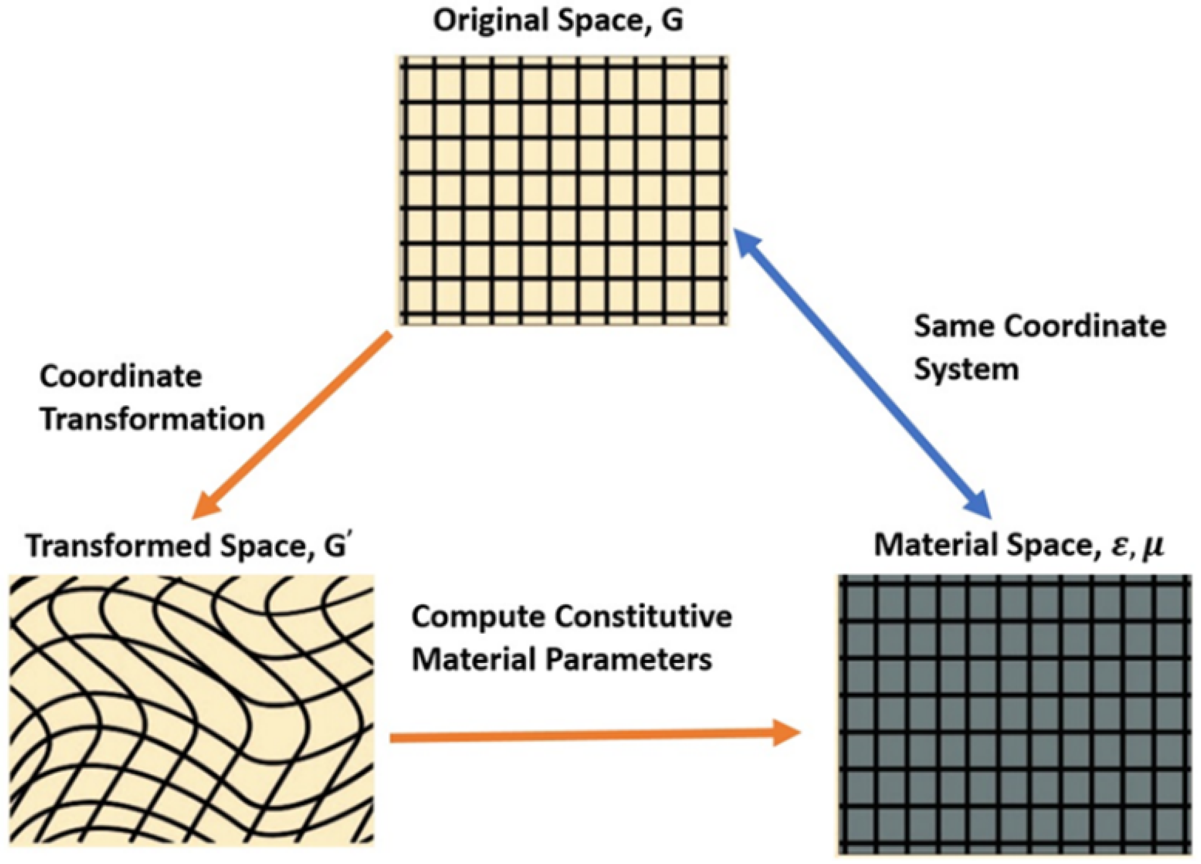
2. Transformation Electromagnetic/Optics
- I.
- Determine a known wave-material relation in the original coordinate system, i.e., a plane wave or a propagating Gaussian beam.
- II.
- Find the volume of space in the original coordinate system and the associated volume of space in the transformed coordinate system.
- III.
- Define the coordinate transformation you choose to map your original space to that new transformed space.
- IV.
- Compute the material parameters in the new transformed space using Equations (8) and (9).
- V.
- Translate the computed material parameters from the transformed space and acquire the desired material in the original coordinate system.
2.1. Unique Electromagnetics Devices Designed Using TE/TO
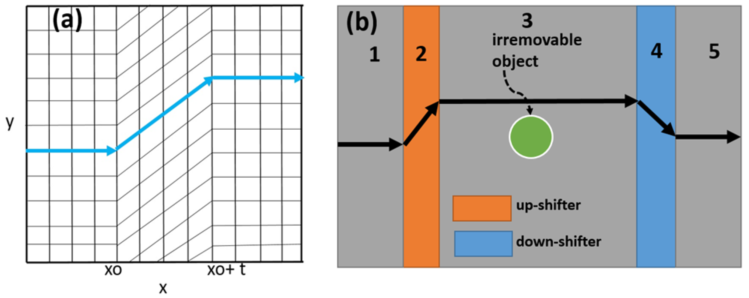
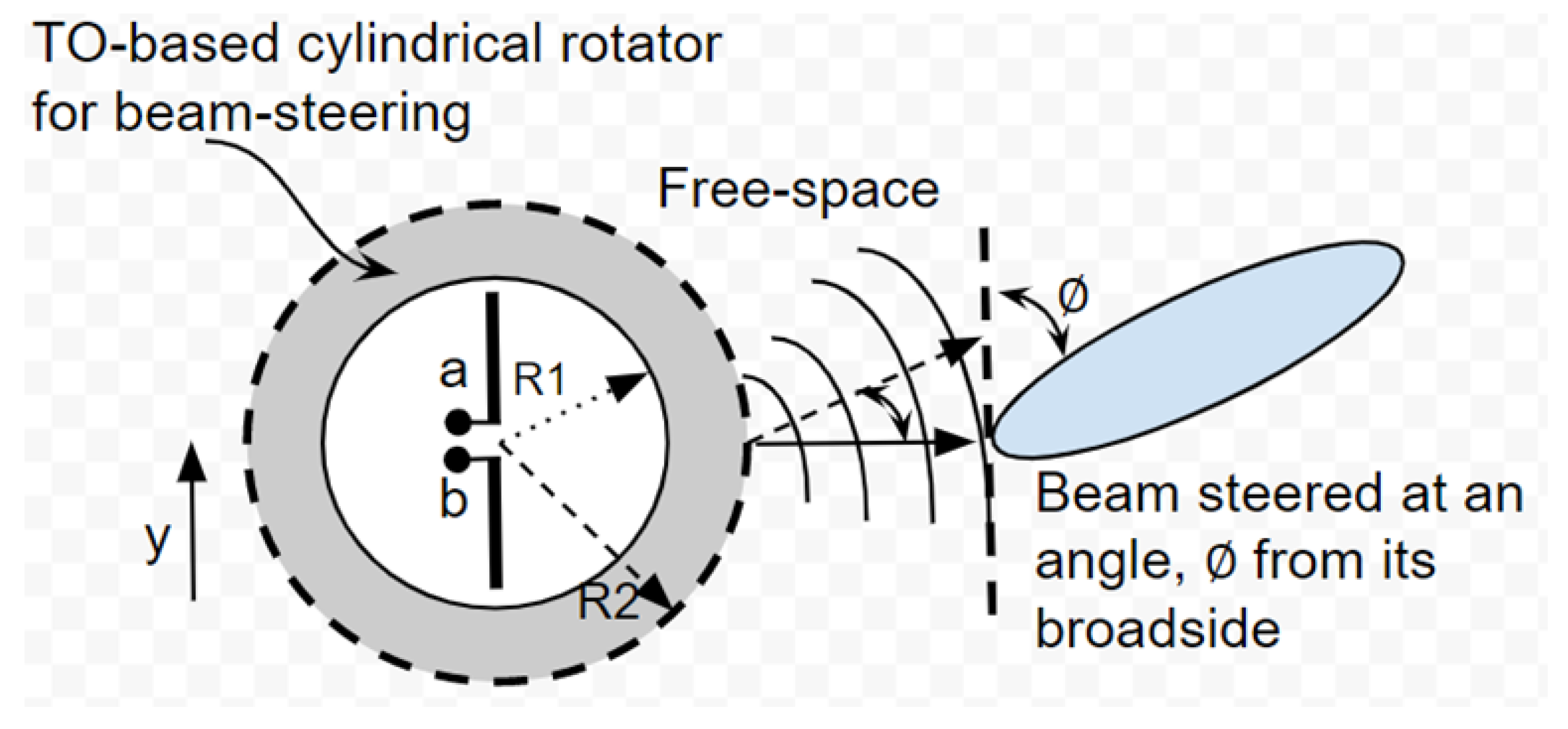
Beam-Shifters, Benders, and Rotators
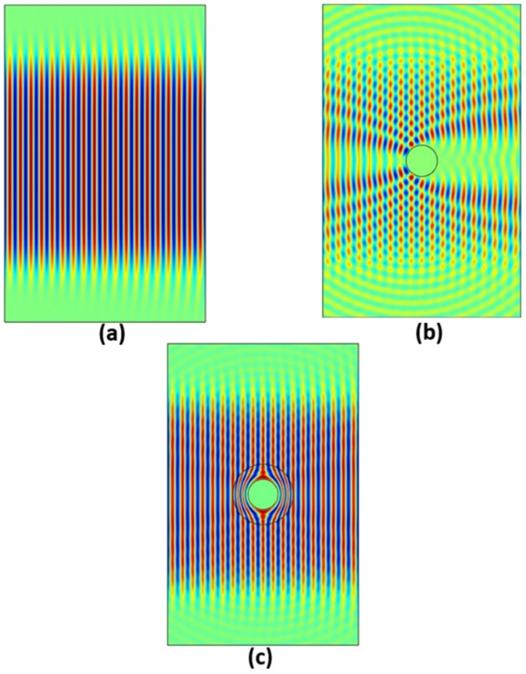
2.2. Electromagnetic Cloaking and It’s Applications in Antennas
Electromagnetic Source Transformation
3. Wireless Power Transfer
3.1. Near Field (Non-Radiative) WPT System
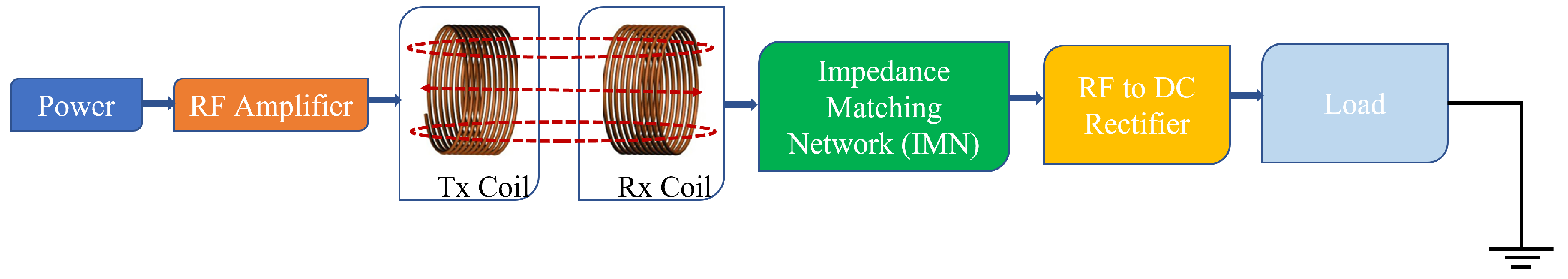
3.1.1. Inductive Coupling
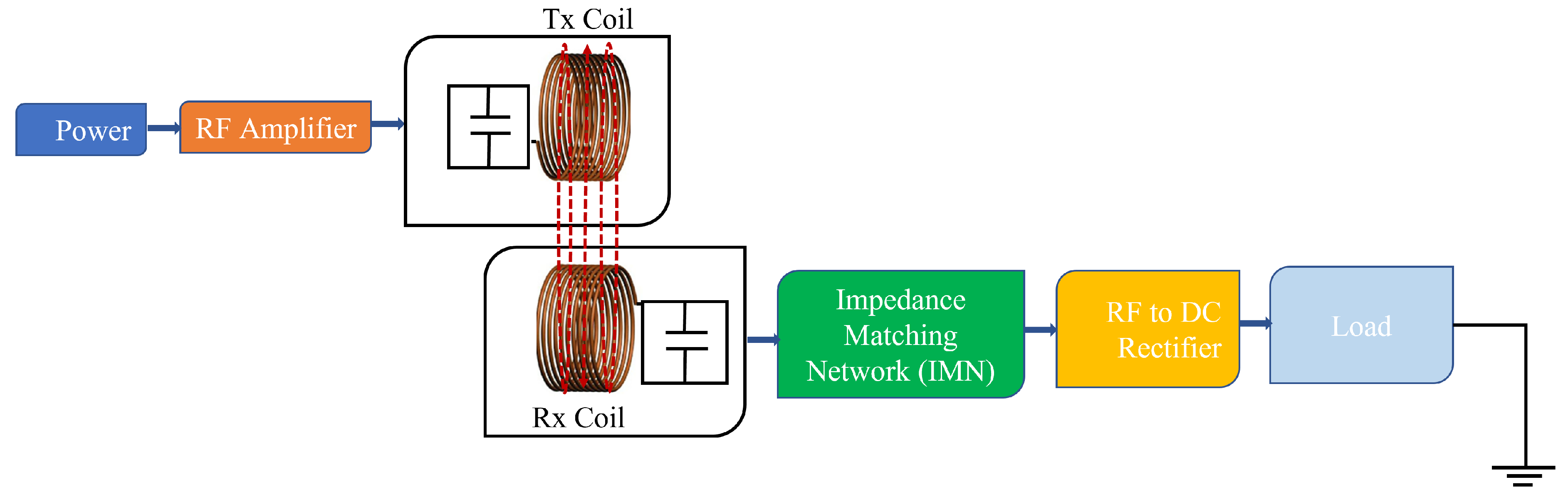
3.1.2. Magnetic Resonant Coupling
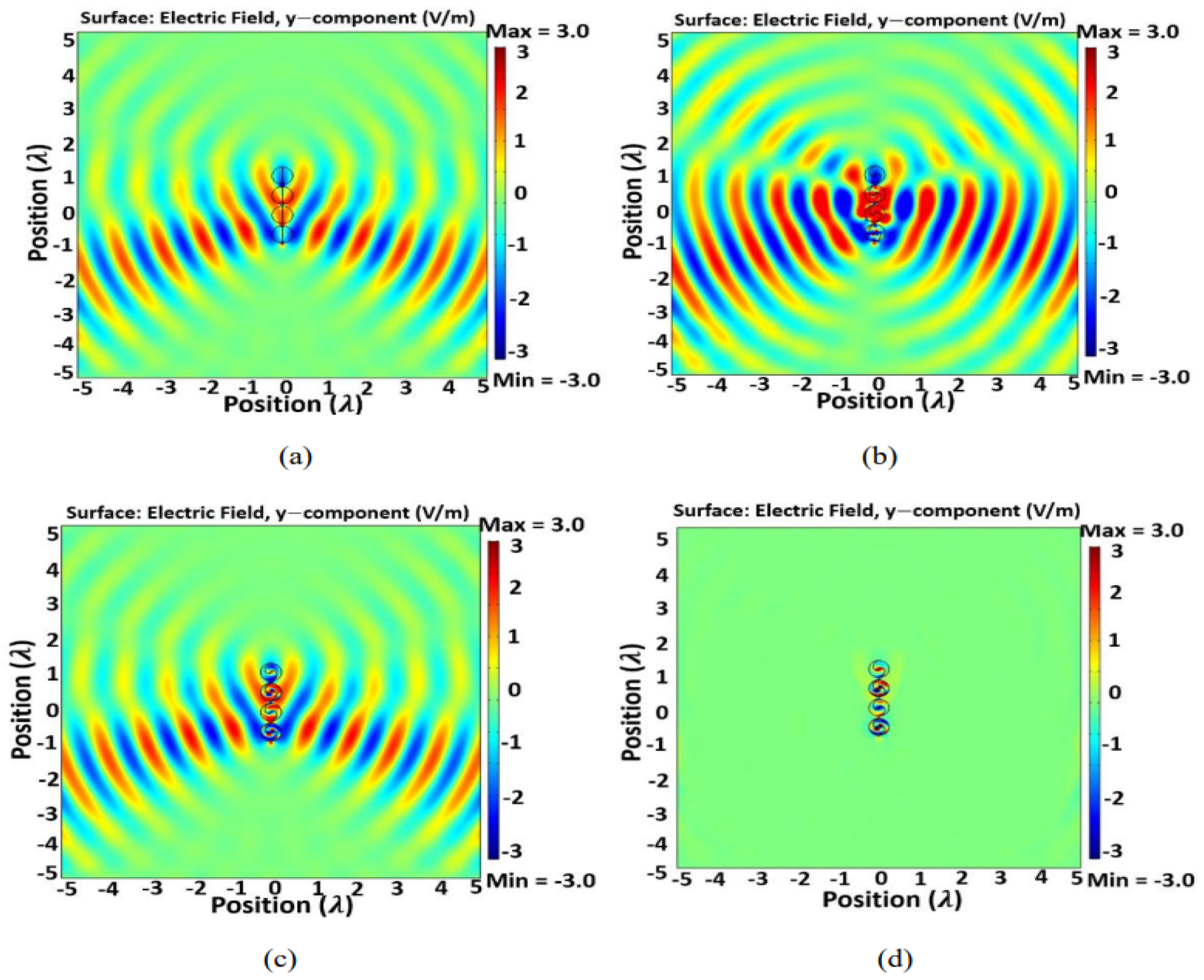
3.1.3. Strongly Coupled Magnetic Resonance
3.1.4. Capacitive Coupling
3.2. Far Field (Radiative) WPT System
3.2.1. Applications
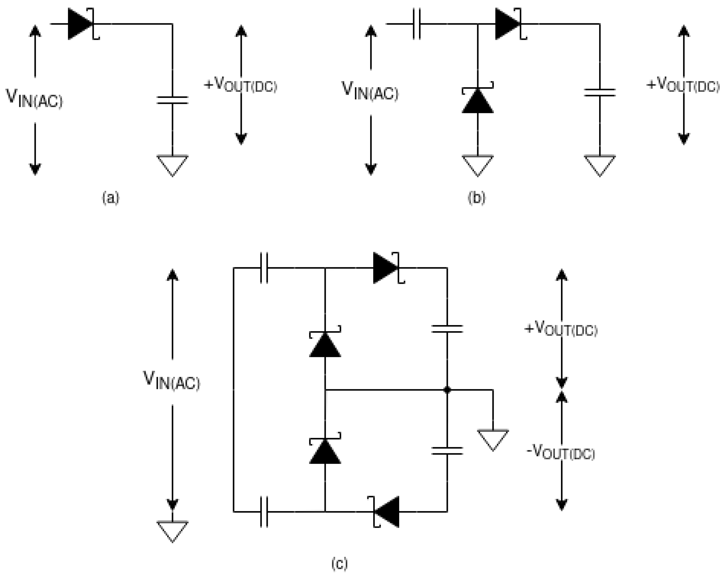
3.2.2. Methodology
3.2.3. High Directivity Antennas
3.2.4. Maximum Power Point Tracking
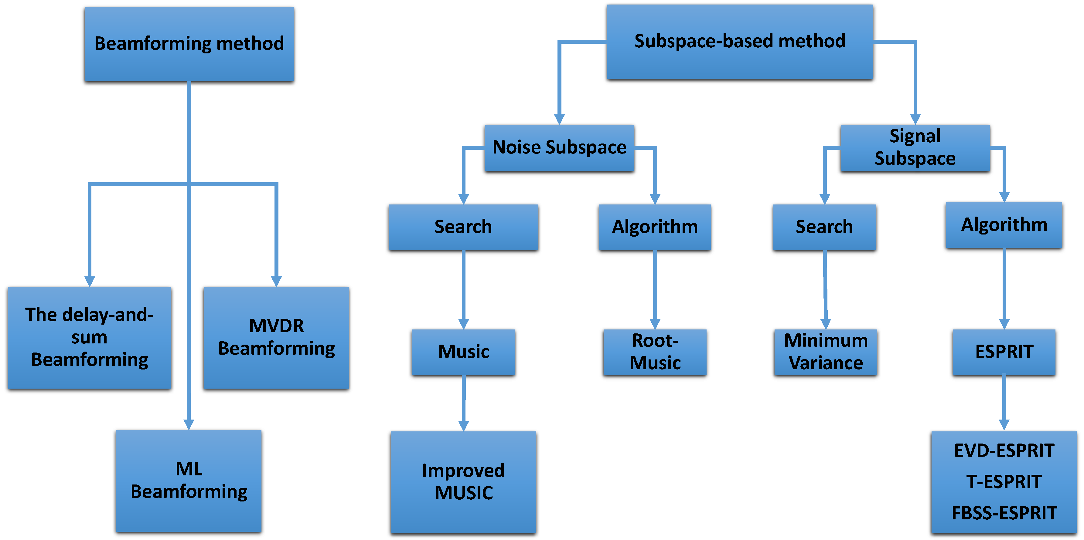
4. An Insight for Direction of Arrival Subspace-Based Algorithms along with Improved Coherent Signal Detection Technique
4.1. Algorithms Methodology
4.1.1. Minimum Variance Distortionless Response (MVDR) Beamforming
4.1.2. MUSIC Algorithm
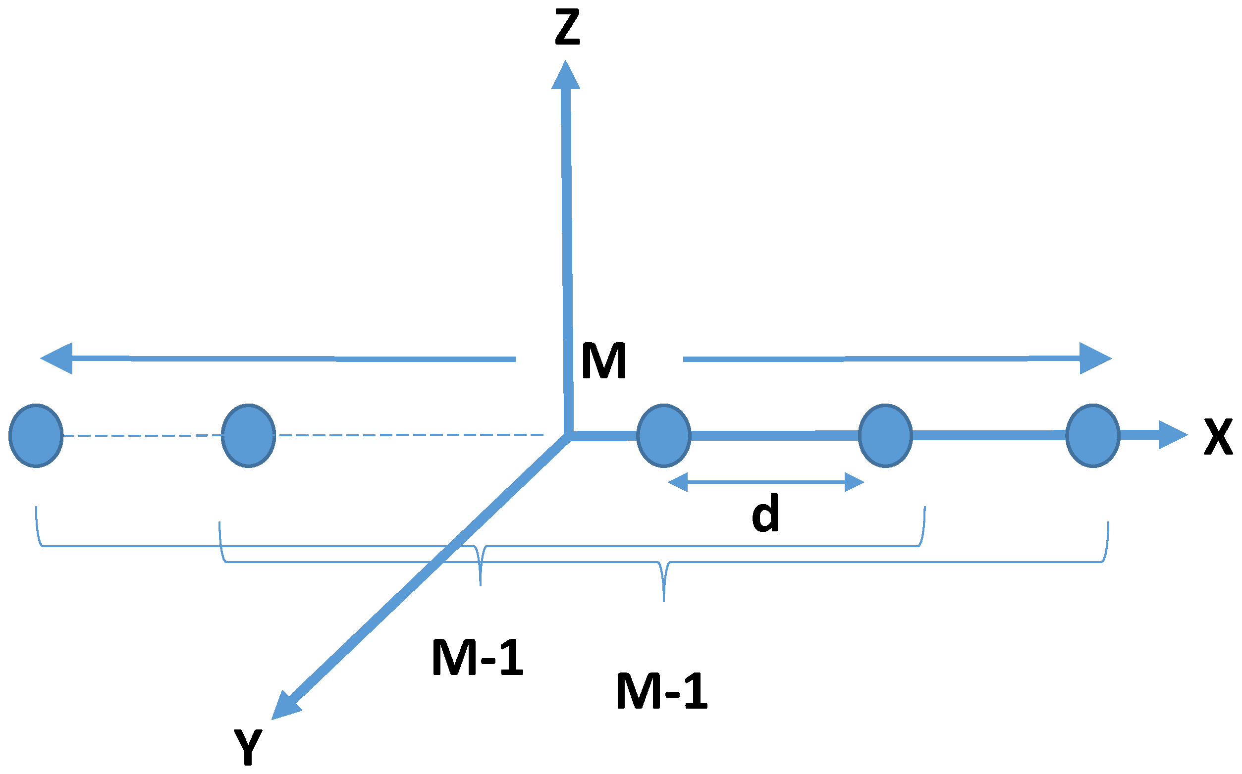
4.1.3. Conventional ESPRIT Algorithm (LS-ESPRIT)
4.2. SVD Technique for Coherent Sources (SVD-ESPRIT and Improved MUSIC)
4.3. Algorithm Improvement Techniques
4.3.1. Toeplitz Matrix Technique (T-ESPRIT)
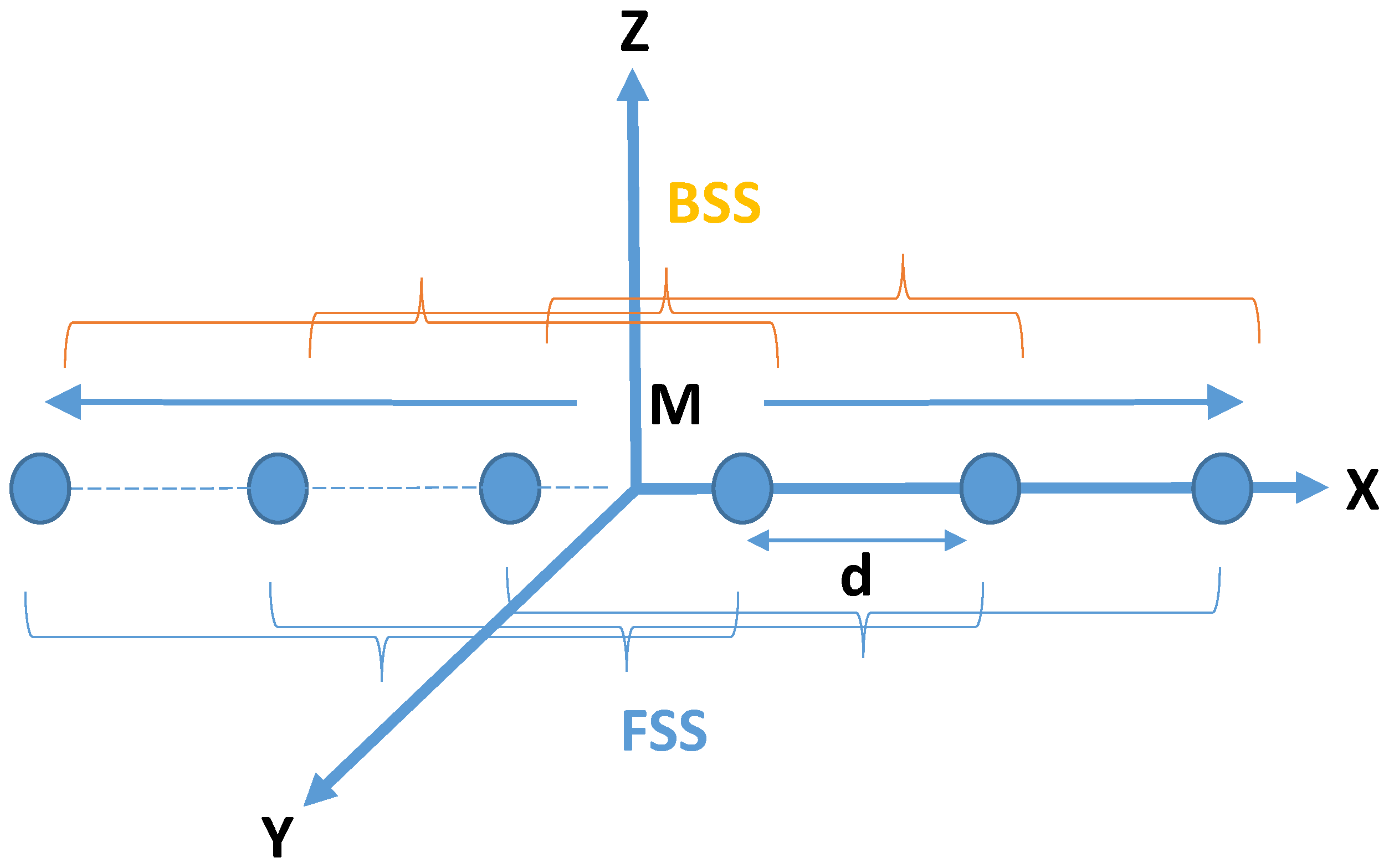
4.3.2. Forward/Backward Spatial Smoothing Technique (FBSS) (MSVD-ESPRIT)
5. Wireless Body Area Networks and Its Energy Harvesting Techniques for Health Care
5.1. Application of a WBANs
5.2. Medical Application
5.2.1. Cancer Application
5.2.2. Cardiovascular Application
5.2.3. Diabetes Application
5.2.4. Stress Application
5.2.5. Remote Monitoring
5.2.6. Fitness, Performance, and Well-Being Tracking
5.3. Nonmedical Application
5.3.1. Lifestyle and Entertainment Application
5.3.2. Sports
5.3.3. Emergency
5.3.4. Military Purpose
5.4. Characteristics of WBAN
5.4.1. Difference between WBAN and WSN
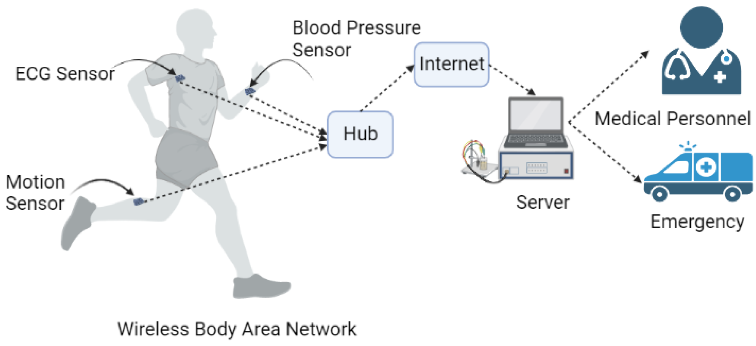
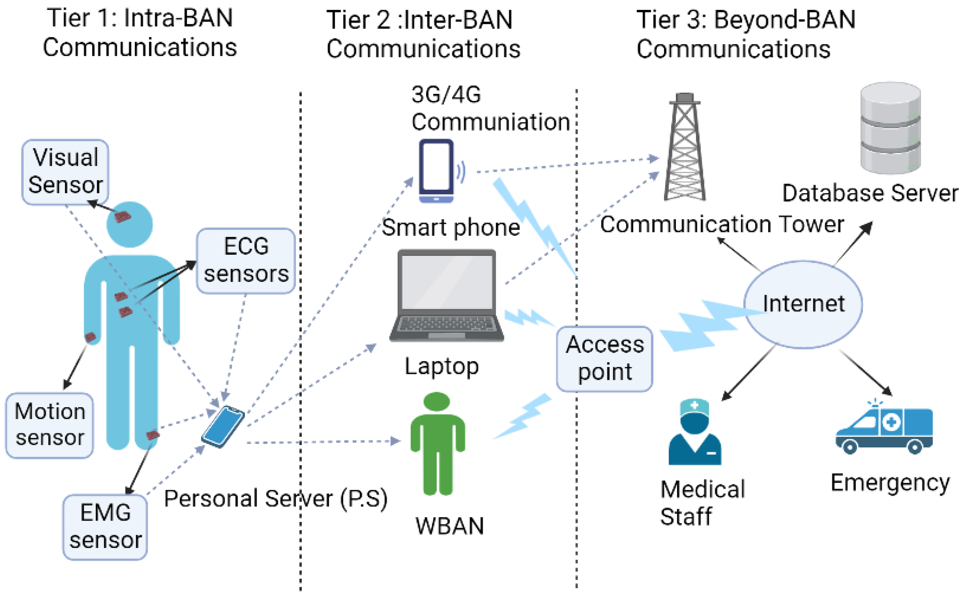
5.4.2. General Architecture of WBAN
- First-tier of WBAN architecture is realized by body sensor units that are placed either outside or inside of the human body. These sensors detect the physiological data signals from the human body, convert it to digital forms, and then transmit through wireless from the human body and finally send it wirelessly to the second tier. This communication is also known as intra-BAN communication.
- The Second-tier builds a connection between the first-tier and third-tier wirelessly. The second tier is also known as inter-BAN communication and consists of personal server units. These units get data from sensors, process it, and format the processed results to convey to the upper, third-tier if necessary.
- Third-tier comprises of user machines, where end users are data experts who involves decision making based on the data from tier-2 such as sending some caretaker or ambulance to the patient, taking some specific diet for the sportsman.
5.5. Technologies Enabling WBAN
5.5.1. Bluetooth
5.5.2. Bluetooth Low Energy (BLE)
5.5.3. Zigbee/IEEE 802.15.4
5.5.4. WiFi
5.6. Hardware and Devices Used in WBAN System
5.7. WBAN System Requirements
5.7.1. Power Source and Patients’ Safety
5.7.2. Data Rate
5.7.3. Size and Form Factor of Sensors
5.7.4. Antenna and Surrounding Medium Specification
5.7.5. Security
5.8. Energy Harvesting and WBAN
5.8.1. Wireless Power Transfer (WPT)
5.8.2. Other Energy Harvesting Techniques for Wearable Devices for WBAN
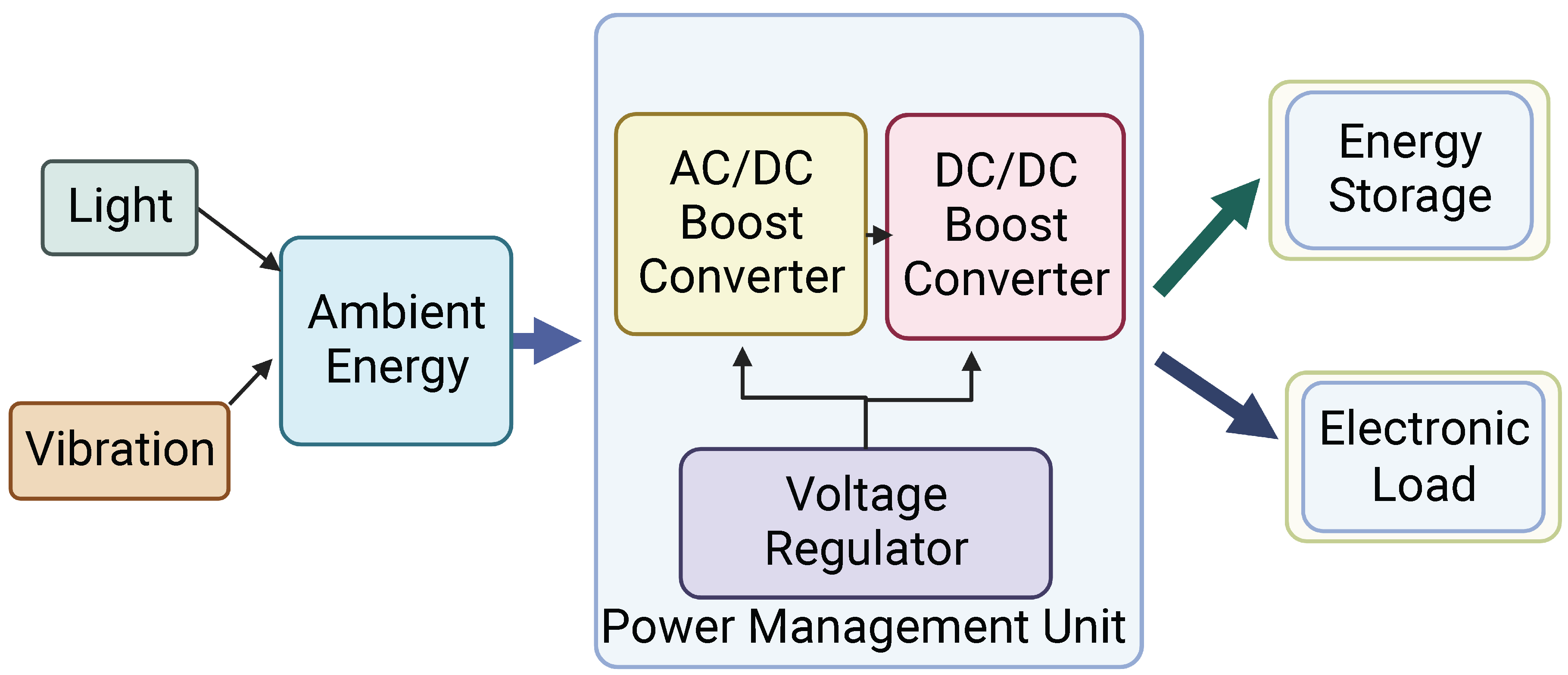
- (a)
- Ambient energy: light and vibrational energies can be good sources of energy.
- (b)
- AC-DC/DC-DC converter: this block is used either to convert the AC output from some harvesters into DC or from one DC to another DC level [218].
- (c)
- Voltage Regulators: these are used to maintain the voltage level within an acceptable range for energy storage and load stages [218].
- (d)
- Energy Storage: Here, the characteristics of the storage module are dependent on the specifications of the targeted application [218].
5.8.3. Summary of Energy Harvesting Techniques and Their Performance
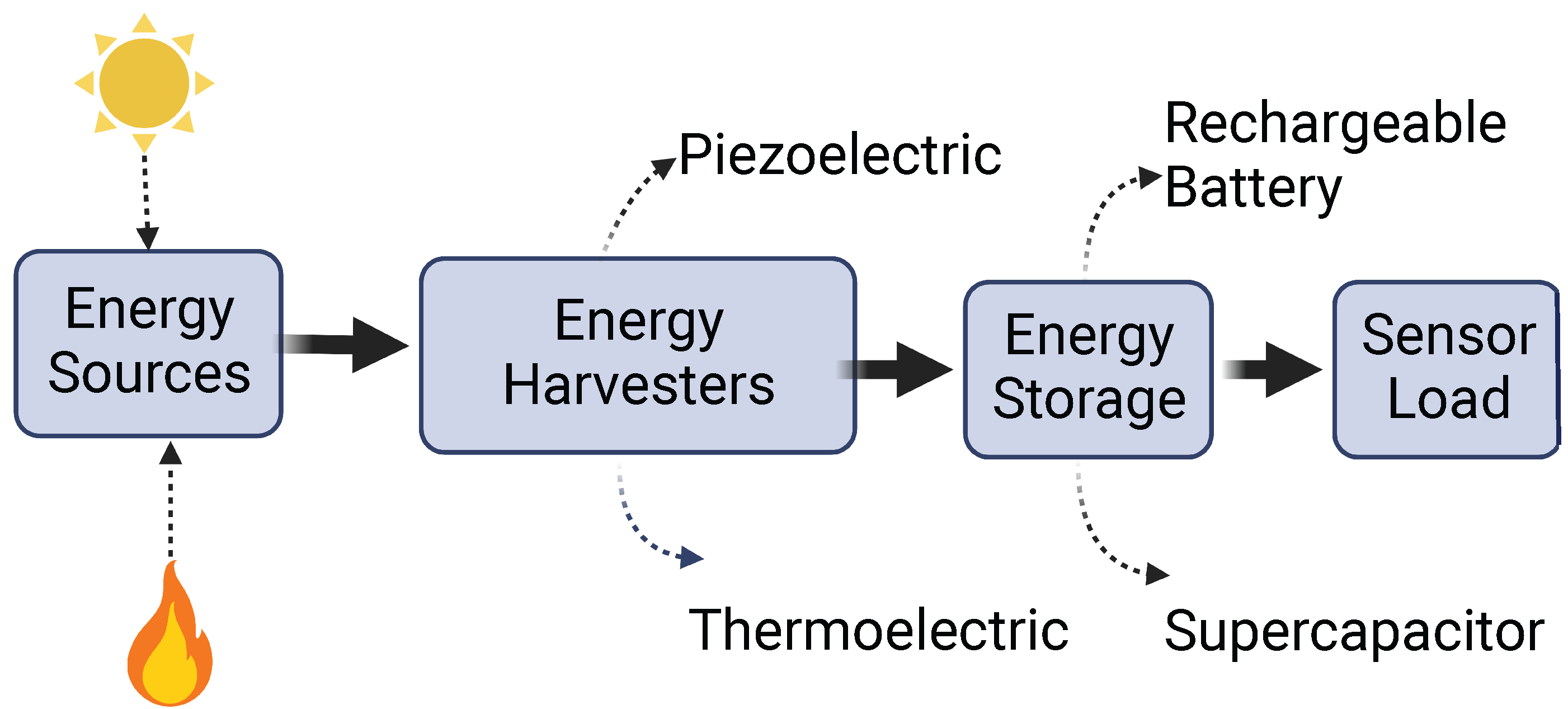
5.8.4. Energy Harvesting Sources
5.8.5. Comparison of Energy Harvesters Based on Their Power Densities and Application
5.9. Challenges of WBAN
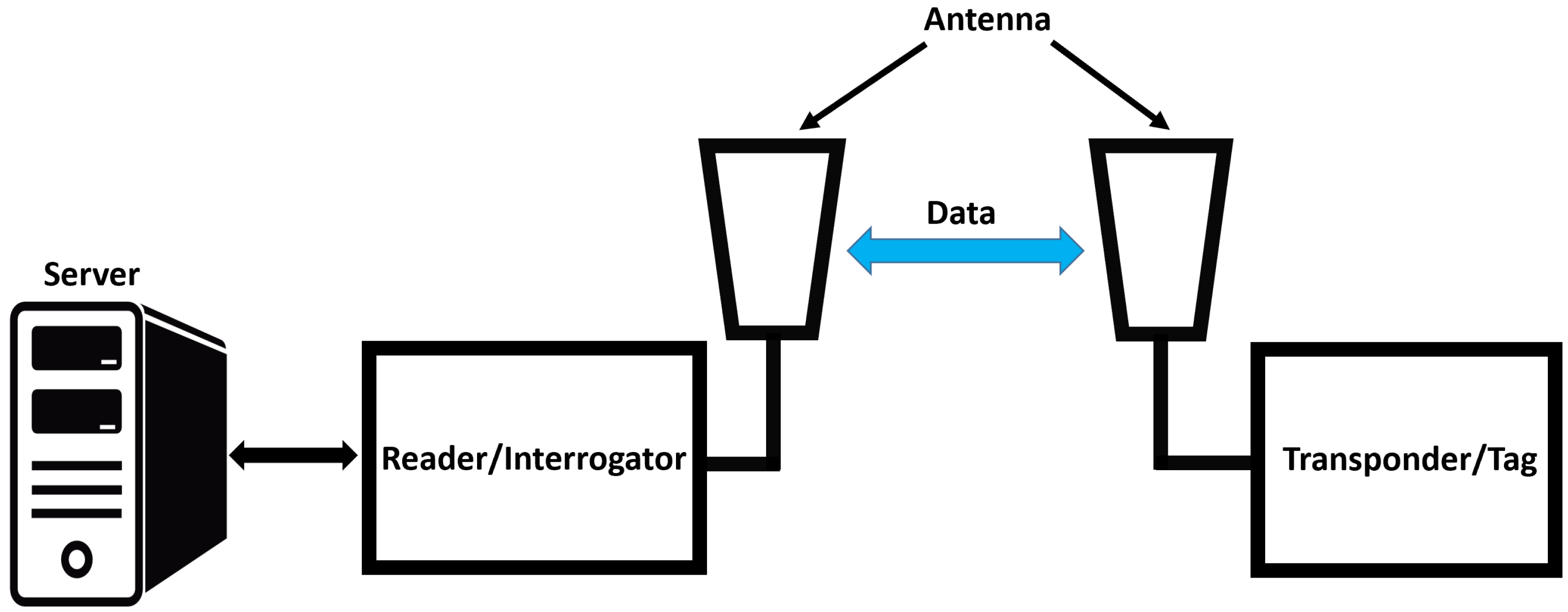
6. RFID in Biomedical and Healthcare Application
7. Sub-6 GHz 5G Systems
7.1. Single Element Antennas for Sub-6 GHz 5G Systems
7.1.1. PIN Diode Switching Integration
7.1.2. Slotted Antennas
7.1.3. Multiple Feeding Techniques
7.2. Overview of Recent Works on Single Element Antenna for Sub-6 G Hz 5G Applications
7.3. Multiple Element Antenna and Array
Present Shortcomings
- (1)
- The majority of the systems were designed with two elements only whereas increasing the number of elements has certainly been proved to be for enhanced data rate and channel capacity. There are some works on eight [277] or even ten elements [278], however either the performance has severely been degraded or some key performance parameters, including Envelope Correlation Coefficient (ECC), DG, MEG and isolation, have not been mentioned. Besides, the overall size and edge-to-edge distance between elements of the MIMO was found to be an issue while keeping the performance and compactness up to the mark simultaneously.
- (2)
- Consistent performance was not achieved throughout the whole band of operation as observed. For example, efficiency of the antenna was found to be degraded at the higher frequencies [279] which was the case for ECC also. The channel capacity and DG normally improves as more elements are added, however, maintaining ECC below 0.5 and better isolation between elements becomes more challenging.
- (3)
- Performance of the antennas, those are designed for handheld devices, is prone to degrade further. In this case, positioning of the elements of the MIMO is crucial.
- (4)
- Although many articles have intended to design antenna systems for a wide range of frequency in sub-6 GHz region, owing to the reasons mentioned above effective operation is not possible for at the frequencies they are designed for. In other words, the above constraints have made the MIMO antennas limited in terms of their operation.
8. Conclusions
Author Contributions
Funding
Conflicts of Interest
References
- Vandebroek, S.V. 1.2 Three pillars enabling the Internet of Everything: Smart everyday objects, information-centric networks, and automated real-time insights. In Proceedings of the 2016 IEEE International Solid-State Circuits Conference (ISSCC), San Francisco, CA, USA, 31 January–4 February 2016; pp. 14–20. [Google Scholar] [CrossRef]
- Tian, S.; Zhang, X.; Wang, X.; Han, J.; Li, L. Recent advances in metamaterials for simultaneous wireless information and power transmission. Nanophotonics 2022. [Google Scholar] [CrossRef]
- Markvart, A.; Song, M.; Glybovski, S.; Belov, P.; Simovski, C.; Kapitanova, P. Metasurface for Near-Field Wireless Power Transfer With Reduced Electric Field Leakage. IEEE Access 2020, 8, 40224–40231. [Google Scholar] [CrossRef]
- Wu, Y.; Gao, X.; Zhou, S.; Yang, W.; Polyanskiy, Y.; Caire, G. Massive access for future wireless communication systems. IEEE Wirel. Commun. 2020, 27, 148–156. [Google Scholar] [CrossRef]
- Roh, Y.; Lee, S.H.; Kang, B.; Wu, J.W.; Ju, B.K.; Seo, M. Terahertz optical characteristics of two types of metamaterials for molecule sensing. Opt. Express 2019, 27, 19042–19049. [Google Scholar] [CrossRef]
- Liu, W.; Chen, Z.N.; Qing, X. Metamaterial-based low-profile broadband mushroom antenna. IEEE Trans. Antennas Propag. 2013, 62, 1165–1172. [Google Scholar] [CrossRef]
- Ranaweera, A.; Pham, T.S.; Bui, H.N.; Ngo, V.; Lee, J.W. An active metasurface for field-localizing wireless power transfer using dynamically reconfigurable cavities. Sci. Rep. 2019, 9, 11735. [Google Scholar] [CrossRef]
- Yang, W.; Ho, S.; Fu, W.; Yang, S. Design and analysis of metamaterials for wireless power transfer with same resonance frequency but different L/C combinations. Int. J. Appl. Electromagn. Mech. 2020, 64, 377–384. [Google Scholar] [CrossRef]
- Wikipedia Contributors. Wireless Power Transfer—Wikipedia, The Free Encyclopedia. 2022. Available online: https://en.wikipedia.org/wiki/Wireless_power_transfer (accessed on 21 February 2022).
- Hekal, S.; Allam, A.; Abdel-Rahman, A.B.; Pokharel, R.K. Compact Size Wireless Power Transfer Using Defected Ground Structures; Springer: Singapore, 2019. [Google Scholar]
- Costanzo, A.; Masotti, D. Energizing 5G: Near- and Far-Field Wireless Energy and Data Trantransfer as an Enabling Technology for the 5G IoT. IEEE Microw. Mag. 2017, 18, 125–136. [Google Scholar] [CrossRef]
- Zhang, H.; Shlezinger, N.; Guidi, F.; Dardari, D.; Imani, M.F.; Eldar, Y.C. Near-Field Wireless Power Transfer for 6G Internet of Everything Mobile Networks: Opportunities and Challenges. IEEE Commun. Mag. 2022, 60, 12–18. [Google Scholar] [CrossRef]
- Anguera, J.; Andújar, A.; Leiva, J.L.; Massó, O.; Tonnesen, J.; Rindalsholt, E.; Brandsegg, R.; Gaddi, R. Reconfigurable multiband operation for wireless devices embedding antenna boosters. Electronics 2021, 10, 808. [Google Scholar] [CrossRef]
- Al-Joboury, I.M.; Hemiary, E.H. Internet of things architecture based cloud for healthcare. Iraqi J. Inf. Commun. Technol. 2018, 1, 18–26. [Google Scholar] [CrossRef]
- Selem, E.; Fatehy, M.; Abd El-Kader, S.M. E-Health applications over 5G networks: Challenges and state of the art. In Proceedings of the 2019 6th International Conference on Advanced Control Circuits and Systems (ACCS) & 2019 5th International Conference on New Paradigms in Electronics & information Technology (PEIT), Hurgada, Egypt, 17–20 November 2019; pp. 111–118. [Google Scholar]
- Cornet, B.; Fang, H.; Ngo, H.; Boyer, E.W.; Wang, H. An Overview of Wireless Body Area Networks for Mobile Health Applications. IEEE Netw. 2022, 36, 76–82. [Google Scholar] [CrossRef]
- Awasthy, N.; Nikhila, V. Impact of IoT in biomedical applications: Part II. In Electronic Devices, Circuits, and Systems for Biomedical Applications; Elsevier: Amsterdam, The Netherlands, 2021; pp. 441–460. [Google Scholar]
- Miraz, M.H.; Ali, M.; Excell, P.S.; Picking, R. A review on Internet of Things (IoT), Internet of everything (IoE) and Internet of nano things (IoNT). In Proceedings of the 2015 Internet Technologies and Applications (ITA), Wrexham, UK, 8–11 September 2015; pp. 219–224. [Google Scholar]
- Helgesen, T.; Haddara, M. Wireless power transfer solutions for ‘things’ in the internet of things. In Proceedings of the Future Technologies Conference, Vancouver, BC, Canada, 15–16 November 2018; pp. 92–103. [Google Scholar]
- Bouhassoune, I.; Saadane, R.; Chehri, A. Wireless Body Area Network Based on RFID System for Healthcare Monitoring: Progress and Architectures. In Proceedings of the 2019 15th International Conference on Signal-Image Technology & Internet-Based Systems (SITIS), Naples, Italy, 26–29 November 2019; pp. 416–421. [Google Scholar] [CrossRef]
- Colaco, J.; Lohani, R. Metamaterial Based Multiband Microstrip Patch Antenna for 5G Wireless Technology-enabled IoT Devices and its applications. J. Phys. Conf. Ser. 2021, 2070, 012116. [Google Scholar] [CrossRef]
- Helena, D.; Ramos, A.; Varum, T.; Matos, J.N. Antenna design using modern additive manufacturing technology: A review. IEEE Access 2020, 8, 177064–177083. [Google Scholar] [CrossRef]
- 5G, The Internet of Things and Wearable Devices. Radiofrequency Exposure. 2019. Available online: https://www.gsma.com/publicpolicy/wp-content/uploads/2021/10/GSMA_5G_IoT_and_Wearable_Devices_Oct21.pdf (accessed on 1 August 2022).
- Bi, S.; Ho, C.K.; Zhang, R. Wireless powered communication: Opportunities and challenges. IEEE Commun. Mag. 2015, 53, 117–125. [Google Scholar] [CrossRef]
- Fantuzzi, M.; Masotti, D.; Costanzo, A. A novel integrated UWB–UHF one-port antenna for localization and energy harvesting. IEEE Trans. Antennas Propag. 2015, 63, 3839–3848. [Google Scholar] [CrossRef]
- Pendry, J.; Schurig, D.; Smith, D. Controlling Electromagnetic Fields. Science 2006, 312, 1780–1782. [Google Scholar] [CrossRef] [PubMed]
- Leonhardt, U. Optical Conformal Mapping. Science 2006, 312, 1777–1780. [Google Scholar] [CrossRef] [PubMed]
- Leonhardt, U.; Philbin, T. General Relativity in Electrical Engineering. New J. Phys. 2006, 8, 247. [Google Scholar] [CrossRef]
- Post, E. Formal Structure of Electromagnetics; Dover Publications Inc.: New York, NY, USA, 1997. [Google Scholar]
- Schurig, D.; Pendry, J.; Smith, D. Calculation of Material Properties and Ray Tracing in Transformation Media. Opt. Express 2006, 14, 9794–9804. [Google Scholar] [CrossRef] [PubMed]
- Kwon, D.; Werner, D. Transformation Electromagnetics: An Overview of the Theory and Applications. IEEE Antennas Propag. Mag. 2010, 52, 24–46. [Google Scholar] [CrossRef]
- Eleftheriades, G.; Selvanayagam, M. Transforming Electromagnetics Using Metamaterials. IEEE Microw. Mag. 2012, 13, 26–38. [Google Scholar] [CrossRef]
- Rahm, M.; Roberts, D.; Pendry, J.; Smith, D. Transformation-optical design of adaptive beam bends and beam expanders. Opt. Express 2008, 16, 11555–11567. [Google Scholar] [CrossRef] [PubMed]
- Wang, M.; Zhang, J.; Chen, H.; Luo, Y.; Xi, S.; Ran, L.X.; Kong, J. Design and Application of a Beam Shifter by Transformation Media. Prog. Electromagn. Res. 2008, 83, 147–155. [Google Scholar] [CrossRef]
- Mitra, D.; Cleveland, J.; Lewis, J.; Braaten, B.; Allen, J.; Allen, M. On the use of Multiple Beam-Shifters Developed using Transformation Electromagnetics to Control Propagation C. In Proceedings of the 2020 IEEE Research and Applications of Photonics in Defense Conference (RAPID), Miramar Beach, FL, USA, 10–12 August 2020. [Google Scholar]
- Browning, V.; Wolf, S. DARPA. 2001. Available online: https://www.darpa.mil/ (accessed on 1 August 2022).
- Mitra, D.; Dev, S.; Allen, M.; Allen, J.; Braaten, B. Coordinate Transformations-Based Antenna Elements Embedded in a Metamaterial Shell with Scanning Capabilities. Electronics 2021, 10, 1081. [Google Scholar] [CrossRef]
- Schurig, D.; Mock, J.; Justice, B.; Cummer, S.; Pendry, J.; Starr, A.; Smith, D. Metamaterial electromagnetic cloak at microwave frequencies. Science 2006, 314, 977–980. [Google Scholar] [CrossRef]
- Cummer, S.; Popa, B.; Schurig, D.; Smith, D.; Pendry, J. Full-wave simulations of electromagnetic cloaking structures. Phys. Rev. E (Stat. Nonlin. Soft Matter Phys.) 2006, 74, 036621. [Google Scholar] [CrossRef] [PubMed]
- Kundtz, N.; Roberts, D.; Allen, J.; Cummer, S.; Smith, D. Optical source transformations. Opt. Express 2008, 16, 21215–21222. [Google Scholar] [CrossRef] [PubMed][Green Version]
- Allen, J.; Kundtz, N.; Roberts, D.; Cummer, S.; Smith, D. Electromagnetic source transformations using superellipse equations. Appl. Phys. Lett. 2009, 94, 194101. [Google Scholar] [CrossRef]
- Jiang, W. Arbitrarily elliptical-cylindrical invisible cloaking. J. Phys. D Appl. Phys. 2008, 41, 085504. [Google Scholar] [CrossRef]
- Kwon, D.; Werner, D. Two-dimensional eccentric elliptic electromagnetic cloak. Appl. Phys. Lett. 2008, 92, 013505. [Google Scholar] [CrossRef]
- Marzetta, T.; Hochwald, B. Capacity of a mobile multiple-antenna communication link in Rayleigh flat fading. IEEE Trans. Inf. Theory 1999, 45, 139–157. [Google Scholar] [CrossRef]
- Law, P., Jr. Shipboard Antennas, 2nd ed.; Artech House: Norwood, MA, USA, 1986; Volume 2. [Google Scholar]
- Kildal, P.S.; Kishk, A.A.; Tengs, A. Reduction of forward scattering from cylindrical objects using hard surfaces. IEEE Trans. Antennas Propag. 1996, 44, 1509–1520. [Google Scholar] [CrossRef]
- Kelley, D.; Stutzman, W. Array antenna pattern modeling methods that include mutual coupling effects. IEEE Trans. Antennas Propag. 1993, 41, 1625–1632. [Google Scholar] [CrossRef]
- Kwon, D.; Werner, D. Restoration of antenna parameters in scattering environments using electromagnetic cloaking. Appl. Phys. Lett. 2008, 92, 113507. [Google Scholar] [CrossRef]
- Luo, Y.; Zhang, J.; Ran, L.; Chen, H.; Kong, J. New Concept Conformal Antennas Utilizing Metamaterial and Transformation Optics. IEEE Antennas Wirel. Propag. Lett 2008, 7, 509–512. [Google Scholar] [CrossRef]
- Popa, B.; Allen, J.; Cummer, S. Conformal Array Design with Transformation Electromagnetics. Appl. Phys. Lett. 2009, 94, 244102. [Google Scholar] [CrossRef]
- Kwon, D. Virtual Circular Array using Material-Embedded Linear Source Distributions. Appl. Phys. Lett. 2009, 95, 173503. [Google Scholar] [CrossRef]
- Deng, L.; Wu, Y.; Hong, W.; Zhu, J.; Peng, B.; Li, S. Conformal Array Design on Arbitrary Polygon Surface with Transformation Optics. AIP Adv. 2016, 6, 065011. [Google Scholar] [CrossRef]
- Mitra, D.; Dev, S.; Lewis, J.; Cleveland, J.; Allen, M.; Allen, J.; Braaten, B. A Phased Array Antenna with New Elements Designed Using Source Transformations. Appl. Sci. 2021, 11, 3162. [Google Scholar] [CrossRef]
- Jawad, A.M.; Nordin, R.; Gharghan, S.K.; Jawad, H.M.; Ismail, M. Opportunities and challenges for near-field wireless power transfer: A review. Energies 2017, 10, 1022. [Google Scholar] [CrossRef]
- Brown, W.C. The history of power transmission by radio waves. IEEE Trans. Microw. Theory Tech. 1984, 32, 1230–1242. [Google Scholar] [CrossRef]
- Tesla, N. Apparatus for Transmitting Electrical Energy. US Patent 1,119,732, 1 December 1914. [Google Scholar]
- Brown, W.C. Experimental Airborne Microwave Supported Platform; Technical Report; Raytheon Co.: Burlington, MA, USA; Spencer Lab: Newark, DE, USA, 1965. [Google Scholar]
- Lu, X.; Wang, P.; Niyato, D.; Kim, D.I.; Han, Z. Wireless charging technologies: Fundamentals, standards, and network applications. IEEE Commun. Surv. Tutor. 2015, 18, 1413–1452. [Google Scholar] [CrossRef]
- Barman, S.D.; Reza, A.W.; Kumar, N.; Karim, M.E.; Munir, A.B. Wireless powering by magnetic resonant coupling: Recent trends in wireless power transfer system and its applications. Renew. Sustain. Energy Rev. 2015, 51, 1525–1552. [Google Scholar] [CrossRef]
- Balanis, C.A. Todo-Add Chapter Here. In Antenna Theory: Analysis and Design, 4th ed.; Wiley Blackwell: Chichester, UK, 2016; p. 150. [Google Scholar]
- Ma, D.; Kb, R. Systematic literature review on wireless power transmission. Turk. J. Comput. Math. Educ. Vol. 2021, 12, 4400–4406. [Google Scholar]
- Mazlouman, S.J.; Mahanfar, A.; Kaminska, B. Mid-range wireless energy transfer using inductive resonance for wireless sensors. In Proceedings of the 2009 IEEE International Conference on Computer Design, Lake Tahoe, CA, USA, 4–7 October 2009; pp. 517–522. [Google Scholar]
- Arshad, A.; Khan, S.; Alam, A.Z.; Tasnim, R. Investigation of inductive coupling approach for non-contact bidirectional transfer of power and signal. In Proceedings of the 2012 International Conference on Computer and Communication Engineering (ICCCE), Kuala Lumpur, Malaysia, 3–5 July 2012; pp. 570–573. [Google Scholar]
- Aboualalaa, M.; Elsadek, H.; Pokharel, R.K. WPT recent techniques for improving system efficiency. In Wireless Power Transfer–Recent Development, Applications and New Perspectives; InTechOpen: Rijeka, Croatia, 2021. [Google Scholar]
- Brown, W.C. The solar power satellite as a source of base load electrical power. IEEE Trans. Power Appar. Syst. 1981, 2766–2774. [Google Scholar] [CrossRef]
- Kiani, M.; Jow, U.M.; Ghovanloo, M. Design and optimization of a 3-coil inductive link for efficient wireless power transmission. IEEE Trans. Biomed. Circuits Syst. 2011, 5, 579–591. [Google Scholar] [CrossRef]
- Zhong, W.; Liu, X.; Hui, S.R. A novel single-layer winding array and receiver coil structure for contactless battery charging systems with free-positioning and localized charging features. IEEE Trans. Ind. Electron. 2010, 58, 4136–4144. [Google Scholar] [CrossRef]
- Islam, A. Design and Optimization of Printed Circuit Board Inductors for Wireless Power Transfer System. Circuits Syst. 2013, 4, 237–244. [Google Scholar] [CrossRef]
- Kallel, B.; Keutel, T.; Kanoun, O. MISO configuration efficiency in inductive power transmission for supplying wireless sensors. In Proceedings of the 2014 IEEE 11th International Multi-Conference on Systems, Signals & Devices (SSD14), Barcelona, Spain, 11–14 February 2014; pp. 1–5. [Google Scholar]
- Ye, Z.H.; Sun, Y.; Dai, X.; Tang, C.S.; Wang, Z.H.; Su, Y.G. Energy efficiency analysis of U-coil wireless power transfer system. IEEE Trans. Power Electron. 2015, 31, 4809–4817. [Google Scholar] [CrossRef]
- Ibrahim, A.; Kiani, M. A figure-of-merit for design and optimization of inductive power transmission links for millimeter-sized biomedical implants. IEEE Trans. Biomed. Circuits Syst. 2016, 10, 1100–1111. [Google Scholar] [CrossRef] [PubMed]
- Nguyen, D.T.; Lee, E.S.; Choi, B.G.; Rim, C.T. Optimal shaped dipole-coil design and experimental verification of inductive power transfer system for home applications. In Proceedings of the 2016 IEEE Applied Power Electronics Conference and Exposition (APEC), Long Beach, CA, USA, 20–24 March 2016; pp. 1773–1779. [Google Scholar]
- Yi, Z.; Li, M.; Muneer, B.; Zhu, Q. High-efficiency mid-range inductive power transfer employing alternative-winding coils. IEEE Trans. Power Electron. 2018, 34, 6706–6721. [Google Scholar] [CrossRef]
- Cai, C.; Zhang, Y.; Wu, S.; Liu, J.; Zhang, Z.; Jiang, L. A circumferential coupled dipole-coil magnetic coupler for autonomous underwater vehicles wireless charging applications. IEEE Access 2020, 8, 65432–65442. [Google Scholar] [CrossRef]
- Xue, R.F.; Cheng, K.W.; Je, M. High-Efficiency Wireless Power Transfer for Biomedical Implants by Optimal Resonant Load Transformation. IEEE Trans. Circuits Syst. I Regul. Pap. 2013, 60, 867–874. [Google Scholar] [CrossRef]
- Cannon, B.L.; Hoburg, J.F.; Stancil, D.D.; Goldstein, S.C. Magnetic resonant coupling as a potential means for wireless power transfer to multiple small receivers. IEEE Trans. Power Electron. 2009, 24, 1819–1825. [Google Scholar] [CrossRef]
- Yan, Y.; Shi, W.; Zhang, X. Design of UAV wireless power transmission system based on coupling coil structure optimization. EURASIP J. Wirel. Commun. Netw. 2020, 2020, 67. [Google Scholar] [CrossRef]
- Wang, J.; Leach, M.P.; Lim, E.G.; Wang, Z.; Jiang, Z.; Pei, R.; Huang, Y. A conformal split-ring loop as a self-resonator for wireless power transfer. IEEE Access 2019, 8, 911–919. [Google Scholar] [CrossRef]
- Chen, W.; Liu, C.; Lee, C.H.; Shan, Z. Cost-effectiveness comparison of coupler designs of wireless power transfer for electric vehicle dynamic charging. Energies 2016, 9, 906. [Google Scholar] [CrossRef]
- Aboualalaa, M.; Mansour, I.; Barakat, A.; Yoshitomi, K.; Pokharel, R.K. Improvement of Magnetic Field for Near-Field WPT System Using Two Concentric Open-Loop Spiral Resonators. IEEE Microw. Wirel. Components Lett. 2020, 30, 993–996. [Google Scholar] [CrossRef]
- Monti, G.; Arcuti, P.; Tarricone, L. Resonant inductive link for remote powering of pacemakers. IEEE Trans. Microw. Theory Tech. 2015, 63, 3814–3822. [Google Scholar] [CrossRef]
- Ishihara, M.; Fujiki, K.; Umetani, K.; Hiraki, E. Automatic active compensation method of cross-coupling in multiple-receiver resonant inductive coupling wireless power transfer systems. In Proceedings of the 2019 IEEE Energy Conversion Congress and Exposition (ECCE), Baltimore, MD, USA, 29 September–3 October 2019; pp. 4584–4591. [Google Scholar]
- Kurs, A.; Karalis, A.; Moffatt, R.; Joannopoulos, J.D.; Fisher, P.; Soljacic, M. Wireless power transfer via strongly coupled magnetic resonances. Science 2007, 317, 83–86. [Google Scholar] [CrossRef] [PubMed]
- Liu, D.; Hu, H.; Georgakopoulos, S.V. Misalignment sensitivity of strongly coupled wireless power transfer systems. IEEE Trans. Power Electron. 2016, 32, 5509–5519. [Google Scholar] [CrossRef]
- Liu, D.; Georgakopoulos, S.V. Cylindrical misalignment insensitive wireless power transfer systems. IEEE Trans. Power Electron. 2018, 33, 9331–9343. [Google Scholar] [CrossRef]
- Barreto, J.; Kaddour, A.S.; Georgakopoulos, S.V. Conformal strongly coupled magnetic resonance systems with extended range. In Proceedings of the 2020 IEEE International Symposium on Antennas and Propagation and North American Radio Science Meeting, Montreal, QC, Canada, 5–10 July 2020; pp. 1531–1532. [Google Scholar]
- Jolani, F.; Yu, Y.; Chen, Z. Enhanced planar wireless power transfer using strongly coupled magnetic resonance. Electron. Lett. 2015, 51, 173–175. [Google Scholar] [CrossRef]
- Zhou, W.; Sandeep, S.; Wu, P.; Yang, P.; Yu, W.; Huang, S.Y. A wideband strongly coupled magnetic resonance wireless power transfer system and its circuit analysis. IEEE Microw. Wirel. Components Lett. 2018, 28, 1152–1154. [Google Scholar] [CrossRef]
- Hu, H.; Georgakopoulos, S.V. Multiband and broadband wireless power transfer systems using the conformal strongly coupled magnetic resonance method. IEEE Trans. Ind. Electron. 2016, 64, 3595–3607. [Google Scholar] [CrossRef]
- Tahar, F.; Chalise, S.; Yoshitomi, K.; Barakat, A.; Pokharel, R.K. Compact dual-band wireless power transfer using overlapped single loop defected ground structure. In Proceedings of the 2018 IEEE Wireless Power Transfer Conference (WPTC), Montreal, QC, Canada, 3–7 June 2018; pp. 1–4. [Google Scholar]
- Barakat, A.; Alshhawy, S.; Yoshitomi, K.; Pokharel, R.K. Triple-band near-field wireless power transfer system using coupled defected ground structure band stop filters. In Proceedings of the 2019 IEEE MTT-S International Microwave Symposium (IMS), Boston, MA, USA, 2–7 June 2019; pp. 1411–1414. [Google Scholar]
- Tesla, N. Experiments with alternate currents of very high frequency and their application to methods of artificial illumination. Trans. Am. Inst. Electr. Eng. 1891, 8, 266–319. [Google Scholar] [CrossRef]
- Kline, M.; Izyumin, I.; Boser, B.; Sanders, S. Capacitive power transfer for contactless charging. In Proceedings of the 2011 Twenty-Sixth Annual IEEE Applied Power Electronics Conference and Exposition (APEC), Fort Worth, TX, USA, 6–11 March 2011; pp. 1398–1404. [Google Scholar]
- Yi, K. Capacitive coupling wireless power transfer with quasi-llc resonant converter using electric vehicles’ windows. Electronics 2020, 9, 676. [Google Scholar] [CrossRef]
- Tamura, M.; Naka, Y.; Murai, K.; Nakata, T. Design of a capacitive wireless power transfer system for operation in fresh water. IEEE Trans. Microw. Theory Tech. 2018, 66, 5873–5884. [Google Scholar] [CrossRef]
- Aldaoud, A.; Redoute, J.M.; Ganesan, K.; Rind, G.S.; John, S.E.; Ronayne, S.M.; Opie, N.L.; Garrett, D.J.; Prawer, S. Near-field wireless power transfer to stent-based biomedical implants. IEEE J. Electromagn. Microwaves Med. Biol. 2018, 2, 193–200. [Google Scholar] [CrossRef]
- Sinha, S.; Kumar, A.; Regensburger, B.; Afridi, K.K. A new design approach to mitigating the effect of parasitics in capacitive wireless power transfer systems for electric vehicle charging. IEEE Trans. Transp. Electrif. 2019, 5, 1040–1059. [Google Scholar] [CrossRef]
- Regensburger, B.; Sinha, S.; Kumar, A.; Maji, S.; Afridi, K.K. High-performance multi-MHz capacitive wireless power transfer system for EV charging utilizing interleaved-foil coupled inductors. IEEE J. Emerg. Sel. Top. Power Electron. 2020, 10, 35–51. [Google Scholar] [CrossRef]
- Lu, F.; Zhang, H.; Hofmann, H.; Mi, C. A double-sided LCLC-compensated capacitive power transfer system for electric vehicle charging. IEEE Trans. Power Electron. 2015, 30, 6011–6014. [Google Scholar] [CrossRef]
- Zhang, H.; Lu, F.; Hofmann, H.; Mi, C. A loosely coupled capacitive power transfer system with LC compensation circuit topology. In Proceedings of the 2016 IEEE Energy Conversion Congress and Exposition (ECCE), Milwaukee, WI, USA, 18–22 September 2016; pp. 1–5. [Google Scholar] [CrossRef]
- Lu, F.; Zhang, H.; Hofmann, H.; Mi, C.C. An inductive and capacitive combined wireless power transfer system with LC-compensated topology. IEEE Trans. Power Electron. 2016, 31, 8471–8482. [Google Scholar] [CrossRef]
- Regensburger, B.; Estrada, J.; Kumar, A.; Sinha, S.; Popović, Z.; Afridi, K.K. High-performance capacitive wireless power transfer system for electric vehicle charging with enhanced coupling plate design. In Proceedings of the 2018 IEEE Energy Conversion Congress and Exposition (ECCE), Portland, OR, USA, 23–27 September 2018; pp. 2472–2477. [Google Scholar]
- Luo, B.; Long, T.; Guo, L.; Dai, R.; Mai, R.; He, Z. Analysis and design of inductive and capacitive hybrid wireless power transfer system for railway application. IEEE Trans. Ind. Appl. 2020, 56, 3034–3042. [Google Scholar] [CrossRef]
- Luo, B.; Long, T.; Mai, R.; Dai, R.; He, Z.; Li, W. Analysis and design of hybrid inductive and capacitive wireless power transfer for high-power applications. IET Power Electron. 2018, 11, 2263–2270. [Google Scholar] [CrossRef]
- Lu, F.; Zhang, H.; Hofmann, H.; Mi, C. An inductive and capacitive integrated coupler and its LCL compensation circuit design for wireless power transfer. In Proceedings of the 2016 IEEE Energy Conversion Congress and Exposition (ECCE), Milwaukee, WI, USA, 18–22 September 2016; pp. 1–5. [Google Scholar] [CrossRef]
- Gao, X.; Liu, C.; Zhou, H.; Hu, W.; Huang, Y.; Xiao, Y.; Lei, Z.; Chen, J. Design and analysis of a new hybrid wireless power transfer system with a space-saving coupler structure. IEEE Trans. Power Electron. 2020, 36, 5069–5081. [Google Scholar] [CrossRef]
- Choi, B.H.; Thai, V.X.; Lee, E.S.; Kim, J.H.; Rim, C.T. Dipole-coil-based wide-range inductive power transfer systems for wireless sensors. IEEE Trans. Ind. Electron. 2016, 63, 3158–3167. [Google Scholar] [CrossRef]
- Park, C.; Lee, S.W.; Rim, C.t. 5m-off-long-distance inductive power transfer system using optimum shaped dipole coils. In Proceedings of the 7th International Power Electronics and Motion Control Conference, Harbin, China, 2–5 June 2012; Volume 2, pp. 1137–1142. [Google Scholar]
- Yan, Z.; Zhang, Y.; Kan, T.; Lu, F.; Zhang, K.; Song, B.; Mi, C.C. Frequency Optimization of a Loosely Coupled Underwater Wireless Power Transfer System Considering Eddy Current Loss. IEEE Trans. Ind. Electron. 2019, 66, 3468–3476. [Google Scholar] [CrossRef]
- Kim, J.H.; Lee, B.S.; Lee, J.H.; Lee, S.H.; Park, C.B.; Jung, S.M.; Lee, S.G.; Yi, K.P.; Baek, J. Development of 1-MW inductive power transfer system for a high-speed train. IEEE Trans. Ind. Electron. 2015, 62, 6242–6250. [Google Scholar] [CrossRef]
- Lee, S.H.; Kim, J.H.; Lee, J.H. Development of a 60 kHz, 180 kW, over 85% efficiency inductive power transfer system for a tram. Energies 2016, 9, 1075. [Google Scholar] [CrossRef]
- Kan, T.; Mai, R.; Mercier, P.P.; Mi, C.C. Design and analysis of a three-phase wireless charging system for lightweight autonomous underwater vehicles. IEEE Trans. Power Electron. 2017, 33, 6622–6632. [Google Scholar] [CrossRef]
- Schormans, M.; Valente, V.; Demosthenous, A. Practical inductive link design for biomedical wireless power transfer: A tutorial. IEEE Trans. Biomed. Circuits Syst. 2018, 12, 1112–1130. [Google Scholar] [CrossRef] [PubMed]
- Sampath, J.P.K.; Vilathgamuwa, D.M.; Alphones, A. Efficiency Enhancement for Dynamic Wireless Power Transfer System With Segmented Transmitter Array. IEEE Trans. Transp. Electrif. 2016, 2, 76–85. [Google Scholar] [CrossRef]
- Kim, H.; Song, C.; Kim, D.H.; Jung, D.H.; Kim, I.M.; Kim, Y.I.; Kim, J.; Ahn, S.; Kim, J. Coil design and measurements of automotive magnetic resonant wireless charging system for high-efficiency and low magnetic field leakage. IEEE Trans. Microw. Theory Tech. 2016, 64, 383–400. [Google Scholar] [CrossRef]
- Kar, D.P.; Biswal, S.S.; Sahoo, P.K.; Nayak, P.P.; Bhuyan, S. Selection of maximum power transfer region for resonant inductively coupled wireless charging system. AEU-Int. J. Electron. Commun. 2018, 84, 84–92. [Google Scholar] [CrossRef]
- Wagih, M.; Komolafe, A.; Zaghari, B. Dual-receiver wearable 6.78 MHz resonant inductive wireless power transfer glove using embroidered textile coils. IEEE Access 2020, 8, 24630–24642. [Google Scholar] [CrossRef]
- Barakat, A.; Hekal, S.; Pokharel, R.K. Simple design approach for asymmetric resonant inductive coupled WPT systems using J-inverters. In Proceedings of the 2016 Asia-Pacific Microwave Conference (APMC), New Delhi, India, 5–9 December 2016; pp. 1–3. [Google Scholar]
- Kim, Y.J.; Ha, D.; Chappell, W.J.; Irazoqui, P.P. Selective wireless power transfer for smart power distribution in a miniature-sized multiple-receiver system. IEEE Trans. Ind. Electron. 2015, 63, 1853–1862. [Google Scholar] [CrossRef]
- Lu, F.; Zhang, H.; Zhu, C.; Diao, L.; Gong, M.; Zhang, W.; Mi, C.C. A tightly coupled inductive power transfer system for low-voltage and high-current charging of automatic guided vehicles. IEEE Trans. Ind. Electron. 2018, 66, 6867–6875. [Google Scholar] [CrossRef]
- Li, Y.; Mai, R.; Lin, T.; Sun, H.; He, Z. A novel WPT system based on dual transmitters and dual receivers for high power applications: Analysis, design and implementation. Energies 2017, 10, 174. [Google Scholar] [CrossRef]
- Nukala, B.; Tsay, J.; Lie, D.; Lopez, J.; Nguyen, T.Q. Efficient near-field inductive wireless power transfer for miniature implanted devices using strongly coupled magnetic resonance at 5.8 GHz. In Proceedings of the 2016 Texas Symposium on Wireless and Microwave Circuits and Systems (WMCS), Waco, TX, USA, 31 March–1 April 2016; pp. 1–4. [Google Scholar]
- Dai, J.; Ludois, D.C. Capacitive power transfer through a conformal bumper for electric vehicle charging. IEEE J. Emerg. Sel. Top. Power Electron. 2015, 4, 1015–1025. [Google Scholar] [CrossRef]
- Yusop, Y.; Saat, S.; Nguang, S.K.; Husin, H.; Ghani, Z. Design of capacitive power transfer using a class-E resonant inverter. J. Power Electron. 2016, 16, 1678–1688. [Google Scholar] [CrossRef]
- Regensburger, B.; Sinha, S.; Kumar, A.; Vance, J.; Popovic, Z.; Afridi, K.K. Kilowatt-scale large air-gap multi-modular capacitive wireless power transfer system for electric vehicle charging. In Proceedings of the 2018 IEEE Applied Power Electronics Conference and Exposition (APEC), San Antonio, TX, USA, 4–8 March 2018; pp. 666–671. [Google Scholar]
- Balanis, C.A. Fundamental Parameters and Figures of Merit of Antennas. In Antenna Theory: Analysis and Design, 4th ed.; Wiley Blackwel: Chichester, UK, 2016; pp. 88–90. [Google Scholar]
- Moernaut, G.J.; Orban, D. The Basics of Antenna Arrays. Orban Microwave Products. 2014. Available online: https://citeseerx.ist.psu.edu/viewdoc/download?doi=10.1.1.177.9941&rep=rep1&type=pdf (accessed on 1 August 2022).
- Lin, W.; Ziolkowski, R.W. High-Directivity, Compact, Omnidirectional Horizontally Polarized Antenna Array. IEEE Trans. Antennas Propag. 2020, 68, 6049–6058. [Google Scholar] [CrossRef]
- Brown, W.; Eves, E. Beamed microwave power transmission and its application to space. IEEE Trans. Microw. Theory Tech. 1992, 40, 1239–1250. [Google Scholar] [CrossRef]
- Baghel, A.K.; Kulkarni, S.S.; Nayak, S.K. Enhancement of received power in far-field microwave wireless power transfer. In Proceedings of the 2020 IEEE Wireless Power Transfer Conference (WPTC), Seoul, Korea, 15–19 November 2020; pp. 102–105. [Google Scholar] [CrossRef]
- Nimo, A.; Grgic, D.; Reindl, L.M. Impedance optimization of wireless electromagnetic energy harvester for maximum output efficiency at μW input power. In Proceedings of the Active and Passive Smart Structures and Integrated Systems, San Diego, CA, USA, 12–15 March 2012; Volume 8341, p. 83410W. [Google Scholar] [CrossRef]
- Pavone, D.; Buonanno, A.; D’Urso, M.; Della Corte, F. Design Considerations for Radio Frequency Energy Harvesting Devices. Prog. Electromagn. Res. B 2012, 45, 19–35. [Google Scholar] [CrossRef]
- Piñuela, M.; Mitcheson, P.D.; Lucyszyn, S. Ambient RF Energy Harvesting in Urban and Semi-Urban Environments. IEEE Trans. Microw. Theory Tech. 2013, 61, 2715–2726. [Google Scholar] [CrossRef]
- Lee, D.; Kim, T.; Kim, S.; Byun, K.; Kwon, K. A CMOS Rectifier with 72.3% RF-to-DC Conversion Efficiency Employing Tunable Impedance Matching Network for Ambient RF Energy Harvesting. In Proceedings of the 2018 International SoC Design Conference (ISOCC), Daegu, Korea, 12–15 November 2018; pp. 259–260. [Google Scholar] [CrossRef]
- de Brito, M.A.G.; Galotto, L.; Sampaio, L.P.; e Melo, G.d.A.; Canesin, C.A. Evaluation of the Main MPPT Techniques for Photovoltaic Applications. IEEE Trans. Ind. Electron. 2013, 60, 1156–1167. [Google Scholar] [CrossRef]
- Tang, H. DOA estimation based on MUSIC algorithm. Bachelor’s Thesis, Linnaeus University, Vaxjo, Sweden.
- Shen, Y.; Sheng, H.; Wang, Q. Research on Direction of Arrival Estimation of Antenna Array Based on Improved MUSIC Algorithm. In Proceedings of the 12th International Symposium on Computational Intelligence and Design (ISCID 2019), Hangzhou, China, 14–15 December 2019; pp. 204–207. [Google Scholar] [CrossRef]
- Khaldoon, A.; Rahman, M.; Ahmad, R.; Hassnawi, L. Enhanced uniform linear array performance using modified minimum variance distortionless response beamformer algorithm. In Proceedings of the 2nd International Conference on Electronic Design (ICED 2014), Penang, Malaysia, 19–21 August 2014; pp. 198–203. [Google Scholar] [CrossRef]
- Hakam, A.; Shubair, R.; Salahat, E. Enhanced DOA estimation algorithms using MVDR and MUSIC. In Proceedings of the 2013 International Conference on Current Trends in Information Technology (CTIT 2013), Dubai, United Arab Emirates, 11–12 December 2013; pp. 172–176. [Google Scholar] [CrossRef]
- Nezafat, M.; Kaveh, M.; Tsuji, H. A Robust MVDR Spectrum Estimation Technique. In Proceedings of the 2007 IEEE/SP 14th Workshop on Statistical Signal Processing, Madison, WI, USA, 26–29 August 2007; pp. 551–555. [Google Scholar] [CrossRef]
- Gupta, P.; Kar, S. MUSIC and improved MUSIC algorithm to estimate direction of arrival. In Proceedings of the International Conference on Communications and Signal Processing (ICCSP), Melmaruvathur, India, 2–4 April 2015; pp. 757–761. [Google Scholar] [CrossRef]
- El-Barbary, K.; Mohamed, T.; Melad, M. High Resolution Direction of Arrival Estimation (Coherent Signal Source DOA Estimation. Intemational J. Eng. Res. Appl. 2013, 3, 132–139. [Google Scholar]
- Heping, S.; Leng, W.; Wang, A.; Guo, T. DOA estimation for mixed uncorrelated and coherent sources in multipath environment. Int. J. Antennas Propag. 2015, 2015, 636545. [Google Scholar]
- Ma, Z.; Huang, D.; Yang, W.; Liu, X.; Zhang, Y. A new high-resolution esprit algorithm based on MSVD for estimating coherent signals. In Proceedings of the 3rd International Congress on Image and Signal Processing, Vancouver, BC, Canada, 26–28 August 2019; pp. 4303–4307. [Google Scholar] [CrossRef]
- Zhi-Jin, Z.; Yang, W.; Chun-Yun, X. DOA Estimation of Coherent Signals Based on Improved SVD Algorithm. In Proceedings of the 2012 Second International Conference on Instrumentation, Measurement, Computer, Communication and Control, Harbin, China, 8–10 December 2012; pp. 524–528. [Google Scholar] [CrossRef]
- Wang, M.; Xiao, B. Separation of Cogerent Multi-path Signals with Improved MUSIC Algorithm. In Proceedings of the 2011 International Conference on Computational and Information Sciences, Chengdu, China, 21–23 October 2011; pp. 992–995. [Google Scholar] [CrossRef]
- Zhang, M.; Lyu, T. Multi-parameter Estimation Based on Improved MUSIC Algorithm for Polarization Sensitive Array. In Proceedings of the 2019 International Workshop on Electromagnetics: Applications and Student Innovation Competition (iWEM), Qingdao, China, 18–20 September 2019; pp. 1–4. [Google Scholar] [CrossRef]
- Zhang, J.; Huang, D.; Huang, P.; Kang, J. Estimation DOAs of the coherent sources based on SVD. In Proceedings of the 2nd International Conference on Signal Processing Systems, Dalian, China, 5–7 July 2010; pp. 174–177. [Google Scholar] [CrossRef]
- Zhou, L.; Zhao, Y.j.; Cui, H. High resolution wideband DOA estimation based on modified MUSIC algorithm. In Proceedings of the 2008 International Conference on Information and Automation, Changsha, China, 20–23 June 2008; pp. 20–22. [Google Scholar]
- Parian, M.; Sedigheh, G. Ml1,2-MUSIC algorithm for DOA estimation of coherent sources. IET Signal Process. 2017, 11, 429–436. [Google Scholar]
- Lavate, T.; Kokate, V.; Sapkal, A. Performance Analysis of MUSIC and ESPRIT DOA Estimation Algorithms for Adaptive Array Smart Antenna in Mobile Communication. In Proceedings of the Second International Conference on Computer and Network Technology, Bangkok, Thailand, 23–25 April 2010; pp. 308–311. [Google Scholar] [CrossRef]
- Gunjal, M.; Raj, A. Improved Direction of Arrival Estimation Using Modified Music Algorithm. In Proceedings of the 5th International Conference on Communication and Electronics Systems (ICCES), Coimbatore, India, 10–12 June 2020; pp. 249–254. [Google Scholar] [CrossRef]
- Wei-ke, N.; Feng, D.; Xie, H.; Li, J.; Xu, P. Improved MUSIC algorithm for high resolution angle estimation. Signal Process. 2016, 122, 87–92. [Google Scholar]
- Pan, J.; Sun, M.; Wang, Y.; Zhang, X. An Enhanced Spatial Smoothing Technique with ESPRIT Algorithm for Direction of Arrival Estimation in Coherent Scenarios. IEEE Trans. Signal Process. 2020, 68, 3635–3643. [Google Scholar] [CrossRef]
- Zhou, L.; Huang, D.; Duan, H.; Chen, Y. A modified ESPRIT algorithm based on a new SVD method for coherent signals. In Proceedings of the 2011 IEEE International Conference on Information and Automation, Shenzhen, China, 6–8 June 2011; pp. 75–78. [Google Scholar] [CrossRef]
- Zhou, L.; Huang, D. A new ESPRIT algorithm based on Toeplitz method for coherent signals. In Proceedings of the 2011 International Conference on Transportation, Mechanical, and Electrical Engineering (TMEE 2011), Changchun, China, 16–18 December 2011; pp. 1521–1524. [Google Scholar] [CrossRef]
- Taoliu, Y.; Wei, Z.; Xiufen, Z. A solution of rotation invariance based ESPRIT(SRI-ESPRIT) method approach to direction-of-arrival estimation. In Proceedings of the 2012 International Workshop on Microwave and Millimeter Wave Circuits and System Technology, Chengdu, China, 19–20 April 2012; pp. 1–4. [Google Scholar] [CrossRef]
- Bai, J.; Shen, X.; Wang, H.; Liu, Y. Improved Toeplitz Algorithms to Coherent Sources DOA Estimation. In Proceedings of the International Conference on Measuring Technology and Mechatronics Automation, Changsha, China, 13–14 March 2010; pp. 442–445. [Google Scholar] [CrossRef]
- Chen, H.; Hou, C.P.; Wang, Q.; Huang, L.; Yan, W.Q. Cumulants-based Toeplitz matrices reconstruction method for 2-D coherent DOA estimation. IEEE Sens. J. 2014, 14, 2824–2832. [Google Scholar] [CrossRef]
- Chen, H.; Wang, W.; Liu, W. Augmented Quaternion ESPRIT-Type DOA Estimation with a Crossed-Dipole Array. IEEE Commun. Lett. 2019, 24, 548–552. [Google Scholar] [CrossRef]
- Wang, T.; Ai, B.; He, R.; Zhong, Z. Two-Dimension Direction-of-Arrival Estimation for Massive MIMO Systems. IEEE Access 2015, 3, 2122–2128. [Google Scholar] [CrossRef]
- Lin, J.; Ma, X.; Yan, S.; Hao, C. Time-Frequency Multi-Invariance ESPRIT for DOA Estimation. IEEE Antennas Wirel. Propag. Lett. 2015, 15, 770–773. [Google Scholar] [CrossRef]
- Thompson, J.; Grant, P.; Mulgrew, B. Performance of spatial smoothing algorithms for correlated sources. IEEE Trans. Signal Process. 1996, 44, 1040–1046. [Google Scholar] [CrossRef]
- Paaso, H.; Hirvonen, M. Angular Resolution Improvement by Using Multi-Radar and FBSS MUSIC DoA Estimation Algorithm. In Proceedings of the 2019 IEEE Intelligent Vehicles Symposium (IV 2019), Paris, France, 9–12 June 2019; pp. 730–735. [Google Scholar] [CrossRef]
- Tan, J.; Nie, Z.; Peng, S. Quadratic Forward/Backward Spatial Smoothing Polarization Smoothing MUSIC algorithm for Low Angle Estimation. In Proceedings of the 2019 IEEE Radar Conference (RadarConf), Boston, MA, USA, 22–26 April 2019; pp. 1–6. [Google Scholar] [CrossRef]
- Fayad, Y.; Wang, C.; Cao, Q.; Hafez, A.E.D. Improved ESPRIT algorithm used in spatial subspace for NULA. In Proceedings of the 13th International Bhurban Conference on Applied Sciences and Technology (IBCAST 2016), Islamabad, Pakistan, 12–16 January 2016; pp. 620–623. [Google Scholar] [CrossRef]
- Liu, A.; Zhang, X.; Zhang, J.; Yang, Q. Enhanced root-MUSIC for coherent signals with multi-resolution composite arrays. In Proceedings of the 2019 IEEE Radar Conference (RadarConf), Boston, MA, USA, 22–26 April 2019; pp. 1–5. [Google Scholar] [CrossRef]
- Ong, L. Experimental study on spatial smoothing direction of arrival estimation for coherent signals. In Proceedings of the 2016 IEEE Region 10 Conference (TENCON), Singapore, 22–25 November 2016; pp. 1411–1414. [Google Scholar] [CrossRef]
- Udawat, A.; Sharma, P.; Katiyal, S. Analysis and comparison of weighted subspace MUSIC and root-MUSIC using spatial smoothing techniques for smart antenna systems. In Proceedings of the International Conference on Computing for Sustainable Global Development (INDIACom), New Delhi, India, 5–7 March 2014; pp. 239–243. [Google Scholar] [CrossRef]
- Vikas, B.; Vakula, D. Performance comparision of MUSIC and ESPRIT algorithms in presence of coherent signals for DoA estimation. In Proceedings of the International conference of Electronics, Communication and Aerospace Technology (ICECA), Coimbatore, India, 20–22 April 2017; pp. 403–405. [Google Scholar] [CrossRef]
- Mehfuz, S.; Urooj, S.; Sinha, S. Wireless body area networks: A review with intelligent sensor network-based emerging technology. In Information Systems Design and Intelligent Applications; Springer: New Delhi, India, 2015; pp. 813–821. [Google Scholar]
- Arefin, M.; Ali, M.; Haque, A. Wireless body area network: An overview and various applications. J. Comput. Commun. 2017, 5, 53–64. [Google Scholar] [CrossRef]
- Li, M.; Lou, W.; Ren, K. Data security and privacy in wireless body area networks. IEEE Wirel. Commun. 2010, 17, 51–58. [Google Scholar] [CrossRef]
- Ko, J.; Lu, C.; Srivastava, M.; Stankovic, J.; Terzis, A.; Welsh, M. Wireless sensor networks for healthcare. Proc. IEEE 2010, 98, 1947–1960. [Google Scholar] [CrossRef]
- Thotahewa, K.; Khan, J.; Yuce, M. Power efficient ultra wide band based wireless body area networks with narrowband feedback path. IEEE Trans. Mob. Comput. 2013, 13, 1829–1842. [Google Scholar] [CrossRef]
- Cavallari, R.; Martelli, F.; Rosini, R.; Buratti, C.; Verdone, R. A survey on wireless body area networks: Technologies and design challenges. IEEE Commun. Surv. Tutor. 2014, 16, 1635–1657. [Google Scholar] [CrossRef]
- Barua, M.; Alam, M.; Liang, X.; Shen, X. Secure and quality of service assurance scheduling scheme for wban with application to ehealth. In Proceedings of the 2011 IEEE Wireless Communications and Networking Conference, Cancun, Mexico, 28–31 March 2011. [Google Scholar]
- Rhee, W.; Xu, N.; Zhou, B.; Wang, Z. Low power, non invasive UWB systems for WBAN and biomedical applications. In Proceedings of the 2010 International Conference on Information and Communication Technology Convergence (ICTC), Jeju Island, Korea, 17–19 November 2010. [Google Scholar]
- Anwar, M.; Abdullah, A.; Qureshi, K.; Majid, A. Wireless body area networks for healthcare applications: An overview. Telkomnika 2017, 15, 1088–1095. [Google Scholar] [CrossRef]
- Frangioni, J. New technologies for human cancer imaging. J. Clin. Oncol. 2008, 26, 4012. [Google Scholar] [CrossRef] [PubMed]
- Mahmood, S. Full ground ultra-wideband wearable textile antenna for breast cancer and wireless body area network applications. Micromachines 2021, 12, 322. [Google Scholar] [CrossRef]
- Ullah, S.; Khan, P.; Ullah, N.; Saleem, S.; Higgins, H.; Kwak, K. A review of wireless body area networks for medical applications. arXiv 2010, arXiv:1001.0831. [Google Scholar] [CrossRef]
- World Health Organization. Global Report on Diabetes; World Health Organization: Geneva, Switzerland, 2016. [Google Scholar]
- Milenković, A.; Otto, C.; Jovanov, E. Wireless sensor networks for personal health monitoring: Issues and an implementation. Comput. Commun. 2006, 29, 2521–2533. [Google Scholar] [CrossRef]
- Hasan, K.; Biswas, K.; Ahmed, K.; Nafi, N.; Islam, M. A comprehensive review of wireless body area network. J. Netw. Comput. Appl. 2019, 143, 178–198. [Google Scholar] [CrossRef]
- Tobón, D.; Falk, T.; Maier, M. Context awareness in WBANs: A survey on medical and non-medical applications. IEEE Wirel. Commun. 2013, 20, 30–37. [Google Scholar] [CrossRef]
- Movassaghi, S.; Abolhasan, M.; Lipman, J.; Smith, D.; Jamalipour, A. Wireless body area networks: A survey. IEEE Commun. Surv. Tutor. 2014, 16, 1658–1686. [Google Scholar] [CrossRef]
- Ragesh, G.; Baskaran, K. An overview of applications, standards and challenges in futuristic wireless body area networks. Int. J. Comput. Sci. Issues IJCSI 2012, 9, 180. [Google Scholar]
- Kang, J.; Yang, W.; Dermody, G.; Ghasemian, M.; Adibi, S.; Haskell-Dowland, P. No soldiers left behind: An IoT-based low-power military mobile health system design. IEEE Access 2020, 8, 201498–201515. [Google Scholar] [CrossRef]
- Latré, B.; Braem, B.; Moerman, I.; Blondia, C.; Demeester, P. A survey on wireless body area networks. Wirel. Netw. 2010, 17, 1–18. [Google Scholar] [CrossRef]
- Masud, S. Qos taxonomy towards wireless body area network solutions. Int. J. Appl. Innov. Eng. Manag. IJAIEM 2013, 2, 221–234. [Google Scholar]
- Chen, M.; Gonzalez, S.; Vasilakos, A.; Cao, H.; Leung, V. Body area networks: A survey. Mob. Netw. Appl. 2011, 16, 171–193. [Google Scholar] [CrossRef]
- Pathania, S.; Bilandi, N. Security issues in wireless body area network. Int. J. Comput. Sci. Mob. Comput. 2014, 3, 1171–1178. [Google Scholar]
- Haider, Z.; Jamal, T.; Asam, M.; Butt, S.; Ajaz, A. Mitigation of wireless body area networks challenges using cooperation. Int. J. Secur. Appl. 2020, 14, 15–30. [Google Scholar] [CrossRef]
- Taha, M.; Rahim, M.; Hashim, M.; Johi, F. Wireless body area network revisited. Int. J. Eng. Technol. 2018, 7, 3494–3504. [Google Scholar]
- Rahim, H. On body characterization for on-body radio propagation channel using wearable textile monopole antenna. J. Telecommun. Electron. Comput. Eng. 2017, 9, 7–10. [Google Scholar]
- Singh, S.; Prasad, D. Wireless body area network (WBAN): A review of schemes and protocols. Mater. Today Proc. 2021, 49, 3488–3496. [Google Scholar] [CrossRef]
- Quwaider, M.; Biswas, S. On-body packet routing algorithms for body sensor networks. In Proceedings of the 2009 First International Conference on Networks & Communications, Chennai, India, 27–29 December 2009. [Google Scholar]
- Bluetooth Insight. Bluetooth Power Classes. 2008. Available online: http://bluetoothinsight.blogspot.com/2008/01/bluetooth-power-classes.html (accessed on 1 August 2022).
- Cao, H.; Leung, V.; Chow, C.; Chan, H. Enabling technologies for wireless body area networks: A survey and outlook. IEEE Commun. Mag. 2009, 47, 84–93. [Google Scholar] [CrossRef]
- Touati, F.; Tabish, R. U-healthcare system: State-of-the-art review and challenges. J. Med. Syst. 2013, 37, 9949. [Google Scholar] [CrossRef] [PubMed]
- Nishikawa, Y. Design of stable wireless sensor network for slope monitoring. In Proceedings of the 2018 IEEE Topical Conference on Wireless Sensors and Sensor Networks (WiSNet), Anaheim, CA, USA, 14–17 January 2018. [Google Scholar]
- Lin, J. A new IEEE standard for safety levels with respect to human exposure to radio-frequency radiation. IEEE Antennas Propag. Mag. 2006, 48, 157–159. [Google Scholar] [CrossRef]
- Jamil, Y.; Yuce, M. Wireless Body area network for medical applications; InTechOpen: London, UK, 2010. [Google Scholar]
- Arya, A.; Bilandi, N. A review: Wireless body area networks for health care. Int. J. Innov. Res. Comput. Commun. Eng. 2014, 2, 3800–3806. [Google Scholar]
- Akyildiz, I.; Su, W.; Sankarasubramaniam, Y.; Cayirci, E. A survey on sensor networks. IEEE Commun. Mag. 2002, 40, 102–114. [Google Scholar] [CrossRef]
- Barakah, D.; Ammad-uddin, M. A survey of challenges and applications of wireless body area network (WBAN) and role of a virtual doctor server in existing architecture. In Proceedings of the 2012 Third International Conference on Intelligent Systems Modelling and Simulation, Kota Kinabalu, Malaysia, 8–10 February 2012. [Google Scholar]
- Sindhu, S.; Vashiath, S.; Chakarvarti, S. A Review on Wireless Body Area Network (WBAN) for Health Monitoring System, Implementation Protocol. Commun. Appl. Electron. 2016, 4, 16–20. [Google Scholar] [CrossRef]
- Giddens, H.; Paul, D.; Hilton, G.; McGeehan, J. Influence of body proximity on the efficiency of a wearable textile patch antenna. In Proceedings of the 2012 6th European Conference on Antennas and Propagation (EUCAP), Prague, Czech Republic, 26–30 March 2012; pp. 1353–1357. [Google Scholar] [CrossRef]
- Jang, C.; Lee, D.G.; Han, J. A Proposal of Security Framework for Wireless Body Area Network. In Proceedings of the 2008 International Conference on Security Technology, Sanya, China, 13–15 December 2008; pp. 202–205. [Google Scholar] [CrossRef]
- Mana, M.; Feham, M.; Bensaber, B. SEKEBAN (Secure and Efficient Key Exchange for wireless Body. Int. J. Adv. Sci. Technol. 2009, 12, 45–60. [Google Scholar]
- Akhtar, F.; Rehmani, M. Energy harvesting for self-sustainable wireless body area networks. IT Prof. 2017, 19, 32–40. [Google Scholar] [CrossRef]
- Hasan, M.N.; Sahlan, S.; Osman, K.; Ali, M. Energy Harvesters for Wearable Electronics and Biomedical Devices. Adv. Mater. Technol. 2021, 6, 2000771. [Google Scholar] [CrossRef]
- Liu, X.; Hu, F.; Shao, M.; Sui, D.; He, G. Power allocation for energy harvesting in Wireless Body Area Networks. China Commun. 2017, 14, 22–31. [Google Scholar] [CrossRef]
- Demir, S.; Al-Turjman, F.; Muhtaroğlu, A. Energy scavenging methods for WBAN applications: A review. IEEE Sens. J. 2018, 18, 6477–6488. [Google Scholar] [CrossRef]
- Boumaiz, M. Energy harvesting based WBANs: EH optimization methods. Procedia Comput. Sci. 2019, 151, 1040–1045. [Google Scholar] [CrossRef]
- Mathúna, C.; O’Donnell, T.; Martinez-Catala, R.; Rohan, J.; O’Flynn, B. Energy scavenging for long-term deployable wireless sensor networks. Talanta 2008, 75, 613–623. [Google Scholar] [CrossRef] [PubMed]
- Hesham, R.; Soltan, A.; Madian, A. Energy Harvesting Schemes for Wearable Devices. AEU—Int. J. Electron. Commun. 2021, 138, 153888. [Google Scholar] [CrossRef]
- Turicchia, L. Ultralow-Power Electronics for Cardiac Monitoring. IEEE Trans. Circuits Syst. Regul. Pap. 2010, 57, 2279–2290. [Google Scholar] [CrossRef]
- Karami, M.; Inman, D. Powering pacemakers from heartbeat vibrations using linear and nonlinear energy harvesters. Appl. Phys. Lett. 2012, 100, 042901. [Google Scholar] [CrossRef]
- Wu, C.; Wang, A.; Ding, W.; Guo, H.; Wang, Z. Triboelectric nanogenerator: A foundation of the energy for the new era. Adv. Energy Mater. 2019, 9, 1802906. [Google Scholar] [CrossRef]
- Hasan, M.; Maity, S.; Sarkar, A.; Bhunia, C.; Acharjee, D.; Joseph, A. Simulation and fabrication of SAW-based gas sensor with modified surface state of active layer and electrode orientation for enhanced H2 gas sensing. J. Electron. Mater. 2017, 46, 679–686. [Google Scholar] [CrossRef]
- Gholikhani, M.; Roshani, H.; Dessouky, S.; Papagiannakis, A. A critical review of roadway energy harvesting technologies. Appl. Energy 2020, 261, 114388. [Google Scholar] [CrossRef]
- Bosso, N.; Magelli, M.; Zampieri, N. Application of low-power energy harvesting solutions in the railway field: A review. Veh. Syst. Dyn. 2021, 59, 841–871. [Google Scholar] [CrossRef]
- Nozariasbmarz, A.; Collins, H.; Dsouza, K.; Polash, M.H.; Hosseini, M.; Hyland, M.; Liu, J.; Malhotra, A.; Matos Ortiz, F.; Mohaddes, F.; et al. Review of wearable thermoelectric energy harvesting: From body temperature to electronic systems. Appl. Energy 2020, 258, 114069. [Google Scholar] [CrossRef]
- Khalid, S.; Raouf, I.; Khan, A.; Kim, N.; Kim, H. A review of human-powered energy harvesting for smart electronics: Recent progress and challenges. Int. J. Precis. Eng. Manuf.-Green Technol. 2019, 6, 821–851. [Google Scholar] [CrossRef]
- Karbari, S. Structural triboelectric nanogenerators for self-powered wearable devices. In Applications of Artificial Intelligence Techniques in Engineering; Springer: Singapore, 2019; pp. 187–197. [Google Scholar]
- Katz, E.; MacVittie, K. Implanted biofuel cells operating in vivo–methods, applications and perspectives–feature article. Energy Environ. Sci. 2013, 6, 2791–2803. [Google Scholar] [CrossRef]
- Barroca, N. Antennas and circuits for ambient RF energy harvesting in wireless body area networks. In Proceedings of the 2013 IEEE 24th Annual International Symposium on Personal, Indoor, and Mobile Radio Communications (PIMRC), London, UK, 8–11 September 2013. [Google Scholar]
- Toh, W.; Tan, Y.; Koh, W.; Siek, L. Autonomous Wearable Sensor Nodes With Flexible Energy Harvesting. IEEE Sens. J. 2014, 14, 2299–2306. [Google Scholar] [CrossRef]
- Alemdar, H.; Ersoy, C. Wireless sensor networks for healthcare: A survey. Comput. Netw. 2010, 54, 2688–2710. [Google Scholar] [CrossRef]
- Hu, F.; Cai, Q.; Liao, F.; Shao, M.; Lee, S.T. Recent Advancements in Nanogenerators for Energy Harvesting. Small 2015, 11, 5611–5628. [Google Scholar] [CrossRef] [PubMed]
- Delnavaz, A.; Voix, J. Electromagnetic micro-power generator for energy harvesting from breathing. In Proceedings of the IECON 2012—38th Annual Conference on IEEE Industrial Electronics Society, Montreal, QC, Canada, 25–28 October 2012. [Google Scholar]
- Rapoport, B.; Kedzierski, J.; Sarpeshkar, R. A Glucose Fuel Cell for Implantable Brain–Machine Interfaces. PLoS ONE 2012, 7, e38436. [Google Scholar] [CrossRef] [PubMed]
- Jia, W.; Valdés-Ramírez, G.; Bandodkar, A.; Windmiller, J.; Wang, J. Epidermal Biofuel Cells: Energy Harvesting from Human Perspiration. Angew. Chem. Int. Ed. 2013, 52, 7233–7236. [Google Scholar] [CrossRef] [PubMed]
- He, C.; Arora, A.; Kiziroglou, M.; Yates, D.; O’Hare, D.; Yeatman, E. MEMS Energy Harvesting Powered Wireless Biometric Sensor. In Proceedings of the 2009 Sixth International Workshop on Wearable and Implantable Body Sensor Networks, Berkeley, CA, USA, 3–5 June 2009; pp. 207–212. [Google Scholar] [CrossRef]
- Mercier, P.; Lysaght, A.; Bandyopadhyay, S.; Chandrakasan, A.; Stankovic, K. Energy extraction from the biologic battery in the inner ear. Nat. Biotechnol. 2012, 30, 1240–1243. [Google Scholar] [CrossRef] [PubMed]
- Biswas, K.; Subramanian, M.; Good, M.; Roberts, K.; Hendricks, T. Thermal cycling effects on the thermoelectric properties of n-type In, Ce-based skutterudite compounds. J. Electron. Mater. 2012, 41, 1615–1621. [Google Scholar] [CrossRef]
- Spies, P.; Pollak, M.; Mateu, L. Handbook of Energy Harvesting Power Supplies and Applications; CRC Press: Boca Raton, FL, USA, 2015. [Google Scholar]
- Chong, Y.W.; Ismail, W.; Ko, K.; Lee, C.Y. Energy Harvesting For Wearable Devices: A Review. IEEE Sens. J. 2019, 19, 9047–9062. [Google Scholar] [CrossRef]
- Jokic, P.; Magno, M. Powering smart wearable systems with flexible solar energy harvesting. In Proceedings of the 2017 IEEE International Symposium on Circuits and Systems (ISCAS 2017), Baltimore, MD, USA, 28–31 May 2017; pp. 1–4. [Google Scholar] [CrossRef]
- Ghoreishizadeh, S. Towards self-powered and autonomous wearable glucose sensor. In Proceedings of the 2018 25th IEEE International Conference on Electronics, Circuits and Systems (ICECS 2018), Bordeaux, France, 9–12 December 2018; pp. 701–704. [Google Scholar] [CrossRef]
- Jeerapan, I.; Sempionatto, J.; Pavinatto, A.; You, J.M.; Wang, J. Stretchable biofuel cells as wearable textile-based self-powered sensors. J. Mater. Chem. A 2016, 4, 18342–18353. [Google Scholar] [CrossRef] [PubMed]
- Qadri, S.; Awan, S.; Amjad, M.; Anwar, M.; Shehzad, S. Applications, challenges, security of wireless body area networks (WBANs) and functionality of IEEE 802.15. 4/ZIGBEE. Sci. Int. (Lahore) 2013, 25, 697–702. [Google Scholar]
- Ameen, M.; Liu, J.; Kwak, K. Security and privacy issues in wireless sensor networks for healthcare applications. J. Med. Syst. 2012, 36, 93–101. [Google Scholar] [CrossRef] [PubMed]
- Haddara, M.; Staaby, A. RFID applications and adoptions in healthcare: A review on patient safety. Procedia Comput. Sci. 2018, 138, 80–88. [Google Scholar] [CrossRef] [PubMed]
- Behera, S.; Karmakar, N. Wearable chipless radio-frequency identification tags for biomedical applications: A review [antenna applications corner. IEEE Antennas Propag. Mag. 2020, 62, 94–104. [Google Scholar] [CrossRef]
- Rigelsford, J.; Davenport, C. A passive RFID implant for soft tissue trauma monitoring. In Proceedings of the 2013 Loughborough Antennas & Propagation Conference (LAPC 2013), Loughborough, UK, 11–12 November 2013; pp. 127–130. [Google Scholar]
- Paolini, G.; Benassi, F.; Masotti, D.; Costanzo, A. Recent Developments of RFID and WPT Technologies for Biomedical and Industrial Applications at the University of Bologna. In Proceedings of the 2021 IEEE International Conference on RFID Technology and Applications (RFID-TA 2021), Delhi, India, 6–8 October 2021; pp. 238–240. [Google Scholar]
- Bianco, G.; Panunzio, N.; Marrocco, G. RFID Research against COVID-19—Sensorized Face Masks. In Proceedings of the 2021 IEEE International Conference on RFID Technology and Applications (RFID-TA 2021), Delhi, India, 6–8 October 2021; pp. 241–243. [Google Scholar]
- Panunzio, N.; Marrocco, G. SECOND SKIN Project: BioIntegrated Wireless Sensors for the Epidermal Monitoring and Restoring of Sensorial Injuries. In Proceedings of the 2021 IEEE International Conference on RFID Technology and Applications (RFID-TA 2021), Delhi, India, 6–8 October 2021; pp. 173–176. [Google Scholar]
- Bhattacharyya, R.; Amin, E.; Ehrenberg, I.; Sarma, S.; Swanson, C.; Tien, B.; Wong, M. Towards low-cost, wireless blood anomaly sensing: An RFID-based anemia detection sensor. In Proceedings of the 2015 IEEE International Conference on RFID (RFID 2015), Tokyo, Japan, 16–18 September 2015; pp. 189–196. [Google Scholar]
- Wang, H.; Wu, F. Medical application based on radio frequency identification (rfid). In Proceedings of the 2013 IEEE 4th International Conference on Software Engineering and Service Science, Beijing, China, 23–25 May 2013; pp. 451–454. [Google Scholar]
- Lai, X.; Cai, Z.; Xie, Z.; Zhu, H. A novel displacement and tilt detection method using passive UHF RFID technology. Sensors 2018, 18, 1644. [Google Scholar] [CrossRef] [PubMed]
- Kiani, M.; Ghovanloo, M. An RFID-based closed-loop wireless power transmission system for biomedical applications. IEEE Trans. Circuits Syst. II Express Briefs 2010, 57, 260–264. [Google Scholar] [CrossRef]
- Baek, J.; Kim, S.; Park, K.; Jeong, M.; Kim, Y. Design and performance evaluation of 13.56-MHz passive RFID for e-skin sensor application. IEEE Microw. Wirel. Components Lett. 2018, 28, 1074–1076. [Google Scholar] [CrossRef]
- Scotti, G.; Fan, S.; Liao, C.; Chiu, Y. Body-implantable RFID tags based on ormocer printed circuit board technology. IEEE Sens. Lett. 2020, 4, 6500104. [Google Scholar] [CrossRef]
- Yang, L.; Martin, L.; Staiculescu, D.; Wong, C.; Tentzeris, M. Conformal magnetic composite RFID for wearable RF and bio-monitoring applications. IEEE Trans. Microw. Theory Tech. 2008, 56, 3223–3230. [Google Scholar] [CrossRef]
- Shirehjini, A.; Yassine, A.; Shirmohammadi, S. Equipment location in hospitals using RFID-based positioning system. IEEE Trans. Inf. Technol. Biomed. 2012, 16, 1058–1069. [Google Scholar] [CrossRef]
- Zhang, Y.; Chen, S.; Zhou, Y.; Fang, Y.; Qian, C. Monitoring bodily oscillation with RFID tags. IEEE Internet Things J. 2019, 6, 3840–3854. [Google Scholar] [CrossRef]
- Parlak, S.; Ayyer, S.; Liu, Y.; Marsic, I. Design and evaluation of RFID deployments in a trauma resuscitation bay. IEEE J. Biomed. Health Inform. 2013, 18, 1091–1097. [Google Scholar] [CrossRef]
- Tajin, M.; Mongan, W.; Dandekar, K. Passive RFID-based diaper moisture sensor. IEEE Sens. J. 2020, 21, 1665–1674. [Google Scholar] [CrossRef]
- Amendola, S.; Milici, S.; Marrocco, G. Performance of epidermal RFID dual-loop tag and on-skin retuning. IEEE Trans. Antennas Propag. 2015, 63, 3672–3680. [Google Scholar] [CrossRef]
- Brandl, M.; Grabner, J.; Kellner, K.; Seifert, F.; Nicolics, J.; Grabner, S.; Grabner, G. A low-cost wireless sensor system and its application in dental retainers. IEEE Sens. J. 2009, 9, 255–262. [Google Scholar] [CrossRef]
- Frisch, P. RFID in Today’s intelligent hospital enhancing patient care & optimizing hospital operations. In Proceedings of the 2019 IEEE International Conference on RFID Technology and Applications (RFID-TA 2019), Pisa, Italy, 25–27 September 2019; pp. 458–463. [Google Scholar]
- Farasat, M.; Thalakotuna, D.; Hu, Z.; Yang, Y. A review on 5G sub-6 GHz base station antenna design challenges. Electronics 2021, 10, 2000. [Google Scholar] [CrossRef]
- Sufian, M.; Hussain, N.; Askari, H.; Park, S.; Shin, K.; Kim, N. Isolation Enhancement of a Metasurface-Based MIMO Antenna Using Slots and Shorting Pins. IEEE Access 2021, 9, 73533–73543. [Google Scholar] [CrossRef]
- Dildar, H. Design and experimental analysis of multiband frequency reconfigurable antenna for 5g and sub-6 ghz wireless communication. Micromachines 2021, 12, 32. [Google Scholar] [CrossRef] [PubMed]
- Desai, A.; Patel, R.; Upadhyaya, T.; Kaushal, H.; Dhasarathan, V. Multiband inverted E and U shaped compact antenna for Digital broadcasting, wireless, and sub 6 GHz 5G applications. AEU—Int. J. Electron. Commun. 2020, 123, 153296. [Google Scholar] [CrossRef]
- Sanad, M.; Hassan, N. A Sub-6 GHz Multi-Beam Base Station Antenna for 5G with an Arbitrary Beam-Tilting for Each Beam; A Sub-6 GHz Multi-Beam Base Station Antenna for 5G with an Arbitrary Beam-Tilting for Each Beam. In Proceedings of the 2019 IEEE Radio and Wireless Symposium (RWS), Orlando, FL, USA, 20–23 January 2019. [Google Scholar]
- Jin, G.; Deng, C.; Yang, J.; Xu, Y.; Liao, S. A new differentially-fed frequency reconfigurable antenna for WLAN and sub-6 GHz 5G applications. IEEE Access 2019, 7, 56539–56546. [Google Scholar] [CrossRef]
- Khan, J.; Ullah, S.; Tahir, F.; Tubbal, F.; Raad, R. A sub-6 ghz mimo antenna array for 5G wireless terminals. Electronics 2021, 10, 3062. [Google Scholar] [CrossRef]
- Marrocco, V. Rapid prototyping of bio-inspired dielectric resonator antennas for sub-6 GHz applications. Micromachines 2021, 12, 1046. [Google Scholar] [CrossRef]
- Yacoub, A.; Khalifa, M.; Aloi, D. Compact 2 × 2 Automotive MIMO Antenna Systems for Sub-6 GHz 5G and V2X Communications. Prog. Electromagn. Res. 2021, 93, 689–701. [Google Scholar] [CrossRef]
- Ahmad, I. Design and Experimental Analysis of Multiband Compound Reconfigurable 5G Antenna for Sub-6 GHz Wireless Applications. Wirel. Commun. Mob. Comput. 2021, 2021, 5588105. [Google Scholar] [CrossRef]
- Bjornson, E.; Perre, L.; Buzzi, S.; Larsson, E. Massive MIMO in sub-6 GHz and mmWave: Physical, practical, and use-case differences. IEEE Wirel. Commun. 2019, 26, 100–108. [Google Scholar] [CrossRef]
- Jha, K.; Jibran, Z.; Singh, C.; Sharma, S. 4-Port MIMO Antenna Using Common Radiator on a Flexible Substrate for Sub-1 GHz, Sub-6 GHz 5G NR, and Wi-Fi 6 Applications. IEEE Open J. Antennas Propag. 2021, 2, 689–701. [Google Scholar] [CrossRef]
- Li, Y.; Sim, C.; Luo, Y.; Yang, G. Multiband 10-Antenna Array for Sub-6 GHz MIMO Applications in 5-G Smartphones. IEEE Access 2018, 6, 28041–28053. [Google Scholar] [CrossRef]
- Hussain, R. A Multiband Shared Aperture MIMO Antenna for Millimeter-Wave and Sub-6 GHz 5G Applications. Sensors 2022, 22, 1808. [Google Scholar] [CrossRef] [PubMed]
- Parchin, N.; Al-Yasir, Y.; Abdulkhaleq, A.; Basherlou, H.; Ullah, A.; Abd-Alhameed, R. A New Broadband MIMO Antenna System for Sub 6 GHz 5G Cellular Communications; A New Broadband MIMO Antenna System for Sub 6 GHz 5G Cellular Communications. In Proceedings of the 2020 14th European Conference on Antennas and Propagation (EuCAP), Copenhagen, Denmark, 15–20 March 2020. [Google Scholar]


| Methodology | Frequency (Hz) | Transfer Distance | Power (W) | Efficiency (%) | Application | |
|---|---|---|---|---|---|---|
| IC | 2-coil inductive links [66] | 13.56 M | 12 cm | 49.5 m | 15 | implantable microelectronic devices |
| 3-coil inductive links [66] | 43.4 m | 37 | ||||
| 4-coil inductive links [66] | 3.9 m | 35 | ||||
| Multiple Input Single Output (MISO) coil System [69] | 38 k | 50 mm | 42 m | 30 | wireless sensors | |
| Dipole-Coil [107] | 20 k | 7 m | 10.3 | wireless sensors | ||
| Dipole Coil [108] | 20 k | 3 m | 1403 | 29 | powering sensors | |
| 4 m | 471 | 16 | ||||
| 5 m | 209 | 8 | ||||
| [109] | 215.5 k | 66 mm | 200 | underwater applications | ||
| 1 MW resonant inverter including 128 m transmitter [110] | 60 kHz | 5-cm | 818 k | 82.7 | High Speed Train | |
| Figure of merit [71] | 20 M | 10 mm | 2.2 m | Millimeter-Sized Biomedical Implants | ||
| Optimal Shaped Dipole-Coil [72] | 200 k | 1 m | 150 | 83.1 | Home Applications | |
| Circumferential Coupled Dipole-Coil [74] | 50 k | 630 | 89.7 | Charging Autonomous Underwater Vehicles | ||
| U coil [70] | 85 k | 100 cm | 66 | low-power applications | ||
| [111] | 60 k | 7 cm | 180 k | 85 | online electric train | |
| [112] | 465 k | 21 mm | 1.0 k | 92.41 | Lightweight Autonomous Underwater Vehicles | |
| Inductive Link Design [113] | 13.56 M | 9.2 m | 75 | Biomedical plants | ||
| MRC | array coil [77] | 30 mm | 65.77 | 63.44 | unmanned aerial vehicle (UAV) | |
| array coil [114] | 1.4 M | 10 cm | 81 | Electrical Vehicle | ||
| 35 cm | 60 | |||||
| Two Concentric Open-Loop Spiral Resonator [80] | 438.5 M | 31 mm | 70.8 | |||
| Square Split Ring at receiver end [81] | 403 M | 1 m | 5.24 | powering the pacemakers remotely | ||
| Two Coils [115] | 20.15 k | 15.6 cm | 1000 | 96 | Electrical Vehicle | |
| [116] | 23 k | 20.92 | Electrical Vehicle | |||
| dual-receiver textile coils [117] | 6.78 M | 0.5 cm to 2 cm | 91 | Body Wearable Applications | ||
| Split-ring Loop [78] | 433 M | 22 mm | 87.9 | Radio Frequency Identification | ||
| J-inverters [118] | 50 M | 38 mm | 75 | |||
| SIMO coils [119] | 20 to 25 M | 4.27 cm | 0.84 | 24 | ||
| 0.98 | 29 | |||||
| LCC compensation circuit [120] | 85 k | 5 mm to 25 mm | 1.78 k | 86.1 | Automatic Guided Vehicles | |
| Rectangular coils [79] | 35 k | 20 cm | 8000 | For dynamic charging of Electrical Vehicles | ||
| hexagonal coils [79] | 4000 | |||||
| Circular coils [79] | 6000 | |||||
| Dual TX and RX [121] | 40 k | 7 cm | 2100 | 93.6 | Electrical Vehicle | |
| SMRC | 2 and 3 Layer of printed spiral resonators with shorted wall [87] | 13.56 M | 10 cm | 77.27 to 84.38 | small electronic devices | |
| tuned 4-coil SCMR system [122] | 5.8 G | 1 mm | 1 | Miniature Implanted Devices | ||
| repeater loop or U-loop [86] | 40 M | 120 mm | 73 | charging electronic devices | ||
| two orthogonal coils [84] | 85.7 M | 120 mm | 40 | The efficiency reported when the angular misalignment is 360° | ||
| DGS [91] | 100.8 M | 30 mm | 68 | Triple Band WPT | ||
| 140.7 M | 60 | |||||
| 182.2 M | 65 | |||||
| Overlapped Single Loop DGS [90] | 0.45 G | 12.5 mm | 71 | biomedical applications | ||
| 0.95 G | 73 | |||||
| CC | Conformal Bumper [123] | 530 k | 60 cm | S1k | 90 | Electrical vehicle |
| Class-E resonant inverter [124] | 1 M | 0.25–2 mm | 9.63 | 96.3 to 91 | ||
| Interleaved-Foil Coupled Inductors [98] | 13.56 M | 12 cm | 3.7 k | 93 | Electrical vehicle | |
| Double-Sided LCLC [99] | 1 M | 150 mm | 2.4 k | 90 | Electrical vehicle | |
| double-sided, LC-compensated CC WPT [100] | 1.5 M | 180 mm | 100 | 66.67 | ||
| LC-Compensated Topology [101] | 1 M | 150 mm | 2.84 k | 94.5 | electric vehicle charging application | |
| [95] | 107.7 | 20 mm | 91.3 | underwater robotics technology | ||
| [96] | 4 M | 30 mm | 1 | Stent-based Biomedical Implants | ||
| multi-modular CC [125] | 6.78 M | 12 cm | 1.2 k | 89.8 | Electric vehicle charging | |
| Introducing glass as dielectric medium [94] | 1.6 k | 96 | Electrical vehicle | |||
| split-inductor matching networks [97] | 6.78 M | 12 cm | 590 | 88.4 | mitigate parasitic capacitance while charging Electric vehicle | |
| square and circular coupling plate enveloped in PTFE [102] | 6.78 M | 12 cm | 146 | 84 | Mitigate the problem of arcing while charging EV | |
| 590 | 88.4 | |||||
| 1125 | 85 | |||||
| 1217 | 74.7 | |||||
| IC + CC | Hybrid WPT [103] | 1 M | 20 mm | 653 | 87.7 | Railway Application |
| Space-Saving Coupler Structure [106] | difer for various transfer distances | 150 mm | 86 | |||
| SS compensation topology [104] | 1.1 k | 91.9 | high power applications | |||
| LCL compensation circuit [105] | 1 M | 18 mm | 100 | 73.6 | ||
| LC-Compensated Topology [101] | 1 M | 150 mm | 2.84 k | 94.5 | Electric vehicle charging | |
| Property | Series [131] | Greinacher [132] | Voltage Doubler [133] |
|---|---|---|---|
| RF Bands(GHz) | 0.2–0.5 | 0.9, 2.45 | 0.5, 0.9, 1.8, 2.45 |
| Power Efficiency | 15–20dBm | 4% (For each Freq.) | 15% (For each Freq.) |
| WSN | WBAN | |
|---|---|---|
| Scale | Large scale as ranges with several kilometers. | Small scale limited by the human body. |
| Node number | A small number of nodes required. | A large number of nodes. |
| Node size | A miniaturized node is not mandatory. | A miniaturized node is a must as implemented on human body. |
| Node replacement | Easier to handle. | Difficult to replace and sometimes impossible in the case of implanted devices. |
| Data rate | WSN is employed for irregular event-based monitoring. | WBAN may occur in a more periodic manner and show a stable data rate. |
| Accuracy | Compensated by redundancy. | Transmitted data must be accurate. |
| Mobility | Nodes are stationary. | Nodes may move as the body is not stationary. |
| Latency | Better latency as battery replacement is much easier. | Need to maximize battery life for higher latency. |
| Energy scavenging power | Wind, solar power | Body movement and temperature |
| Biocompatibility | Not considered | Is a must |
| WSN | WBAN | |
|---|---|---|
| Sensor nodes |
| [205,206,207] |
| Actuators |
| [171,208] |
| Monitoring server |
| [171,208] |
| Application | Data Rate |
|---|---|
| EMG | 320 Kbps |
| Glucose monitor | 1600 bps |
| ECG | 144 Kbps |
| Temperature | 120 bps |
| Audio, medical imaging | 10 Mbps |
| endoscope | 1 Mbps |
| EEG | 43.2 Kbps |
| Cochlear implant | 100 Kbps |
| Major Security Requirement | Description |
|---|---|
| Reliability | Patient-related data must be readily retrievable in case of failure of a node |
| Authentication | The sender must be authentic and |
| Accessibility | Patients’ data should be available in case of a Denial-of-Service attack (DoS) |
| Integrity assurance | Patient-related data must not be modified illegally during storage periods |
| Privacy | The data access policy must be enforced to prevent unauthorized access to patient-related data generated by the WBAN. |
| Non-repudiation | The source must admit the origin of every piece of patient-related data generated by it. |
| Accountability | If a user of the WBAN exploits their privilege to carry out forbidden actions on patient-related data, he/she should be identified and held accountable. |
| Key management Protocols | Trusty server, key pre-distribution, and self-imposing are the key management protocols to develop a secure application. |
| Device | Power Requirement | Reference |
|---|---|---|
| Electrocardiogram (ECG) sensor | 2.76 M | [219] |
| Pacemaker | 1 W | [220] |
| Neural recording | 1–10 mW | [187] |
| sensor on wristband | 0.83 mW | [214] |
| Chest patch | 0.96 mW | [214] |
| Spirometer | 0.01 mW | [214] |
| Retinal prostheses | 250 mV | [216] |
| Generator Types | Working Principle | Advantages | Disadvantages | Challenges | References |
|---|---|---|---|---|---|
| Piezoelectric energy harvester | Piezoelectric effect |
|
|
| [213,223,224] |
| Thermoelectric Generator | Seebeck effect |
|
|
| [213,223,225] |
| Triboelectric nanogenerator | Electrostatic induction |
|
|
| [226,227,228] |
| Type | Energy | Source | Harvesting Techniques | Reference |
|---|---|---|---|---|
| Ambient Energy | Solar Energy | Sunlight, Various indoor, outdoor lighting | Photovoltaic cell | [229,230,231] |
| Radio Frequency Energy | The base station, wireless networks, television towers | Rectenna | ||
| Thermal Energy | The human body, sun, system | Thermoelectricity | ||
| Blood Pressure Energy | Heartbeat | Piezoelectric | ||
| Biomechanical | Vibration Energy | Physical movements, walking, breathing | Piezoelectric, Electromagnetic induction | [232,233] |
| Biochemical | Electrochemical | Glucose | Enzymatic biofuel cell | [234,235,236,237] |
| Lactate | Enzymatic biofuel cell | |||
| Endo cochlear potential | Endoelectronics chip |
| Energy Harvesters | Maximum Output Power Density (/cm2) | Application | Reference |
|---|---|---|---|
| PEG | 64.9 W | Pulse sensors | [225] |
| TEG | 9.2 mW | ECG sensors | [238] |
| TENG | 50 mW | Glucose biosensor | [225] |
| Solar energy harvester | 10 W (indoor) | Wearable medical sensors | [239,240,241] |
| 100 W (outdoor) | |||
| Biofuel cell | 14 W | Self-powered biosensors | [242,243] |
| 64.9 W |
| Challenges | Challenges in WBAN | References |
|---|---|---|
| Low powered wireless devices | Low power wireless nodes are required for the battery issue. | [244] |
| Efficiency | Better energy scavenging techniques are required. | [231] |
| Security | A high level of data security needs to be applied to intercept violations and physical attacks. | [244] |
| Quality of service (QoS) | The major QoS issues are limited resources, fewer capabilities, Unpredictable traffic patterns, network instability, data redundancy, node deployment | [194] |
| Range | Provides a small network range of a few meters | [245] |
| Interference | a possibility of interference as many wireless devices operates in the 2.4 GHz band [182] | [184] |
| No. and size of nodes | More essential and miniaturized sensors are required. | [244] |
| Cost | Devices used in WBANs are costly. | |
| Awareness | Important since the body’s response changes with the context change | [244] |
| Networking issues | Increased network size affects the network’s routing protocols’ performance and throughput. | [194] |
| Mobility Support | Mobility can affect several applications. | [245] |
| Countries | 1–3 GHz Band | 3–4 GHz Band | 4–5 GHz Band |
|---|---|---|---|
| Korea | 2.3–2.39 GHz | 3.4–3.7 GHz, 3.7–4.0 GHz | |
| Japan | 3.6–4.1 GHz | 4.5–4.9 GHz | |
| China | 2.50/2.6 GHz | 3.3–3.6 GHz | 4.5–5 GHz |
| EU | 3.4–3.8 GHz | ||
| UK | 3.4–3.8 GHz | ||
| Germany | 3.4–3.8 GHz | ||
| France | 3.46–3.8 GHz | ||
| Italy | 3.6–3.8 GHz | ||
| USA | 2.50/2.6 GHz | 3.45–3.7 GHz, 3.7–3.98 GHz | 4.49–4.99 GHz |
| Canada | 3.475–3.65 GHz, 3.65–4.0 GHz | ||
| Australia | 3.4–3.7 GHz | ||
| India | 3.3–3.6 GHz |
| Type of Antenna | Operating Band/Frequencies (GHz) | Performance Parameters | Physical Parameter (mm) | Application/s |
|---|---|---|---|---|
| A Printed low-profile antenna with PIN diodes loaded in the patch and stubs to provide reconfigurability [267]. | 2.6, 3.5, 4.2, 4.5, 5 and 5.5 | Peak gain: 3.66 dBi Reconfiguring modes: 8 Efficiency (max): 78% No. of beams: 7 | 31 × 27 | 5G handheld devices |
| A deferentially feed antenna with two separated substrates and PIN diode switching provides reconfigurability [269]. | 2.45 and 3.50 | Peak gain: 6.8 dBi Reconfiguring modes: 2 Efficiency (max): 69.5% No. of beams: not reported | 100 × 100 × 3.2 | WLAN and sub-6 GHz |
| A novel shaped low-profile monopole antenna with four pin diode switches able to reconfigure frequency [268]. | 1.8, 2.1, 2.6, 3.5, 4.8, 5, 5.6, 6.4 and 6.5 | Peak gain: 3.6 dBi Efficiency: 84% Reconfiguring modes: 5 No. of beams: not reported | 40 × 32 × 1.6 | 5G handheld devices |
| A multi-beam antenna consists of two parabolic reflector and multiple feeds to provide arbitrary beam tilting electronically [271]. | 3.3–7.0 | Peak gain: 12 dBi Efficiency: not reported Reconfiguring modes: 5 No. of beams: 5 | 00 × 560 | Base station antenna |
| Multi-band inverted E and U shaped antenna having two branches those hold slotted structures [270] | 0.77, 1.43, 2.13, 3.48, 3.84, 5.17, and 6 | Peak gain: 2.6 dBi Efficiency (max.): 87% No. of beams: Omnidirectional | 30 × 30 × 1.6 | Digital broadcasting, medical telemetry, UMTS, WiMAX, sub 6 GHz 5G, WLAN, fixed satellite communication |
| A wideband spiral shell Dielectric Resonator Antenna (SsDRA) manufactured based on bottom-up micro-Stereolithography (SLA) [273] | 3.3 and 5.3 | Peak gain: 4 dBi Efficiency: Not reported | Thickness: 2 mm Height: 29 mm Feed probe height: 17 mm | Not reported. (Manufacturing is more focused than applications) |
| Type of Antenna | No. of Elements | Operating Band/Frequencies (GHz) | Performance Parameters | Physical Parameter (mm) | Application/s |
|---|---|---|---|---|---|
| Multiband Shared-aperture slot antenna: use of single strip line and power divider for sub 6 GHz and mmWave, respectively, [279] | two | 4–4.5, 3.1–3.8, 2.48–2.9, 1.82–2.14 and 1.4–1.58 | Peak gain: 8.2 dBi Efficiency: Not reported Isolation: Not reported Diversity gain: Not reported Channel Capacity: Not reported ECC = 0.113 | 120 × 60 | 5G enabled devices and AP applications |
| 4-port co-planar waveguide fed antenna with common radiator and flexible substrate [280] | Single patch-four ports | 0.6–1.09, 2.6–3.4 and 4.2–7.0 | Peak gain: Not reported Efficiency: 75% Isolation: >10 dB Diversity gain: Not reported Channel Capacity:29.83 bits/s/Hz ECC < 0.50 | 180 × 60 | Emerging 0.6–1.09 GHz band, sub 6 GHz 5G near radio (NR), and Wi-Fi 6 communications |
| A four elements MIMO with microstrip circular patch antenna [272] | four | 5.6–5.67 | Peak gain: 12.4 dBi Efficiency: 85.1% Isolation: >30 dB Diversity gain: 10 (approx.) Channel Capacity: Not reported ECC: <0.005 | 160 × 70 | 5G wireless terminals |
| A MIMO system with coplanar-waveguide (CPW) fed antennas with polarization diversity [277] | eight | 3.35–6 | Peak gain: 3.5 dBi (at 6 GHz) Efficiency: 95% (at 3.4 GHz, degrades at higher frequency) Isolation: Not reported Diversity gain: Not reported Channel capacity: Not reported | 75 × 150 × 1.6 | 5 G smartphones |
| A MIMO system comprised of a low profile wideband PIFA and a compact wideband monopole [274]. | two | 0.617–6 | Peak gain: Not reported Efficiency: >68% Isolation: >26 dB Diversity gain: >9.94 dB ECC: <0.01 Channel capacity: Not reported | Not reported but distance between element is 600 mm | V2X communications (automotive) |
| A multiband array with T-shaped couple-fed slot elements [278] | ten | 3.4–3.8 and 5.15–5.92 | Peak gain: Not reported Efficiency: 82% Isolation: >11 Diversity gain: Not reported ECC: 0.05 (high band) 0.015 (low band) Channel capacity: 50–51.4 bps/Hz | 16.2 × 3 × 0.8 | smartphones |
Publisher’s Note: MDPI stays neutral with regard to jurisdictional claims in published maps and institutional affiliations. |
© 2022 by the authors. Licensee MDPI, Basel, Switzerland. This article is an open access article distributed under the terms and conditions of the Creative Commons Attribution (CC BY) license (https://creativecommons.org/licenses/by/4.0/).
Share and Cite
Nusrat, T.; Dawod, F.S.; Islam, T.; Kunkolienker, P.; Roy, S.; Rahman, M.M.; Ghosh, S.; Dey, S.; Mitra, D.; Braaten, B.D. A Comprehensive Study on Next-Generation Electromagnetics Devices and Techniques for Internet of Everything (IoE). Electronics 2022, 11, 3341. https://doi.org/10.3390/electronics11203341
Nusrat T, Dawod FS, Islam T, Kunkolienker P, Roy S, Rahman MM, Ghosh S, Dey S, Mitra D, Braaten BD. A Comprehensive Study on Next-Generation Electromagnetics Devices and Techniques for Internet of Everything (IoE). Electronics. 2022; 11(20):3341. https://doi.org/10.3390/electronics11203341
Chicago/Turabian StyleNusrat, Tasin, Firas Slewa Dawod, Tania Islam, Pratik Kunkolienker, Sayan Roy, Md Mirazur Rahman, Susmita Ghosh, Shuvashis Dey, Dipankar Mitra, and Benjamin D. Braaten. 2022. "A Comprehensive Study on Next-Generation Electromagnetics Devices and Techniques for Internet of Everything (IoE)" Electronics 11, no. 20: 3341. https://doi.org/10.3390/electronics11203341
APA StyleNusrat, T., Dawod, F. S., Islam, T., Kunkolienker, P., Roy, S., Rahman, M. M., Ghosh, S., Dey, S., Mitra, D., & Braaten, B. D. (2022). A Comprehensive Study on Next-Generation Electromagnetics Devices and Techniques for Internet of Everything (IoE). Electronics, 11(20), 3341. https://doi.org/10.3390/electronics11203341