Article

Fault Detection of an Actuator with Dual Type Motors and One Common Motion Sensor

Department of Aerospace Engineering, Sunchon National University, Suncheon 57922, Jeonnam, Korea
Electronics 2022, 11(20), 3338; https://doi.org/10.3390/electronics11203338
Submission received: 19 September 2022 / Revised: 10 October 2022 / Accepted: 14 October 2022 / Published: 17 October 2022

Abstract

:
In urban aerial mobility (UAM), the blade pitch angle is adjusted for flight control. Electro-mechanical actuators based on redundant motors have been used for controlling the blade pitch angle. This study addresses the problem of detecting faults in such redundant motors. In particular, the system is composed of two redundant motors using one common sensor for acquiring rotation-related information. In this study, the authors do not use current signals that have been widely used for fault detection in previous studies. Instead, we propose a method of modulating control signals with time-varying weights for determining a faulty motor. The proposed method is verified through simulation examples and experiments.

1. Introduction

1.1. Background

Feedback control systems contain several important elements, such as actuators, sensors, and controllers. These elements should be designed with redundancy to ensure high reliability needed for aircraft, space launchers, and autonomous vehicles [1,2,3,4].
Among the elements, actuators are the main topic of this study. Especially actuators based on electrical motors are considered here. Replacing hydraulic actuators with electrical actuators is one of the current trends in the aerospace industry. The design concepts of “More Electrical Aircraft (MEA)” and “All Electrical Aircraft (AEA)” are increasingly adopted, owing to their associated highly flexible design freedom and easy maintenance [5]. Urban aerial mobility (UAM) is a good application of the MEA/AEA concepts [6].
Actuators based on electrical motors are also easier to design with redundancy compared with hydraulic mechanisms. Redundant motors have advantages over a single motor with the same power capability [7,8]. If a motor fails (for example, in the case of zero output), an actuator based on a single motor will stop. However, an actuator based on redundant motors will not stop and will continue to operate even if the available power decreases. Such fault accommodation or fault tolerance is necessary for reliable actuators.
In this study, we consider fault detection in redundant motors. Fault detection is the first step in fault accommodation and tolerance [9]. There are diverse approaches to detection, and the most common method is the vote [10,11]. Since different signals (physical or analytical) are necessary for the vote, it is common to use each motor’s signal. However, the target actuator of this study has only one common sensor (encoder). Although there are two redundant motors, the two motors’ rotation information is the same. Hence, the vote method cannot be used for the target actuator system. We try to find a faulty motor in these conditions. It is a difficult problem because there is only one available sensor.

1.2. Literature Survey

The current signals of electrical motors have been used in many fault detection methods. Park et al. [12] proposed a method for detecting BLDC motor faults based on the difference between reference/actual current signals and the voltage information across the lower legs of an inverter. The proposed method was faster than other methods using only current signals. Aqil et al. [13] proposed a method for detecting multiple (two) faults of sensors. The target sensors were Hall-effect sensors of a BLDC motor. An algorithm for accommodating the faults of up to two Hall-effect sensors was developed and verified experimentally. Kim et al. [14] proposed a wavelet decomposition method for detecting and identifying faults in AC servo motors by using current signals. The fault modes included bearing faults, rotor bar faults, and eccentricity faults. This method was reported to be very accurate. However, it may not be suitable for applications that require onboard and real-time decisions. Purbowaskito et al. [15] proposed a method for detecting faults in permanent magnet synchronous motors. This method was based on parameter estimation using the recursive least-square algorithm. Although the target system was a mechanical transmission, the authors selected voltage and current sensors instead of vibration sensors because of cost. They used a model to estimate current signal and compared it with measured current signal. The residual was used for current spectrum analysis and parameter estimation. They showed that gear-to-gear and sprocket-chain faults can be detected using this approach. He et al. [16] studied a road vehicle with a steer-by-wire system actuated by two DC motors. They proposed an adaptive fading Kalman filter method for estimating the motor parameter values in real-time. The estimated parameters were the motor’s resistance and back EMF coefficients, and measurements were current and angular speed of each motor. The fault occurrence was then determined based on the differences between the estimated and reference values. Although this method may be simple and fast, parameter variations are cumbersome. Traction motors for high-speed trains play a major role in train operations. Traction motor failures may force trains to stop or cause accidents. Zou et al. [17] proposed a method for detecting bearing faults in traction motors using time-frequency analysis based on the discrete wavelet transform. Time-frequency maps were used for training a deep neural network to detect faults. They reported that the detection accuracy was 94.6% and better than those of traditional methods. Zhao et al. [18] proposed and tested a deep learning method for detecting motor bearing faults and reported improvements over traditional signal processing methods. Zhaoyang et al. [19] used the same method (wavelet transform and neural network) for dual-redundancy BLDC motors but used current signals instead of vibration signals.
Guo et al. [20] considered a dual-motor system in which two motors were connected to a load by a gear mechanism. One common speed sensor was connected to the load. For this two control inputs and one output system, a Kalman filter was used to generate zero mean residuals. The filter detected motor faults but did not isolate a faulty motor. A dual-winding motor has two electrically separate windings sharing one rotating shaft. Jiang et al. [21] proposed a method for isolating open circuit faults of a dual-winding motor. They developed six diagnostic variables related to six circuit-controlling currents. Fault modes were defined based on these variables. This method distinguished a faulty motor by isolating a faulty circuit. The diagnostic variables related to the currents in the windings. Noh et al. [22] proposed a fault detection and fault tolerance method for the steering system of a ground vehicle. The steering system (or the steer-by-wire system) includes a dual-winding motor and redundant electronic control units (ECUs). Since the efficiency of a dual-winding motor was the highest when the current ratio was the same, the control strategy was to keep the ratio the same. Fault occurrence was decided when the current difference between the two lanes exceeded a threshold. Based on this concept, they prepared a table for fault decisions and verified the method on a test bench. Kim et al. [23] considered a dual-type motor, such in which the sets of coils and magnets were separated along a rotating shaft. They used current signal differences and duration times. The differences between the reference and actual currents of each phase were monitored. Fault occurrence was determined when the difference exceeded a threshold and persisted longer than a predefined duration. This method considered the properties of BLDC motors and reduced the number of false alarms.

1.3. Research Topic and Contributions

In this study, we consider an actuator based on two redundant motors and study a fault detection method for this system of two motors. The actuator is a dual-type motor with two sets of coils and magnets separated along a rotating shaft. These two motors use the same motion information acquired using a common sensor.
We propose a novel and simple method to find a faulty motor between two motors. Several factors can cause faults, and fault modes are diverse. Rather than identifying the actual fault modes, we simply try to find a faulty motor and turn it off to prevent it from affecting the overall operation. Contrary to the previous studies and results, the proposed method does not use motor current signals. Instead, the proposed method monitors the control signals. The control signals are modulated by time-varying weights to find a faulty motor. This modulation makes a healthy motor and a faulty one to respond in different ways. The proposed method works without current signals. Therefore, this method can be an alternative to the methods using current signals. Moreover, this method can be used in conjunction with other methods to build a complete fault detection/tolerant system. Usually, fault tolerance is accomplished hierarchically, as shown in Figure 1. The proposed method belongs to the middle level.
In the following section, we describe the target linear actuator and control structure based on two redundant motors. In Section 3, we propose a fault detection method and explore its characteristics through computer simulation examples. In Section 4, we apply the proposed method to a test bed consisting of two motors and discuss the test results. Finally, conclusions are presented.

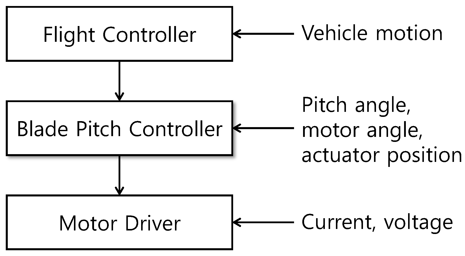
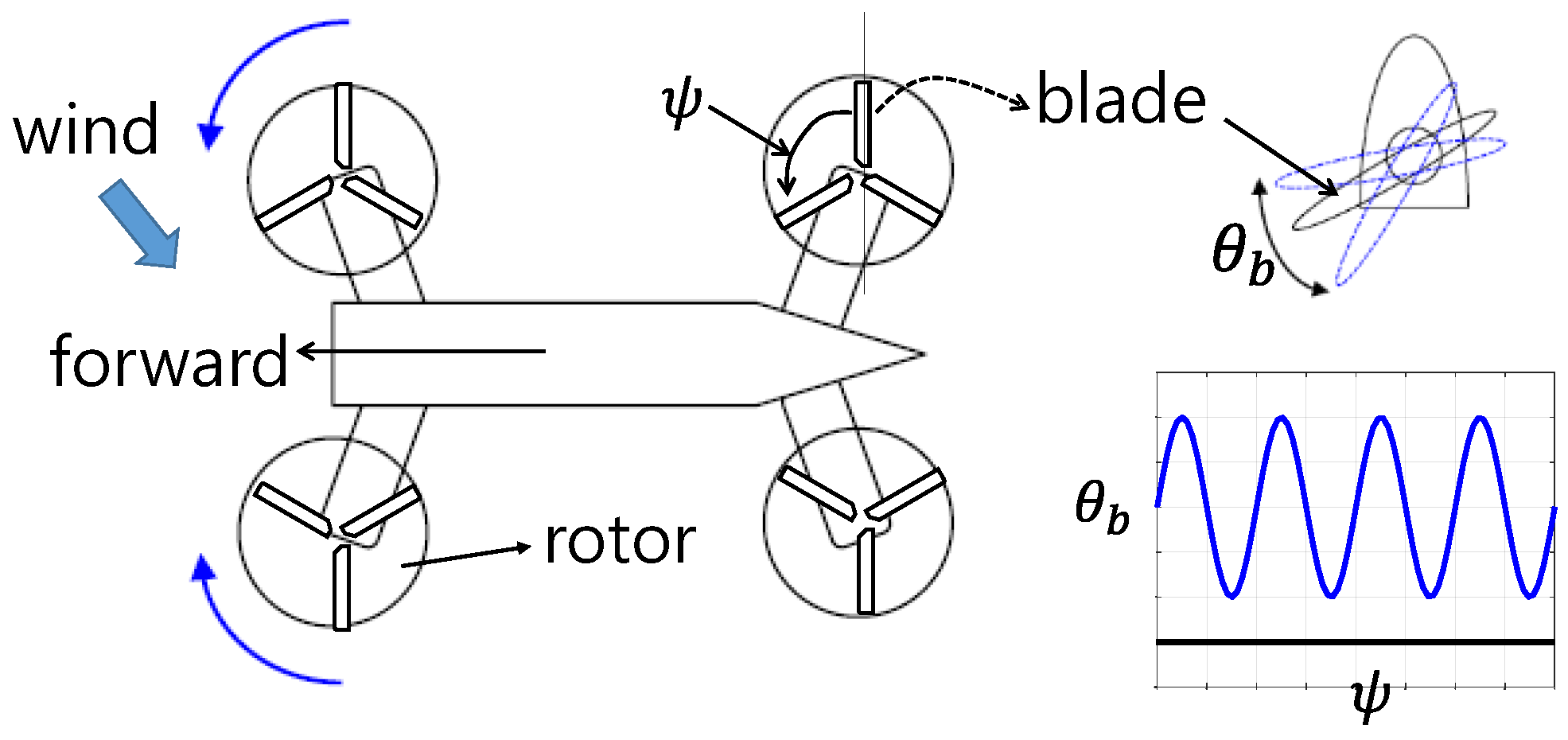
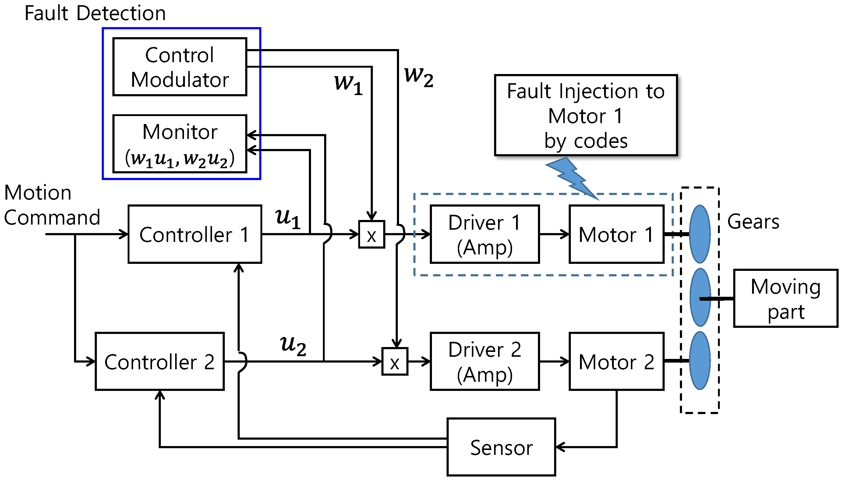
2. System Description and Problem Definition

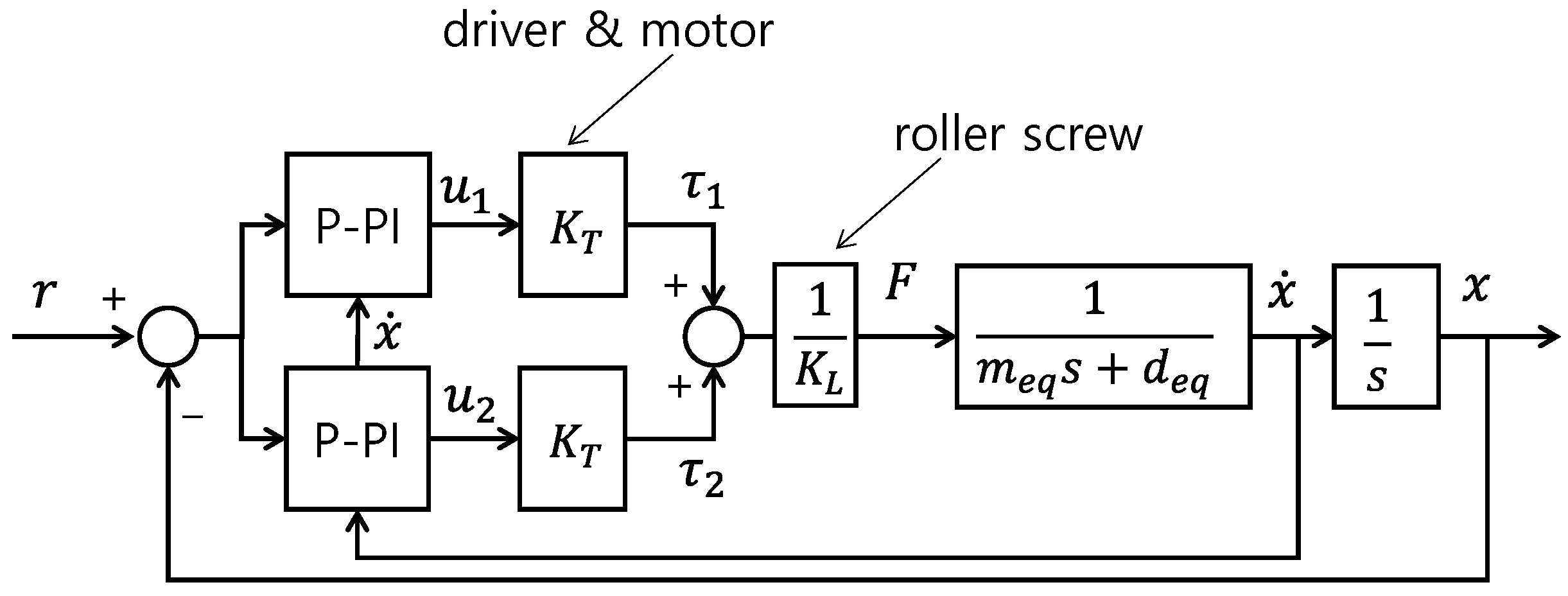
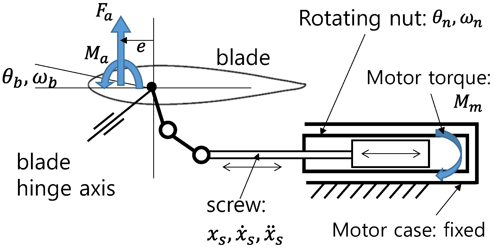
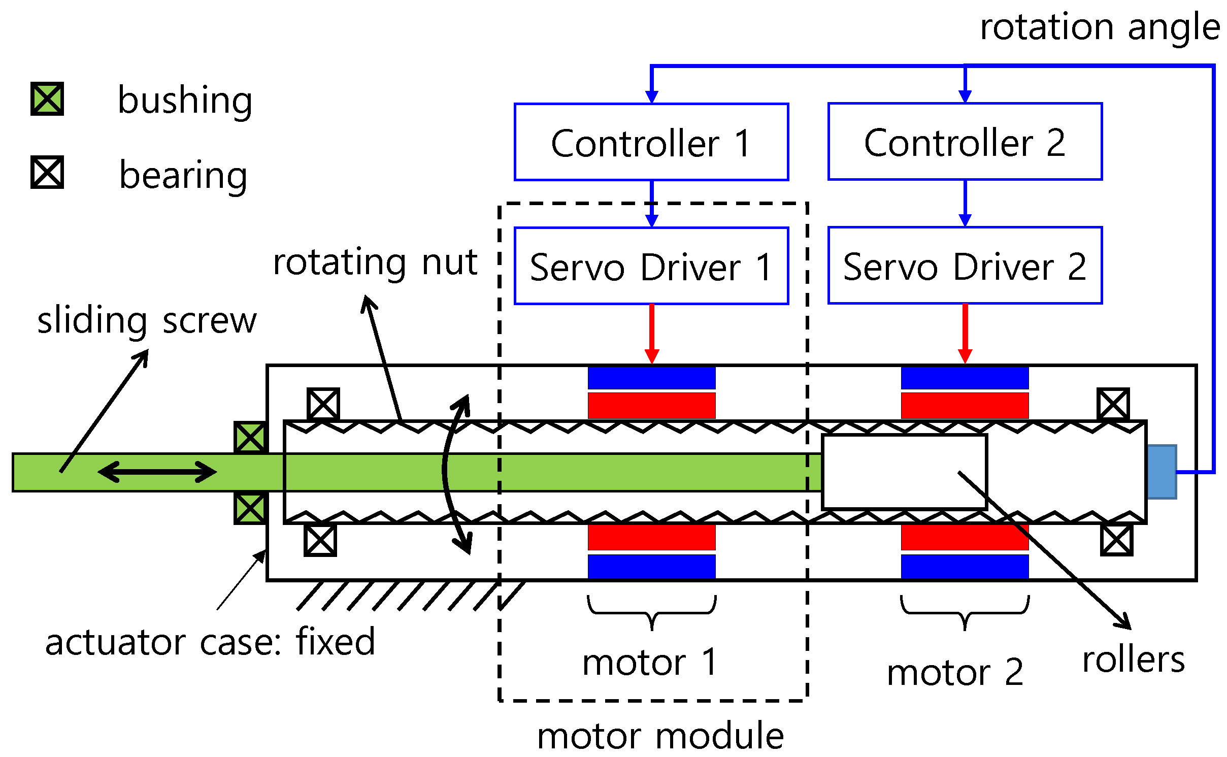
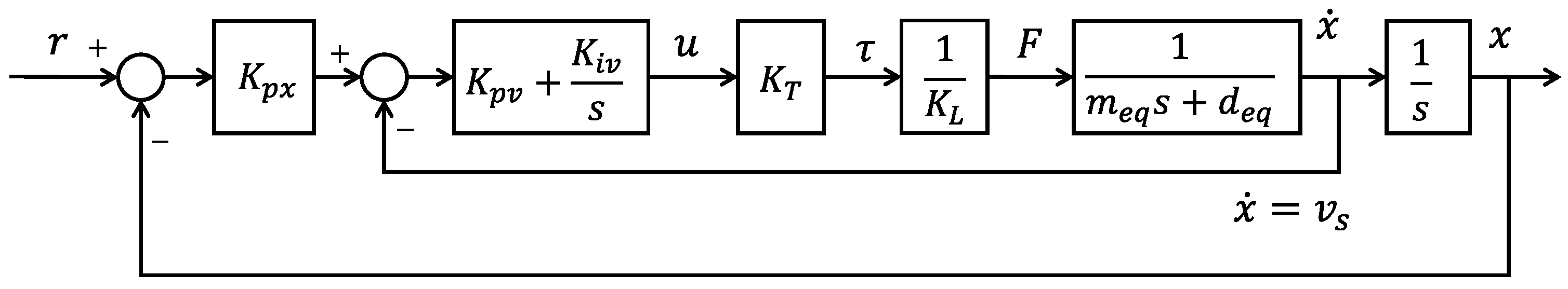
2.1. System Description

The target system is the individual blade control (IBC) system of UAM and is schematically shown in Figure 2 [24].
As the rotor blade rotates, its pitch angle ( θ b ) changes along its azimuth angle ( ψ ) to attenuate disturbances. A helicopter has a swashplate to adjust the pitch angle. However, the target UAM has no swashplate. Instead, an actuator individually controls the blade, as shown in Figure 3 [24]. This is the concept of the IBC.
The actuator in this study is based on the dual-type motor modules, as shown in Figure 4. The motor module consists of a controller, a servo driver, and magnetic apparatus (a motor in a narrow sense). A common sensor measures the rotation angles. The same measurements are used for calculating control signals. The motor modules rotate a nut, and the rotational motion of the nut is converted into the translational motion of the screw. This conversion mechanism is based on a roller screw [25].

2.2. Controller and Driver

The controller for the motor consists of two loops, a speed loop (inner loop), and a position loop (outer loop), as shown in Figure 5. The speed and position loops are based on a PI controller and a simple P controller, respectively (totally P-PI control). The driver dynamics is faster than the speed loop. Therefore, it is considered a simple constant ( K T ). u is the control signal that is the output of the controller and the input to the servo driver. K L is the torque-to-force conversion factor related to the lead of the roller screw.
Figure 6 shows the block diagram of the actuator of two motors in Figure 4.
The original blade dynamics is nonlinear because of the two-rod linkage (shown in Figure 3). However, because the range of the blade pitch angle is small, the dynamics is almost linear. Therefore, the equivalent mass ( m e q ) is assumed to be constant.
The P and PI gains are the same for both controllers, and both controllers use the same error signal. Therefore, the control signals, which are the outputs of both controllers, are assumed to be the same ( u 1 = u 2 ).

2.3. Problem Definition

The two controllers in Figure 6 use the same logic and gains as mentioned above. The problem is detecting a faulty part. Faults are assumed to occur in any part including drivers and magnetic elements. Although several fault modes are possible, it is sufficient to detect a faulty module.

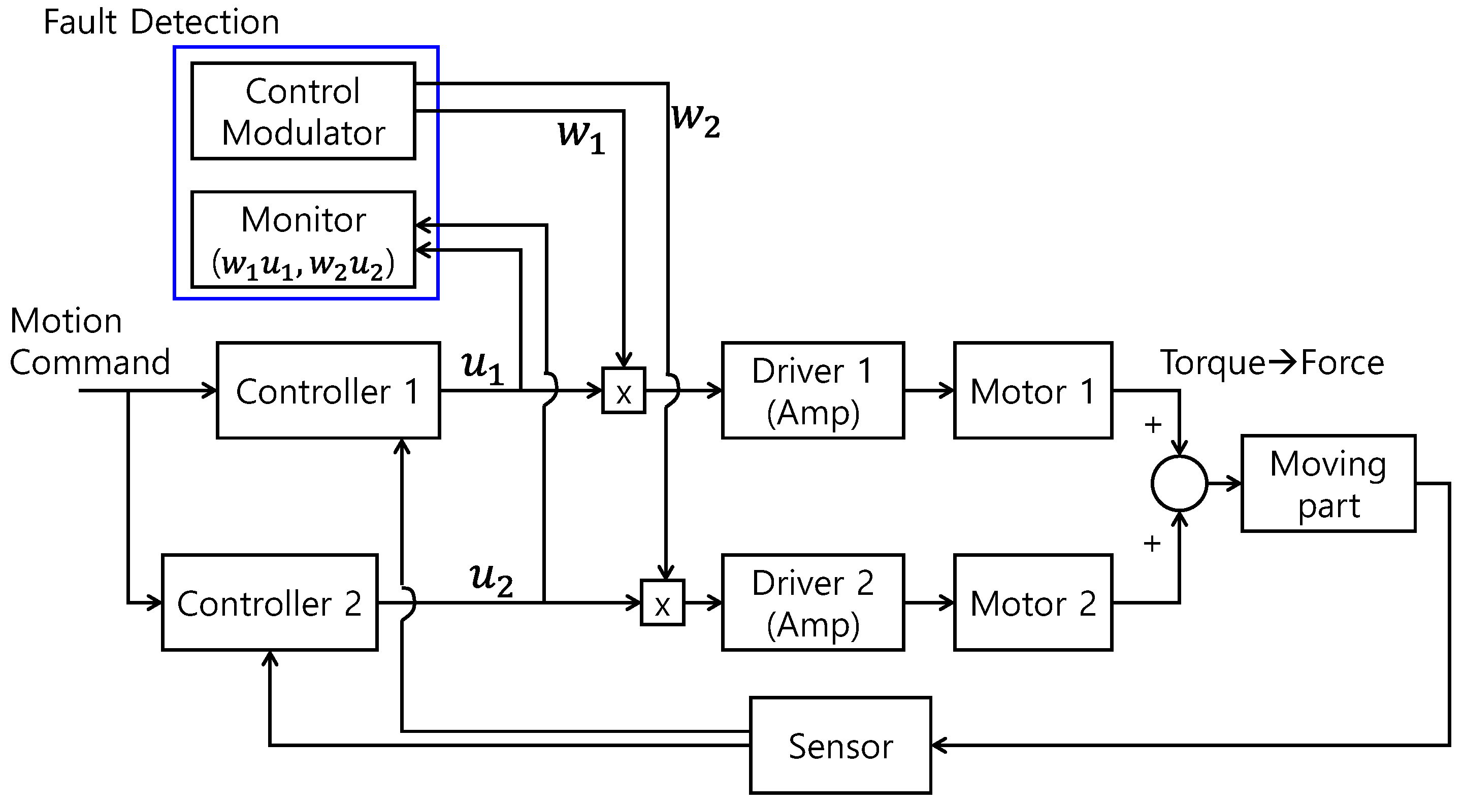
3. Proposed Fault Detection Method

3.1. Fault Modes

Three test fault modes are considered: The motor output torque is (1) zero, (2) fixed at a constant value, and (3) scaled-down. Then, the mathematical expressions for motor torques are given as:
τ = { 0 c o n s t a n t α K T u , 0 < α < 1
The scaled-down mode models the aging effect. These modes are considered in the following simulation studies.

3.2. Proposed Method

The proposed method is shown in Figure 7. In this approach, the control signals ( u 1 and u 2 ) are modulated by w 1 and w 2 that are generated by the modulator, and these modulated control signals ( w 1 u 1 and w 2 u 2 ) are monitored and compared.
The weighting factors w 1 and w 2 satisfy the following conditions.
w 1 ( t ) = 1 + δ ( t ) , w 2 ( t ) = 1 δ ( t )
where δ ( t ) is a periodic function of the period T ( δ ( t ) = δ ( t + T ) ), and its amplitude is limited as 1 < δ ( t ) < 1 . A sinusoidal wave and a triangular wave, shown in Figure 8, are good examples for w 1 and w 2 .
If w 1 > w 2 , Motor 1 has to generate a larger torque than Motor 2. This modulation causes the faulty motor to respond differently compared with the healthy one. We show this difference through simulations and explain the underlying physical mechanism in the following sections.

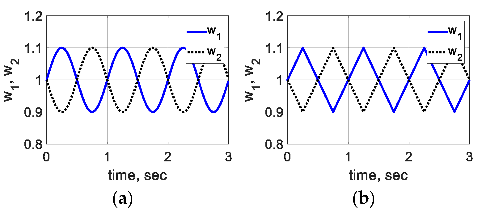
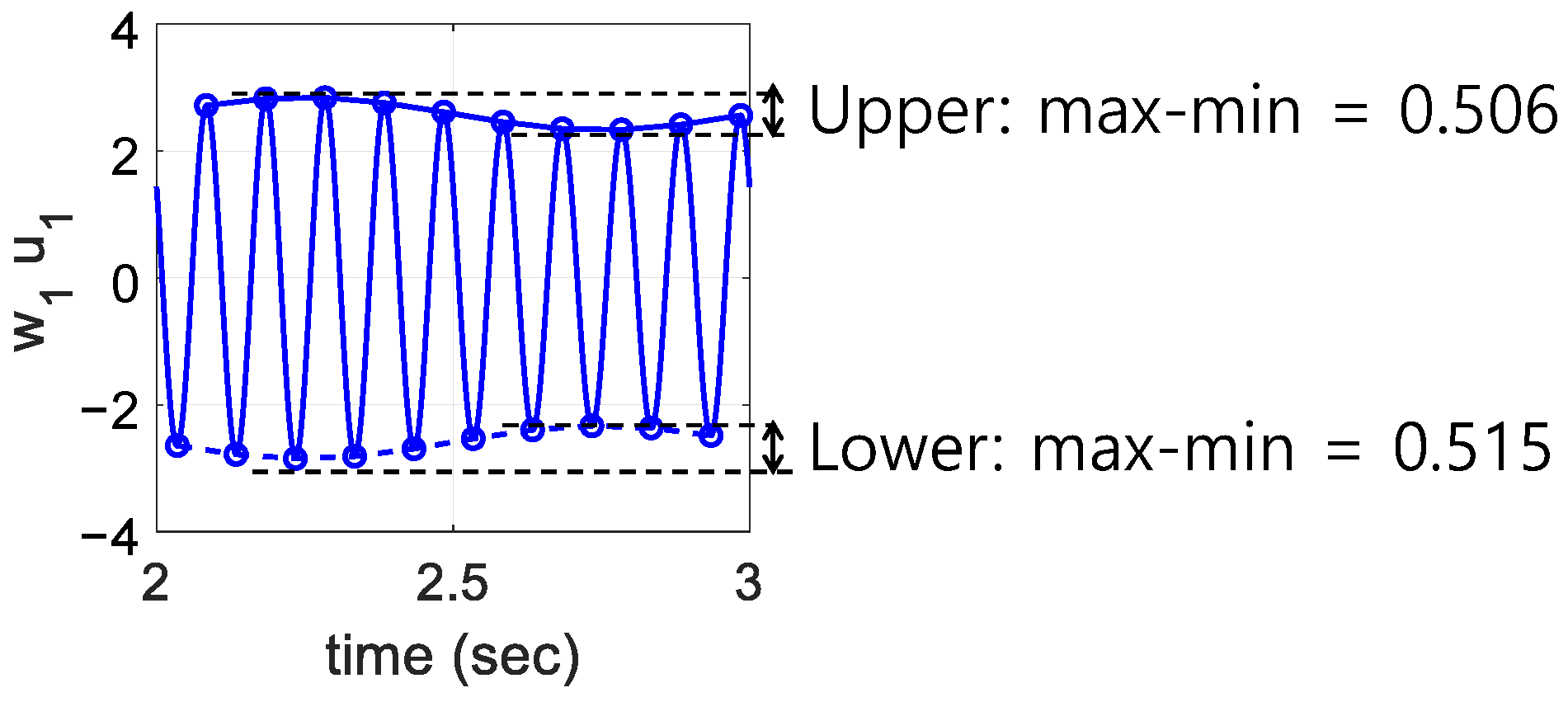
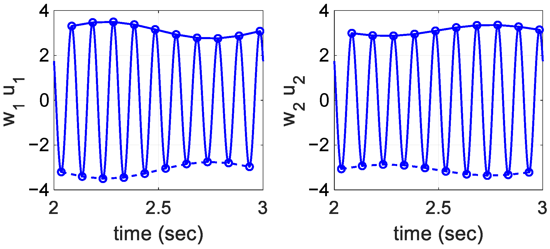
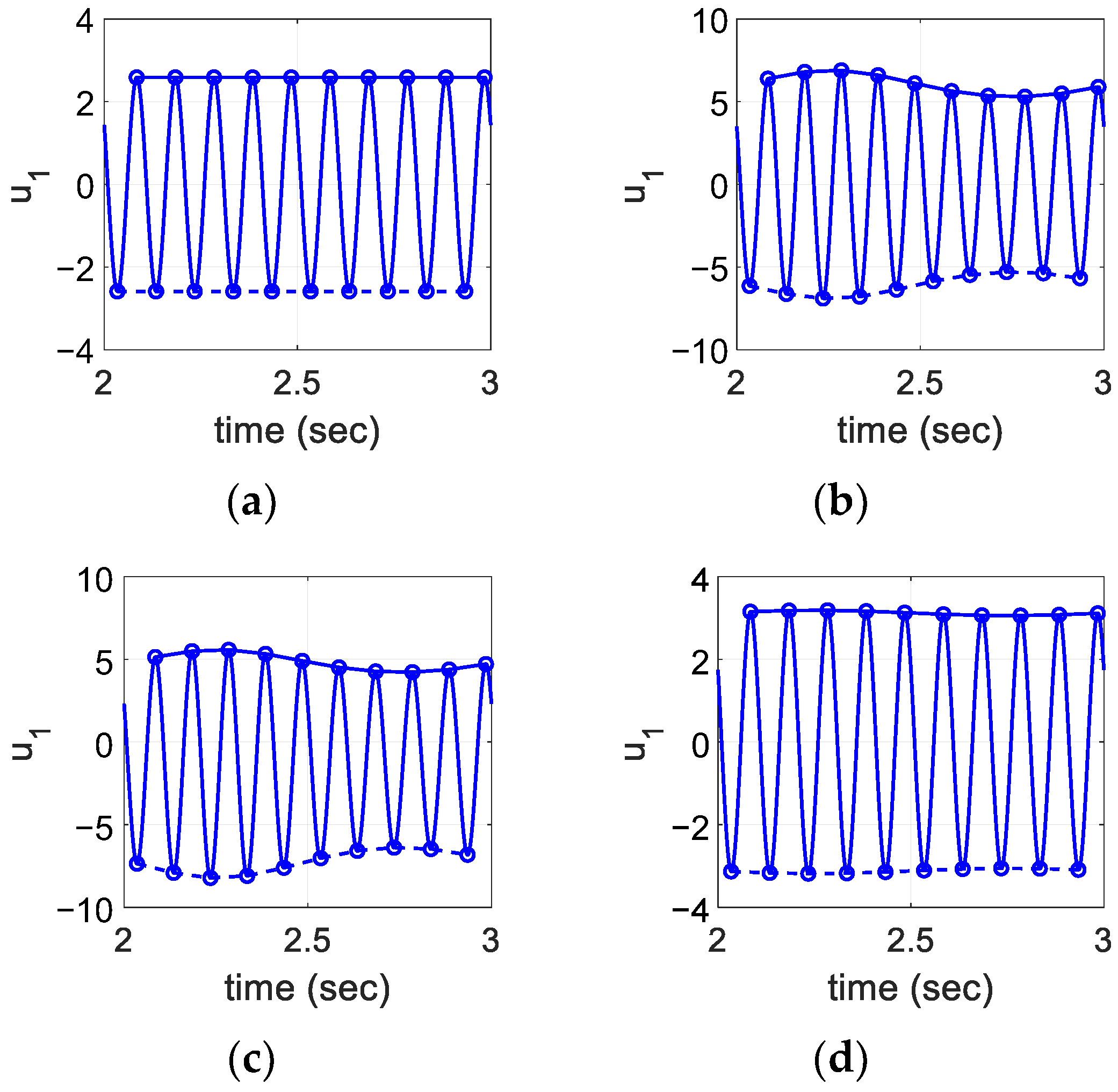
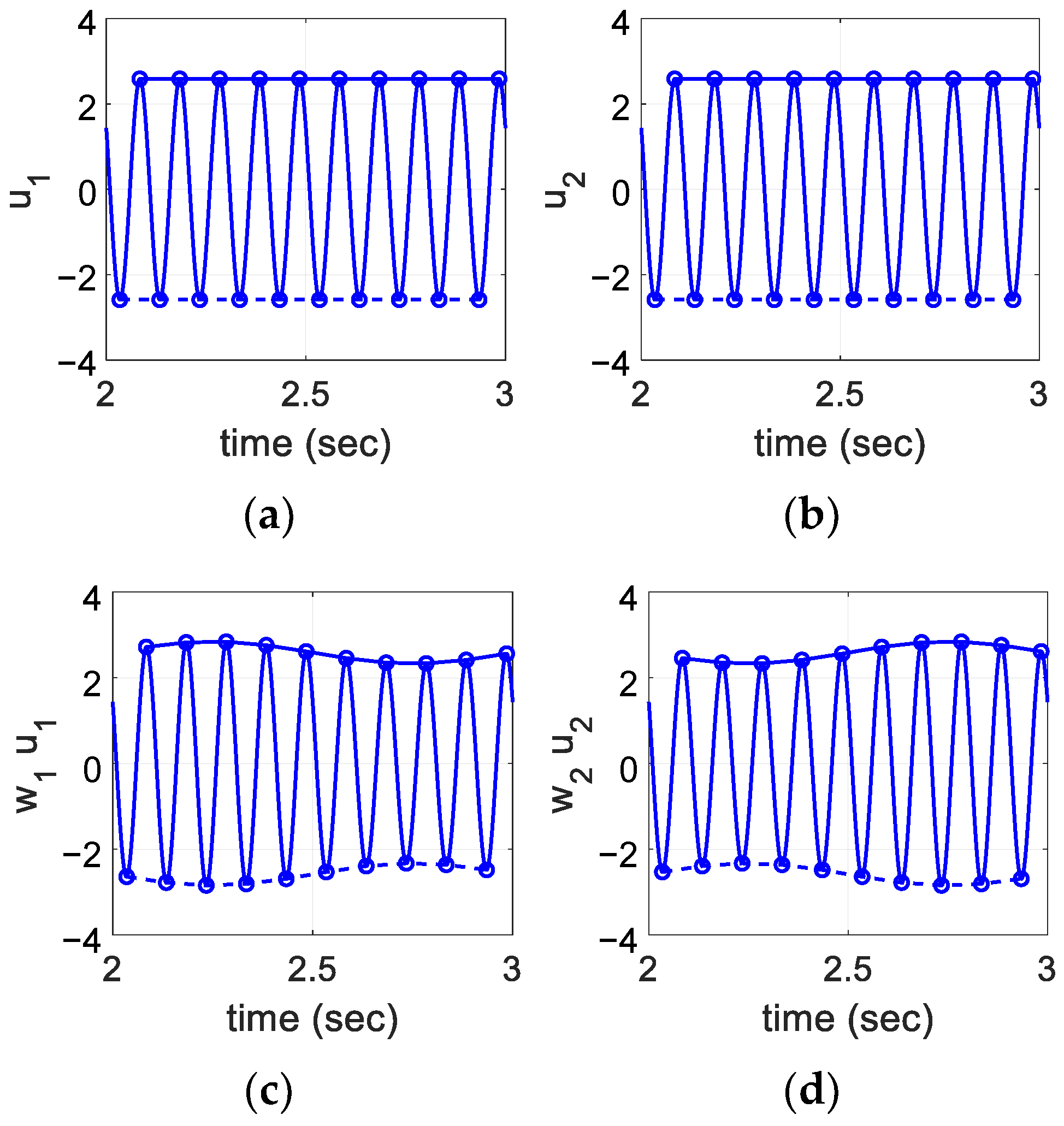
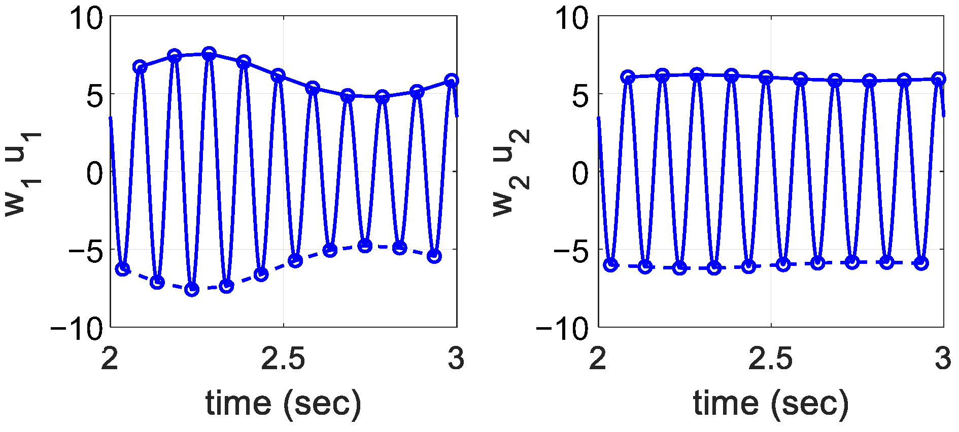
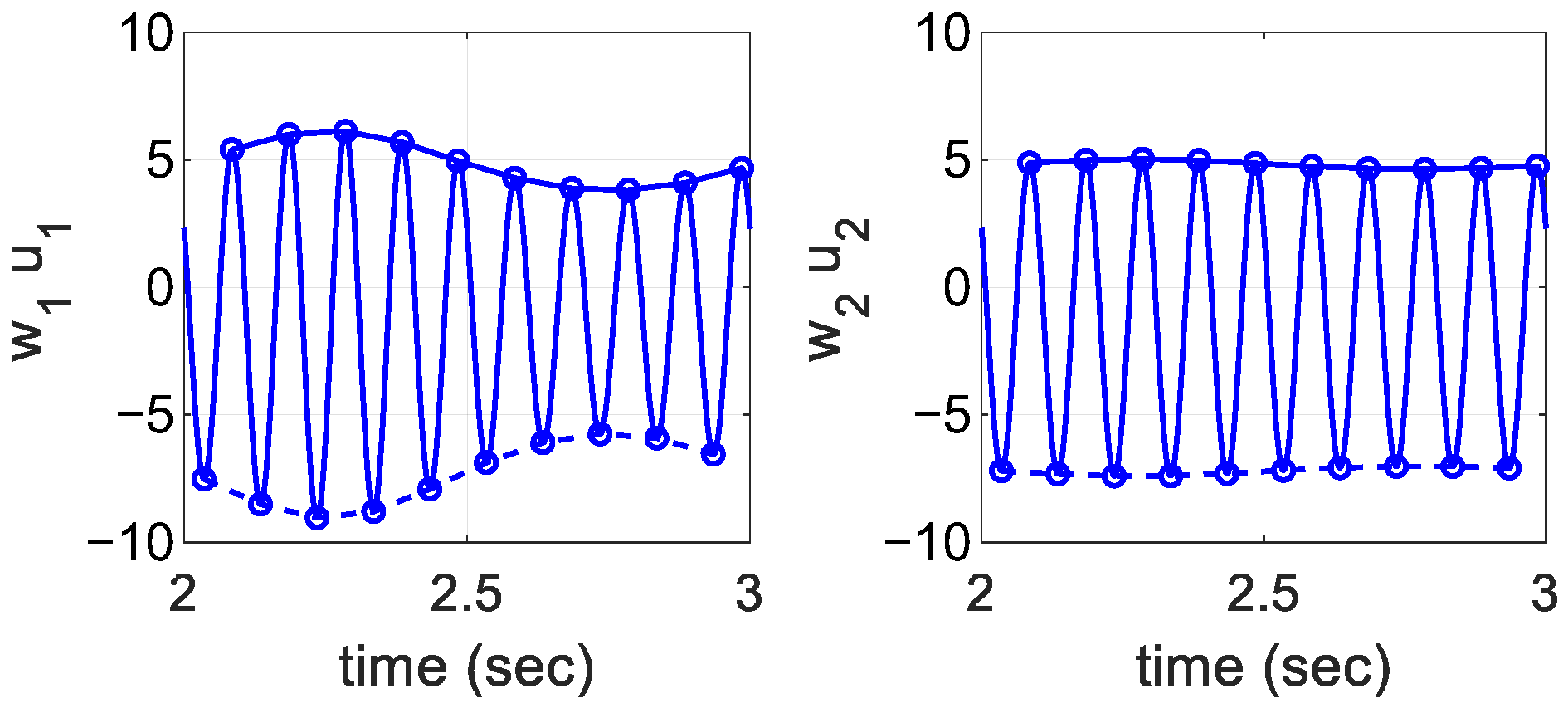
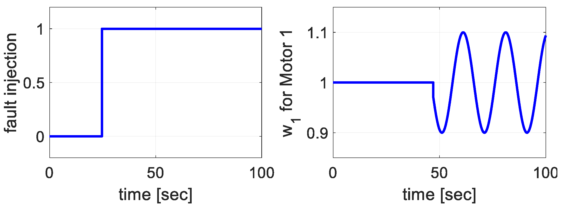
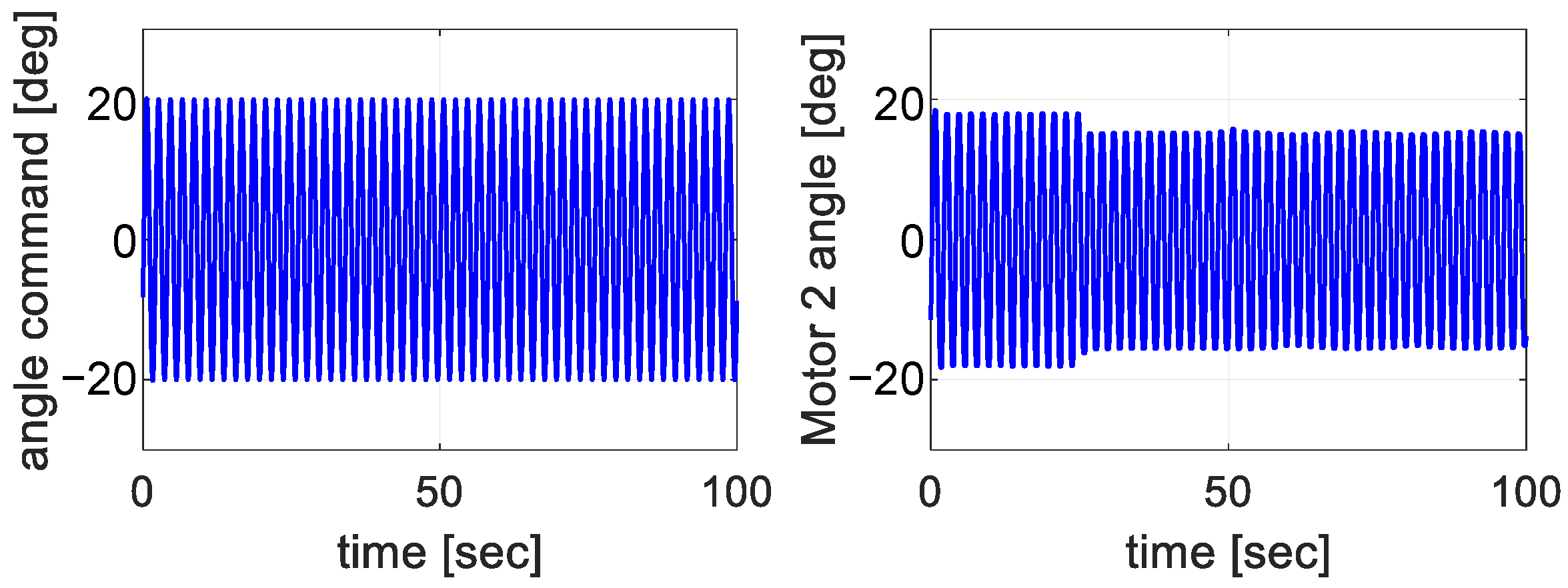
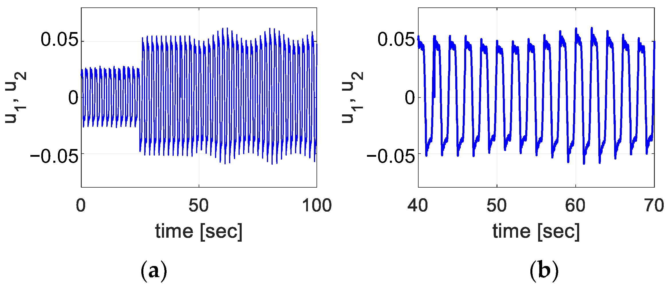
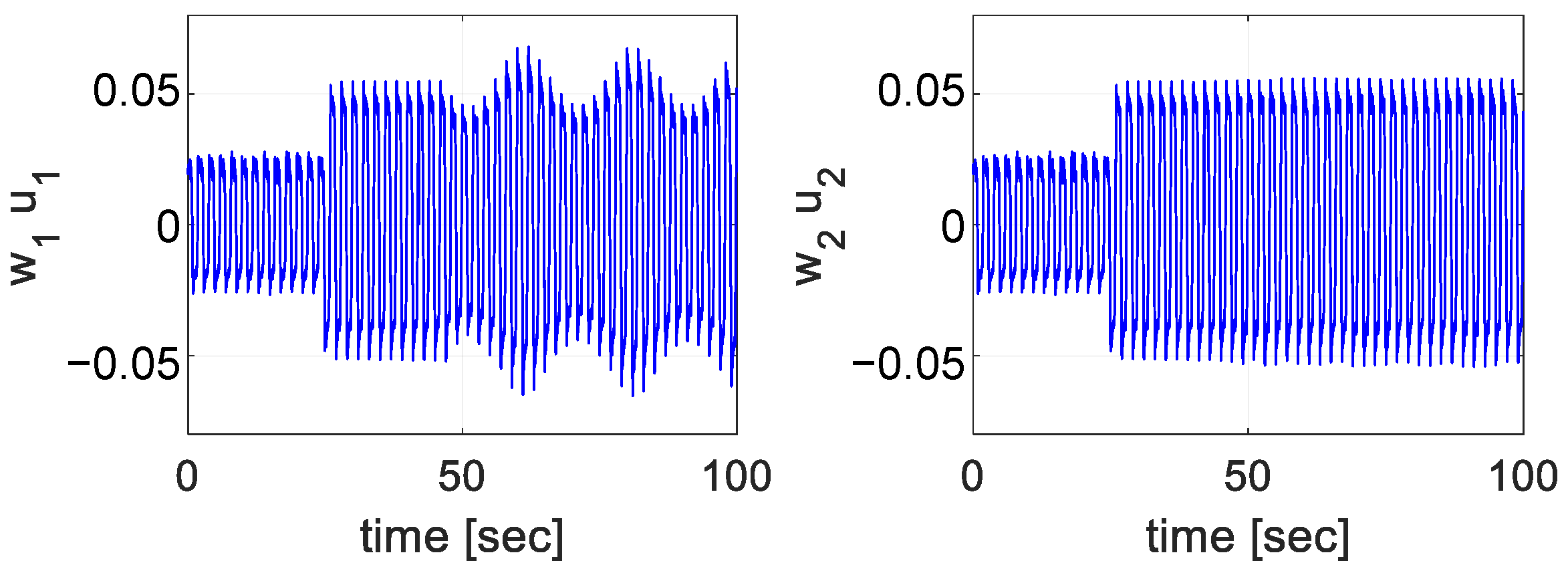
3.3. Simulation Studies

The parameters in Figure 5 are listed in Table 1. The PI gains of the inner loop are chosen by the following equations [26], where the design parameter ω c s is the desired inner loop bandwidth, and K p x is chosen to design the appropriate outer loop.
K p v = m e q ω c s K T K L ,     K i v = m e q ω c s 2 5 K T K L
The motion command is
r ( t ) = 5 sin ( 2 π f t ) [ mm ] ,     f = 10   [ hz ]
The frequency of the modulating signals w 1 and w 2 must be smaller than the period of the motion command as:
δ ( t ) = 0.1 sin ( 2 π f d t ) ,     f d = 1   [ hz ]
Figure 9 shows the control signals and modulated signals when both motors are normal. The control signals are the same because the controller gains and input error signals are the same. The modulated signals vary as δ ( t ) . Envelope variations are monitored.
As an example, and as shown in Figure 10, the positive (or upper) and negative (or lower) peaks (empty circles) of w 1 u 1 are analyzed, and the differences between the maximum and the minimum values are calculated. We define this as a pattern variation. Pattern variations are recorded for w 1 u 1 (A in Table 2) and for w 2 u 2 (B in Table 2). In the table, U denotes the pattern variation calculated by using the upper peaks, and L denotes the pattern variation of the lower peaks.
Figure 11, Figure 12 and Figure 13 show the modulated control signals ( w 1 u 1 ,   w 2 u 2 ) when Motor 1 is faulty.
The results are summarized in Table 2, and the difference (C = |A − B|) and the ratios (D = A/B) are compared. The pattern variations of a faulty motor are greater than that of a healthy motor (C > 0 or D > 1). Both indicators (C, D) work well for all cases. For the zero output and fixed output fault modes, the values (C, D) are much greater than the values of the normal case. This means that the greater the pattern variations are, the more severe the fault levels are. For the zero output mode, the healthy motor’s pattern variation ( w 2 u 2 ) is smaller than in the normal case. For the fixed output mode, the modulated control signals are biased because of u 1 , u 2 , and the average of U and L is the proper index. For the scaled-down mode, the pattern variations depend on the degree of faults.
The fault detection algorithm is summarized as follows:
  • For C, if |A − B| exceeds a threshold, a fault has occurred. For D, if A/B or B/A is above a threshold, a fault has occurred.
  • For C, Motor 1 is faulty if A > B, and Motor 2 is faulty if otherwise. For D, Motor 1 is faulty if A/B > 1, and Motor 2 is faulty if otherwise.
Figure 14 shows the control signals, and Figure 15 shows the command and output positions for comparison. When a fault occurs, the control signals increase to overcome the loss of one motor. For the scaled-down mode, the power loss is not great (30% loss). Hence, the control performance does not degrade significantly.

3.4. Discussion

The modulated control signals change the behaviors of both motors. The larger the modulated signal (e.g., w 1 > 1 ), the more torque the corresponding motor must generate. A healthy motor can do this, but a faulty motor cannot. For example, if the fault mode is ‘zero output’, the faulty motor would not generate torque at all. Then, the position error would increase, and the controller would generate larger commands to compensate for the position error. For this reason, the behaviors of a normal motor and a faulty one are different, and the pattern variations of the modulated signals differ according to these behaviors. Generally, the pattern variation of the modulated signal of a faulty motor is larger than that of a healthy motor. By this mechanism, the proposed method can find a faulty motor with the three considered fault modes.

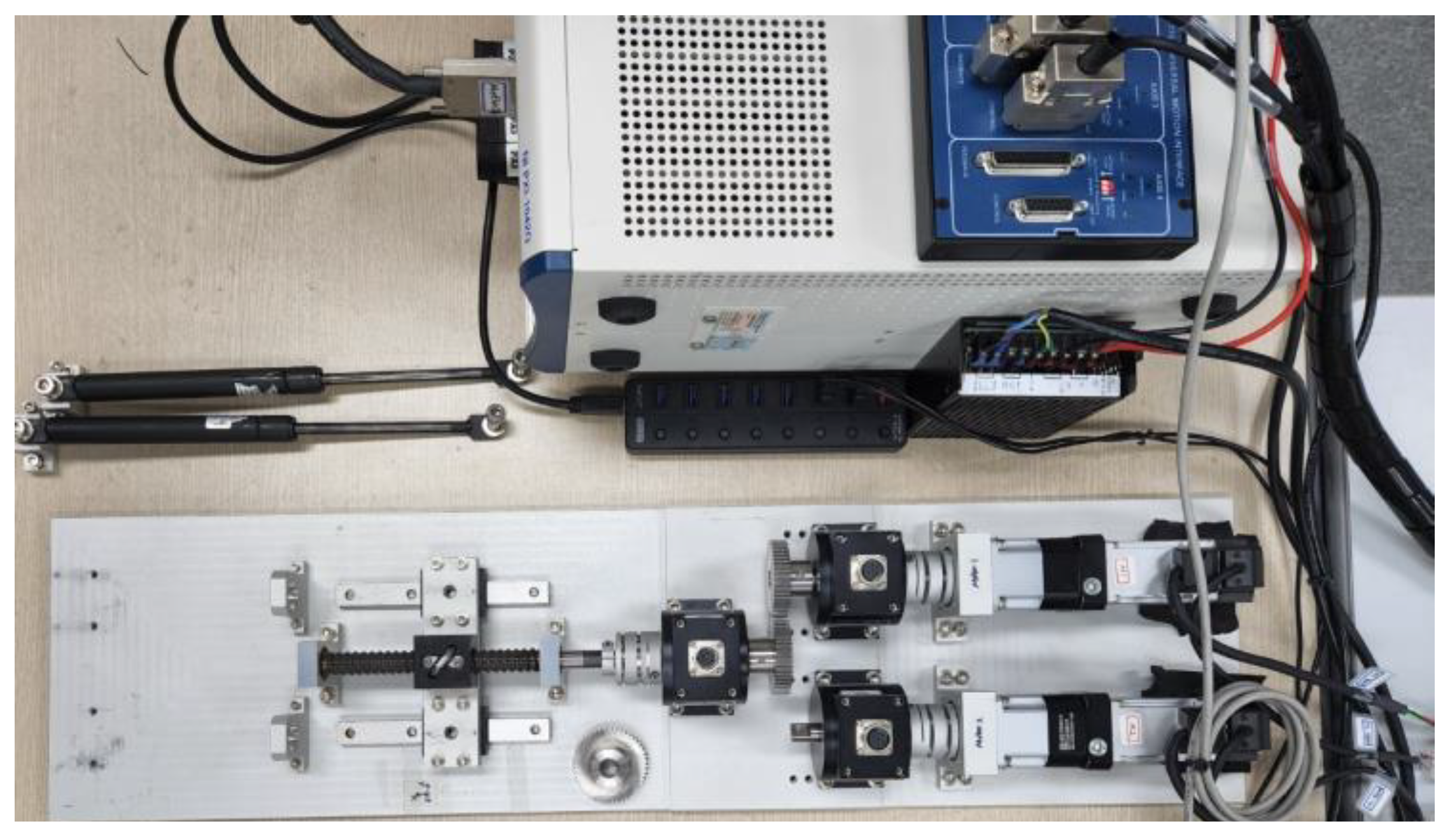
4. Experiments with Servo Motors

4.1. Test Equipment and Conditions
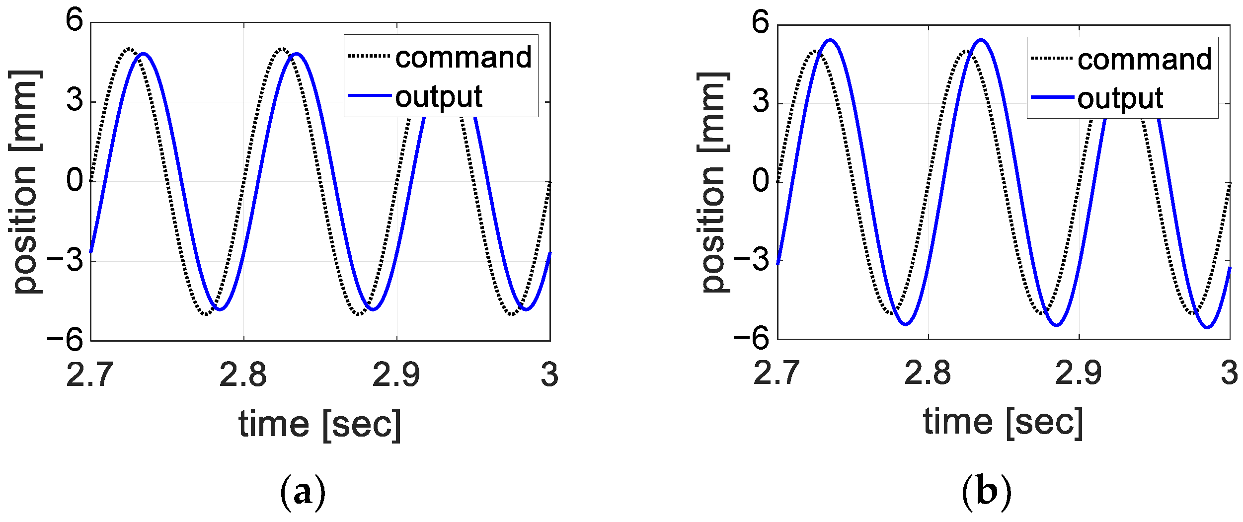
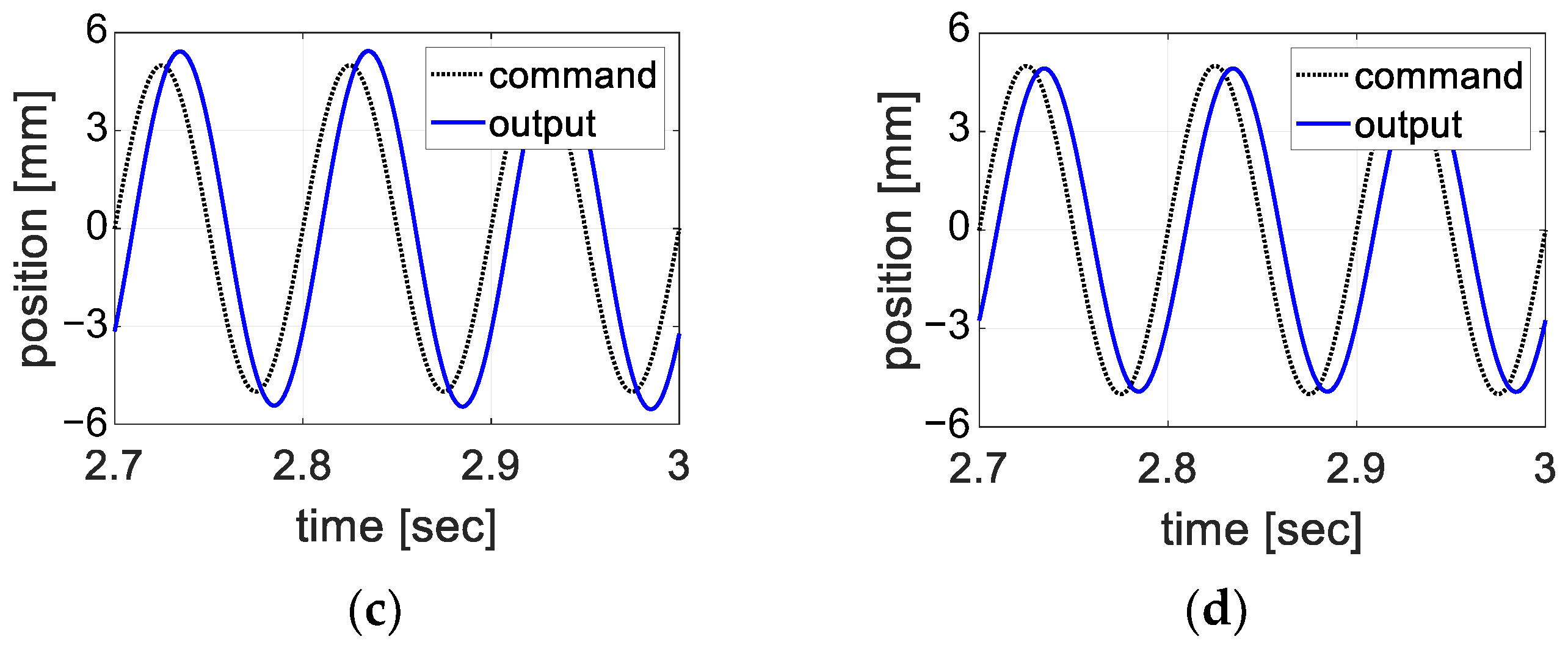
Since the actuator for the IBC in Figure 4 is not ready now, we have prepared a simple test bed using commercial servo motors and gears for testing the proposed fault detection method, as shown in Figure 16 and Figure 17. The servo motors are connected by spur gears, and Controller 1 and 2 use the encoder information of Motor 2. This connection has the same effect as a dual-type motor sharing a single axis, as shown in Figure 4 and Figure 7.
The prepared fault mode is only the zero output mode. The purpose of the test is to demonstrate the variations in the modulated signals.
We have chosen a faulty motor in advance and injected fault by codes. Motor 1 has been chosen. The healthy one (Motor 2) operates regardless of the other’s condition. Both use the healthy motor’s sensor (encoder). The translation part (ball screw) is disconnected just for safety. A conventional PID is used for Controller 1 and 2 instead of P-IP in Figure 5 just for simplicity. The gains are determined by tuning.

4.2. Test Results

Test results are presented in Figure 18, Figure 19, Figure 20 and Figure 21. In Figure 18, the zero output fault is injected at 24.6 s, and the modulation starts at 47.1 s.
Figure 19 shows the command and measured angles. The command angle is 20 sin ( 2 π × 0.5 t ) [deg]. During the normal period (0~24.6 s), the two motors work, and the obtained angle amplitude is about 18 degrees. This is due to the properties of the test servo motors (amplitude reduction and phase delay). When the fault is injected (>24.6 s), only one motor works and attempts to track the command angle. However, the other (faulty motor) becomes a burden on the healthy one, and the healthy one does not adequately accommodate this burden.
Figure 20 shows the control signals ( u 1 , u 2 ). When the modulation starts, the control signals also fluctuate slightly.
Figure 21 shows the modulated control signals ( w 1 u 1 , w 2 u 2 ). The pattern variations of w 1 u 1 are greater than those of w 2 u 2 , and this indicates that Motor 1 is faulty. Based on these differences, the faulty motor is identified.

4.3. Discussion

The proposed method is simple and uses only control signals instead of current signals. However, the detection time or period is longer than the period of the sinusoidal control signal or the rotation period of the blade. The rotational speed of the blade is estimated to be 200~600 rpm. If we wait 10 cycles for detection as simulation examples, then we need 1~3 s for detection. With a healthy motor, there would be no severe fault growth, and proper fault accommodation logic would work after diagnosis.

5. Conclusions

This paper deals with the problem of fault detection in redundant motors, applied to the blade pitch control of UAM. In particular, two redundant motors are dual-type and use a common sensor, such as an encoder. Because the structures of the controller for each motor are the same, the same control signals are generated regardless of faults. The author proposed a method of modulating control signals using time-varying weights for detecting a faulty motor. Simulations showed that a faulty motor is correctly determined for the three test fault modes, and experiments showed that the modulated control signals were different. In conclusion, the proposed method is useful for detecting a faulty motor and providing correct information for proper fault accommodation. The proposed method works without current signals that were generally used by previous studies. Hence, the proposed method can be alternative or complementary to the other methods using current signals.

Funding

This paper is the result of research conducted with the government (Ministry of Trade, Industry and Energy) funding and the support of the Korea Evaluation Institute of Industrial Technology in 2021 (No.20015907, High reliability, speed and output power, multiple electro-mechanical actuator development for eVTOL mobility).

Data Availability Statement

All data, models, or code that support the findings of this study are available from the corresponding author upon reasonable request.

Acknowledgments

The author appreciates the insightful comments and constructive suggestions of the editors and the anonymous reviewers.

Conflicts of Interest

The authors declare no conflict of interest.

References

  1. Zolghadri, A.; Henry, D.; Cieslak, J.; Efimov, D.; Goupil, P. Fault Diagnosis and Fault-Tolerant Control and Guidance for Aerospace Vehicles; Springer: London, UK, 2014; pp. 1–27. [Google Scholar]
  2. Monteriù, A.; Freddi, A.; Longhi, S. (Eds.) Fault Diagnosis and Fault-Tolerant Control of Robotic and Autonomous Systems; IET: London, UK, 2020. [Google Scholar]
  3. Huang, C.; Naghdy, F.; Du, H.; Huang, H. Fault tolerant steer-by-wire systems: An overview. Annu. Rev. Contr. 2019, 47, 98–111. [Google Scholar] [CrossRef]
  4. Zhang, W.; Yang, X.; Xu, Z.; Zhang, W.; Yang, L.; Liu, X. An adaptive fault-tolerant control method for robot manipulators. Int. J. Control. Autom. Syst. 2021, 19, 3983–3995. [Google Scholar] [CrossRef]
  5. Maré, J.; Fu, J. Review on signal-by-wire and power-by-wire actuation for more electric aircraft. Chin. J. Aeronaut. 2017, 30, 857–870. [Google Scholar] [CrossRef]
  6. Song, K.; Yeo, H.; Moon, J. Approach control concepts and optimal vertiport airspace design for urban air mobility (UAM) operation. Int. J. Aeronaut. Space Sci. 2021, 22, 982–994. [Google Scholar] [CrossRef]
  7. Jiang, X.; Wang, S.; Li, Q.; Gao, Y. Design and optimization of dual-winding fault-tolerant permanent magnet motor. CES Trans. Electr. Mach. Syst. 2019, 3, 45–53. [Google Scholar] [CrossRef]
  8. Jiang, X.; Huang, W.; Cao, R.; Hao, Z.; Jiang, W. Electric drive system of dual winding fault tolerant permanent magnet motor for aerospace applications. IEEE Trans. Ind. Electron. 2015, 62, 7322–7330. [Google Scholar] [CrossRef]
  9. Gao, Y.; Ma, J.; Chen, Q.; Wu, Y. Characteristic model-based adaptive fault tolerant control for four motor synchronization systems considering actuator failure. Int. J. Control. Autom. Syst. 2021, 19, 4010–4024. [Google Scholar] [CrossRef]
  10. Ferdowsi, H.; Cai, J.; Jagannathan, S. Actuator and sensor fault detection and failure prediction for systems with multi-dimensional nonlinear partial differential equations. Int. J. Control. Autom. Syst. 2022, 20, 789–802. [Google Scholar] [CrossRef]
  11. Xu, Q.; Lee, K.-M.; Zhou, H.; Yang, H.-Y. Model-based fault detection and isolation scheme for a rudder servo system. IEEE Trans. Ind. Electron. 2015, 62, 2384–2396. [Google Scholar] [CrossRef]
  12. Park, B.; Park, B.G.; Kim, T.S.; Ryu, J.S.; Lee, B.K.; Hyun, D.S. Fault tolerant system under open phase fault for BLDC motor drives. In Proceedings of the 2006 37th IEEE Power Electronics Specialists Conference, Jeju, Korea, 18–22 June 2006; pp. 1–6. [Google Scholar]
  13. Aqil, M.; Hur, J. Multiple sensor fault detection algorithm for fault tolerant control of BLDC motor. Electronics 2021, 10, 1038. [Google Scholar] [CrossRef]
  14. Kim, Y.; Bae, H.; Kim, S.; Vachtsevanos, G. Fault diagnosis of ac servo motor with current signals based on wavelet decomposition and template matching methods. In Proceedings of the 17th World Congress IFAC, Seoul, Korea, 6–11 July 2008; pp. 7239–7244. [Google Scholar]
  15. Purbowaskito, W.; Wu, P.; Lan, C. Permanent magnet synchronous motor driving mechanical transmission fault detection and identification: A model-based diagnosis approach. Electronics 2022, 11, 1356. [Google Scholar] [CrossRef]
  16. He, L.; Chen, G.Y.; Zheng, H.Y. Fault tolerant control method of dual steering actuator motors for steer-by-wire system. Int. J. Automot. Technol. 2015, 16, 977–987. [Google Scholar] [CrossRef]
  17. Zou, Y.; Zhang, Y.; Mao, H. Fault diagnosis on the bearing of traction motor in high-speed trains based on deep learning. Alex. Eng. J. 2021, 60, 1209–1219. [Google Scholar] [CrossRef]
  18. Zhao, H.; Liu, J.; Chen, H.; Chen, J.; Li, Y.; Xu, J.; Deng, W. Intelligent diagnosis using continuous wavelet transform and gauss convolutional deep belief network. IEEE Trans. Reliab. 2022, 1–11. [Google Scholar] [CrossRef]
  19. Zhaoyang, F.; Jinglin, L. Fault diagnosis of dual-redundancy BLDC motor. In Proceedings of the 2015 18th International Conference on Electrical Machines and Systems, Pattaya, Thailand, 25–28 October 2015; pp. 1209–1213. [Google Scholar]
  20. Guo, F.; Ren, X.; Li, Z.; Han, C. Kalman filter based fault detection of dual motor systems. In Proceedings of the 36th Chinese Control Conference, Dalian, China, 26–28 July 2017. [Google Scholar]
  21. Jiang, X.; Huang, W.; Cao, R.; Zhu, P.; Jiang, W. Open-circuit fault diagnosis of a dual-winding fault-tolerant permanent magnet motor drive for aerospace applications. In Proceedings of the 2015 18th International Conference on Electrical Machines and Systems, Pattaya, Thailand, 25–28 October 2015; pp. 1204–1208. [Google Scholar]
  22. Noh, Y.; Kim, W.; Lee, J. The optimal current ratio control of redundant electric drive systems and diagnostic strategies for disagreement. IEEE Access 2021, 9, 32115–32130. [Google Scholar] [CrossRef]
  23. Kim, Y.; Heo, H.; Park, J.; Kim, J. Fault tolerant control methods for dual type independent multi-phase bldc motor under the open-switch fault conditions. J. Electr. Eng. Technol. 2018, 13, 722–732. [Google Scholar]
  24. Jin, J. Dynamic models of blade pitch control system driven by electro-mechanical actuator. J. Korean Soc. Aeronaut. Space Sci. 2022, 50, 111–118. [Google Scholar]
  25. Available online: https://en.wikipedia.org/wiki/Roller_screw (accessed on 1 October 2022).
  26. Kim, S. Electric Motor Control—DC, AC, and BLDC Motors; Elsevier Science: Amsterdam, The Netherlands, 2017. [Google Scholar]
Figure 1. Hierarchical fault detection and tolerance system.
Electronics 11 03338 g001
Figure 2. UAM, its rotors, and blade pitch control.
Electronics 11 03338 g002
Figure 3. Blade pitch angle controlled by a linear actuator.
Electronics 11 03338 g003
Figure 4. Linear actuator based on dual-type motors.
Electronics 11 03338 g004
Figure 5. Block diagram of the actuator position control by the torque control.
Electronics 11 03338 g005
Figure 6. Block diagram of the actuator position control by two motors.
Electronics 11 03338 g006
Figure 7. Proposed fault detection method for two motors.
Electronics 11 03338 g007
Figure 8. Examples of periodic weights: (a) Sinusoidal wave, (b) triangular wave.
Electronics 11 03338 g008
Figure 9. Simulation results when both motors are normal: (a) u 1 , (b) u 2 , (c) w 1 u 1 , (d) w 2 u 2 .
Electronics 11 03338 g009
Figure 10. Pattern variations for the modulated control signal.
Electronics 11 03338 g010
Figure 11. Modulated control signals for the zero output fault mode.
Electronics 11 03338 g011
Figure 12. Modulated control signal for the fixed output fault mode (+500).
Electronics 11 03338 g012
Figure 13. Modulated control signal for the scaled-down fault mode (α = 0.7).
Electronics 11 03338 g013
Figure 14. Control signals ( u 1 ): (a) Normal, (b) the zero output mode, (c) the fixed output mode, (d) the scaled-down mode.
Electronics 11 03338 g014
Figure 15. Commands and outputs: (a) Normal, (b) the zero output mode, (c) the fixed output mode, (d) the scaled-down mode.
Electronics 11 03338 g015aElectronics 11 03338 g015b
Figure 16. Block diagram of the test bed with the gear mechanism.
Electronics 11 03338 g016
Figure 17. Photograph of the test bed.
Electronics 11 03338 g017
Figure 18. Signals for the fault injection (left) and time-varying weight w 1 (right).
Electronics 11 03338 g018
Figure 19. Command angle (left) and measured angle (right).
Electronics 11 03338 g019
Figure 20. Control signals ( u 1 , u 2 ): (a) t = 0~100 s, (b) t = 40~70 s.
Electronics 11 03338 g020
Figure 21. Modulated control signals: (left) w 1 u 1 , (right) w 2 u 2 .
Electronics 11 03338 g021
Table 1. Parameters for simulation studies.
ParametersValuesUnitParametersValuesUnit
m e q 114kg K p x 100-
d e q 11.4kg/s K p v 34.2-
ω c s 20 × 2 π rad/s K i v 859.5-
K T 1Nm/A K L 0.0024m
Table 2. Modulated control signals and pattern variations when Motor 1 is faulty.
CasesBoundary w 1 u 1
(A)
w 2 u 2
(B)
|A − B|
(C)
A/B
(D)
NormalU0.5060.50601.00
L0.5150.51501.00
(U + L)/20.5100.51001.00
Zero outputU2.7750.3932.387.06
L2.8080.3782.437.43
(U + L)/22.7910.3862.417.23
Fixed outputU2.3040.3931.915.86
L3.2880.3782.918.70
(U + L)/22.7960.3862.417.24
Scaled -downU0.7360.4840.251.52
L0.7480.4940.251.51
(U + L)/20.7420.4890.251.52
Publisher’s Note: MDPI stays neutral with regard to jurisdictional claims in published maps and institutional affiliations.

