Article

Scalable Hardware Efficient Architecture for Parallel FIR Filters with Symmetric Coefficients

1
NVIDIA Semiconductor Technology (Shanghai) Co., Ltd., Shanghai 200001, China
2
Faculty of Science and Engineering, Waseda University, Tokyo 169-8555, Japan
*
Author to whom correspondence should be addressed.
Electronics 2022, 11(20), 3272; https://doi.org/10.3390/electronics11203272
Submission received: 31 August 2022 / Revised: 8 October 2022 / Accepted: 9 October 2022 / Published: 11 October 2022
(This article belongs to the Special Issue FPGAs Based Hardware Design)

Abstract

:
Symmetric convolutions can be utilized for potential hardware resource reduction. However, they have not been realized in state-of-the-art transposed block FIR designs. Therefore, we explore the feasibility of symmetric convolution in transposed parallel FIRs and propose a scalable hardware efficient parallel architecture. The proposed design inserts delay elements after multipliers for temporal reuse of intermediate tap products. By doing this, the number of required multipliers can be reduced by half. As a result, we can achieve up to 3.2× and 1.64× area efficiency improvements over the modern transposed block method on reconfigurable and fixed designs, respectively. These results confirm the effectiveness of the proposed STB-FIR architecture for hardware-efficient, high-speed signal processing.

1. Introduction

Finite impulse response (FIR) filter, one primary digital filter, has been widely used in signal processing due to its stability and linear phase characteristics. With the time domain input, x n , and the filter coefficient, h m , the corresponding output, y n , of a T -tap FIR can be obtained as y n = m = 0 T 1 h m · x n m , according to the discrete time convolution [1]. Due to the accuracy requirement in frequency domain, T is generally large [2] and consequently, incurs a large silicon area with significant power consumption. Therefore, over the past decades, much research effort has been toward hardware efficient FIR filter implementations.
Because multipliers are generally more expensive than adders in terms of area and power consumption, many previous works have focused on the design of FIR filters with area-efficient multipliers. In some application-specific FIRs, the coefficients can be pre-determined; thus, instead of using the costly general multipliers, several constant-multiplier-based designs (CM) have been proposed [3,4,5,6,7,8]. These CM-based FIRs, however, are application-specific and only work for a specific coefficient set; therefore, they are not suitable in reconfigurable systems with programmable coefficients for real-time applications, such as adaptive pulse shaping and signal equalization [9]. On the other hand, because FIR filters are widely used in high-throughput multimedia signal processing and cellular wireless communication systems, there are also several parallel FIR implementations, such as fast FIR algorithm (FFA) [10,11,12] and block FIRs [13,14,15]. The basic idea of FFA is to break up an FIR filter into several sub-filters using polyphase decomposition so that they can operate in parallel with reduced computation complexity. In an FFA-based FIR filter design, the required number of multipliers can be greatly reduced at the cost of an increase in adders for extra pre-processing and post-processing. Symmetric FFA-based designs have also been proposed in [11,12] with the consideration of symmetric convolutions. Although FFA-based methods can achieve a significant reduction in multipliers, they are only effective for parallel FIR filters with low parallelism. Otherwise, the increased adders will introduce significant area overhead with the increased design complexity. On the other hand, block FIRs have also been proposed in [13,14,15] for high-throughput signal processing. Unlike FFA-based designs, block FIRs can be combined with CM-based methods for a specific coefficient set; however, the corresponding hardware resource increases linearly with the degree of parallelism. Therefore, area and power efficiency of the existing parallel FIRs are still the design challenges.
The symmetry of coefficients, which can lead to a significant saving in hardware cost, has not been taken into consideration in the existing block FIR designs yet. Therefore, we explore the feasibility of symmetric convolution in transposed parallel FIRs and propose a symmetric transposed block FIR filter (STB-FIR) architecture for area/power-efficient implementation of block FIR filters in which delay elements are inserted after multipliers for temporal reuse of intermediate tap products.
The remainder of this paper is organized as follows. The proposed STB-FIR architecture is illustrated in Section 2 with the corresponding generalized formulation. Evaluation results are provided in Section 3. Finally, the conclusion is given in Section 4.

2. Proposed STB-FIR

A T-tap digital FIR filter can be generally implemented either in the direct form or in the transposed form, as shown in Figure 1.

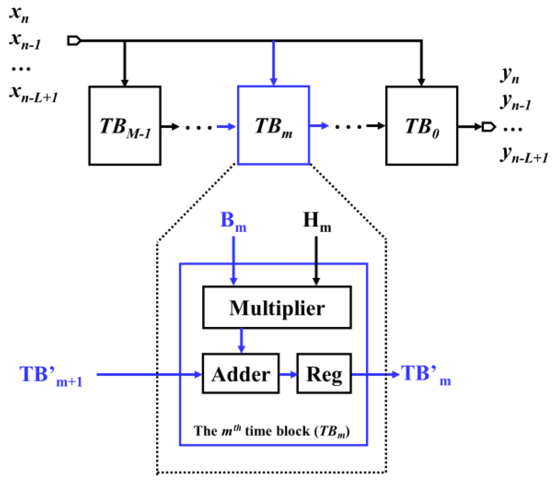
2.1. Generalized Mathematical Formulation for TB-Based FIRs

For L-parallel processing, the transposed block FIR proposed in [15] takes a block of L new input samples x n ,   x n 1 , , x n L + 1 and produces a block of L output samples y n ,   y n 1 , , y n L + 1 in each clock cycle. For a T -tap L -parallel transposed block FIR with T = M L and L and M indicate the degree of processing parallelism and the total number of blocks, respectively, the operations can be expressed in matrix form as:
y n y n 1 y n L + 1 = x n x n L + 1 x n 1 x n L x n j x n j L + 1 x n L + 1 x n 2 L + 2 x n L x n 2 L + 1 x n L 1 x n 2 L x n j L x n j 2 L + 1 x n 2 L + 1 x n 3 L + 2 x n M L + 1 x n M L x n j M L + 1 x n M + 1 L + 2 · h 0 h 1 h L 1 h M L 1
where x n ,   x n 1 ,   ,   x n L + 1 is the input of the current clock cycle, x n L ,   x n L 1 ,   ,   x n 2 L + 1 represents the input in the previous clock cycle, and { x n m L ,   x n m L 1 ,   ,   x n m + 1 L + 1 } represents the input m clocks before. It is obvious that the output of an FIR is a linear combination of the current input and some previous values.
According to (1), as an L -parallel FIR has L new inputs in each cycle, we define B m as
B m x n m L x n m L 1 x n m + 1 L + 1 x n m L j x n m L j + 1 x n m + 1 L j 1 x n m + 1 L + 1 x n m + 1 L x n m + 2 L + 2
Hence, substituting it into (1), we can obtain
y n y n 1 y n L + 1 = B 0 B 1 B m B M 1 · h 0 h 1 h M L 1  
Similarly, the coefficients can also be divided into M blocks as
H = h 0 h 1 h M L 1 H 0 H 1 H M 1   where   H m = h m L h m L + 1 h m + 1 L 1    
Thus, (3) can be further rewritten as
y n y n j y n L + 1 = B 0 B 1 B m B M 1 · H 0 H m H M 1 = B 0 · H 0 + B 1 · H 1 + + B M 1 · H M 1 = m = 0 M 1 B m · H m
Here, let the calculation of B m · H m be T B m , called time block in the following.
T B m B m · H m = x n m L x n m L 1 x n m + 1 L + 1 x n m L j x n m L j + 1 x n m + 1 L j 1 x n m + 1 L + 1 x n m + 1 L x n m + 2 L + 2 · h m L h m L + 1 h m + 1 L 1
According to (5), a TB-based scalable FIR architecture can be implemented in a transposed form, as shown in Figure 2, where a T -tap L -parallel block FIR filter has M ( =   T / L ) time blocks and can process M L input samples in M clock cycles with all the TBs working simultaneously. It should be noted that the input samples B m contains the current input and the previous input. Moreover, each time block ( T B m ) has the corresponding coefficients, H m , and the result is added to the output of the neighboring time block ( T B m + 1 ) to generate the output of T B m and then is sent to the next time block ( T B m 1 ).

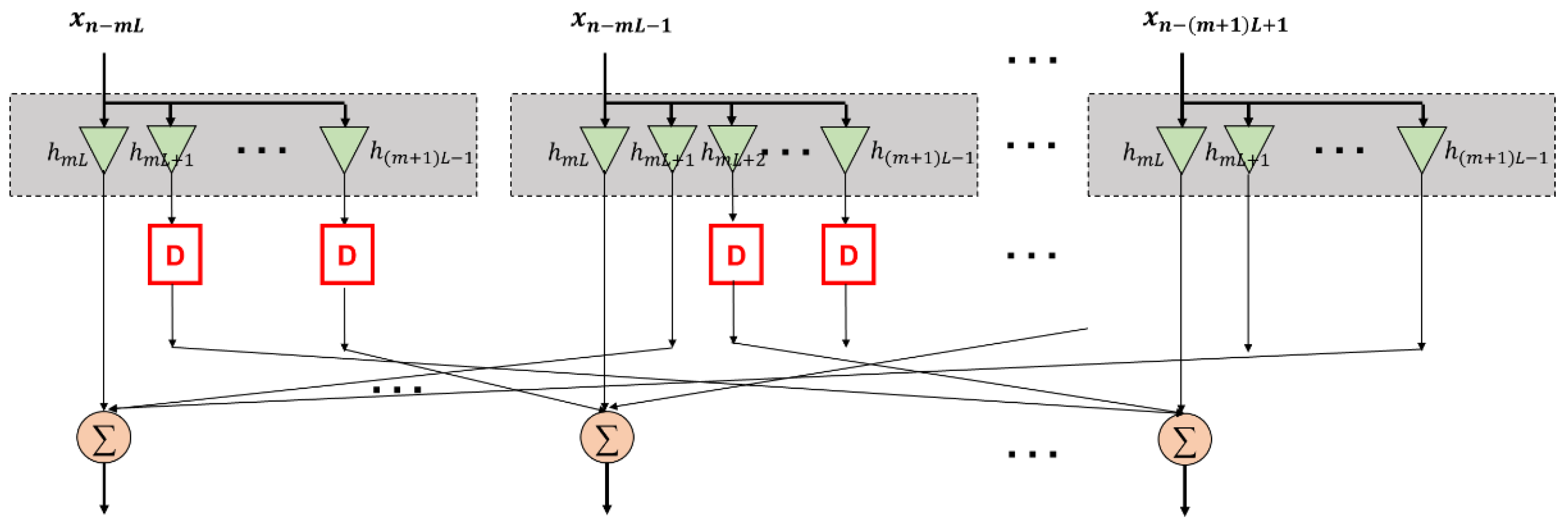
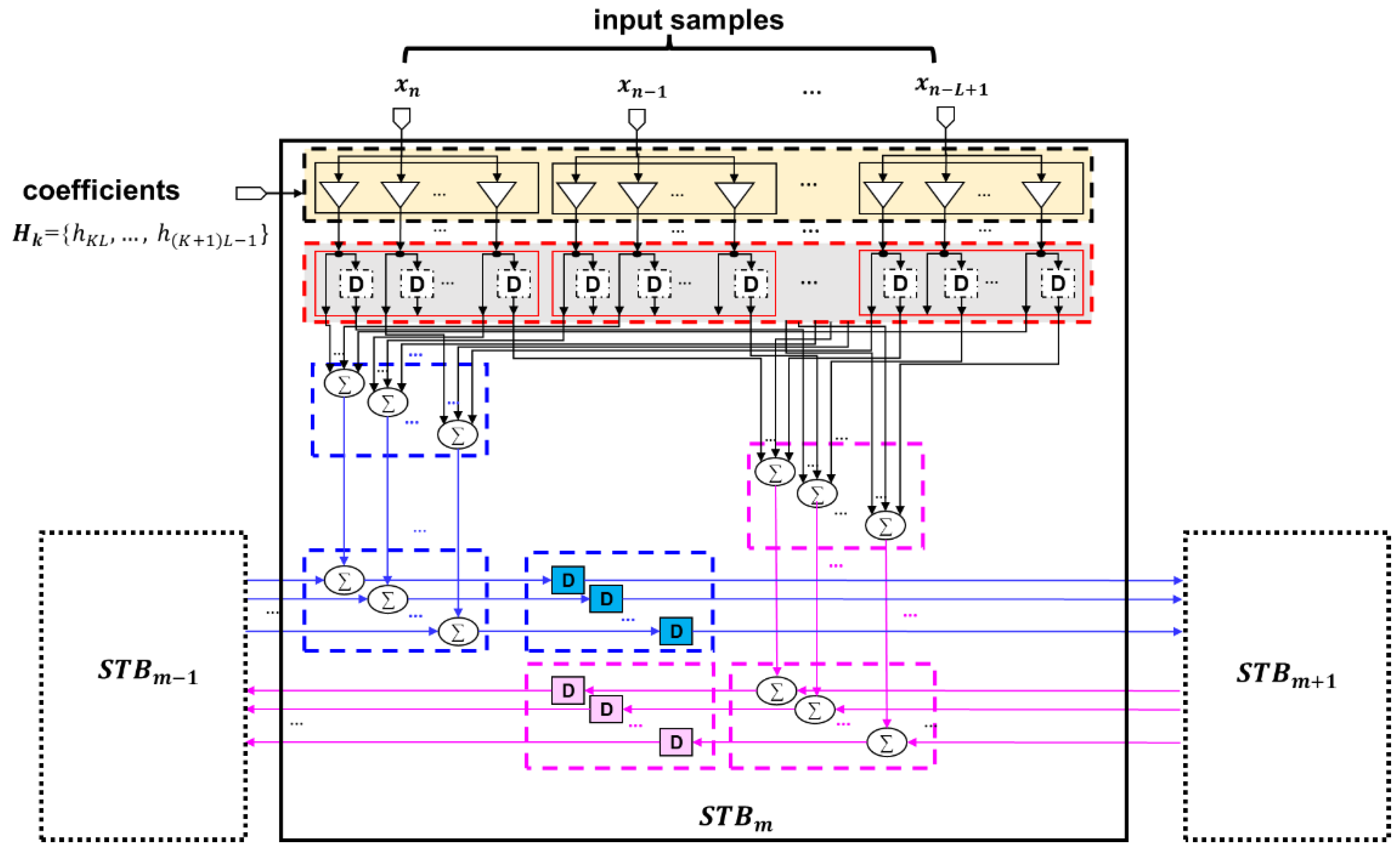
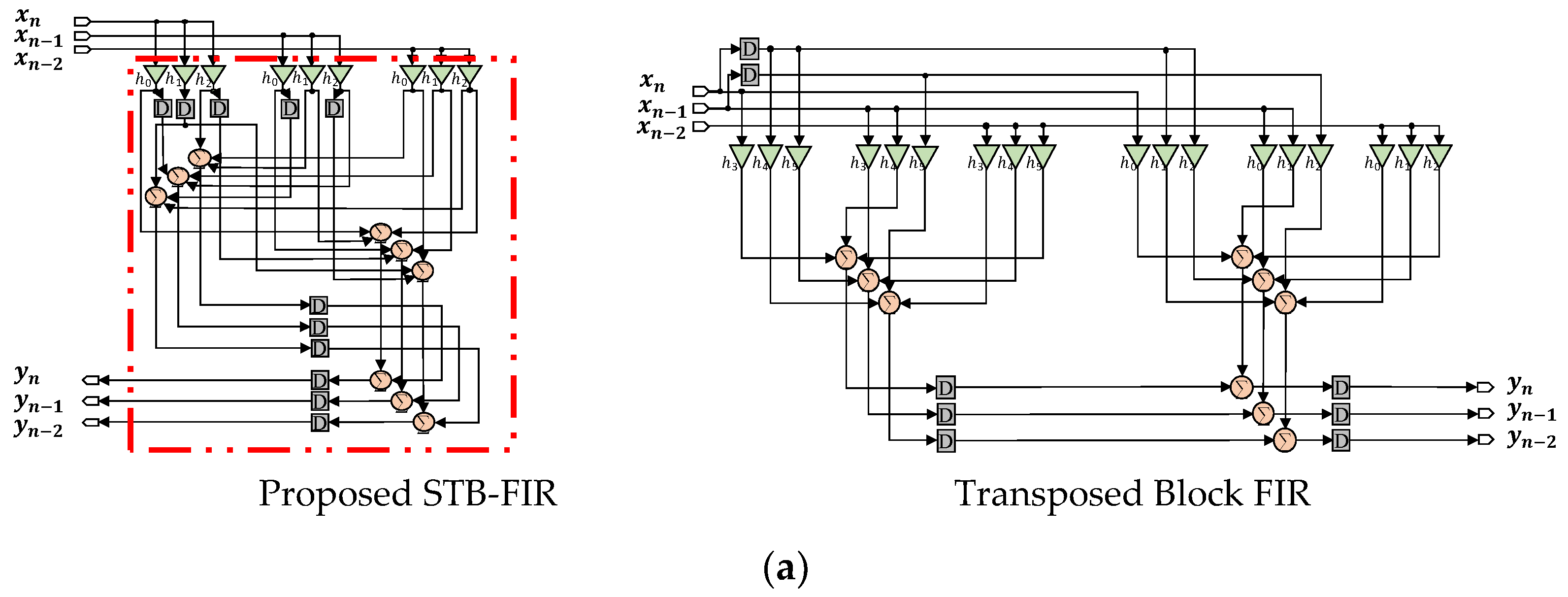
2.2. Proposed STB-FIR Design

For a linear-phase FIR filter, the impulse response can be symmetric ( h i = h T 1 i ) or anti-symmetric ( h i = h T 1 i ) . To simplify the explanation, only the symmetric realization with h i = h T 1 i will be discussed in the following. It is worth noting that the proposed architecture is also able to be applied to anti-symmetric FIR implementations.
As shown in (2), there are 2 L 1 input samples that are multiplied with the corresponding coefficients in each time block. Among the 2 L 1 different input samples, L samples { x n m L ,   x n m L 1 ,   ,   x n m + 1 L + 1 } are the inputs in the current clock cycle while the other L 1 ones { x n m + 1 L ,   x n m + 1 L 1 ,   ,   x n m + 2 L + 2 } were obtained in the previous clock cycle. Therefore, totally L 2 different multipliers are required. In [15], delay elements are inserted on the input side to make it possible for the temporary storage of the L 1 samples for later calculation. Unfortunately, because H i H M 1 i in the transposed block form, the symmetry of coefficients cannot be easily realized.
To explore the feasibility of symmetric convolution in parallel block FIR filters, a hardware efficient symmetric transposed block FIR architecture (STB-FIR) is proposed. In STB-FIR, delay elements are inserted after multipliers; thus, temporal reuse of the intermediate tap products becomes possible. Consequently, half of the multipliers can be saved at the cost of increased registers.
For a T -tap L -parallel transposed FIR with symmetric coefficients where T = M L , there are two cases (i.e., M is odd or even) that should be considered in the proposed STB-FIR design method, as shown in Figure 3.

2.2.1. Case 1: M Is Even

A linear FIR filter that falls into this category has an even tap (i.e., T is even), an even number of TBs (i.e., M is even), and symmetric coefficients (i.e., h i = h T 1 i ). Without loss of generality, let us consider two symmetric TBs ( T B m   and   T B M 1 m ) in a TB-based symmetric FIR.
For the time block, T B m , shown in (6), we can divide it into two terms as below, and each of them can be implemented, as shown in Figure 4a,b, respectively.
T B m = B m · H m = x n m L x n m L 1 x n m + 1 L + 1 x n m L 1 0 x n m + 1 L + 1 x n m + 1 L + 1 0 0 · h m L h m L + 1 h m + 1 L 1 + 0 0 0 0 x n m + 1 L 0 0 x n m + 1 L x n m + 2 L + 2 · h m L h m L + 1 h m + 1 L 1
Here, it should be mentioned that there are 2 L 1 data inputs that are multiplied with the corresponding coefficients ( H m ) in each time block ( T B m ) . Among the 2 L 1 different input samples, if the L samples { x n m L ,   x n m L 1 ,   ,   x n m + 1 L + 1 } are the inputs in the current clock cycle, the other L 1 ones { x n m + 1 L ,   x n m + 1 L 1 ,   ,   x n m + 2 L + 2 } are obtained in the previous clock cycle. Since in transposed form, every input sample should be multiplied with all the coefficients to generate the intermediate tap products, we can conduct the multiplication firstly and then save the products in registers for later addition. By doing this, intermediate products can be reused at the cost of several additional registers, while the required multipliers are reduced by half. As a result, the two parts shown in Figure 4 can be combined into one circuit, as shown in Figure 5, where the current L input samples { x n m L ,   x n m L 1 ,   ,   x n m + 1 L + 1 } are multiplied with all the coefficients firstly in which some of the products will be directly delivered for addition, while some of them are firstly saved into the registers and then sent to the adder.
Furthermore, in a TB-based symmetric FIR (i.e., h i = h T 1 i ), the coefficients in the two symmetric TBs ( T B m and T B M 1 m ) are H m and H M 1 m , respectively, and then we have
H M 1 m = h M 1 m L h M 1 m L + 1 h M 1 m + 1 L 2 h M 1 m + 1 L 1 = h m + 1 L 1 h m + 1 L 2 h m L + 1 h m L = E 1 · H m
where E 1 = 0 1 1 0 providing the vector of coefficients in reverse order, and
T B M 1 m = x n M 1 m L x n M 1 m L 1 x n M 1 m L L 1 x n M 1 m L j x n M 1 m L j + 1 x n M 1 m L L + j 1 x n M 1 m L L 1 x n M 1 m L L x n M 1 m L 2 L 1 · E 1 · H m = x n M 1 m L x n M 1 m L 1 x n M 1 m L L 1 x n M 1 m L 1 0 x n M 1 m L L 1 x n M 1 m L L 1 0 0 · E 1 · H m + 0 0 0 0 x n M 1 m L L 0 0 x n M 1 m L L x n M 1 m L 2 L 1 · E 1 · H m
Although H m H M 1 m , they consist of the same L separate coefficients as { h m L ,   h m L + 1 ,   ,   h m + 1 L 1 }. Since, in transposed form, every input sample should be multiplied with all the coefficients to generate the intermediate tap products, we can implement each pair of symmetric TBs ( T B m and T B M 1 m ) as one symmetric time block ( S T B m ) to take advantage of the same separate coefficients for tap product reuse.
The proposed STB-FIR structure with an even M is shown in Figure 3a, which only consists of the basic STB units, and the detailed STB design is shown in Figure 6. For each STB, it has L data inputs (i.e., x n ,   x n 1 ,   x n 2 ,   , x n L + 1 ) and L coefficients ( H k ) where H k = h k L h k L + 1 h k + 1 L 1 T . It also accepts data from the neighboring STBs, performs the sum operations, and then sends the results to the corresponding two neighboring STBs.
The proposed STB design can be viewed as the combination of two TBs, while the total number of multipliers is reduced by half when compared with the implementation of using two separate TBs. Meanwhile, the number of adders is kept the same as the existing transposed block FIR [15]. Therefore, the number of multipliers can be reduced at the cost of increased delay elements in STB-FIR. Since multipliers are much more expensive in area and power consumption than registers, STB-FIR can achieve significant area and power savings when compared with the existing transposed block FIRs.

2.2.2. Case 2: M Is Odd

When the number of time blocks ( M ) is odd, the FIR structure cannot be fully TB-based folded, and a half-STB unit ( T B M 1 / 2 ) is required, as shown in Figure 3b. Fortunately, due to the symmetry of coefficients (i.e., h i = h T 1 i ), we have
H M 1 2 = h M 1 2 · L h M 1 2 · L + j h M 1 2 · L + L 1 = h M 1 2 · L h M 1 2 · L + 1 h M 1 2 · L
Thus, T B M 1 / 2 can be calculated as
T B M 1 2 = B M 1 2 · H M 1 2 = B M 1 2 · h M 1 2 · L h M 1 2 · L + 1 h M 1 2 · L
Due to the symmetry in H M 1 / 2 , T B M 1 / 2 can be realized using the STB-like unit design only with the length changed from L to [ L 2 ] .
For better illustration, Figure 7 gives the example designs of the proposed STB-FIR and the existing transposed block FIR [15] for two 6-tap transposed FIRs with different degrees of parallelism (L). For the 6-tap 3-parallel transposed FIR (T = 6 and L = 3), because M equals to 2, it is TB-based fully symmetric folded, and the corresponding implementation of the proposed STB-FIR is shown in Figure 7a. Because L = 3 , three data inputs (i.e., x n ,   x n 1 , and x n 2 ) are sent to the STB in each clock. When compared with the transposed block FIR [15], the number of multipliers is reduced from 18 to 9 with the same number of adders, while the number of registers is increased by 3. On the other hand, for the 6-tap 2-parallel transposed FIR (T = 6 and L = 2), as M = 3 , it is not TB-based fully symmetric folded and then a half-STB unit is required, as shown in Figure 7b. Because L = 2 , two input samples (i.e., x n and x n 1 ) are applied in each clock cycle. The STB and the half-STB units work in a similar way as obtaining the data from the neighboring units, performing the sum operations, and then sending the results to the corresponding neighboring units. Finally, two outputs (i.e., y n and y n 1 ) are generated in each clock cycle. When compared with that of [15], the number of multipliers is reduced from 12 to 6 with the same number of adders, and the number of registers is only increased by 2 in STB-FIR.
From this simple example, it can be observed that, unlike the existing transposed block FIR structure [15] in which delay elements are inserted on the input side, the proposed STB-FIR inserts delay elements after multipliers for temporal reuse of tap products. By doing this, the costly multiplier can be reduced by half at the cost of slightly increased low-cost registers.

3. Evaluation Results and Comparisons

To examine the effectiveness of the proposed STB-FIR architecture, implementation results of various FIR filters are provided and compared with the existing works. In our work, all the designs are implemented in ROHM 180 nm CMOS process technology, and the post-synthesis simulation was conducted on the netlist for timing and power evaluation.

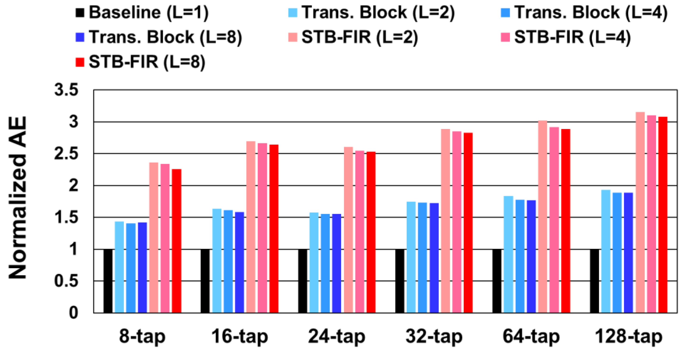
3.1. Comparison of Hardware Complexity

As the general FIR structure, the overall hardware complexity of the proposed STB-FIR is compared with the transposed-based block FIR [15], DA-based approach [13] and FFA-based L-parallel structure [1] in Table 1.
A canonical T -tap FIR filter consists of T multipliers, T 1 adders, and T registers which depends on the tap number ( T ) for specific accuracy requirement. Therefore, a straightforward implementation of a T -tap L -parallel FIR design, L times hardware resources are required. The transposed block structure proposed in [15] involves T L multipliers, L   T 1 adders and T + L 1 registers in which L 1 registers are inserted at the input side for the storage of L 1 samples for later calculation. The required hardware resource of the distributed arithmetic (DA)-based FIR structure [13] is estimated according to the results shown in [15] for comparison purpose. Here, it should be noted that DA [13] was implemented in the direct form, while transposed block [12] was in the transposed form. As for the FFA-based method, the required hardware resource is formulated according to the analysis, as shown in [1,11,12]. As illustrated above, the proposed STB-FIR in total involves T / 2 · L multipliers, L T 1   adders, and T 3 L 2 8 + T registers, among which T 3 L 2 8 registers are approximately used as the delay elements for intermediate product sharing, and the other T registers are required for the output storage of the adder trees.
When compared with DA-based FIR [13] and the transposed block FIR [15], the number of multipliers in STB-FIR can be reduced by half while with the same number of adders, which indicates the promising area savings in STB-FIR. The cost of this multiplier reduction is a slightly increased number of low-cost registers which are used to store the intermediate tap products for temporal reuse. According to our analysis, as L and T increase, the ratio of saved multipliers by the increased registers will get close to 4 / 3 , which indicates that four multipliers can be saved at the cost of three additional registers. Because the area and power of a general multiplier is much larger than the corresponding number of registers, great area and power savings can be achieved in the proposed STB-FIR.

3.2. Comparison of Reconfigurable FIR Implementations

For evaluation and comparison purposes, reconfigurable FIRs in 8, 16, 24, 32, 64, and 128 taps with various degrees of processing parallelism (i.e., L = 2 , 4 , and 8 ) are implemented by using STB-FIR and the existing transposed block FIR [15], and the corresponding synthesis results are shown in Table 2.
In [15], Mohanty et.al have shown that their transposed block FIR designs outperform the existing DA-based method [13]; therefore, we implemented their work as the state-or-the-art design, and the corresponding results are presented in Table 2 for comparison. The results are obtained using the logic synthesis tools, and the power consumption is extracted based on simulation of synthesis results with back-annotation of toggling activity where uniformly distributed sample input values are applied. In the table, the sample frequency is calculated as the degree of parallelism (L)/minimum clock period (MCP). Therefore, it is obvious that the L -parallel FIR designs, including both the proposed method and the existing method, can improve the sampling frequency over the baseline non-parallel FIR design at the cost of increased silicon area. On average, the proposed STB-FIR can achieve 39.12% area savings and 35.16% power consumption reduction for all the 18 FIRs when compared with the existing transposed block-based designs [15].
As the structure of reconfigurable FIR filters is very regular, the measurement of area efficiency per tap (AE) is introduced as
A E = T a p × P a r a l l e l i s m A r e a × M C P
where, Tap is the tap number of the FIR, P a r a l l e l i s m indicates the degree of processing parallelism (i.e., L in the proposed STB-FIR), and M C P is the minimum clock period. The normalized A E results are given in Figure 8 in which the baseline design has the parallelism of 1, and STB-FIR can achieve up to 3.2× A E improvements.

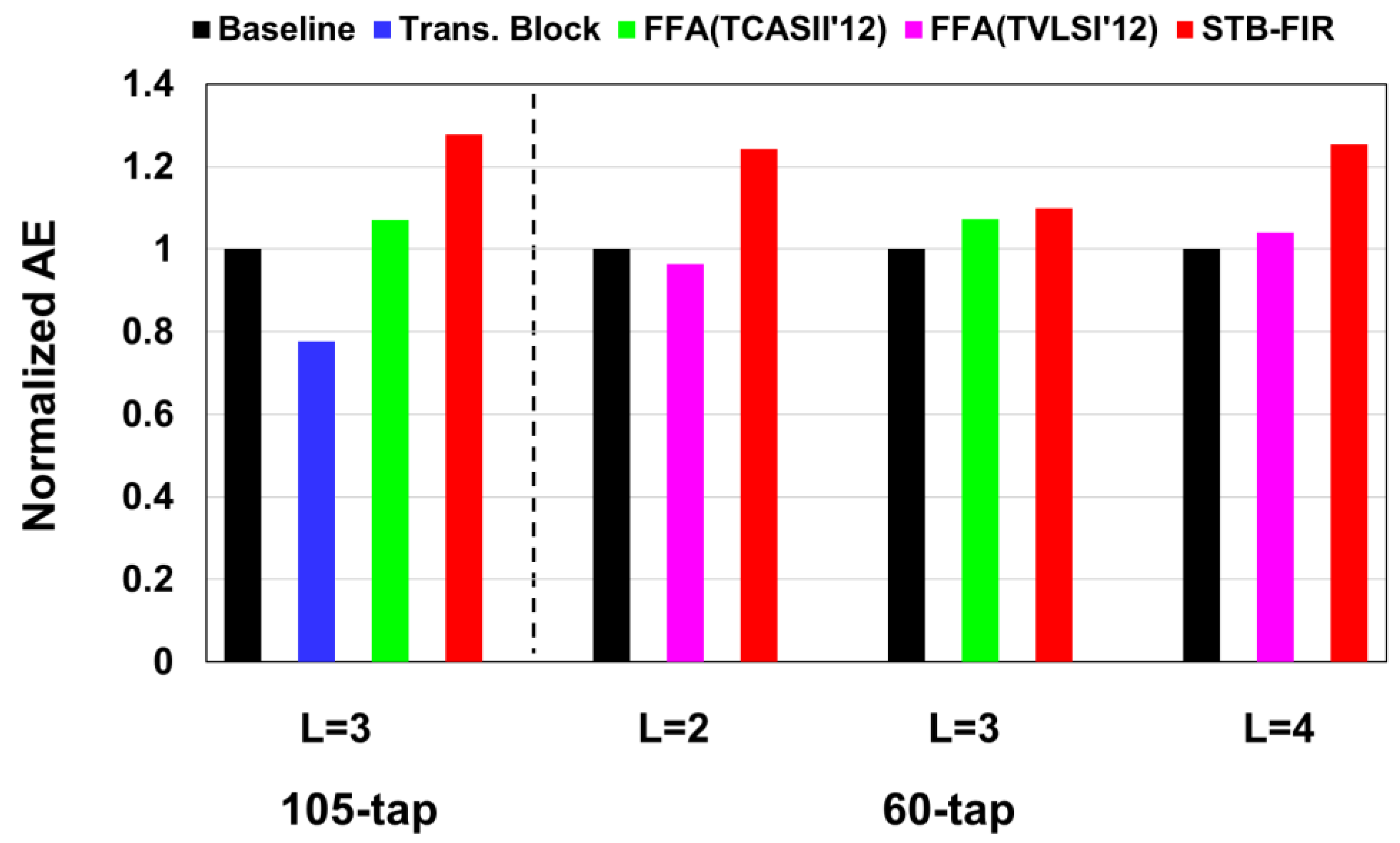
3.3. Comparison of Fixed FIR Implementations

As for fixed FIR filters in which the coefficients are pre-determined, by referring to [16], a 105 -tap FIR with L = 3 and a 60 -tap FIR with L = 2 ,     3 , and 4 are implemented in which the CSE multiplier [4] is adopted for area saving.
For the 105-tap 3-parallel FIR, STB-FIR can achieve 13.08% area saving and 23.05% power reduction when compared with the fixed transposed block FIR [15]. On the other hand, when compared with the fixed symmetric FFA designs [11,12], STB-FIR can achieve up to 31.5% and 40.5% sampling frequency improvement for the 105-tap 3-parallel FIR and the 60-tap 2-parallel one, respectively.
Without loss of generality, the normalized area efficiency comparison is presented in Figure 9 in which the baseline is the FFA-based design in [1]. For the 105-tap 3-parallel FIR, the proposed STB-FIR architecture can achieve 1.64× and 1.20× A E improvements over the transposed block FIR [15] and the fixed symmetric FFA design [11], respectively. Moreover, for the 60 -tap FIR, the proposed STB-FIR filter design can achieve up to 1.29× AE improvement over the existing FFA designs.

4. Conclusions

The feasibility of a symmetric transposed block FIR filter is explored in this paper by taking advantage of the symmetric coefficients for area-power efficient implementation. In the proposed STB-FIR architecture, using registers to save intermediate tap products for temporal reuse makes it possible to realize hardware-efficient symmetric transposed block FIR filters. The evaluation results show that compared with the state-of-the-art reconfigurable architecture [15], the proposed STB-FIR architecture can achieve up to 39.97% and 41.23% area saving and power reduction, respectively. On the other hand, compared with the existing symmetric FFA designs [11,12], the proposed STB-FIR architecture can achieve up to 31.5% and 40.5% sampling frequency improvement and 1.20× AE improvement as well for the fixed FIR implementations. These results clearly illustrate the efficiency of the proposed STB-FIR architecture and confirm that STB-FIR can be applicable to both reconfigurable and fixed FIR implementations for area-power efficient high-speed signal processing. On the other hand, the optimization of multipliers will result in an increased importance of adder trees, especially in fixed FIRs. Therefore, further optimization of adder tree implementation will be one of our future works.

Author Contributions

Conceptualization, J.Y. and Y.S.; methodology, J.Y.; validation, J.Y., M.Y. and Y.S.; data curation, J.Y.; writing—original draft preparation, Y.S.; writing—review and editing, J.Y., M.Y. and Y.S. All authors have read and agreed to the published version of the manuscript.

Funding

This research was supported in part by Waseda University Grant for Special Research Projects (Project number: 2021C-147).

Institutional Review Board Statement

Not applicable.

Informed Consent Statement

Not applicable.

Data Availability Statement

All the necessary data are included in the article.

Conflicts of Interest

The authors declare no conflict of interest.

References

  1. Parhi, K.K. VLSI Digital Signal Processing Systems: Design and Implementation; Wiley: New York, NY, USA, 1999. [Google Scholar]
  2. Mirchandani, G.; Zinser, R.L.; Evans, J.B. A new adaptive noise cancellation scheme in the presence of crosstalk [speech signals]. IEEE Trans. Circuits Syst. II Analog. Digit. Signal Process. 1995, 39, 681–694. [Google Scholar] [CrossRef]
  3. Dempster, A.G.; Macleod, M.D. Use of minimum-adder multiplier blocks in FIR digital filters. IEEE Trans. Circuits Syst. II Analog. Digit. Signal Process. 1995, 42, 569–577. [Google Scholar] [CrossRef]
  4. Mahesh, R.; Vinod, A.P. A new common subexpression elimination algorithm for realizing low-complexity higher order digital filters. IEEE Trans. Comput. Aided Des. Integr. Circuits Syst. 2008, 27, 217–229. [Google Scholar] [CrossRef]
  5. Lou, X.; Yu, Y.J.; Meher, P.K. Fine-grained critical path analysis and optimization for area-time efficient realization of multiple constant multiplications. IEEE Trans. Circuits Syst. I Regul. Pap. 2015, 62, 863–872. [Google Scholar] [CrossRef]
  6. Meidani, M.; Mashoufi, B. Introducing new algorithms for realizing an FIR filter with less hardware in order to eliminate power line interference from the ECG signal. IET J. Signal Process. 2016, 10, 709–716. [Google Scholar] [CrossRef]
  7. Ye, J.; Togawa, N.; Yanagisawa, M.; Shi, Y. A low cost and high speed CSD-based symmetric transpose block FIR implementation. In Proceedings of the IEEE International Conference on ASIC (ASICON), Guiyang, China, 25–28 October 2017. [Google Scholar]
  8. Ye, J.; Togawa, N.; Yanagisawa, M.; Shi, Y. Static error analysis and optimization of faithfully truncated adders for area-power efficient FIR designs. In Proceedings of the IEEE International Symposium on Circuits and Systems (ISCAS), Sapporo, Japan, 26–29 May 2019. [Google Scholar]
  9. Park, J.; Jeong, W.; Meimand, H.M.; Wang, Y.; Choo, H.; Roy, K. Computation sharing programmable FIR filter for low-power and high-performance applications. IEEE J. Solid-State Circuits 2004, 39, 348–357. [Google Scholar] [CrossRef]
  10. Parker, D.A.; Parhi, K.K. Low-area/power parallel FIR digital filter implementations. J. VLSI Signal Process. Syst. 1997, 17, 75–92. [Google Scholar] [CrossRef]
  11. Tsao, Y.; Choi, K. Area-efficient parallel FIR digital filter structures for symmetric convolutions based on fast FIR algorithm. IEEE Trans. Very Large Scale Integr. Syst. 2012, 20, 366–371. [Google Scholar] [CrossRef]
  12. Tsao, Y.; Choi, K. Area-efficient VLSI implementation for parallel linear-phase FIR digital filters of odd length based on fast FIR algorithm. IEEE Trans. Circuits Syst. II Express Briefs. 2012, 59, 371–375. [Google Scholar] [CrossRef]
  13. Mohanty, B.K.; Meher, P.K. A high-performance energy-efficient architecture for FIR adaptive filter based on new distributed arithmetic formulation of block LMS algorithm. IEEE Trans. Signal Process. 2013, 61, 921–932. [Google Scholar] [CrossRef]
  14. Mohanty, B.K.; Meher, P.K.; Al-Maadeed, S.; Amira, A. Memory footprint reduction for power-efficient realization of 2-D finite impulse response filters. IEEE Trans. Circuits Syst. I Regul. Pap. 2014, 61, 120–133. [Google Scholar] [CrossRef]
  15. Mohanty, B.K.; Meher, P.K. A high performance FIR filter architecture for fixed and reconfigurable applications. IEEE Trans. Very Large Scale Integr. Syst. 2016, 24, 444–452. [Google Scholar] [CrossRef]
  16. Shahein, A.; Zhang, Q.; Lotze, N.; Manoli, Y. A novel hybrid monotonic local search algorithm for FIR filter coefficients optimization. IEEE Trans. Circuits Syst. I Regul. Pap. 2011, 59, 616–627. [Google Scholar] [CrossRef]
Figure 1. General FIR implementations: (a) direct form and (b) transposed form.
Electronics 11 03272 g001
Figure 2. Time-block-based transposed block FIR architecture.
Electronics 11 03272 g002
Figure 3. Proposed STB-FIR structure with two cases: (a) TB-based fully symmetric folded structure when M is even and (b) non-symmetric folded structure when M is odd.
Electronics 11 03272 g003
Figure 4. Implementation of the time block, T B m , with the corresponding two terms in (7): (a) the form term and (b) the latter term.
Electronics 11 03272 g004
Figure 5. Combined implementation of the two circuits shown in Figure 4.
Electronics 11 03272 g005
Figure 6. STB design in the proposed STB-FIR.
Electronics 11 03272 g006
Figure 7. Comparisons of parallel FIR implementations (proposed STB-FIR vs. transposed block FIR). (a) Implementations of a 6-tap 3-parallel FIR (T = 6, L = 3 and M = 2) and (b) implementations of a 6-tap 2-parallel FIR (T = 6, L = 2 and M = 3).
Electronics 11 03272 g007aElectronics 11 03272 g007b
Figure 8. Normalized AE results of various reconfigurable FIR implementations.
Electronics 11 03272 g008
Figure 9. Normalized AE results of various fixed FIR implementations.
Electronics 11 03272 g009
Table 1. Comparisons of various parallel FIR architectures.
Architecture.No. of
Multipliers
No. of
Adders
No. of
Registers
Transposed
block
T L L T 1 T + L 1
DA T L L T 1 T + L 1
L-Parallel
FFA
T i = 1 r L i i = 1 r M i A 1 i = 1 r L i + i = 2 r A i j = i + 1 r L j k = 1 i 1 M k + i = 1 r M i T i = 1 r L i 1 T L R 1 i = 2 r M i + R r + T
Proposed
STB-FIR
T / 2 L L T 1 T 3 L 2 8 + T
* In DA, the number of multipliers indicates the required LUT-based multiplier blocks. * In L -Parallel FFA, L = i = 1 r L i , and M i ,     R i   , and A i   indicate the number of multipliers, registers, and adders of the ith parallel FFA basic unit ( L i ) , respectively. * For the registers in STB-FIR, T 3 L 2 8 is an approximate value depending on M and L .
Table 2. Comparisons of various parallel FIR architectures.
TapFIR StructureNo. of MultipliersNo. of AddersNo. of RegistersSampling Freq. (MHz) Area   ( u m 2 ) Area Saving (%)Power (mw)Power Saving (%)
8Parallel
L = 2
Transposed block16149207.04203,38039.3512.4734.40
Proposed STB-FIR81410206.83123,3538.18
Parallel
L = 4
Transposed block322811382.78383,34339.9721.7234.16
Proposed STB-FIR162818382.41230,12714.30
Parallel
L = 8
Transposed block645615735.97731,51437.3942.1735.83
Proposed STB-FIR325630733.27457,99327.06
16Parallel
L = 2
Transposed block323017207.04410,74539.2826.2937.31
Proposed STB-FIR163024206.83249,38416.48
Parallel
L = 4
Transposed block646019382.78769,61539.4944.7236.67
Proposed STB-FIR326036382.41465,66128.32
Parallel
L = 8
Transposed block12812023717.491,474,40939.0388.3941.23
Proposed STB-FIR6412060732.60898,99451.95
24Parallel
L = 2
Transposed block484625207.04618,29339.6634.9636.13
Proposed STB-FIR244636206.83373,09922.33
Parallel
L = 4
Transposed block969227382.781,155,88739.0764.9936.42
Proposed STB-FIR489254382.41704,29041.32
Parallel
L = 8
Transposed block19218431733.272,217,48338.81120.6532.95
Proposed STB-FIR9618490732.601,356,81980.90
32Parallel
L = 2
Transposed block646233207.04827,37939.6250.4032.34
Proposed STB-FIR326248206.83499,54234.10
Parallel
L = 4
Transposed block12812435382.781,542,08239.2688.2233.51
Proposed STB-FIR6412472382.41936,72758.66
Parallel
L = 8
Transposed block25624839733.272,963,93939.00159.9633.09
Proposed STB-FIR128248120732.601,808,023107.03
64Parallel
L = 2
Transposed block12812665207.041,613,97739.2999.8336.44
Proposed STB-FIR6412696206.83979,80263.45
Parallel
L = 4
Transposed block25625267382.783,087,82839.30177.3234.97
Proposed STB-FIR128252144382.411,874,254115.32
Parallel
L = 8
Transposed block51250471733.275,932,52338.87322.6433.07
Proposed STB-FIR256504240732.603,626,413215.93
128Parallel
L = 2
Transposed block256254129207.043,272,25838.90208.1136.97
Proposed STB-FIR128254192206.831,999,407131.18
Parallel
L = 4
Transposed block512508131382.786,178,50739.12356.0534.70
Proposed STB-FIR256508288382.413,761,321232.5
Parallel
L = 8
Transposed block10241016135733.2711,872,90438.82648.1632.76
Proposed STB-FIR5121016480732.607,263,638435.81
Publisher’s Note: MDPI stays neutral with regard to jurisdictional claims in published maps and institutional affiliations.

