Article

Emission Features and Structure of an Electron Beam versus Gas Pressure and Magnetic Field in a Cold-Cathode Coaxial Diode

1
Lebedev Physical Institute, RAS, 119991 Moscow, Russia
2
Institute of High Current Electronics, SB RAS, 634055 Tomsk, Russia
3
Institute of Electrophysics, UB RAS, 620016 Yekaterinburg, Russia
*
Author to whom correspondence should be addressed.
Electronics 2022, 11(2), 248; https://doi.org/10.3390/electronics11020248
Submission received: 3 December 2021 / Revised: 2 January 2022 / Accepted: 11 January 2022 / Published: 13 January 2022

Abstract

:
The structure of the emission surface of a cold tubular cathode and electron beam was investigated as a function of the magnetic field in the coaxial diode of the high-current accelerator. The runaway mode of magnetized electrons in atmospheric air enabled registering the instantaneous structure of activated field-emission centers at the cathode edge. The region of air pressure (about 3 Torr) was determined experimentally and via analysis, where the explosive emission mechanism of the appearance of fast electrons with energies above 100 keV is replaced by the runaway electrons in a gas.

1. Introduction

Currently, in the field of high-power microwave (HPM) generation (see, e.g., Refs. [1,2], and citations therein), research on the phase-stable excitation of high-current electron generators is ongoing [3,4,5,6,7,8,9,10,11]. Along with the use of external radiation sources [12,13,14,15], this mode is possible when a seed electromagnetic (EM) signal appears at a stable front of the beam, and has the required power and spectral range [16,17]. The higher the generation frequency, the shorter the current front needed, and in millimeter wave range, this is at the sub-nanosecond scale. Explosive electron emission (EEE) beams with such edges and duration ≤ 1 ns [18] are used in Ka-band HPM generators operating in the superradiance (SR) mode and form EM pulses with a duration of about ten oscillation periods [19,20,21,22]. In-phase SR generators and their longer-pulse counterparts have already demonstrated coherent summation of the radiation from several autonomous channels [23,24,25,26]. The use of SR pulses with stable phase, amplitude, and duration for high-gradient acceleration (HGA) of electrons in extreme microwave fields [27] is promising because their ultrashort exposure may result in a delay in the breakdown of electrodynamic structures [22], including technical vacuum conditions.
In the context of the HGA problem, in Ref. [28], the prospect of using high-frequency (≈100 GHz and more) SR generators is noted [29,30]. In particular, the source [30] increases the peak generation power and enables phase locking. This requires an increase in the current and diameter of the tubular driving beam while maintaining the stability of the emission instant and the rising rate for the leading edges of <100 ps. These issues are also relevant for HPM generators of various types [31,32,33].
In this study, we considered conditions for increasing a beam current for a magnetically insulated coaxial diode (MICD) with a tubular cathode, where the length of the accelerating gap (D), material of the cold cathode, magnitude of the longitudinal magnetic field (B), and the residual gas pressure (p), were varied. Experimental techniques and diagnostic methods are described below in Section 2.
In addition to the current magnitude, the azimuthal homogeneity of a short tubular beam is important for applications, and is associated with the structure of the emission surface of the cathode and the magnitude of the longitudinal magnetic field [34]. However, in a wide range of residual gas pressures, these issues have not yet been considered. In particular, at the limit of high gas pressure up to atmospheric pressure [35,36,37,38,39,40,41,42], the picture of electrons’ origin changes dramatically. In this case, the gas itself becomes a supplier of fast runaway electrons (RAE) in the form of jets, which are tied to the centers of the field emission (FE) at the cathode [43] and have picosecond duration [44,45,46]. In the case of RAEs’ emission, the energy lost by particles during impact ionization is much less than that acquired by them during acceleration in an electric field between inelastic collisions with molecules [35,36,38,47]. As a result, RAEs are accelerated “almost like in a vacuum”. Data on the homogeneity of such a beam are presented in Section 3.2. This follows Section 3.1, which includes general remarks on all experiments.
Regarding the attainable beam current amplitudes, of primary interest is the range of residual gas pressure [48], where the “vacuum” EEE mechanism [49] is transformed and supplemented by the generation of RAEs in the gas (Section 3.3). We assumed that, at the transformation stage, the presence of RAEs and accompanying ionization processes can lead to the “gas amplification” of the current [47,50] already at the leading edge of the formed beam. An interpretation of these effects is provided in Section 3.4.

2. Experimental Setup and Diagnostic Methods

In the experiments, an injection-measuring unit shown in Figure 1a was used, representing the MICD with a pulsed solenoid providing B-field induction of up to ≈4 T. The cold tubular cathode and the anode have diameters of 22 and 45 mm, respectively, and the anode constriction has a bore diameter of 25 mm. The diagnostic sensor was positioned behind the constriction. This was a current probe with electron collector diameter 2Rec = 25 mm, in front of which a 15 μm thick transparent aluminum foil was placed for electrons with energies higher than ≈40 keV [51], and (if necessary) a disk segment collimator made of graphite, which reduces the current (EEE-beam) by 3.7 times. The foil and collector formed a disk line, which then became a low-resistance coaxial line (7 Ohm). The transition was not matched. Therefore, the current bursts with a duration comparable to or less than 2Rec/c ≈ 83 ps (c is the speed of light) during registration, causing multiple reflections (noise) on the oscillogram; this noise was partially eliminated (averaged) by reducing the registration bandwidth to 8 GHz or less. A registering capacitive voltage divider was located in the measuring coaxial section of the current probe, which made it possible to observe signals with edges of up to 70 ps. However, this sensor, which had a limited area (a circle with a diameter of 20 mm), was also characterized by the presence of reflections after the useful signal. Under these conditions, the probe with a large-aperture collector, when the oscilloscope’s recording band was reduced, formed a broadened “current” signal, the amplitude of which could be significantly reduced. Therefore, in a number of experiments (at atmospheric pressure), a fast-response current probe [52] with a receiving window aperture having a diameter of 9 mm was used. Previously, this probe allowed observing the RAE current leading edges of up to 20 ps [46], but in our experiment it recorded only a narrow segment of a tubular beam.
Figure 1b–d show variants of the cathodes used in the experiments. Note that a sufficiently large diameter of any of the tubular cathodes shown (22 mm) was chosen in the experiments for two reasons. Firstly, we were interested in the operation of the cathodes with an increased diameter, due to the promising trend of increasing beam current in the SR generator [30]. Secondly, this diameter made it possible to bring high-voltage pulses to the cathode emission edge with minimal reflections throughout the entire section of the coaxial transmission line (CTL), starting from the high-voltage generator. This duct with characteristic impedance ρ = 44 Ohm, including oil-filled, bushing, and vacuum sections, had variations of no more than ±0.5 Ohm. As a result, it was possible to apply the method of dynamic time-domain reflectometry (DTDR) [53], which allows one to use two remote and space-shifted CTL probes (Figure 2a) to determine a reflected voltage pulse from the load (cathode) without distortion, and then restore the voltage at the cathode and the emission current (of the beam) or the discharge current in the MICD gap.
Figure 1e shows the adjustable voltage pulses used in the experiments. These pulses were created by a high-voltage generator which included the RADAN-303 5-nanosecond driver [54] and inductive-capacitive pulse compression unit [55] with sharpening and cut-off nitrogen spark gaps [56]. The pulse full width at half maximum (FWHM) was varied from ≈200 to ≈500 ps. This was significantly less than the limitations of the DTDR method for non-distorting registration with a delay time between the signals of two probes (P1 and P2) of 2τ2 = 4 ns. The delay τ1 of reflection Uref from the load toward the near probe P1 was determined with an accuracy of ±5 ps in no-load mode (Figure 2b) when an incident pulse had the minimum amplitude and duration (Figure 1e), and the absence of emission in gas or vacuum was provided by a small amplification of the electric field on a smooth steel edge of the cathode (Figure 1d), which was previously trained (polished) in vacuum [57,58]. In this mode, the difference in the amplitudes of incident (U1) and reflected (Uref) pulses in Figure 2b due to dispersion and losses in the CTL gave the correction factor (K ≈ 1.15 ± 0.05) for estimating the voltage at the cathode in the mode of electron emission in vacuum or gas.
To visualize the structure of tubular RAE flow in anodic constriction cross-section, instead of the current collector, an AGFA-CPG400 fluorescent screen having a diameter of 25 mm with a Gd2O2S:Tb phosphor was installed. The screen was covered from the cathode side with thin black paper, which excluded illumination from the MICD volume when taking photos with an open shutter. In the experiments, for contrasting images, the camera sensitivity (ISO) and the lens aperture could be changed, or neutral optical filters of different densities were used.

3. Results, Comments, and Interpretation

3.1. General Remarks

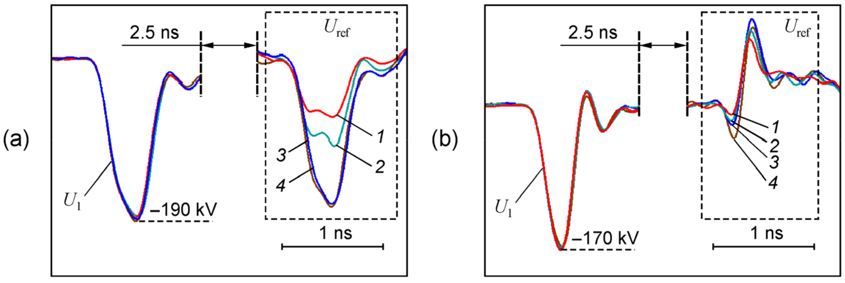
Figure 3 presents a set of typical oscillograms of voltage pulses obtained in the modes of MICD operation in vacuum (Figure 3a) and at atmospheric pressure (Figure 3b) for various accelerating gaps D and cathode materials. When a beam is emitted in vacuum, reflection Uref from the cathode has the same negative polarity as the incident voltage pulse U1. The amplitude of Uref decreases (modulo) with decreasing gap D, but this is more pronounced for a graphite cathode, on which EEE develops faster, and with a limited duration of U1, the higher beam current is reached earlier (see Section 3.3). Note that the voltage at the cathode Uc(t) can be determined as the sum of U1(t) + Uref(t), if these voltage pulses are “synchronized” taking into the account the delay τ1 defined above, and the pulse Uref(t) is restored by the DTDR method [53]. In addition, for the vacuum approximation, one can calculate dynamic impedance Z(t) of the MICD and the current in the load (i.e., current of the beam or discharge) IL(t): Z(t) = ρ [(U1(t) + Uref(t))/(U1(t) − Uref(t))] and IL(t) = 2U1(t)/(Z(t) + ρ), respectively.
Formation of a picosecond RAE flow in a gas begins at the leading edge of the voltage pulse U1(t), when a critical electric field Ecr is achieved near the cathode edge (at the boundary of plasma formations near FE centers), which is sufficient for thermal electrons to run away [47]. As a result, for the passage of RAEs to the anode constriction, special criteria are fulfilled in our case [59]. As seen in Figure 3b, the smaller the MICD gap D, the smaller the (modulo) amplitude of a non-inverted part of the pulse Uref(t). This is due to an increase in the electric field near the cathode at given parameters of the leading edge of the pulse U1(t). In addition, due to the finer-grained structure of FE centers on graphite and their earlier activation, the Uref amplitude for the graphite cathode is smaller than for a steel one. The voltage amplitude at the cathode during RAEs’ emission in gas can be estimated from oscillograms as Uc(t) ≈ 2KUref(t), because the cathode operates in an idle mode before the appearance of fast electrons. When RAEs pass through the MICD gap, an ionization trace appears [38,60,61,62,63] and then the discharge current arises. As a result, we observe an inverted section of Uref(t) and, during the polarity reversal, the voltage across the MICD gap decreases rapidly [64]. An amplitude of the inverted pulse is determined not only by residual resistance of the discharge gap, but also by the duration of U1(t). If for excessively short U1(t) the RAE flow does not reach the anode during the pulse duration, a discharge current does not have time to develop [65], and then the positive lobe of Uref(t) is absent.
Note that the tendency for the pulse Uref(t) polarity to reverse is an indicator of “switching on” the ionization and discharge processes when the pressure of residual gas in the MICD is varied. It is also important that in our experiments it is appropriate to compare the temporal emission characteristics for different cathodes and at variations in the gas pressure by analyzing the pulses Uref, because these reflections have an absolute time reference. Indeed, the position of the cathode’s emission edge along the longitudinal coordinate did not change, and variation in the gap distance D (10 or 30 mm) was achieved by displacing the anode constriction.

3.2. Azimuthal Structure of the RAE Beam and Its Emission Stability

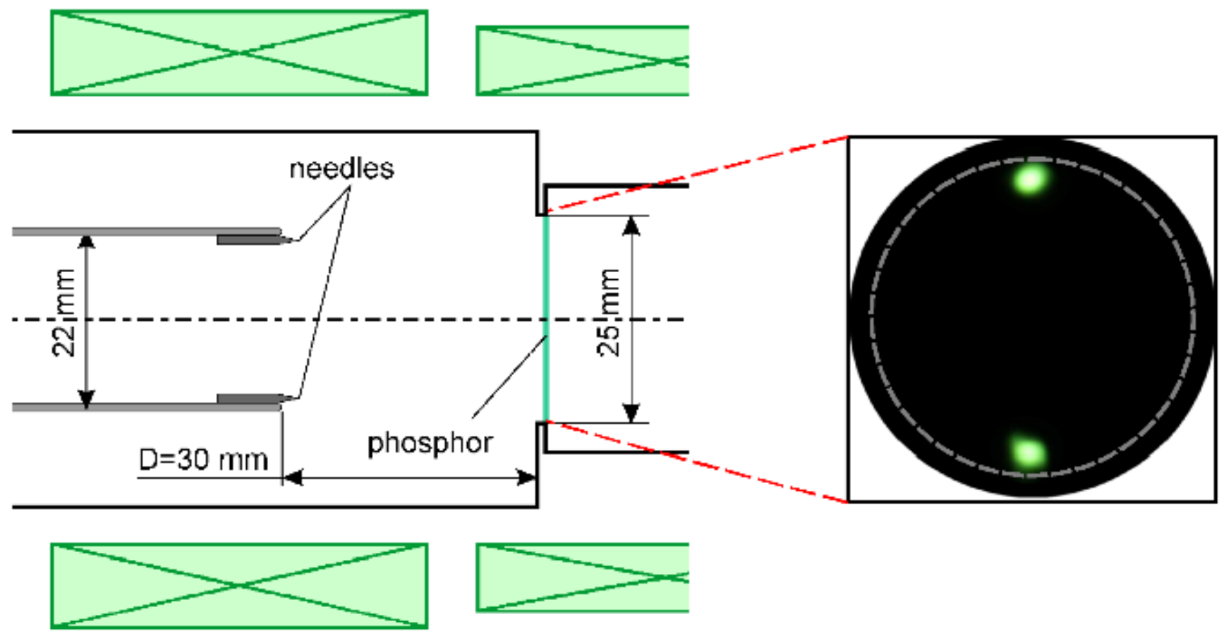
Both modes under investigation, namely EEE in vacuum and RAE emission in gas, have a common preliminary stage, i.e., field emission at microinhomogeneities of the cathode [43,66,67,68]. At atmospheric pressure, elementary RAE flow is extremely short (up to 10 ps, [69,70]). Thus, an open shutter photograph of the RAE beam reprinted on a luminescent screen accumulates emission events from the cathode occurring within an interval of about ten picoseconds. Taking into account the “single” actuation of FE centers during RAE emission, the structure of the magnetized tubular beam on the collector carries information about their “instantaneous” location at the cathode. For this, the beam should consist of a set of jets (bunches), which on their way to the anode do not shift in azimuth (do not mix). The absence of jet displacement was examined in an experiment, where amplitude of U1(t) was minimized as in Figure 2b so that there was no RAE emission from a smooth semithoroidal edge of a steel cathode (Figure 1d). However, two diametrically opposite RAE jets (Figure 4) from similarly oriented needles protruding from the cathode edge by 1 mm were observed on the phosphor. That is, azimuthal displacement of jets with a current of less than 1 A each did not occur at an acceleration distance D = 30 mm.
Taking into account the previous result, we can consider the autographs of “multi-jet” tubular flows of RAEs (Figure 5). The general tendency here is that with an increase in the magnetic field, the number of jets increases and the beam acquires azimuthal homogeneity. In a strong field (B = 4.3 T), homogeneity also increases with an increase (modulo) in the RAE emission voltage at the cathode (│Ucmax ≈ 2K∙Urefmax) for both graphite and steel. Apparently, this is due to effective activation of a larger number of FE centers having a spread in the field amplification coefficients β. Note that a higher emission voltage of RAEs is realized at a steel cathode, which is associated with the requirement to increase the electric field on steel micro-emitters with a smoother relief than on graphite.
In the case of a graphite cathode (D = 30 mm), the beam is thinnest at B = 4.3 T and represents a continuous set of adjacent jets with a diameter of ≈1 mm and a current of hundreds of milliamperes each. In this case, their number corresponds to the beam circumference (in millimeters) with an accuracy of ±1. Apparently, such a regular positioning is determined by an effect similar to the screening of the emission edge of the EEE cathodes in a magnetic field in the case of vacuum emission [34]. In the latter case, the space charge of electron flowing from the active EEE leader centers (plasma flares) reduces the field at neighboring FE centers, which are abundant on graphite. In a gas version, the screening appears to come from FE electrons [71] and the secondary (plasma) particles, which begin to accelerate rapidly in the region of a macroscopic electric field, which is enhanced near the cathode edge.
Note the increased radial thickness of the magnetized RAE beam (Figure 6a) compared to the vacuum EEE current (Figure 6b). In a vacuum, an imprint was obtained on a polymer film instead of a luminescent screen. This increase is consistent with numerical simulation of particle trajectories for the vacuum approximation shown in Figure 6d [72,73] and with estimation using formula (12) in Ref. [74]. The increase is explained by the fact that the source of fast electrons in gas is the plasma, which arises due to ionization of molecules by FE electrons. These particles can appear much earlier, including the nanosecond voltage prepulse. That is, plasma formations have time to expand by hundreds of microns by the time the critical field is reached at their boundary. This means that the emission surface of the cathode in gas initially has a much larger radial size compared to the vacuum regime, where EEE plasma flares insignificantly expand (tens of microns) during the nanosecond interval at the rate of 2 × 106 cm/s [49] and, unlike [75], the thickness of the emission edge (≈100 μm in our case, Figure 1b,c) does not change for a few nanoseconds. As a result, the vacuum EEE beam is thin in a strong magnetic field (Figure 6c). Moreover, the factor leading to the radial expansion of the RAE flow is the scattering of electrons due to elastic collisions with gas molecules.
Let us note a specific feature of the RAE beam emission from graphite. Because in any region of the cathode edge there are many small microprotrusions with large coefficients β, then, on average, the FE initiation of gas ionization begins in different regions rather synchronously. As a result, plasma formations (sources of RAEs) appear with a small time spread. Removal of a certain part of graphite (during breakdowns) changes the emission edge structure only slightly because graphite has a finely dispersed homogeneous structure. Therefore, the emission of the RAE flow is reproduced from pulse to pulse with picosecond accuracy. This is shown in Figure 7a in the measurement by a fast-response probe for the case as in Figure 5 at D = 30 mm, B = 2.1 T. Here, the total time spread of the current pulses at a fixed level at the front is measured relative to the voltage leading edge. It is in the range of 5–10 ps, and reproduces from series to series. Similar data for a steel cathode gives 5–10 times greater time spread (Figure 7b). This is due to asynchronous emission of the RAE jets from different sections of the cathode edge, because the FE centers have an inhomogeneous structure, and parameter β is, on average, less than that for graphite. The RAE emission delay for steel relative to graphite (>20 ps) and increased emission voltage determine the rise in the maximum RAE beam current, up to 50 A.
The high stability of the RAE current emission from graphite makes it possible to estimate the RAE energy by the time-of-flight method from displacement of the current peak when the collector was moved to some distance L. In our case, L = 6 cm, and the shift in the current peak in Figure 7a by 315 ps corresponded to kinetic energy of 150 keV. Taking into account the amplitude of the non-inverted peak of Uref, we found that the voltage at the cathode Uc did not exceed (modulo) 85 kV. That is, RAE acceleration in the main part of the gap occurred in the electric field “compressed” ahead of the plasma front of the ionization wave [60,61,62,69]. In our case, the plasma is magnetized and therefore has an increased density. Apparently, this determines the efficiency of the field compression [76] and an almost twofold increase in the RAE energy at the collector in comparison with eUc (e-electron charge).

3.3. Transition from the EEE Emission to the Electron Runaway in a Gas

In [77], it was shown that the current amplitude of a magnetized nanosecond explosive emission beam in the vacuum MICD at a pressure of 5 × 10⁻³ Torr increases significantly if, with an advance of hundreds of nanoseconds, the accelerating gap passes a sub-nanosecond beam from the same cathode (the effect of double pulses). The observed effect was explained by the charge neutralization of the electron flow by the plasma moving from the cathode. This plasma channel appeared in the presence of the leading pulse due to the expansion of the magnetized EEE plasmas and plasma arising from effective impact ionization of residual gas near the cathode. Here, the ionization cross sections are large due to the low electron energy.
We assumed that, with an increase in the residual gas pressure, a sufficiently dense plasma channel (tube) can arise when a picosecond runaway electron flow passes ahead of time in the accelerating gap, and this does not require an additional voltage pulse and a beam. The reason is that, after activation of the FE centers at the cathode, even at p = 760 Torr, the RAE flow appears with low inertia—in fact, at an instant when high-current EEE in vacuum is just beginning (Figure 8). Note that the RAE current pulse in this figure was obtained with insufficient time resolution by the probe adapted to measure a kiloampere-range EEE current. A more realistic current envelope of RAEs is represented by the signal in Figure 7a.
At pressure of <760 Torr, the RAE emission begins at lower voltages (that is, earlier at the leading edge of the pulse Uc(t)) due to a decrease in the field Ecr. In particular, in [78], data are given on the regime of a complete runaway of all free electrons in the gap with a decrease in pressure to ≈300 Torr. For p = 760 Torr, such a regime is also possible, but a rapid increase in the field in the gap to high strengths (≈1 MV/cm) is required [79].
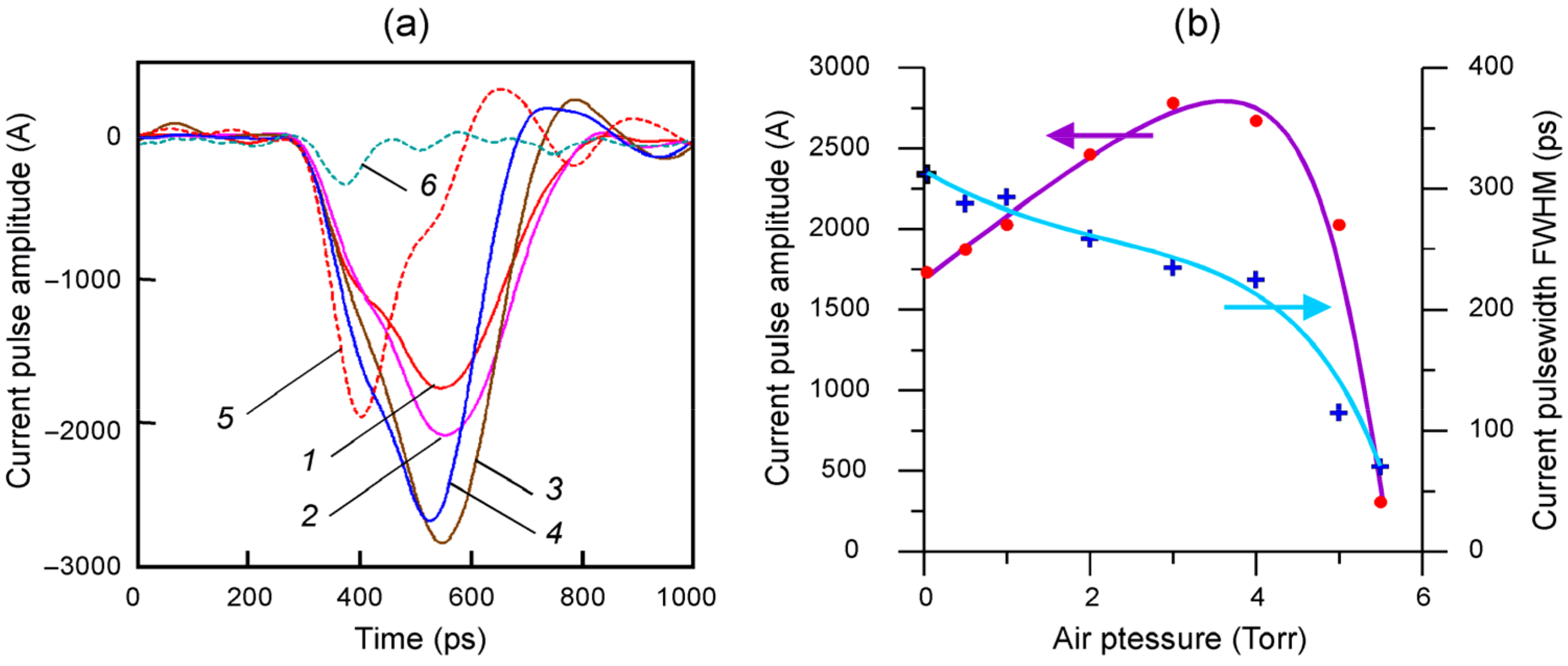
Figure 9a presents a series of the beam current pulses recorded by a collector probe in the pressure range of 3 × 10⁻²–5.5 Torr. The amplitudes (modulo) and durations (FWHM) of these pulses versus pressure are shown in Figure 9b. For the pressure p < 10−1 Torr, the amplitude (≈1700 A) and duration (≈300 ps, FWHM) of the EEE current (1 in Figure 9a) does not actually change. In this case, the beam current pulse from the collector probe sufficiently matches the current envelope in the load obtained by the DTDR method. The amplitude difference was ≤10%.
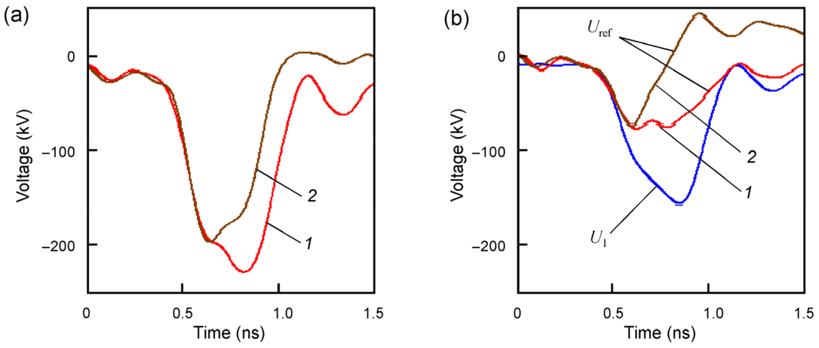
At p > 0.5 Torr, the current amplitude begins to increase and reaches the maximum of ≈2800 A at p = 3 Torr. In this case, the pulse at the cathode (2 in Figure 10a) decreases in amplitude and shortens: the trailing edge is cut off. However, its duration remains in the range of hundreds of picoseconds. The reflected pulse Uref on the reflectogram (2 in Figure 10b) changes polarity with some delay. That is, ionization processes are activated in a gas. A further increase in the pressure p > 3 Torr leads to the rapid decrease both in amplitude and duration of the beam current (4 → 5 → 6 in Figure 9a), and there was no current at p > 6 Torr. Judging by the reflectograms, in the latter case, distributed breakdowns occurred in the CTL when a supply pulse was delivered to the cathode. For this, for example, at p = 760 Torr, amplitudes Uc exceeding (modulo) 155 kV with the pulse duration of >270 ps were sufficient, which was demonstrated earlier [65,80].

3.4. Estimation for the Threshold Pressure between the EEE and RAE Generation Modes

Under vacuum conditions ( p 0 ), the flow of fast electrons registered on the collector is obviously of the explosive-emission nature. For estimates, we assume that this flow is generated at a potential difference U = |Uc| = 100 kV; the interelectrode distance is D = 1 cm; the average field strength in the gap is U/D ≈ 100 kV/cm. With a gradual increase in gas pressure, an additional source of electrons will be secondary electrons arising from the ionization of gas molecules by electron impact. The threshold value of the reduced field for electron runaway is E cr / p 356   V / ( cm Torr ) for air/nitrogen [38], which, under conditions of an average field of ~100 kV/cm, provides the mass runaway of free electrons at pressures up to ~280 Torr. Thus, at the pressure values of interest to us (units of Torr), all secondary electrons will certainly run away, thereby enhancing the initial flow of fast electrons.
Let us determine the air pressure (p*) at which the contribution of secondary electrons becomes comparable to the contribution of primary explosive-emission electrons. The number of ionization events produced by one fast electron per unit length is given by the equation:
d N i d z = n σ i ,
where σ i is the ionization cross section; the variable z corresponds to the direction of the electron motion from the cathode (z = 0) towards the collector/anode (z = D); n is the gas concentration. Under the considered conditions of relatively low pressure, the energy loss of the primary electron due to inelastic interaction with gas molecules can be neglected, and its kinetic energy ε is determined by the potential difference passed by it. Then we have, for a homogeneous field:
ε ( z ) e U z / D ,
where e is the elementary charge.
As is known [81], the electron impact ionization cross section depends nonmonotonically on the electron energy ε . Its maximum value for air/nitrogen is σ max 3 10 16   cm 2 and corresponds to the energy ε max 110   eV . The largest contribution to the gas ionization is made by the part of the electron trajectory with ε > ε max . Here the cross section can be approximated as ( A 1 / ε ) ln A 2 ε [47] (pp. 22–30), or, for consistency with [81], as:
σ i ( ε ) σ max ε max ε ln 2.718 ε ε max ,
where 2.718 is the base of the natural logarithm. Substituting (2) and (3) into (1), we arrive at the ordinary differential equation with respect to the variable ε :
d N i d ε = n D σ max ε max e U ε ln 2.718 ε ε max .
Its integration over the entire path of the electron, 0 < z < D, taking into account that e U > > ε max , yields:
N i n D σ max ε max 2 e U ln 2 2.718 e U ε max .
The number of primary and secondary electrons becomes comparable at Ni = 1, i.e., when, due to the interaction of explosive-emission electrons with gas, the number of fast electrons doubles. Then, the corresponding threshold value of the gas concentration is given by the formula:
n 2 e U D σ max ε max ln 2 2.718 e U ε max .
For the conditions under consideration, this gives n 9.9 10 16   cm 3 (recall that under normal conditions the gas concentration is ~ 2.7 10 19   cm 3 ), which corresponds to the threshold pressure p* ≈ 2.8 Torr.
At 0 < p < p* (i.e., at pressures lower than ≈2.8 Torr), it can be assumed that explosive-emission electrons form the basis of the flow of fast electrons. With an increase in pressure within this interval, the fraction of secondary electrons arising due to the interaction of explosive-emission electrons with gas increases from 0 to ~50%. The “gas amplification” of the fast electron current is realized, which is in good agreement with the experimentally observed picture for pressures rising to 3 Torr; see Figure 9.
Let us now discuss what will happen with a further increase in pressure. At the threshold pressure p = p*, the scale at which the number of fast electrons doubles coincides with the interelectrode distance D. When the threshold is exceeded, i.e., for p > p*, this scale will be less than D. In such a situation, the role of secondary electrons in ionization processes becomes fundamentally important; an avalanche multiplication of fast (runaway) electrons will occur. Because this process is explosive (the number of electrons will grow exponentially), then even with a slight excess of the pressure p*, the nature of the electrons reaching the anode/collector will inevitably change. The overwhelming majority of electrons will become secondary, born due to impact ionization of air molecules. In such a situation, the high-current flow of explosive-emission electrons is no longer required to initiate ionization processes in the gas. A flow of FE electrons from the cathode, orders of magnitude less intense, will suffice. This will lead to a shift in the moment of generation of the flow of fast (runaway) electrons to earlier times; no time delay will be required for the initiation of EEE due to the Joule heating of the cathode material by the FE current. This is precisely the picture observed in experiments when the pressure changes from 3 to 5.5 Torr; see Figure 9. The picture typical for EEE changes to the picture typical for RAE generation: the peak of the current burst is recorded earlier; its leading edge becomes steeper; the duration and amplitude decrease. The character of the high-voltage pulse reflections from the load (Figure 10) indicates the formation of a sufficiently dense plasma as a result of effective gas ionization in the interelectrode gap.
Let us summarize our reasoning. At pressures p < p* ≈ 3 Torr, explosive-emission electrons form the basis of the flow of fast electrons. As the pressure approaches the threshold p*, the effect of “gas amplification” of the current becomes significant; secondary electrons arising as a result of impact gas ionization by primary electrons begin to play a noticeable role in the flow of fast electrons. At pressures p > p* ≈ 3 Torr, the role of ionization processes grows explosively. The flow of fast electrons at the anode can be interpreted as a result of the avalanche multiplication of RAEs in the gap, and the primary RAEs are no longer explosive-emission, but field-emission in nature. For pressures near the threshold p* (or n*) determined by Formula (4), the transition occurs from the EEE mode to the RAE generation mode.

4. Conclusions

For the first time, in a sub-nanosecond range of durations and a wide range of residual gas pressures, for two cathode materials (graphite or steel), the jet characteristic of a tubular electron beam and its azimuthal homogeneity determined by the discreteness of activated FE centers was investigated in detail. In the experiments with generation of runaway electron flows in gas, it was shown that when the voltage at the cathode increases at a rate of hundreds of kilovolts per nanosecond, activation of the FE centers on graphite occurs with a time spread of several picoseconds. In the vacuum mode of explosive electron emission, this makes it possible to form kiloampere electron beams with a sub-nanosecond current front and with a similarly low jitter.
The range of residual gas pressures in the accelerating diode (units of Torr) was determined, where the vacuum mechanism of explosive electron emission is supplemented by the effects of the gas ionization by runaway electrons. For pressure up to ≈3 Torr, this leads to an increase in the magnetized beam current. In this case, the duration of the current (hundreds of picoseconds) was found to be comparable to the regime in a high vacuum. With an increase in pressure to the region of >3 Torr, with a slight decrease in the amplitude, the steepness of the front increases (up to ≈25 kA/ns, 5 in Figure 9a) and the current pulse duration decreases to ≈100 ps due to the development of a subsequent breakdown in the accelerating gap with participation of RAEs. Then, with an increase in pressure to ≈5.5 Torr, a rapid decrease in both duration and amplitude of the electron flow occurs.
Thus, it was shown that the current of a high-current electron beam having a duration of hundreds of picoseconds can be significantly increased in the pressure range of several Torr, while maintaining a picosecond temporal emission stability and the front steepness, and without significant reduction in duration and amplitude of the voltage at the cathode. This provides opportunities for increasing the power of electron sub-terahertz SR generators with spatially developed electrodynamic systems.

Author Contributions

Conceptualization, writing—review and editing, G.M. and V.S.; investigation, methodology, V.R.; data curation, K.S.; investigation, S.S.; investigation, writing-original draft, N.Z.; investigation, project administration, writing-original draft, M.Y. All authors have read and agreed to the published version of the manuscript.

Funding

This research in the section, studying the transition of the EEE mechanism to the runaway of electrons in a weak vacuum, resulting in the beam current increase and stability of its emission instant, was funded by the Russian Science Foundation, grant number 21-19-00260.

Data Availability Statement

The data that support the results of presented research are available from the corresponding author upon a reasoned request.

Acknowledgments

The research was performed using the equipment of the Collective Use Center at the Institute of Electrophysics, UB RAS. The authors are grateful to the Electrophysics department of Ural Federal University for providing the possibility to perform tests and measurements using the Tektronix DPO73304D oscilloscope.

Conflicts of Interest

The authors declare no conflict of interest.

References

  1. Gold, S.H.; Nusinovich, G.S. Review of high-power microwave source research. Rev. Sci. Instrum. 1997, 68, 3945–3974. [Google Scholar] [CrossRef]
  2. Benford, J.; Swegle, J.A.; Schamiloglu, E. High Power Microwaves, 3rd ed.; CRC Press: Boca Raton, FL, USA, 2015. [Google Scholar]
  3. Afanas’ev, K.V.; Bykov, N.M.; Gubanov, V.P.; El’chaninov, A.A.; Klimov, A.I.; Korovin, S.D.; Rostov, V.V.; Stepchenko, A.S. A high-power periodic nanosecond pulse source of coherent 8-cm electromagnetic radiation. Tech. Phys. Lett. 2006, 32, 925–927. [Google Scholar] [CrossRef]
  4. Grishin, D.M.; Lyubutin, S.K.; Mesyats, G.A.; Rostov, V.V.; Rukin, S.N.; Slovikovsky, B.G.; Timoshenkov, S.P.; Ul’maskulov, M.R.; Sharypov, K.A.; Shpak, V.G.; et al. Generation of Gigawatt 10-GHz Pulses with Stable Phase. Tech. Phys. Lett. 2008, 34, 822–824. [Google Scholar] [CrossRef]
  5. Rostov, V.V.; Gunin, A.V.; Romanchenko, I.V.; Pedos, M.S.; Rukin, S.N.; Sharypov, K.A.; Shunailov, S.A.; Shpak, V.G.; Ul’masculov, M.R.; Yalandin, M.I. Relativistic Ka-band backward-wave oscillators with stable phase. Phys. Plasmas 2017, 24, 063111. [Google Scholar] [CrossRef]
  6. Pengvanich, P.; Lau, Y.Y.; Luginsland, J.W.; Gilgenbach, R.M.; Cruz, E.; Schamiloglu, E. Effects of frequency chirp on magnetron injection locking. Phys. Plasmas. 2008, 15, 073110. [Google Scholar] [CrossRef]
  7. Andreev, D.; Kuskov, A.; Schamiloglu, E. Review of the relativistic magnetron. Matter Radiat. Extremes 2019, 4, 067201. [Google Scholar] [CrossRef] [Green Version]
  8. Wu, Y.; Li, Z.H.; Xu, Z. Experimental study of an X-band phase-locked relativistic backward wave oscillator. Phys. Plasmas 2015, 22, 113102. [Google Scholar] [CrossRef]
  9. Teng, Y.; Song, W.; Sun, J.; Xiao, R.Z.; Song, Z.; Zhang, L.; Zhang, Z.; Zhang, L.; Zhang, Y.; Li, J.; et al. Phase locking of high power relativistic backward wave oscillator using priming effect. J. Appl. Phys. 2012, 111, 043303. [Google Scholar] [CrossRef]
  10. Nusinovich, G.S.; Sinitsyn, O.V.; Rogers, J.; Shkvarunets, A.G.; Carmel, Y. Phase locking in backward-wave oscillators with strong end reflections. Phys. Plasmas. 2007, 14, 053109. [Google Scholar] [CrossRef]
  11. Xiao, R.Z.; Deng, Y.; Shi, Y.; Yang, D. Phase stabilization of a relativistic backward wave oscillator by controlling the cathode characteristics for a slowly rising voltage pulse. J. Appl. Phys. 2019, 125, 173302. [Google Scholar] [CrossRef]
  12. Mesyats, G.A.; Ginzburg, N.S.; Golovanov, A.A.; Denisov, G.G.; Romanchenko, I.V.; Rostov, V.V.; Sharypov, K.A.; Shpak, V.G.; Shunailov, S.A.; Ulmaskulov, M.R.; et al. Phase-Imposing Initiation of Cherenkov Superradiance Emission by an Ultra-Short Seed Microwave Pulse. Phys. Rev. Lett. 2017, 118, 264801. [Google Scholar] [CrossRef]
  13. Bakunin, V.L.; Denisov, G.G.; Novozhilova, Y.V. Phase Locking of a Gyrotron with Low-Frequency Voltage and Current Fluctuations by an External Monochromatic Signal. Radiophys. Quantum Electron. 2020, 63, 392–402. [Google Scholar] [CrossRef]
  14. Bakunin, V.L.; Denisov, G.G.; Novozhilova, Y.V. Frequency and phase stabilization of a multimode gyrotron with megawatt power by an external signal. Tech. Phys. Lett. 2014, 40, 382–385. [Google Scholar] [CrossRef]
  15. Song, W.; Sun, J.; Shao, H.; Xiao, R.Z.; Chen, C.H.; Liu, G.Z. Inducing phase locking of multiple oscillators beyond the Adler’s condition. J. Appl. Phys. 2012, 111, 023302. [Google Scholar] [CrossRef]
  16. Shunailov, S.A.; Mesyats, G.A.; Romanchenko, I.V.; Rostov, V.V.; Sadykova, A.G.; Sharypov, K.A.; Shpak, V.G.; Ulmasculov, M.R.; Yalandin, M.I. Electromagnetic noise of a nanosecond magnetized high-current electron beam. J. Appl. Phys. 2019, 126, 164504. [Google Scholar] [CrossRef]
  17. Abubakirov, E.B.; Denisenko, A.N.; Konyushkov, A.P.; Soluyanov, E.I.; Yastrebov, V.V. Observation of Large-Scale Shot Noise in a High-Current Electron Beam. Tech. Phys. Lett. 2018, 44, 857–859. [Google Scholar] [CrossRef]
  18. Korovin, S.D.; Litvinov, E.A.; Mesyats, G.A.; Murzakaev, A.M.; Rostov, V.V.; Shpak, V.G.; Shunailov, S.A.; Yalandin, M.I. Experimental investigation of graphite explosive-emission cathodes operating in a periodic pulse regime. Tech. Phys. Lett. 2004, 30, 813–816. [Google Scholar] [CrossRef]
  19. Ginzburg, N.S.; Sergeev, A.S.; Zotova, I.V.; Novozhilova, Y.V.; Peskov, N.Y.; Konoplev, I.V.; Phelps, A.D.R.; Cross, A.W.; Cooke, S.J.; Aitken, P.; et al. Experimental observation of superradiance in millimeter-wave band. Nucl. Instrum. Methods Phys. Res. A 1997, 393, 352–355. [Google Scholar] [CrossRef] [Green Version]
  20. Grishin, D.M.; Gubanov, V.P.; Korovin, S.D.; Lyubutin, S.K.; Mesyats, G.A.; Nikiforov, A.V.; Rostov, V.V.; Rukin, S.N.; Slovikovskii, B.G.; Ul’maskulov, M. R et al. High-power subnanosecond 38-GHz microwave pulses generated at a repetition rate of up to 3.5 kHz. Tech. Phys. Lett. 2002, 28, 806–809. [Google Scholar] [CrossRef]
  21. Eltchaninov, A.A.; Korovin, S.D.; Mesyats, G.A.; Pegel, I.V.; Rostov, V.V.; Shpak, V.G.; Yalandin, M.I. Review of Studies of Superradiative Microwave Generation in X-Band and Ka-Band Relativistic BWO’s. IEEE Trans. Plasma Sci. 2004, 32, 1093–1099. [Google Scholar] [CrossRef]
  22. Rostov, V.V.; Romanchenko, I.V.; Pedos, M.S.; Rukin, S.N.; Sharypov, K.A.; Shpak, V.G.; Shunailov, S.A.; Ul’masculov, M.R.; Yalandin, M.I. Superradiant Ka-band Cherenkov oscillator with 2-GW peak power. Phys. Plasmas 2016, 23, 093103. [Google Scholar] [CrossRef]
  23. Rostov, V.V.; El’chaninov, A.A.; Klimov, A.I.; Konev, V.Y.; Romanchenko, I.V.; Sharypov, K.A.; Shunailov, S.A.; Ul’maskulov, M.R.; Yalandin, M.I. Phase Control in Parallel Channels of Shock-Excited Microwave Nanosecond Oscillators. IEEE Trans. Plasma Sci. 2013, 41, 2735–2741. [Google Scholar] [CrossRef]
  24. Rostov, V.V.; Elchaninov, A.A.; Romanchenko, I.V.; Shunailov, S.A.; Ul’maskulov, M.R.; Sharypov, K.A.; Shpak, V.G.; Rukin, S.N.; Yalandin, M.I. Two-Channel Generator of the 8-mm Wavelength Range for Radiation with Subgigawatt Power Level Pulses. Radiophys. Quantum Electron. 2014, 56, 475–493. [Google Scholar] [CrossRef]
  25. Xiao, R.; Wang, Y.; Deng, Y.; Bai, X.; Song, Z. Particle-in-Cell Demonstration of the Effect of Voltage Rise Time on Phase Synchronization in Two Parallel Relativistic Backward-Wave Oscillators. IEEE. Trans. Electron. Devices 2016, 63, 1317–1321. [Google Scholar] [CrossRef]
  26. Xiao, R.Z.; Deng, Y.Q.; Chen, C.H.; Shi, Y.C.; Sun, J. Generation of powerful microwave pulses by channel power summation of two X-band phase-locked relativistic backward wave oscillators. Phys. Plasmas 2018, 25, 033109. [Google Scholar] [CrossRef]
  27. Vikharev, A.; Ginzburg, N.; Kuzikov, S.; Zotova, I.; Yalandin, M. Generation of Powerful Subterahertz Superradiance Pulses for High-Gradient Acceleration of Charged Particles. EPJ Web Conf. 2018, 195, 01023. [Google Scholar] [CrossRef]
  28. Danilov, Y.; Ginzburg, N.; Zotova, I.; Yalandin, M. The use of microwave superradiance pulses for electron high-gradient acceleration in cylindrical waveguide with dielectric insertion. Pis’ma Zh. Tekh. Fiz. 2021, 47, 27–30. [Google Scholar] [CrossRef]
  29. Ginzburg, N.S.; Malkin, A.M.; Sergeev, A.S.; Zheleznov, I.V.; Zotova, I.V.; Zaslavsky, V.Y.; Boltachev, G.S.; Sharypov, K.A.; Shunailov, S.A.; Ul’masculov, M.R.; et al. Generation of Sub-Terahertz Superradiance Pulses Based on Excitation of a Surface Wave by Relativistic Electron Bunches Moving in Oversized Corrugated Waveguides. Phys. Rev. Lett. 2016, 117, 204801. [Google Scholar] [CrossRef]
  30. Ginzburg, N.S.; Zaslavsky, V.Y.; Malkin, A.M.; Sergeev, A.S.; Zotova, I.V.; Sharypov, K.A.; Shunailov, S.A.; Shpak, V.G.; Ul’masculov, M.R.; Yalandin, M.I. Generation of intense spatially coherent superradiant pulses in strongly oversized 2D periodical surface-wave structure. Appl. Phys. Lett. 2020, 127, 183505. [Google Scholar] [CrossRef]
  31. Rostov, V.V.; Gunin, A.V.; Tsygankov, R.V.; Romanchenko, I.V.; Yalandin, M.I. Two-wave Cherenkov Oscillator with Moderately Oversized Slow Wave Structure. IEEE Trans. Plasma Sci. 2018, 46, 33–42. [Google Scholar] [CrossRef]
  32. Li, S.F.; Duan, Z.Y.; Huang, H.; Chen, Z.F.; Liu, Z.B.; He, H.; Wang, Z.L.; Gong, Y.B. Oversized coaxial relativistic extended interaction oscillator with gigawatt-level output at Ka-band. Phys. Plasmas 2019, 26, 043107. [Google Scholar] [CrossRef]
  33. Teng, Y.; Cao, Y.; Song, Z.; Ye, H.; Shi, Y.; Chen, C.; Sun, J. A Kaband TM02 mode relativistic backward wave oscillator with cascaded resonators. Phys. Plasmas 2014, 21, 123108. [Google Scholar] [CrossRef]
  34. Belomytsev, S.Y.; Korovin, S.D.; Mesyats, G.A. Shielding effect in the high-current diodes. Pis’ma Zh. Tekh. Fiz. 1980, 6, 1089–1092. [Google Scholar]
  35. Dreicer, H. Electron and ion runaway in a fully ionized gas: II. Phys. Rev. 1960, 117, 329–342. [Google Scholar] [CrossRef]
  36. Gurevich, A.V. On the theory of runaway electrons. Sov. Phys. JETP 1961, 12, 904–912. [Google Scholar]
  37. Stankevich, Y.L.; Kalinin, V.G. Fast electrons and X-radiation in the initial stage of pulse spark discharge development in air. Dokl. Akad. Nauk SSSR 1967, 177, 72–73. [Google Scholar]
  38. Babich, L.P.; Loiko, T.V.; Tsukerman, V.A. High-voltage nanosecond discharge in a dense gas at a high overvoltage with runaway electrons. Sov. Phys. Usp. 1990, 33, 521–540. [Google Scholar] [CrossRef]
  39. Babich, L.P.; Becker, K.H.; Loiko, T.V. Luminescence From Minerals Excited by Subnanosecond Pulses of Runaway Electrons Generated in an Atmospheric-Pressure High-Voltage Discharge in Air. IEEE Trans. Plasma Sci. 2009, 37, 2261–2264. [Google Scholar] [CrossRef]
  40. Shao, T.; Zhang, C.; Niu, Z.; Yan, P.; Tarasenko, V.F.; Baksht, E.K.; Burahenko, A.G.; Shut’ko, Y.V. Diffuse discharge, runaway electron, and x-ray in atmospheric pressure air in an inhomogeneous electrical field in repetitive pulsed modes. Appl. Phys. Lett. 2011, 98, 021503. [Google Scholar] [CrossRef]
  41. Tarasenko, V.F.; Shpak, V.G.; Shunailov, S.A.; Yalandin, M.I.; Orlovskii, V.M.; Alekseev, S.B. Subnanosecond electron beams formed in a gas-filled diode. Tech. Phys. Lett. 2003, 29, 879–881. [Google Scholar] [CrossRef]
  42. Mesyats, G.A.; Yalandin, M.I.; Sharypov, K.A.; Shpak, V.G.; Shunailov, S.A. Generation of a Picosecond Runaway Electron Beam in a Gas Gap with a Nonuniform Field. IEEE Trans. Plasma Sci. 2008, 36, 2497–2504. [Google Scholar] [CrossRef]
  43. Mesyats, G.A.; Yalandin, M.I. On the Nature of Picosecond Runaway Electron Beams in Air. IEEE Trans. Plasma Sci. 2009, 37, 785–789. [Google Scholar] [CrossRef]
  44. Tarasenko, V.F.; Rybka, D.V.; Burachenko, A.G.; Lomaev, M.I.; Balzovsky, E.V. Measurement of extreme-short current pulse duration of runaway electron beam in atmospheric pressure air. Rev. Sci. Instrum. 2012, 83, 086106. [Google Scholar] [CrossRef]
  45. Yatom, S.; Shlapakovski, A.; Beilin, L.; Stambulchik, E.; Tskhai, S.; Krasik, Y.E. Recent studies on nanosecond-timescale pressurized gas discharges. Plasma Sources Sci. Technol. 2016, 25, 064001. [Google Scholar] [CrossRef]
  46. Gurevich, A.V.; Mesyats, G.A.; Zybin, K.P.; Yalandin, M.I.; Reutova, A.G.; Shpak, V.G.; Shunailov, S.A. Observation of the Avalanche of Runaway Electrons in Air in a Strong Electric Field. Phys. Rev. Lett. 2012, 109, 085002. [Google Scholar] [CrossRef]
  47. Korolev, Y.D.; Mesyats, G.A. Physics of Pulsed Breakdown in Gases; Nauka: Moscow, Russia, 1991. [Google Scholar]
  48. Tarasova, L.V.; Khudyakova, L.N.; Loiko, T.V.; Tsukerman, V.A. 1974 Runaway electrons and X-rays of nanosecond discharges in gases at pressures of 0.1-760 Torr. Sov. J. Tech. Phys. 1974, 44, 564–568. [Google Scholar]
  49. Mesyats, G.A. Explosion Electron Emission; URO-Press: Yekaterinburg, Russia, 1998. [Google Scholar]
  50. Oreshkin, E.V.; Barengolts, S.A.; Chaikovsky, S.A.; Oreshkin, V.I. Simulation of a runaway electron avalanche devel-oping in an atmospheric pressure air discharge. Phys. Plasmas 2015, 22, 123505. [Google Scholar] [CrossRef]
  51. Baranov, V.F. Dozimetry of Eletronic Radiation; Atomizdat: Moscow, Russia, 1974. [Google Scholar]
  52. Yalandin, M.I.; Reutova, A.G.; Sharypov, K.A.; Shpak, V.G.; Shunailov, S.A.; UImasculov, M.R.; Rostov, V.V.; Mesyats, G.A. Stability of Injection of a Subnanosecond High-Current Electron Beam and Dynamic Effects Within Its Risetime. IEEE Trans. Plasma Sci. 2010, 38, 2559–2564. [Google Scholar] [CrossRef]
  53. Sharypov, K.A.; Ul’masculov, M.R.; Shpak, V.G.; Shunailov, S.A.; Yalandin, M.I.; Mesyats, G.A.; Rostov, V.V.; Kolomiets, M.D. Current waveform reconstruction from an explosively emissive cathode at a subnanosecond voltage front. Rev. Sci. Instrum. 2014, 85, 125104. [Google Scholar] [CrossRef] [PubMed]
  54. Shpak, V.G.; Shunailov, S.A.; Yalandin, M.I.; Dyadkov, A.N. The RADAN SEF-303A, a small high-current pulsed power supply. Instrum. Exp. Tech. 1993, 36, 106–111. [Google Scholar]
  55. Yalandin, M.I.; Lyubutin, S.K.; Oulmascoulov, M.R.; Rukin, S.N.; Shpak, V.G.; Shunailov, S.A.; Slovikovsky, B.G. High peak power and high average power subnanosecond modulator operating at a repetition frequency of 3.5 kHz. IEEE Trans. Plasma Sci. 2002, 30, 1700–1704. [Google Scholar] [CrossRef]
  56. Mesyats, G.A.; Shpak, V.G.; Shunailov, S.A.; Yalandin, M.I. Desk-top subnanosecond pulser research, development and applications. In Proceedings of the SPIE International Symposium: Intense Microwave Pulses II, Los Angeles, CA, USA, 24–26 January 1994; Volume 2154, pp. 262–268. [Google Scholar] [CrossRef]
  57. Juttner, B.; Putchkarjov, V.F.; Rohrbech, W. Behavior of micropoints during high voltage vacuum discharges. In Proceedings of the VII Int. Symp. on Discharges and Electrical Insulation in Vacuum, Novosibirsk, USSR, August 1976; pp. 189–192. [Google Scholar]
  58. Yalandin, M.I.; Mesyats, G.A.; Rostov, V.V.; Sharypov, K.A.; Shpak, V.G.; Shunailov, S.A.; Ulmasculov, M.R. Suppression of shunting current in a magnetically insulated coaxial vacuum diode. Appl. Phys. Lett. 2015, 106, 233504. [Google Scholar] [CrossRef]
  59. Zubarev, N.M.; Yalandin, M.I.; Mesyats, G.A.; Barengolts, S.A.; Sadykova, A.G.; Sharypov, K.A.; Shpak, V.G.; Shunailov, S.A.; Zubareva, O.V. Experimental and theoretical investigations of the conditions for the generation of runaway electrons in a gas diode with a strongly nonuniform electric field. J. Phys. D Appl. Phys. 2018, 51, 284003. [Google Scholar] [CrossRef]
  60. Levko, D.; Yatom, S.; Krasik, Y.E. Particle-in-cell modeling of the nanosecond field emission driven discharge in pressurized hydrogen. J. Appl. Phys. 2018, 123, 083303. [Google Scholar] [CrossRef]
  61. Naidis, G.V.; Tarasenko, V.F.; Babaeva, N.Y.; Lomaev, M.I. Subnanosecond breakdown in high-pressure gases. Plasma Sources Sci. Technol. 2018, 27, 013001. [Google Scholar] [CrossRef]
  62. Beloplotov, D.V.; Lomaev, M.I.; Sorokin, D.A.; Tarasenko, V.F. Ionization Waves During the Subnanosecond Breakdown Initiated by Runaway Electrons in High-Pressure Nitrogen and Air. Russ. Physics, J. 2017, 60, 1308–1313. [Google Scholar] [CrossRef]
  63. Kozhevnikov, V.Y.; Kozyrev, A.V.; Semeniuk, N.S. Physical kinetics of electrons in a high-voltage pulsed high-pressure discharge with cylindrical geometry. Russ. Phys. J. 2017, 60, 1425–1436. [Google Scholar] [CrossRef]
  64. Mesyats, G.A.; Yalandin, M.I. Nanosecond volume discharge in air initiated by a picosecond runaway electron beam. Phys. Usp. 2019, 62, 699–703. [Google Scholar] [CrossRef]
  65. Sharypov, K.A.; Shunailov, S.A.; Yalandin, M.I.; Zubarev, N.M. Reflectometry of Picosecond Emission and Discharge Processes in a Gas-Filled High-Voltage Coaxial Line. IEEE Trans. Plasma Sci. 2021, 49, 2516–2523. [Google Scholar] [CrossRef]
  66. Elinson, M.I.; Vasil’ev, G.F. Autoelectronic Emission; Fizmatgiz: Moscow, Russia, 1958. [Google Scholar]
  67. Batrakov, A.V.; Proskurovsky, D.I.; Popov, S.A. Observation of the field emission from the melting zone occurring just before explosive electron emission. IEEE Trans. Dielectr. Electr. Insul. 1999, 6, 410–417. [Google Scholar] [CrossRef]
  68. Batrakov, A.V.; Pegel, I.V.; Proskurovskii, D.I. Limitation of the field emission current density by the space charge of the emitted electrons. Tech. Phys. Lett. 1999, 25, 454–455. [Google Scholar] [CrossRef]
  69. Belomyttsev, S.Y.; Romanchenko, I.V.; Ryzhov, V.V.; Shklyaev, V.A. Initial stage of gas discharge in an inhomogeneous electric field. Tech. Phys. Lett. 2008, 34, 367–369. [Google Scholar] [CrossRef]
  70. Mesyats, G.A.; Yalandin, M.I.; Zubarev, N.M.; Sadykova, A.G.; Sharypov, K.A.; Shpak, V.G.; Shunailov, S.A.; Ulmaskulov, M.R.; Zubareva, O.V.; Kozyrev, A.V.; et al. How short is the runaway electron flow in an air electrode gap? Appl. Phys. Lett. 2020, 116, 063501. [Google Scholar] [CrossRef]
  71. Batrakov, A.V.; Pegel, I.V.; Proskurovsky, D.I. On the screening of the electric field at the cathode surface by an electron space charge at intense field emission. IEEE Trans. Dielectr. Electr. Insul. 1999, 6, 436–440. [Google Scholar] [CrossRef]
  72. Tiunov, M.A.; Fomel, B.M.; Yakovlev, V.P. SAM—An Interactive Code for Electron Gun Evaluation; Tech. Rep. INP-89-159; INP: Novosibirsk, Russia, 1989. [Google Scholar]
  73. Korovin, S.D.; Pegel, I.V. Structure of a high-current relativistic electron beam formed in a coaxial magnetically insulated diode with an edge cathode. Zh. Tekh. Fisiki 1992, 62, 139–145. [Google Scholar]
  74. Belomyttsev, S.Y.; Rostov, V.V.; Romanchenko, I.V.; Shunailov, S.A.; Kolomiets, M.D.; Mesyats, G.A.; Sharypov, K.A.; Shpak, V.G.; Ulmaskulov, M.R.; Yalandin, M.I. Magnetically Insulated Coaxial Vacuum Diode with Partial Space-Charge-Limited Explosive Emission from Edge-Type Cathode. J. Appl. Phys. 2016, 119, 023304. [Google Scholar] [CrossRef]
  75. Belomyttsev, S.Y.; Korovin, S.D.; Pegel, I.V. Effect of the expanding explosive-emission centers plasma on the impedance of a high-current diode. IEEE Trans. Plasma Sci. 1999, 27, 1572–1577. [Google Scholar] [CrossRef]
  76. Askar’yan, G.A. New possibilities of particle acceleration to high energies. Proc. P.N. Lebedev Phys. Inst. (USSR) 1973, 66, 66–72. [Google Scholar]
  77. Mesyats, G.A.; Romanchenko, I.V.; Rostov, V.V.; Sadykova, A.G.; Sharypov, K.A.; Shpak, V.G.; Shunailov, S.A.; Ul’masculov, M.R.; Yalandin, M.I. Effect of a submicrosecond-advanced voltage pulse on the formation of a high-current electron beam in a magnetically-insulated coaxial diode. Phys. Plasmas 2018, 25, 103118. [Google Scholar] [CrossRef]
  78. Sadykova, A.G.; Shunailov, S.A.; Yalandin, M.I.; Gurevich, A.V.; Zybin, K.P.; Sadykov, A.F.; Kolomiets, M.D. Air gap breakdown on runaway electrons. Russ. Phys. J. 2014, 57, 269–273. [Google Scholar]
  79. Mesyats, G.A.; Pedos, M.S.; Rukin, S.N.; Rostov, V.V.; Romanchenko, I.V.; Sadykova, A.G.; Sharypov, K.A.; Shpak, V.G.; Shunailov, S.A.; Ul’masculov, M.R. Formation of 1.4 MeV runaway electron flows in air using a solid-state generator with 10 MV/ns voltage rise rate. Appl. Phys. Lett. 2018, 112, 163501. [Google Scholar] [CrossRef]
  80. Zubarev, N.M.; Kozhevnikov, V.Y.; Kozyrev, A.V.; Mesyats, G.A.; Semeniuk, N.S.; Sharypov, K.A.; Shunailov, S.A.; Yalandin, M.I. Mechanism and dynamics of picosecond radial breakdown of a gas-filled coaxial line. Plasma Sources Sci. Technol. 2020, 29, 125008. [Google Scholar] [CrossRef]
  81. Peterson, L.R.; Green, A.E.S. The relation between ionization yields, cross sections and loss functions. J. Phys. B At. Mol. Phys. 1968, 1, 1131–1140. [Google Scholar] [CrossRef]
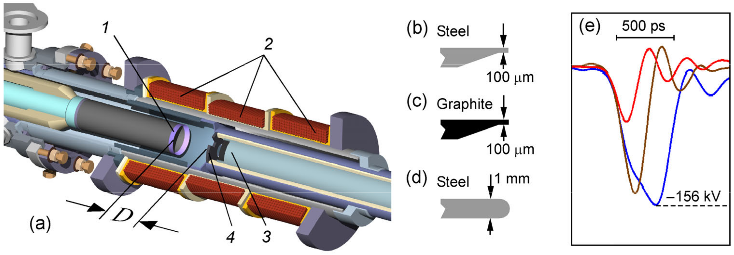
Figure 1. (a) The beam injector unit with a cold tubular cathode (1), pulse solenoid (2), and collector current probe (3) with segment collimator (4). (bd) Edge options for the tubular cathodes having an outer diameter of 22 mm. (e) Adjustable voltage pulses formed by a high-voltage generator to feed the cathode.
Electronics 11 00248 g001
Figure 2. (a) DTDR signal acquisition circuit and setting of the signals (b) used to separate Uref from the noise on the U1 signal tail and to measure the delay time τ1 of the load reflection in no-load mode.
Electronics 11 00248 g002
Figure 3. Typical oscillograms of incident (U1) and reflected (Uref) voltage pulses obtained in the modes of the MICD operation in vacuum (a) and at atmospheric pressure (b). 1; 2—graphite cathode; the gap D = 10 and 30 mm, respectively. 3; 4—steel cathode; the gap D = 10 and 30 mm, respectively.
Electronics 11 00248 g003
Figure 4. Diode configuration with 2-needle cathode; autograph of RAE jets.
Electronics 11 00248 g004
Figure 5. Autographs of magnetized tubular RAE beams obtained in atmospheric air at various values of accelerating gap D (10 and 30 mm), cathode voltages (63–132 kV), and magnetic fields (0.53–4.3 T) for graphite and steel cathodes having a diameter of 22 mm and emitting edge of ≈0.1 mm thick. The red circle shows the position of a fast-response current probe collector. Diameter of all photographs is 25 mm.
Electronics 11 00248 g005
Figure 6. Autographs of tubular beams in the MICD with graphite cathode and the gap D = 30 mm. (a) RAEs at B = 0.53 T; (b,c) vacuum EEE beam at B = 0.53 T and B = 2.1 T, respectively. (d) Calculation of electron trajectories for the case (b).
Electronics 11 00248 g006
Figure 7. Measurement of the RAE emission temporal stability at D = 30 mm. The collector has a diameter of 9 mm. Five consecutive pulses are presented. (a) Graphite cathode. The total beam current is 22 ± 4.5 A. The leading edge and duration (FWHM) of the current are ≈30 ps and ≈45 ps, respectively. Delayed RAE current pulse is shown for the time-of-flight estimation of the particle energy. (b) Increased emission time spread in the case of a steel cathode.
Electronics 11 00248 g007
Figure 8. Positions of the vacuum EEE beam current (2 kA) and the RAE flow at p = 760 Torr with an absolute time reference. Binding to the voltage pulse is conditional. Parameters: D = 10 mm; graphite cathode; collector has diameter of 25 mm; B = 2.1 T.
Electronics 11 00248 g008
Figure 9. (a) Pulses of the electron beam current from collector probe at different air pressures in the MICD: 1—3 × 10⁻² Torr; 2—1 Torr; 3—3 Torr; 4—4 Torr; 5—5 Torr; 6—5.5 Torr. Other parameters: graphite cathode; D = 10 mm; collector has diameter of 25 mm; B = 2.1 T. (b) The dependence of the amplitude (modulo) and duration (FWHM) of the beam current pulse in the pressure range.
Electronics 11 00248 g009
Figure 10. (a) The cathode voltage pulses registered using the DTDR method. (b) Supply pulse and the cathode reflections, time-aligned accounting for the delay τ1. Pressure: 1—3 × 10⁻² Torr; 2—3 Torr. Other parameters: graphite cathode; D = 10 mm; B = 2.1 T.
Electronics 11 00248 g010
Publisher’s Note: MDPI stays neutral with regard to jurisdictional claims in published maps and institutional affiliations.