Abstract
Due to numerous advantages, a neutral point clamped (NPC) inverter is a preferred choice for high-power applications and renewable technology. The reliability of the NPC inverter is a major concerning factor during the assessment of system performance as power semiconductor switches are vulnerable to abnormal conditions. Open-circuit (OC) switch faults are not as dangerous as short circuit (SC) faults but eventually have enough potential to cause cascaded failure to other components in the system and thus need to be supervised carefully. The OC faults result in a distortion of voltage and current signals in the NPC converter. Based on these signals, over the past few years, many efforts have been made to identify and localize the OC switch fault to the switch level in the NPC topology. In this paper, a review of different OC switch fault diagnostic methods is provided. Starting from the NPC inverter operation under healthy and faulty conditions, the various possible and unavailable switching states along with the deviation in pole voltage under different switch fault conditions is discussed. Then, based on the approach used for system-based fault detection, the OC fault detection methods are classified. The various OC methods are further discussed on the basis of signal, i.e., current, voltage or a combination of both signals used as a signature for fault detection. Emphasis is given to the principle involved, diagnostic variables utilized, the implementation approach and the diagnostic time required. Finally, the approaches are tabulated so as to provide a quick reference for NPC fault diagnostics.
1. Introduction
Depleting conventional energy resources and increasing energy demands of modern, industrial, and civilian society are responsible factors for the penetration of renewable energy resources in the conventional power system. Power electronic converters play a significant role in the confluence of renewable energy technology and conventional power systems, such as grid-connected wind turbine generation, grid-connected photovoltaics, and battery storage systems [1]. Power quality and harmonic distortions are deciding factors for system performance assessment. Multilevel inverter topology shows better performance on these fronts [2,3]. The diode clamped multilevel inverter is the most popular among multilevel inverter topology and is widely known as a neutral point clamped (NPC) inverter [4,5,6,7,8,9,10]. The NPC inverter offers a broad range of various medium voltage high power industrial applications [11,12].
Furthermore, timely fault investigation is the most required demand in important sectors such as healthcare, military, defense, aviation, electric traction, space technology, etc., where a slight margin of negligence can be disastrous [13,14]. Apart from this, fault diagnosis helps in the repair-related work of the converter, is useful in risk minimization, and helpful in the optimization of financial losses in case of failure. Since the NPC inverter has a higher number of power electronic switches compared to the conventional two-level inverter, power electronic semiconductor switches have serious failure issues as they are vulnerable to abnormal conditions. That is why the NPC inverter has more chances of failure, and therefore, reliability of the system is a major concerning factor [15,16,17]. Power quality issues such as voltage unbalance, system fluctuations, and harmonic distortions are the sources of sudden failures in power electronics converters. Such failures result in financial losses and sometimes even compromise the safety of the working personnel [18]. A common failure reason is power electronic switch faults. Switch faults are categorized as SC and OC faults [19,20,21]. SC switch faults can be hazardous and even fatal in some cases, but are monitored by a dedicated gate drive protection system and are easily detected due to the high short circuit current feature. Whereas OC switch faults, on the other hand, are not as dangerous as SC faults, but eventually have enough potential to cause cascaded failure to other components in the system and thus need to be supervised carefully [14,22,23]. Therefore, in recent decades, various OC faults have been suggested.
The main objective of the paper is to present the basic idea of different open-circuit switch fault diagnostic methods which have been used for NPC inverter topology. The main contributions are given as follows:
- Summary of the OC fault diagnostic methods for NPC.
- Comparison of the existing OC fault diagnostic schemes based on diagnostic variables, fault localization level, and fault diagnostic time.
2. Neutral Point Clamped Inverter under Normal and Open-Circuit Conditions
To explain the working of the various fault diagnostic approaches, the working of a single-phase three-level neutral point clamped inverter topology NPC is discussed in this section.
Figure 1 shows the circuit diagram for the single-phase three-level NPC inverter. Two series of connected capacitors, each having a voltage of , form the dc bus link of voltage . This dc bus link serves as an input to the neutral point clamped inverter. The midpoint of the two capacitors–dc bus link is considered a neutral point and it is available for circuit connection; unlike the two-level inverter where such a neutral point is unavailable. A zero-voltage level is possible due to this available neutral point in the case of the NPC inverter. The inverter output is taken across pole A and pole B. Output terminals can be connected to a load or an ac grid. There exist four active switches with anti-parallel diodes, also known as main switches and two clamping switches (diodes) in each leg of an NPC inverter. In Figure 2, , , and are main switches and and are clamping diodes. The clamping switches connect the neutral point to the inverter pole through the main switches as shown in Figure 2.
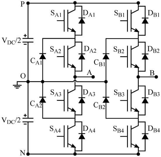
Figure 1.
Single-phase neutral point clamped inverter.
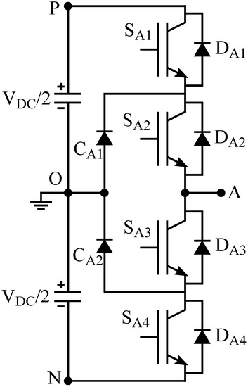
Figure 2.
A leg of the NPC inverter.
2.1. Analysis of NPC Inverter under Normal Conditions
Table 1 shows command signals given to the main switches and resulted in three-level pole voltages in corresponding switching states. Command signal 1 is used for switching on and 0 is used for switching off. Turning on switches and forms the switching state P, and in this, the corresponding pole voltage is . Switching state O is formed either by turning on or depending upon current direction and the corresponding pole voltage is . Firing on switches and forms the switching state N, and in this, the corresponding pole voltage is .

Table 1.
Switching states under normal operating conditions.
It is assumed that the current flowing from any one of the dc link terminals to the inverter pole is considered a positive direction of the current. Figure 3a,b, show the current paths for different switching states for the positive and negative current, respectively. Anti-parallel diodes conduct only for switching states N and P for the positive and negative direction of the current, respectively.

Figure 3.
Switching state circuits based on current direction for pole A. (a) Switching states P, O, N for i > 0. (b) Switching states P, O, N for i < 0.
2.2. Analysis of NPC Inverter under Open-Circuit Switch Fault
Due to the symmetry of the circuit, only phase A is analyzed. The direction of current from the inverter to the grid is assigned as a positive direction (i > 0). The OC fault can be considered a consequence of an unavailable switching state which is evident from Table 2. The unavailability of a switching state for a particular faulty switch is decided based on the faulty switch, the normal status of other switches, and the possible current path for the positive or negative current is depicted in Figure 4, Figure 5, Figure 6, Figure 7, Figure 8 and Figure 9.

Table 2.
Pole voltage deviation under faulty condition.
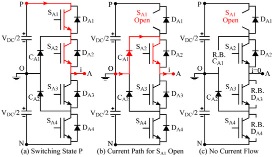
Figure 4.
Circuit diagram for open switch fault.
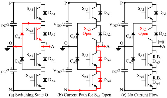
Figure 5.
Circuit diagram for open switch fault.
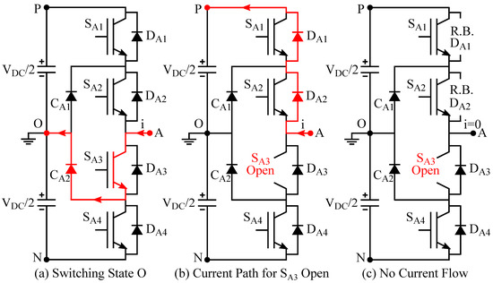
Figure 6.
Circuit diagram for open switch fault.
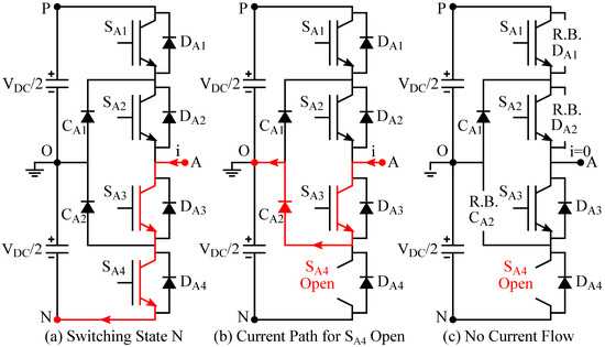
Figure 7.
Circuit diagram for open switch fault.
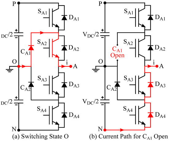
Figure 8.
OC switch fault.
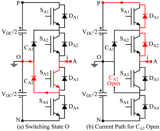
Figure 9.
OC switch fault.
3. Open-Circuit Switch Fault Diagnostic Methods for NPC Inverter
Figure 10 shows the general schematic of any fault diagnostic method. Whenever an OC fault occurs in any of the power electronic switches of the inverter, the current and voltage waveform shows abnormal distortions which are different from normal operating conditions. One or a combination of these system variables is considered a fault indicator. Fault diagnostic variables are determined using selected fault indicators. Fault diagnostic variables are treated as inputs for the fault detection scheme. However, there are certain possibilities of momentary system fluctuations that are not due to fault conditions. Such events can lead to misdiagnosis of fault conditions. This is avoided by incorporating threshold variables and time constraints. In addition to this, localization of the faulty switch is necessary to isolate the fault. Fault localization is performed using a fault detection signal along with the knowledge of fault diagnostic variables, thresholds, and constraints.
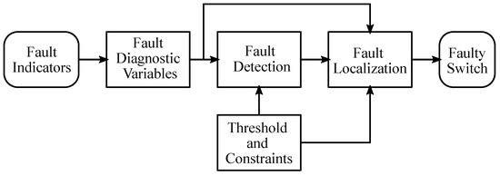
Figure 10.
General schematic of fault diagnostic method.
In this paper, the categorization of OC switch fault diagnostic methods is performed as (i) Hardware-Based Fault Detection; (ii) System-Based Fault Detection. In the former category, sensors are added to the gate driver circuit to measure the voltage and current of the switch which can be used to identify the fault in the switch. This method is not preferable because the number of sensors required will increase as the number of switches increases which in turn causes an increase in the cost and size of the system. The system-based fault detection method is based on the detection of fault using the current and voltage signals available for the control of the converter. In this signal, data such as current or voltage or both signals are directly used as fault signature information. The detailed classification of fault diagnostic methods for NPC inverter is shown in Figure 11. Due to the limited application of hardware-based fault detection, in this paper, we mainly focused on system-based fault detection methods which can be categorized as:
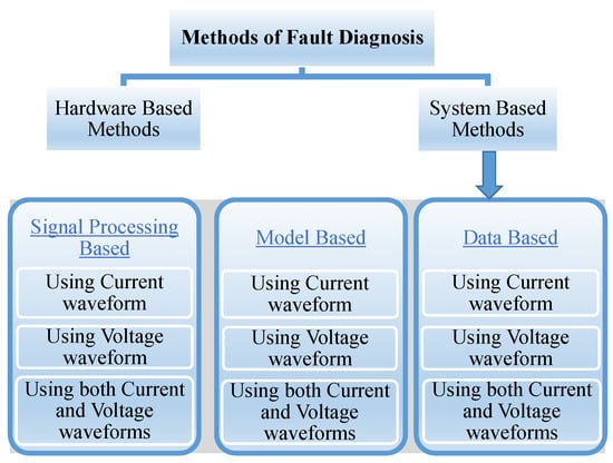
Figure 11.
Classification of fault diagnostic methods.
- Signal processing-based methods.
When the fault occurs in the inverter, the characteristics of the voltage and current waveforms get distorted. This change in the waveform carries the fault information which can be extracted using different signal processing techniques. The block diagram of the signal processing method is shown in Figure 12. The waveform required for fault feature extraction is sensed with the help of sensors, then the signal is segmented around the fault detection instant. After which the signal is processed in the time domain or frequency domain depending on the fault detection technique. From the processed data, the feature is extracted which can classify the fault.
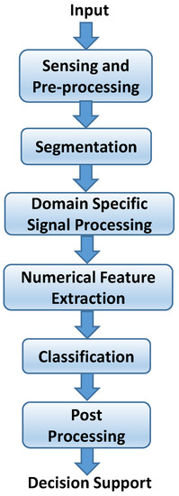
Figure 12.
Block diagram representation of signal processing-based fault diagnostic method.
- Model-based methods.
In this method, a model of the system developed from the analytic information is used for fault detection. The output of the real plant is compared with the output obtained from the model. If there is a fault, the estimated and actual parameters show variations. These signals which are called residual signals are analyzed and compared to identify the fault. The block diagram of the model-based fault detection method is shown in Figure 13. These methods are more accurate, but the accuracy highly depends on the accuracy of the model developed. Model predictive control-based fault diagnostic methods are also developed which can reduce the usage of additional sensors and minimize the computational burden.
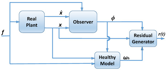
Figure 13.
Block diagram representation of model-based fault diagnosis method.
- Data-based fault diagnostic methods.
In data-based methods, no mathematical model is required which helps to overcome the limitations of model-based methods. This is based on the learning methods used for identification. This includes support vector machines, neural networks, fuzzy logic, and machine learning techniques. These methods have advantages such as faster detection, robust but the accuracy of the output depends on the data used. These methods require a huge amount of data for training. The block diagram of general steps involved in the data-based method is presented in Figure 14.

Figure 14.
Block diagram representation of data-based fault diagnosis method.
3.1. Signal Processing-Based Fault Diagnostic Methods
In this signal, data such as current or voltage or both signals are directly used as fault signature information. Current-based fault diagnostic methods [18,24,25,26,27,28,29,30,31,32,33,34,35,36,37,38] are more popular as they do not require any extra hardware. Some authors used voltage-based fault diagnostic methods [39,40,41,42,43,44,45,46]. Both current and voltage signals are used for the diagnosis in [47,48,49,50]. The following subsection discusses the various techniques used in the signal processing-based approach and a comparison of these techniques are given in Table 3.

Table 3.
Signal processing based fault diagnostic Methods.
3.1.1. Current-Based Methods
In [18], an OC fault detection technique for three-level three-phase NPC inverters is established. In this paper, the authors have presented a comparison method of fault diagnosis variables with threshold values. The diagnostic variable is defined as the ratio of the mean value of the phase current to the mean value of the absolute value of the phase current. The presented OC switch fault diagnosis comprises three steps: (i) computation of diagnostic variables; (ii) detection of faulty phase; (iii) pre-defined threshold and diagnostic variables comparison. By considering the knowledge of the diagnostic variable, the first faulty phase is identified. The false fault condition is avoided using slope calculation. Then, the diagnostic variable is compared with set threshold values to detect OC faults. Once a faulty leg is detected, the faulty switch is localized based on the value of the average current. A new localization variable is defined, and range durations are set corresponding to each switch so that the faulty switch can be localized accurately. This method can detect only single switch faults.
An OC fault diagnosis method for three-level NPC inverters based on current distortion in the output of the inverter is presented in [24]. In this paper, the inverter output current is considered as a function of switching states. OC faults in any one of the switches resulted in the distortion of the inverter output current. Distortions in the current waveform are based on the location of the faulty switch. When an OC fault occurs in external switches, either the positive or negative cycle of the inverter output current gets distorted. Similarly, when an OC fault occurs in internal switches, either the positive or negative cycle of the inverter output current gets suppressed. Calculation and comparison of positive and negative charges passing through each phase are performed. Based on this information, the location of the open-circuited faulty switch and the position of the leg of the three-phase inverter is deduced.
In [25], two OC switch fault detection methods based on a statistical analysis of the inverter output current are proposed. In the first method, current data points are defined as the first four statistical moments namely mean, variance, skewness, and kurtosis. Different fault duration cases for a particular open switch fault are considered. Plots of statistical moments are obtained for two different fault durations. When an OC fault occurs for a particular IGBT switch, depending upon the noise level, kurtosis and skewness show variations for fault durations only and not for health. With the increase in noise level, variations are not significant, and the accuracy of fault detection decreases as does the reliability. In the second method, a cumulative sum approach for current data samples has been used by the authors. For the cumulative sum approach, a threshold is set. Whenever a cumulative sum is higher than the threshold it is considered detection of the OC fault. In the presented methods, a no-fault localization scheme is proposed.
The current distortion in the inverter and rectifier of a back-to-back converter using NPC topology, which is caused by various open-switch faults, is analyzed in [26]. The authors have presented a fault diagnostic method based on current distortion analysis which is considered the fault indicator. In this method, the current is categorized into positive range, negative range and zero range. The time duration of the zero range and sign of current in the previous half cycle determines the location of the faulty pair of switches. The positive current sign and negative current sign determine the open switch fault in upper pair switches and in lower pair switches, respectively. The exact location of the faulty switch cannot be determined using this method but the method offers fault diagnostic ability against all power factors. An open-circuit fault in a grid-connected NPC inverter using phase current is proposed in [27]. Under healthy conditions, the normalized average value of the positive half cycle of the phase current and the negative half cycle current is equal. When the fault occurs, the phase current gets distorted which causes the change in the average positive and negative half cycle current which is used as the fault indicator. To localize the fault at the switch level, an under-excited reactive current is applied for a short period. For detection and localization, nearly two cycles are taken in this method.
In [28], distorted phase current characteristics have been used by authors to detect open-circuit switch faults in main switches as well as clamping diodes. Each phase can be divided into two groups. For example, in phase A, group 1 consists of two upper switches and a diode. Similarly, group 2 consists of two lower switches and a diode. Under the normal condition, the average of the phase current is zero. When an open-circuit fault occurs in group 1 of a particular phase, the positive phase current gets distorted and the average current of that phase only becomes negative while for others it is positive. Similarly, when an open-circuit fault occurs in group 2, the negative phase current gets distorted and the average current of that phase becomes positive while for others it is negative. In the faulty group, from the nature of the phase current flow (i.e., current flows for open-circuit clamping diode fault and no current flows for open-circuit fault in IGBT switches), the faulty component is located. Between IGBT switches, the faulty IGBT switch is located based on the possibility of a particular switching state during under excited reactive current injection for a short time.
The average current Park vector approach to detect open-circuit switch faults is proposed in [29]. In this method, two diagnostic variables are used: (i) error between the absolute average value of normalized phase currents under normal operation and absolute normalized phase current; and (ii) average current Park’s vector. Park vector components, id and iq, are obtained by converting the three-phase current of the inverter into a dq reference frame. In the case of an open switch fault, the error signal in the faulty phase becomes positive and the average current Park’s vector becomes nonzero. The faulty phase is located by the sign of the error signal as the error signal is positive for only the faulty phase and is otherwise negative. Based on the value of the error signal and the average current Park’s vector, a fault signature table is prepared for the combination of faulty switch pairs. With this information, the localization of the faulty switch is established. In this method, the double switch fault condition is also considered. A diagnosis method based on the average current Park transform vector is proposed in [30], which can accurately locate single switch faults. However, the method depends on the space vector pulse width modulation (SVPWM) and the load level, which has certain limitations.
In [31], authors have proposed the current pattern analysis method for open-circuit switch fault detection of main as well as clamping switches for the hybrid active NPC inverter. In this method, three-phase currents are transformed to the dq reference frame and the radius of the current pattern is determined using dq currents. In normal conditions, the locus of dq currents is a circle and when an open-circuit fault occurs, the current locus gets distorted due to the unavailability of certain switching states. The current pattern angle is determined for fault localization. Based on the current pattern angle, it is possible to distinguish between the upper three switch pairs and the lower three switch pairs in any leg. Using zero switching states, the injection of a reactive current for a short duration and if the phase current flows in the positive or negative direction, a faulty switch is uniquely represented in the upper as well as in the lower pair of switches. An open-circuit fault diagnosis method for a three-level NPC inverter based on the instantaneous frequency (IF) of the phase current is proposed in [32]. Hilbert transform is used to estimate the instantaneous frequency of the three-phase currents measured. This information helps to identify the faulty phase. The faulty switch is located from the average value of the normalized current.
The current pattern analysis method to detect open-circuit switch faults in main switches, as well as clamping switches, is extended to the hybrid active NPC inverter in [33]. For fault localization purposes, a current pattern is investigated for its radius and angle. Complete 360 degrees are divided into six ranges; based on the current pattern angle value, radius fluctuations and switching states, all switches in the inverter circuit are uniquely localized.
An open-switch fault detection of NPC inverters using output current is discussed in [34]. From the knowledge of switching states and output normalized average currents, the faulty leg can be identified. The normalized current is used to make the fault detection variable independent of the load variations. The diagnostic variables which are defined based on the fault current are then compared with the threshold value to identify the faulty switch.
The authors in [35,36] suggested an OC fault diagnostic and tolerance control approach for grid-integrated hybrid ANPC inverters using optimal carrier-based pulse width modulation. The fault is detected using the dq current pattern obtained from the three-phase current using Park’s transformation. This approach is simple and can handle up to four switch faults in a single phase without the need for extra hardware.
DC bus neutral point current variations as a fault indicator to detect the open-circuit switch fault method are proposed in [37]. The DC bus neutral point current is considered a function of instantaneous three-phase currents and corresponding switching functions. An open switch fault leads to the unavailability of a certain switching state, thus, the fault condition is responsible for the changes in the neutral point current. Neutral point currents, along with three-phase currents and corresponding switching functions, are considered to have fault feature information and these are combinedly used to uniquely identify the location of a faulty switch. This method requires high-frequency bandwidth to sense dc bus neutral point currents in high-frequency applications.
3.1.2. Voltage-Based Methods
In [39], authors have presented an OC switch fault diagnostic method that is based on the concept of continuous pulse width modulation characteristics. In this method, fault detection is performed based on the pole voltage magnitude and its duration. Any voltage level other than desired voltage levels for a three-level inverter is considered an abnormal voltage. Pole voltage gets affected by the dc link voltage ripple and this is avoided by the use of distinct voltage levels using Zener diodes. The duration time of voltage levels is detected indirectly by integrator circuits. The output of the integrator is compared to fault reference which is decided based on the maximum sustainable duration time for each distinct level under the no-fault condition. The main aim of this method is to detect a fault rather than to localize it and hence no-fault localization is provided.
In [40], authors have used the analysis of inverter pole voltage to detect OC switch faults. In this method, pole voltage is measured and then compared with the expected pole voltage. Under no-fault conditions, these two voltages match. In the case of an open switch fault, pole voltage error is generated because of the difference between expected and measured pole voltages. This voltage error is a function of faulty phase line current, present switching state, and position of open-circuited IGBT switch. For fault localization, three diagnostic variables are defined: (i) normalized line voltage error variable; (ii) error location variable; and (iii) current state variable. The faulty phase is identified from the phase common to two affected normalized line voltage error variables. The error location variable decides the range of normalized line voltage variables caused due to different fault locations with the help of predefined threshold values. The current state variable is responsible for identifying different conditions of line current. Based on the possible combinations of these three diagnostic variables, the exact location of the faulty switch is identified.
When an OC fault occurs, pole voltage gets distorted or disappears during fault duration which leads to a power unbalance across switches that are used for the detection of a fault in [41]. The fault detection circuit comprises the voltage sensor, absolute value circuit, voltage level detector, integrator, and comparator. For each phase, the magnitude of pole voltage and its duration in a specific switching state is considered the fault signature information for the presented fault detection method. Once fault is detected, a reconfiguration strategy is also advised. In this method, a fault localization scheme is not provided.
In [42], authors have investigated inverter output voltage for open switch fault detection of seven-level hybrid active NPC inverter. In this method, fault diagnosis is performed based on (i) the error in the inverter output voltage during pre-fault and post-fault conditions and (ii) the polarity of the inverter output voltage. Under no-fault conditions, the error voltage is almost equal to zero except for the open switch fault condition. Depending upon the location of the faulty switch, different voltage levels are realized. Based on a different combination of desired and measured output voltage along with current direction, 22 up-counters are defined. Each counter is responsible to count specific errors. A decision is taken regarding the triggering of particular counters using the knowledge of inverter output current, desired output voltage and measured output voltage. Triggering a particular combination of counters is responsible for determining the exact location of an open-circuited faulty switch.
In [43], authors have demonstrated an OC switch fault diagnostic method for a four-level nested NPC inverter, based on an analysis of capacitor voltage ripple and inverter output voltage. Based on the switching states, the expected value of the output voltages are determined. These expected voltages are then compared with the measured output voltage. When there is no open switch fault, the measured output voltage is found to be the same as the expected output voltage. Voltage mismatch between expected and measured output voltage of the inverter is considered an open switch fault indicator. The faulty switch is localized on the basis of consideration of the direction of output current and capacitor voltage. If the output current is positive, then OC fault is considered to happen in one of the upper switches otherwise the fault is considered to happen in one of the lower switches. Based on the value of the voltage ripple of two capacitors, the exact location of the faulty switch is determined.
Fault detection and post-fault operation of a three-level flying capacitor NPC inverter are introduced in [44]. When the fault occurs, the control signal delivered by the PWM module and resultant leg voltage will be different. This is used to identify the fault. Once the fault is detected, the converter is reconfigured such that it can still deliver the power to the load with the existing healthy switch. This will improve the reliability of the converter.
In [45], the authors used three current sensors and six Rogowski coils in series with each clamping diode to identify the faulty transistors of the NPC inverter. To detect the open-circuit fault of switches, the current through each clamping diode and phase currents are needed. The main disadvantage of this method is the requirement of additional hardware and the cost of implementation is high.
The OC switch fault diagnostic method for a three-phase four-level active NPC inverter based on the analysis of the inverter output terminal voltage error is presented in [46]. In this method, output terminal voltage and inter half-bridge voltage are considered fault indicators. Inverter output terminal voltage and inter half-bridge voltage in each leg are functions of valid switching states, and hence, these two voltages are affected due to an open switch fault which is caused due to the absence of certain switching states. Reference values of corresponding voltages are determined before the initiation of fault localization. Voltage errors are calculated considering actual and reference voltage values. Three threshold boundaries are defined based on the value of voltage errors for both fault indicators. Based on the combination of integer values of fault indicators (+1, 0, −1); a faulty IGBT switch is uniquely localized.
3.1.3. Combined Current and Voltage-Based Methods
In [47], the authors have presented an OC switch fault diagnostic method for active NPC inverters, which uses both voltage and current information. In this method, three-phase currents, along with inverter pole voltage levels and switching states, are collectively considered fault indicators. During an open switch fault condition, in any fundamental cycle, there is a notable decrement in voltage level which results in the dc offset in the corresponding phase current. These changes in pole voltage and phase current are used to detect an open switch fault condition. A three-dimensional look-up table having (i) phase current, (ii) pole voltage, and (iii) switching state, is developed based on the fault condition of different switches. In each phase using this three-parameter information, a faulty switch is uniquely localized. If the fault is located in a clamping switch, then the corresponding phase leg is run as a common NPC. A two-phase operation with decreased power output is activated if the fault is located in the main switch. This method can be applied for five levels or higher levels of active NPC inverters as well as rectifiers.
Electromagnetic signatures of the dc bus are analyzed to detect the OC switch fault only in clamping diodes of a three-phase three-level NPC inverter as presented in [48]. In this, two methods of fault detection are demonstrated. Method 1 uses conducted emissions of the dc bus to detect the open clamping diode fault. An EMI filter connected between the dc source and dc side terminals of the inverter is used to obtain the image of common mode emissions. In normal conditions, the maximum voltage across the EMI filter resistor is within one volt. However, whenever an OC fault occurs for the clamping diode, the maximum voltage increases abnormally. Thus, amplitude variations in conducted emissions are considered a fault indicator. Method 2 uses radiated, i.e., near field emissions of dc bus to detect open clamping diode fault. A magnetic antenna is used to collect these near-field emissions. A Fast Fourier Transform is applied for voltage samples of the clamping diode. In normal conditions, there is no drop-in frequency of induced voltage across the antenna. Whenever an OC fault develops across a clamping diode, the frequency of the induced voltage suddenly drops, and a new low frequency is developed. Thus, frequency variations in radiated emissions of a dc bus are considered a fault indicator. For fault localization purposes, a fundamental period is divided into six equal time intervals for six clamping diodes. Whenever an OC fault occurs for any particular clamping diode, the corresponding voltage amplitude variations lie between specific time duration in one fundamental period.
3.2. Model Based Fault Diagnostic Methods
In this approach, mathematical models of the converter system are used for fault detection and an observer or state estimator is used to estimate unavailable current states [19,51,52,53,54,55,56,57,58,59,60]. The reliability of this method depends on the accuracy of the model. Model-based methods can be further categorized as equivalent to circuit-based methods and switch function-based methods. The details of different techniques used in model based method is discussed in the following section and a comparison is given in Table 4.

Table 4.
Model based fault diagnostic Methods.
3.2.1. Current-Based Methods
In [19], a model-based open-circuit fault diagnosis method for single-phase three-level NPC converters in electric railway applications is presented. The authors have used the mixed logical dynamic model to detect the OC switch fault of main IGBT switches as well as clamping diodes. A switching function and logical variable are defined for the connection of the pole to the inverter output voltage and current direction, respectively. For the mixed logical dynamic model in addition to control transitions, condition transitions are also considered, and based on this, a logical expression is formulated. OC fault conditions are analyzed using the residual approach. A residual is defined as the difference between actual grid current and estimated grid current. When the OC fault occurs, the rate of change of residual increases sharply and exceeds a threshold value. To avoid false fault detection, a counter is used which counts the duration for which the threshold is exceeded by the diagnostic variable. An OC switch fault is detected only if this duration is beyond the set control periods. Fault localization is performed using the knowledge of (i) the polarity of the diagnostic variable and (ii) additional applied switching states.
A sliding mode observer (SMO) based fault diagnostic method for a three-level three-phase NPC inverter is proposed in [51]. The output current signal of the inverter is used as the original data for fault diagnosis. In this paper, we first established the mixed logic dynamic model of the inverter by utilizing the current flow direction of the switch under normal and fault conditions and designed a new sliding mode observer to estimate the output current of the inverter under normal conditions. The difference between the actual current and estimated current is termed residual current and it is zero under a no-fault scenario. However, as and when an OC fault takes place, the estimated output inverter current deviates from the actual inverter output current and the residual current becomes nonzero. An OC fault is considered in the upper half leg for the positive residual current and in the lower half leg for the negative residual current. The exact location of the faulty switch is decided using residual current and threshold current. This method provides robustness to the modeling uncertainty and effect of unknown disturbances. In this method, fixing of the threshold is very crucial. The influence of error in parameter, sampling and unknown disturbances are considered to determine the threshold value.
In [52], a fault diagnostic method for detecting the open switch fault and current sensor fault using interval sliding mode observer [53] is proposed. In this method, a faulty phase detection variable and the adaptive threshold value are obtained from the current form factor of the estimated current and measured current using the Equations (1) and (2), respectively.
where T is the period of the current, and represent the estimated and measured current form factors. When the NPC inverter is operated under normal conditions, the variables and will be approximately equal to zero. When the fault occurs, this will be high which is used to detect the fault.
where,
After the detection of a fault, the fault location in the sensor or switch is identified by comparing the sum of the measured current and estimated current. If the fault occurs in the current sensor, these values will be different, which can be used to detect the current sensor fault. Now using the derivative of the phase current and power switch identification variable (defined in Equation (4)), a fault in the sensor can be detected. To detect the power switch fault, faulty bridge arm detection variables (, ) (defined in Equations (5) and (6)), which is used to identify the faulty switch.
where i and are measured current and estimated current, respectively.
The advantage of this method is that both the current sensor fault and switch fault can be detected and do not require additional hardware. However, the complexity of the method is medium and can detect a single switch fault only.
The current estimator technique to detect an OC switch fault of the main, as well as the clamping switches for NPC and active NPC inverters used in electric vehicular applications, is proposed in [54]. A current estimator is represented by a discrete first-order system. When a difference between the measured current and estimated current, also termed an error, surpasses a particular set of threshold values, a fault detection signal is initiated. To avoid misdiagnosis due to high current transients, a separate transient detection condition is also included. In this method, two fault localization approaches are presented: (i) fault localization using an injection of pulse patterns, which is used for standstill fault diagnosis; and (ii) fault localization using state vector modulation pattern, which is used for online fault diagnosis. This method takes a longer time to detect faulty half legs during low vehicle speeds.
3.2.2. Voltage-Based Methods
In [55], the authors have presented a voltage-based modeling method to detect open switch faults. In this, a voltage equation modeling approach is demonstrated which can be used to represent normal as well as faulty operation of the inverter. A switching state variable is defined which can take only binary values (0 for switch off and 1 for switch on) is used while formulating voltage equations. Presented voltage equations are investigated for specific fault conditions. The proposed voltage modeling is also applicable to higher-level inverters with minor modifications.
In [56], Ahmadi et al. have presented a logic-based failure mode analysis method to detect OC switch faults in main IGBT switches and clamping diodes for a single-phase five-level NPC inverter. In this, the magnitude of the terminal voltage error is considered a fault indicator. Using dc link voltage and switching pattern, the terminal voltage is estimated. The estimated terminal voltage is compared with the measured terminal voltage for OC fault detection. If the voltage error continues beyond the set time duration, it is considered an open switch fault case. A voltage quantifier and a counter are suggested to avoid false fault diagnosis. Using switching pattern modifications, the OC fault in external switches is identified whereas the OC fault in internal switches can be identified directly or based on switching pattern modification depending on the applied switching state. A faulty clamping diode is located by switching on either of the external switches depending on the current direction.
Model predictive control-based fault diagnostic method is used to detect OC switch fault in a single-phase five-level cascaded full bridge NPC inverter is proposed in [57]. In this, a change in capacitor voltages is considered fault signature information. In normal conditions, there is no change in the capacitor voltages of the inverter. However, in the case of open switch faults, the capacitor voltage gets changed. Capacitor voltages can be increasing or decreasing in nature. These abnormal changes in capacitor voltages are considered OC fault conditions. A count variable is assigned to every switch in a submodule of the cascaded inverter. First, switches are investigated for short circuit faults and are taken care of by gate drive circuits if required. In the case of no short circuit fault, only then switches are investigated for an OC fault. The fault is identified based on the direction of the inverter output current and capacitor voltage changes present. This method fails if a multiple switch fault happens and is under a light load.
3.2.3. Combined Current and Voltage-Based Methods
In [59], an open switch fault diagnostic method based on the concept of uniform modeling using the switching function approach is demonstrated. The developed model introduced by this method can represent the inverter in normal as well as OC faulty conditions. The uniform modeling method is developed with the help of the switching function approach. A switch function is defined as +1, 0, −1 representing three levels of voltage based on switching states. Thus, a three-level converter is simplified into a switch equivalent circuit. It is assumed that for every leg, there can be a maximum of two high command signals of IGBT switches simultaneously. Command signals for a leg of the converter are considered as 4-bit binary code representing the status of four switches in the leg. For example, 1100 represents that the upper two switches are on and the converter is in a +1 switching state. When only one bit of the command signal is high, it is considered a condition of the OC fault. A mathematical model for each component in the overall circuit is developed with the help of circuit topology and a uniform model of a leg of the converter. The mathematical models are solved using Euler’s method. Waveforms for different fault conditions are analyzed along with a brief explanation.
Switch faults in the NPC using line voltage deviation are presented in [61]. In this method, the line voltage is measured and compared with the estimated line current from the knowledge of switching states. Since there is no complex calculation or data processing involved this method is faster, but fault detection at the switch level is not discussed. By using the Baum–Welch algorithm for iterative training, and the Viterbi algorithm for fault identification, a hidden Markov model (HMM) is proposed in [62] for the fault identification of the NPC inverter. The authors compared the HMM with other pattern recognition methods such as support vector machines and back propagation neural networks. The number of iterations required and training time for the HMM is comparatively less and the accuracy of fault detection is higher. However, the calculation steps in this method are complex and accuracy depends on the model accuracy.
3.3. Data-Based Fault Diagnosis Methods
In this approach, fault indicator signals are pre-processed through neural network, support vector machines, and fuzzy algorithms to produce fault label [63,64,65,66,67,68,69,70,71,72,73,74,75,76,77,78,79,80,81,82,83,84,85,86,87]. Such methods can also diagnose multiple switch fault detection. Table 5 presents a comparative details of different techniques used in data based approach.

Table 5.
Data based fault diagnostic methods.
3.3.1. Current-Based Methods
Artificial Neural Network-based OC switch fault detection method for a three-level NPC inverter fed induction motor is presented in [63]. Such detection requires only the dc link current and motor currents to be measured for detecting and identifying a power switch in which a short circuit fault or OC fault has occurred. In this method, three-phase currents are transformed to the stationary reference frame to obtain the trajectory of the space vector. In normal conditions, the trajectory of the space vector is a circle of fixed radius. When an OC switch fault occurs, the space vector trajectory no longer remains circular in shape. It obtains an inclined direction based on the fault switch position. Transformed currents and the dc link current are treated as input to the Artificial Neural Network-based controller. Using this information, the controller outputs two signals, namely an open switch fault mode code and interlocked PWM signal. A fault mode is a single open switch fault condition. Based on the fault mode code, a faulty switch is uniquely localized. For this method, fault diagnostic ability varies with the variation of the modulation index.
In [64], the authors have used the self-recurrent wavelet neural network method to detect the OC switch fault for a five-phase three-level NPC inverter. Derivation of the Gaussian function is used to form the structure of the wavelet neural network. Next, the Gradient Descent method is used to determine the weighting vector. To train the weights of the wavelet neural network, adaptive learning rates are utilized. After that, the output phase currents of the inverter for all phases are estimated using a non-linear function. Estimated currents are compared with actual currents to determine residual functions for all phases, which are investigated at each time instant. If any of the residual functions surpasses a defined threshold, an open switch fault detection signal is issued. In this method, multiresolution wavelet analysis is used for fault signature extraction. The wavelet coefficients of the signal such as mean, standard deviation, kurtosis, energy, etc., are determined using wavelet analysis. An extracted fault signature vector, based on these coefficients, is used for constraint determination for a semi-supervised fuzzy clustering algorithm which is used to localize a faulty switch. KNN (k-Nearest Neighbors) is considered a simple supervised learning algorithm that is vastly used for classification purposes. It is based on the classification of data point neighbors where its basic concept is to select ‘k’ samples, selected randomly from the training data, maintaining the lowest space among closest neighbors of data under test. In [65], the authors used it to detect the open-circuit fault in the NPC inverter. The capacitor current and the switches current are used for extracting the fault feature which is processed using discrete wavelet transform. This method can detect the fault with higher accuracy compared to Artificial Neural Networks, Support Vector Machines and Decision Tree but the detection time is higher compared to other methods without using machine learning.
In [66], S-H Kim et al. have provided fault diagnostic methods for the main as well as clamping switches of hybrid active NPC inverters, based on the convolution neural network (CNN). In normal conditions, three-phase currents show a balanced waveform. Under an open switch fault condition, currents get distorted. The fault conditions for each open switch fault are analyzed and corresponding current data is collected for different current levels. Before feeding this data to CNN, two pre-processing tasks are performed: (i) current data is normalized to make the data samples independent of the current level, and (ii) current data samples having repetitive nature are grouped in one cycle for the learning purpose. These processed three-phase current data are treated as input to the CNN. There are 18 single switch fault modes (6 fault modes per phase) and one normal operation mode, which are set as class labels, and these 19 labels are treated as the output of CNN. The backpropagation method is used to train the neural network. CNN determines the probability for each fault mode label based on inputted current data and outputs the label which has the highest probability among other labels, and this output is the localization signal for the faulty switch.
A neural network-based fault classification of NPC inverter is discussed in [67]. A joint approximative diagonalization of eigenmatrix and independent component analysis algorithm is used for the fault classification which reduces the size of an input to the neural network and helps to reduce the training time of the neural network. There are fewer iterative steps required compared to wavelet analysis and FFT and accuracy are better [68]. In [69], a backpropagation neural network is used to identify the fault in the cascaded NPC inverter. The frequency spectrum of the DC side current is used for the extraction of fault features. Harmonics amplitude and phase of the current spectra are fed to the backpropagation neural network for fault classification. In this method, only one sensor is used which will improve the system reliability and reduce the cost.
In [70], a novel fault diagnosis approach based on knowledge-driven and data-driven data was presented for open-circuit faults in insulated-gate bipolar transistors of the NPC inverter. This proposed method can locate open-circuit faults of IGBTs in the NPC inverter under different loads. The intelligent algorithms are used to extract the fault features in the current signals which avoid the trouble of modeling. However, it requires a large number of fault samples for training. In addition, applying this method accurately and efficiently is an issue.
A Fast Fourier Transform-based fault diagnostic method for three-level NPC is proposed in [71]. Frequency spectra of the output line current waveform are obtained using Fast Fourier Transform. Faults in the switches produce significant changes in the line current which in turn produce additional frequency components in the spectrum, which is used as the feature for fault detection. Once the fault is detected the inverter is enabled to supply the power by operating as a two-level inverter which will improve the reliability of the system. There is no learning process involved in this method and the detection time is about 60 ms.
A novel 1-D convolution neural network (CNN) with stochastic gradient optimization method is proposed in [72]. When the fault occurs the output current gets distorted which is used as the parameter for the detection of fault. First, output current data is collected which is then segmented, grouped, and normalized. The dataset will be set as the input of the proposed CNN network shown in Figure 15. The network contains forward propagation (FP) and backward propagation (BP). Schematic of BP and FP is shown in the Figure 16 The convolution layer is described using the following Equation (7).
where and are the weight and bias, is the input, and is the output of the layer. The result is the sum of j feature maps and c channels.
where m, n, and a are the input size and the kernel size of corresponding layers.
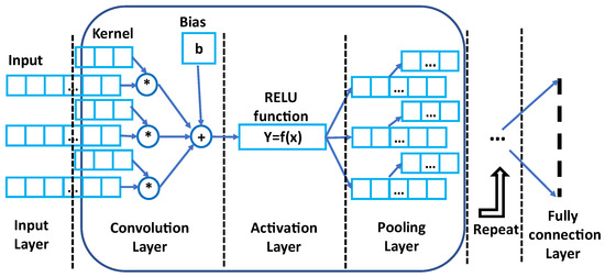
Figure 15.
Structure of 1-D CNN network.
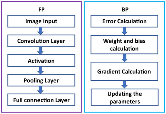
Figure 16.
Schematic of FP and BP processes.
Rectified linear unit (ReLU), is used as the activation function. After the activation layer, a pooling layer is used to improve the performance which is obtained using the relation Equation (8).
An improved Adamod Stochastic Gradient Optimization Method is used to update the weight of the neural network iteratively based on the training data. To improve the speed and efficiency of optimization, step size factors and limitation factors are introduced which will accelerate the convergence. These factors are chosen based on experience and improper selection will lead to oscillation and non-convergence.
An adaptive electrical period partition (AEPP) algorithm-based fault detection method is presented in [73]. The AEPP algorithm helps to precisely pick the electrical periods from the real-time current signals. The decomposition of the current signal is performed using maximal overlap DWT and the extracted low-frequency component is normalized using Park’s vector modulus (PVM) which is used as the input to the random forest (RF) model to detect the fault. The proposed RF technique yields the maximum fault diagnosis accuracy of 99.38%.
3.3.2. Voltage-Based Methods
In [74], the authors have demonstrated a fault diagnostic method-based neural network. This method focuses on atypical fault mode analysis. Atypical fault mode is a condition where an OC fault occurs in two switches on two cross bridge arms. Three-phase output voltages are considered to have fault signature information. These voltages are sampled and then transformed to the dq frame of reference to obtain dq voltages. A Fourier Transform is applied to the resultant dq voltage to obtain the amplitude and phase of available frequency components. The DC component, the aptitude of the fundamental, phase of the fundamental and second harmonic form the eight fault features of dq voltages. These act as inputs to the backpropagation NN (input layer of NN). All possible atypical fault modes are investigated, and 6-bit binary encoding is used to represent each unique fault mode. Six bits of binary code are obtained as the output of BPNN (output layer of NN). The momentum item algorithm and adaptive learning rate adjustment algorithm are used to train the NN. The hidden layer node number for NN is decided based on the expected training accuracy of NN. In this way, all possible fault modes are uniquely localized. In [75], open switch fault detection of NPC inverter based on multi-layer neural network is proposed. Bridge voltage is used for extracting the fault feature. In this method, principal component analysis was utilized to reduce the input size of the neural network. Classification performance and reliability of the method are good, but the accuracy depends on the amount of data available. For higher accuracy, a large amount of data is required.
In [76], Han et al. have presented a neural network-based algorithm for OC switch fault diagnosis for a single-phase three-level cascaded NPC inverter. Inverter pole voltage is considered to have fault signature information. In normal conditions, pole voltage has three voltage levels. The occurrence of an open switch fault leads to the unavailability of certain switching states which results in a change in voltage levels. To obtain fault signature information, Fast Fourier Transform (FFT) is used. Fault features obtained from the FFT of pole voltages are treated as the input layer of NN. A 9-bit binary vector is defined for each fault mode, in which the most significant bit stands for normal or faulty operation and the remaining 8-bits represent the on-off status of corresponding switches in that fault mode. This binary vector is treated as the output layer of NN. The gradient descent method is used to train the NN. Upon successful fault localization, a faulty module is bypassed using the presented reconfiguration strategy. In this method, double switch fault conditions are also included in fault modes. Backpropagation (BP) is widely used to train the neural network along with an optimization routine to improve accuracy. In [77], a backpropagation neural network with a genetic algorithm is used for fault detection. Bridge arm voltage is selected as the fault diagnosis signal. DC components with fundamentals and harmonics are fed as the input data for the BP neural network. Weights and thresholds of the BP neural network are optimized with the help of a genetic algorithm. This method is able to detect the individual switch fault effectively but the computational effort is high.
The sparse representation technique and support vector machine (SVM) method for OC switch fault diagnosis is proposed in [78]. Three phase voltage signals are sampled, and data points are collected. The fault signature is extracted by using the K-SVD algorithm. K-SVD is a mathematical algorithm used to generate a dictionary of sparse representation with the help of Singular Value Decomposition. Dictionary is a set of normalized vectors (also termed atoms) which are nothing but the sampled data points of the voltage signal. With the help of this algorithm, sparse representation coefficients of three-phase voltage signals and over complete dictionary are developed. Sparse representation coefficients are termed as the fault signature information of voltage signals. The OC fault is identified using a support vector machine. It is a statistics-based machine learning algorithm used to differentiate between two data samples. The output of the support vector machine is considered a fault type label and is used in fault localization. OC faults for a single switch as well as for two switches simultaneously are considered as different combinations of fault types. A label is assigned to each case of fault type. Sampled data points are categorized into testing and training samples. The support vector machine is edified with the help of training samples to generate a training model. Testing samples are used for vaticination. Vaticinated output and the actual output of the support vector machine are compared and analyzed to detect the fault type and hence the faulty switch is localized.
In [79], a method to detect the open-circuit fault of loads and semiconductors is discussed. The authors used discrete wavelet transform-based analysis for the classification of fault. The detection of fault is performed with the help of switching pulses and corresponding line voltages. When the fault occurs, the line voltage magnitude will be between the threshold voltage specified and can detect the fault. Once the fault is detected, fault classification algorithms will start working where multi-resolution analysis (MRA) of wavelet transform is used to extract the unique feature of each fault from the measured line voltage. Discrete wavelet packet transform-based fault feature extraction from the load voltage is presented in [80]. Load voltage is analyzed using discrete wavelet packet transform and the data obtained is artificial neural network for the classification and localization of the fault. The authors added a redundant leg to make the NPC inverter fault tolerant.
A stacked auto-encoder (SAE)-based fault detection method for NPC is proposed in [81]. SAE-based diagnosis method can extract more discriminative high-level features and has a better performance in fault diagnosis compared with the traditional machine learning methods [82]. Inverter bridge arm voltage is used for the fault feature extraction in this method. The amplitude spectrum of the bridge arm voltage is used as the input of the SAE network. For feature extraction and classification, a gravitational search algorithm is used. The accuracy of this method is better than the traditional BP neural network and support vector machine SVM diagnosis method and can detect multiple faults in the NPC inverter, but the computational complexity and data requirements are higher.
Wavelet analysis can be used to analyze the waveform and extract the feature that can be used for fault identification. Multi-resolution wavelet analysis and Bayesian classifier-based fault diagnosis methods are proposed in [83] to detect OC switch faults in main IGBT switches as well as clamping diodes of NPC inverter. Pole voltages are considered to have fault signature information. In the case of an open switch fault, the waveform of the three-level pole voltage gets changed. This leads to a change in energy in the various frequency components of pole voltage. The energy is determined using wavelet analysis in which pole voltages are sampled and then four orders Daubechies wavelet function is used to obtain wavelet coefficients and with the help of these, the energy of different frequency components is determined. The energy signature of a signal is used as an input vector for the Bayesian classifier. The Bayesian classifier is used to differentiate input sampled data into different classes of faulty switch conditions. The Bayesian classifier uses the probability density function along with prior probabilities to determine the posterior probability of different classes to identify the faulty switch. Noise levels in the signal can impact the fault localization accuracy of this method.
3.3.3. Combined Current and Voltage-Based Methods
In [84], Shen et al. have demonstrated a dual input convolution neural network (CNN)-based open switch fault diagnostic method. In this method, midpoint voltages, as well as three-phase currents of the NPC inverter, are considered signals for the extraction of fault information. Open switch fault is considered as a fault mode and all possible fault modes are encoded into a 12-bit Boolean vector representing the status of 12 switches in a three-phase three-level NPC inverter (0 for normal and 1 for OC). Such 12-bit codes are used as sample labels for CNN deep learning. The CNN diagnostic method is categorized into two parts, namely network training and network test. Using specific ratios, collected samples are divided into a training set and test set. Training set samples are provided to NN separately to achieve less error between the sample label and the corresponding sample label. Once the network is trained, testing set samples are also provided to NN separately to classify the output to the nearest sample label until the diagnosis ability is satisfied otherwise the process is repeated. Fault localization is performed using the dual input CNN model. Current information regarding the OC fault is extracted by the main CNN structure whereas the voltage information regarding the OC fault is extracted by the auxiliary CNN structure. Both these CNN structures are then combined using a fully connected network and fault mode mapping is performed which outputs the 12-bit fault mode Boolean code. Based on the status of bits and their position in code, open-circuited faulty switch or combination of switches are uniquely localized. Double switch fault conditions are also considered in this method.
Open-circuit fault detection with the help of combined model-based and data-processing based methods for single and multiple switches is proposed in [85]. A sliding mode PI observer is used to estimate the DC component of the fault profile and helps to detect the fault. Average line current data is used to extract the extra fault signature to localize the fault. In this method, both line current and grid voltages are used for fault identification. Even though this method is able to identify single and multiple faults, the computational complexity and fault detection time is higher. In [86], data-driven methods from machine learning are applied to select model-based residuals for increasing fault detection and isolation performance in the presence of uncertainties and disturbances in the residuals. Hybrid approaches merging model- and data-based methods have gained attention in recent years [87], to achieve better performance of fault detection and diagnosis systems.
The possibility of getting three or more switches under OC fault is very rare and thus not given much importance in the presented methods. Classifier-based methods are able to diagnose double switch OC faults. The majority of methods consider only single switch faults which is a normal fault scenario and use the current signal as fault signature information. This is because the majority of current-based fault detection methods offer ease of implementation and do not require additional hardware components, thus providing a cost-effective solution compared to other methods.
4. Conclusions
Neutral point clamped inverters have been proven as a preferred choice in the current renewable technology and existing electric drive industry, compared to two-level inverters, on the basis of improved power quality and numerous advantages. At the same time, these inverters have high failure chances owing to a higher number of switches, and thus, from the reliability point of view, proper fault diagnosis is of utmost importance. This paper presents a brief summary of available OC switch fault diagnostic methods used for neutral point clamped inverters. Table 3, Table 4 and Table 5 show the comparison of these diagnostic methods. The probability of getting three switches under OC fault is very rare and thus not given much importance in the presented methods. Classifier-based methods are able to diagnose double switch OC faults. The majority of methods consider only single switch faults which is a normal fault scenario and use the current signal as fault signature information. Neutral point clamped inverters have the potential to become a panacea to the majority of modern power system problems, provided that the reliability issue is properly addressed with appropriate fault diagnosis and monitoring methods.
Author Contributions
The presented work was developed by the following contributions: Conceptualization, M.R.M.K.P., M.N.N., Y.A.S., M.W.A. and H.M.; methodology, M.R.M.K.P., M.N.N., Y.A.S., M.W.A. and H.M.; software, M.R.M.K.P., M.N.N., Y.A.S., M.W.A. and H.M.; validation, M.R.M.K.P., M.N.N., Y.A.S., M.W.A. and H.M.; formal analysis, M.R.M.K.P., M.N.N., Y.A.S., M.W.A. and H.M.; investigation, M.R.M.K.P., M.N.N., Y.A.S., M.W.A. and H.M.; resources, M.R.M.K.P., M.N.N., Y.A.S., M.W.A. and H.M.; data curation, M.R.M.K.P., M.N.N., Y.A.S., M.W.A. and H.M.; writing—original draft preparation, M.R.M.K.P., M.N.N., Y.A.S. and M.W.A.; writing—review and editing, M.R.M.K.P., M.N.N., Y.A.S., M.W.A. and H.M.; visualization, M.R.M.K.P., M.N.N., Y.A.S., M.W.A. and H.M.; supervision, M.W.A. and H.M.; project administration, H.M. and M.W.A.; funding acquisition, M.W.A. and H.M. All authors have read and agreed to the published version of the manuscript.
Funding
This work was supported by the Science and Engineering Research Board, Government of India, under Project Number SRG/2021/001834.
Institutional Review Board Statement
Not applicable.
Informed Consent Statement
Not applicable.
Data Availability Statement
Not applicable.
Acknowledgments
The authors would like to acknowledge the support from Universiti Teknologi Malaysia (UTM), Johor Bahru 81310, Malaysia; and support from Intelligent Prognostic Private Limited Delhi, India Researcher’s Supporting Project (Project no. XX-02/2022).
Conflicts of Interest
The authors declare no conflict of interest.
References
- Lee, K.B.; Lee, J.S. Reliability Improvement Technology for Power Converters; Springer: Berlin/Heidelberg, Germany, 2017. [Google Scholar]
- Teichmann, R.; Bernet, S. A comparison of three-level converters versus two-level converters for low-voltage drives, traction, and utility applications. IEEE Trans. Ind. Appl. 2005, 41, 855–865. [Google Scholar] [CrossRef]
- Rodriguez, J.; Lai, J.S.; Peng, F.Z. Multilevel inverters: A survey of topologies, controls, and applications. IEEE Trans. Ind. Electron. 2002, 49, 724–738. [Google Scholar] [CrossRef]
- Gautam, S.P.; Kumar, L.; Gupta, S.; Agrawal, N. A single-phase five-level inverter topology with switch fault-tolerance capabilities. IEEE Trans. Ind. Electron. 2016, 64, 2004–2014. [Google Scholar] [CrossRef]
- Lee, J.S.; Kwak, R.; Lee, K.B. Novel Discontinuous PWM Method for a Single-Phase Three-Level Neutral Point Clamped Inverter With Efficiency Improvement and Harmonic Reduction. IEEE Trans. Power Electron. 2018, 33, 9253–9266. [Google Scholar] [CrossRef]
- Wang, H.; Liserre, M.; Blaabjerg, F.; de Place Rimmen, P.; Jacobsen, J.B.; Kvisgaard, T.; Landkildehus, J. Transitioning to physics-of-failure as a reliability driver in power electronics. IEEE J. Emerg. Sel. Top. Power Electron. 2013, 2, 97–114. [Google Scholar] [CrossRef]
- Zhang, L.; Sun, K.; Feng, L.; Wu, H.; Xing, Y. A Family of Neutral Point Clamped Full-Bridge Topologies for Transformerless Photovoltaic Grid-Tied Inverters. IEEE Trans. Power Electron. 2013, 28, 730–739. [Google Scholar] [CrossRef]
- Chen, A.; He, X. Research on Hybrid-Clamped Multilevel-Inverter Topologies. IEEE Trans. Ind. Electron. 2006, 53, 1898–1907. [Google Scholar] [CrossRef]
- Beniwal, N.; Tafti, H.D.; Farivar, G.G.; Ceballos, S.; Pou, J.; Blaabjerg, F. A Control Strategy for Dual-Input Neutral-Point-Clamped Inverter-Based Grid-Connected Photovoltaic System. IEEE Trans. Power Electron. 2021, 36, 9743–9757. [Google Scholar] [CrossRef]
- Wu, B.; Narimani, M. Diode-Clamped Multilevel Inverters. In High-Power Converters and AC Drives; John Wiley & Sons: Hoboken, NJ, USA, 2017; pp. 143–183. [Google Scholar] [CrossRef]
- Gupta, K.K.; Ranjan, A.; Bhatnagar, P.; Sahu, L.K.; Jain, S. Multilevel inverter topologies with reduced device count: A review. IEEE Trans. Power Electron. 2015, 31, 135–151. [Google Scholar] [CrossRef]
- Nabae, A.; Takahashi, I.; Akagi, H. A New Neutral-Point-Clamped PWM Inverter. IEEE Trans. Ind. Appl. 1981, IA-17, 518–523. [Google Scholar] [CrossRef]
- Di Tommaso, A.; Genduso, F.; Miceli, R.; Galluzzo, G.R. A review of multiple faults diagnosis methods in voltage source inverters. In Proceedings of the 2015 International Conference on Renewable Energy Research and Applications (ICRERA), Palermo, Italy, 22–25 November 2015; pp. 1376–1381. [Google Scholar]
- Yang, S.; Xiang, D.; Bryant, A.; Mawby, P.; Ran, L.; Tavner, P. Condition Monitoring for Device Reliability in Power Electronic Converters: A Review. Power Electron. IEEE Trans. 2010, 25, 2734–2752. [Google Scholar] [CrossRef]
- Choi, U.M.; Jeong, H.G.; Lee, K.B.; Blaabjerg, F. Method for detecting an open-switch fault in a grid-connected NPC inverter system. IEEE Trans. Power Electron. 2011, 27, 2726–2739. [Google Scholar] [CrossRef]
- Yang, S.; Bryant, A.; Mawby, P.; Xiang, D.; Ran, L.; Tavner, P. An industry-based survey of reliability in power electronic converters. IEEE Trans. Ind. Appl. 2011, 47, 1441–1451. [Google Scholar] [CrossRef]
- Wang, F.; Lai, R.; Yuan, X.; Luo, F.; Burgos, R.; Boroyevich, D. Failure-Mode Analysis and Protection of Three-Level Neutral-Point-Clamped PWM Voltage Source Converters. IEEE Trans. Ind. Appl. 2010, 46, 866–874. [Google Scholar] [CrossRef]
- Patel, K.; Borole, S.; Manikandan, R.; Singh, R.R. Short Circuit and Open Circuit Fault Identification Strategy for 3-Level Neutral Point Clamped Inverter. In Proceedings of the 2021 Innovations in Power and Advanced Computing Technologies (i-PACT), Kuala Lumpur, Malaysia, 27–29 November 2021; pp. 1–6. [Google Scholar]
- Ge, X.; Pu, J.; Gou, B.; Liu, Y.C. An open-circuit fault diagnosis approach for single-phase three-level neutral-point-clamped converters. IEEE Trans. Power Electron. 2017, 33, 2559–2570. [Google Scholar] [CrossRef]
- An, Q.T.; Sun, L.Z.; Zhao, K.; Sun, L. Switching Function Model-Based Fast-Diagnostic Method of Open-Switch Faults in Inverters Without Sensors. IEEE Trans. Power Electron. 2011, 26, 119–126. [Google Scholar] [CrossRef]
- Kim, C.; Russell, B. Classification of faults and switching events by inductive reasoning and expert system methodology. IEEE Trans. Power Deliv. 1989, 4, 1631–1637. [Google Scholar] [CrossRef]
- Choi, J.H.; Kim, S.; Yoo, D.S.; Kim, K.H. A diagnostic method of simultaneous open-switch faults in inverter-fed linear induction motor drive for reliability enhancement. IEEE Trans. Ind. Electron. 2014, 62, 4065–4077. [Google Scholar] [CrossRef]
- Smet, V.; Forest, F.; Huselstein, J.J.; Richardeau, F.; Khatir, Z.; Lefebvre, S.; Berkani, M. Ageing and Failure Modes of IGBT Modules in High-Temperature Power Cycling. IEEE Trans. Ind. Electron. 2011, 58, 4931–4941. [Google Scholar] [CrossRef]
- Alili, A.; Al Ameri, A.; Camara, M.; Dakyo, B. Open-circuit fault detection method for Grid-side Three-level NPC Inverter. In Proceedings of the 2021 10th International Conference on Renewable Energy Research and Application (ICRERA), Istanbul, Turkey, 26–29 September 2021; pp. 120–124. [Google Scholar]
- Baghli, M.; Delpha, C.; Diallo, D.; Hallouche, A. Three-Level Inverter Fault Detection and Diagnosis Using Current-Based Statistical Analysis. In Proceedings of the 2018 Prognostics and System Health Management Conference (PHM-Chongqing), Chongqing, China, 26–28 October 2018; pp. 686–691. [Google Scholar]
- Lee, J.S.; Lee, K.B.; Blaabjerg, F. Open-switch fault detection method of a back-to-back converter using NPC topology for wind turbine systems. IEEE Trans. Ind. Appl. 2014, 51, 325–335. [Google Scholar] [CrossRef]
- Choi, U.M.; Blaabjerg, F.; Lee, J.S.; Lee, K.B. Open-circuit fault diagnosis for a grid-connected NPC inverter with unity Power Factor. In Proceedings of the 2015 IEEE Applied Power Electronics Conference and Exposition (APEC), Charlotte, NC, USA, 15–19 March 2015; pp. 213–220. [Google Scholar] [CrossRef]
- Choi, U.M.; Lee, J.S.; Blaabjerg, F.; Lee, K.B. Open-circuit fault diagnosis and fault-tolerant control for a grid-connected NPC inverter. IEEE Trans. Power Electron. 2015, 31, 7234–7247. [Google Scholar] [CrossRef]
- Sital-Dahone, M.; Saha, A.; Sozer, Y.; Mpanda, A. Multiple device open circuit fault diagnosis for neutral-point-clamped inverters. In Proceedings of the 2017 IEEE Applied Power Electronics Conference and Exposition (APEC), Tampa, FL, USA, 26–30 March 2017; pp. 2605–2609. [Google Scholar]
- Abadi, M.B.; Mendes, A.M.S.; Cruz, S.M.A. Three-level NPC inverter fault diagnosis by the Average Current Park’s Vector approach. In Proceedings of the 2012 XXth International Conference on Electrical Machines, Marseille, France, 2–5 September 2012; pp. 1893–1898. [Google Scholar] [CrossRef]
- Kwon, B.H.; Bae, K.C.; Kim, S.M.; Lee, K.B. Detecting Method for an Open-Switch Fault of SiC MOSFET and Si IGBT in Hybrid ANPC Inverter System. In Proceedings of the 2019 IEEE Energy Conversion Congress and Exposition (ECCE), Baltimore, MD, USA, 29 September–3 October 2019; pp. 2928–2932. [Google Scholar]
- Xu, S.; Wang, J.; Ma, M. Open-circuit fault diagnosis method for three-level neutral point clamped inverter based on instantaneous frequency of phase current. Energy Convers. Econ. 2020, 1, 264–271. [Google Scholar] [CrossRef]
- Kim, S.H.; Kim, S.M.; Lee, K.B. Open-Switch Fault Detection for Hybrid ANPC Inverter Based on Current Distortion. In Proceedings of the 2019 IEEE Student Conference on Electric Machines and Systems (SCEMS 2019), Busan, Korea, 1–3 November 2019; pp. 1–5. [Google Scholar]
- Bandar Abadi, M.; Mendes, A.; Cruz, S. A Real-Time Method for the Diagnosis of Multiple Switch Faults in NPC Inverters Based on Output Currents Analysis. J. Power Electron. 2016, 16, 1415–1425. [Google Scholar] [CrossRef]
- Kim, Y.J.; Kim, S.H.; Kim, S.M.; Lee, K.B. Open Fault Diagnosis and Tolerance Control for Grid-Connected Hybrid Active Neutral-Point- Clamped Inverters With Optimized Carrier-Based Pulse Width Modulation. IEEE Access 2020, 8, 145542–145551. [Google Scholar] [CrossRef]
- Azer, P.; Ouni, S.; Narimani, M. A Novel Fault-Tolerant Technique for Active-Neutral-Point-Clamped Inverter Using Carrier-Based PWM. IEEE Trans. Ind. Electron. 2020, 67, 1792–1803. [Google Scholar] [CrossRef]
- He, J.; Demerdash, N.A. An on-line diagnostic method for open-circuit switch faults in NPC multilevel converters. In Proceedings of the 2016 IEEE Energy Conversion Congress and Exposition (ECCE), Milwaukee, WI, USA, 18–22 September 2016; pp. 1–7. [Google Scholar]
- Fazio, P.; Maragliano, G.; Marchesoni, M.; Parodi, G. A new fault detection method for NPC converters. In Proceedings of the Proceedings of the 2011 14th European Conference on Power Electronics and Applications, Birmingham, UK, 30 August–1 September 2011; pp. 1–10. [Google Scholar]
- Kim, T.J.; Lee, W.C.; Hyun, D.S. Detection method for open-circuit fault in neutral-point-clamped inverter systems. IEEE Trans. Ind. Electron. 2009, 56, 2754–2763. [Google Scholar]
- Caseiro, L.M.; Mendes, A.M. Open-circuit fault diagnosis in neutral-point-clamped UPS inverters with no additional sensors. In Proceedings of the IECON 2015-41st Annual Conference of the IEEE Industrial Electronics Society, Yokohama, Japan, 9–12 November 2015; pp. 2463–2468. [Google Scholar]
- Lee, J.D.; Kim, T.J.; Lee, J.C.; Hyun, D.S. A novel fault detection of an open-switch fault in the NPC inverter system. In Proceedings of the IECON 2007-33rd Annual Conference of the IEEE Industrial Electronics Society, Taipei, Taiwan, 5–8 November 2007; pp. 1565–1569. [Google Scholar]
- Azimipanah, M.; Hassanifar, M.; Neyshabouri, Y. Open Circuit Fault Detection and Diagnosis for Seven-Level Hybrid Active Neutral Point Clamped (ANPC) Multilevel Inverter. In Proceedings of the 2021 29th Iranian Conference on Electrical Engineering (ICEE), Tehran, Iran, 18–20 May 2021; pp. 268–273. [Google Scholar]
- Hassanifar, M.; Shamouei-Milan, M.; Neyshabouri, Y.; Nazarpour, D.; Golshannavaz, S. Fast Detection and Localization of Open-Circuit Switch Faults in Nested Neutral Point Clamped (NNPC) Inverter. In Proceedings of the 2020 11th Power Electronics, Drive Systems, and Technologies Conference (PEDSTC), Tehran, Iran, 4–6 February 2020; pp. 1–6. [Google Scholar]
- Bennani-Ben Abdelghani, A.; Ben Abdelghani, H.; Richardeau, F.; Blaquière, J.M.; Mosser, F.; Slama-Belkhodja, I. Versatile Three-Level FC-NPC Converter With High Fault-Tolerance Capabilities: Switch Fault Detection and Isolation and Safe Postfault Operation. IEEE Trans. Ind. Electron. 2017, 64, 6453–6464. [Google Scholar] [CrossRef]
- Farnesi, S.; Fazio, P.; Marchesoni, M. A new fault tolerant NPC converter system for high power induction motor drives. In Proceedings of the 8th IEEE Symposium on Diagnostics for Electrical Machines, Power Electronics & Drives, Bologna, Italy, 5–8 September 2011; pp. 337–343. [Google Scholar] [CrossRef]
- Pribadi, J.; Lee, D.C. Open-Switch Fault Diagnosis in Four-Level Active Neutral-Point-Clamped Inverters. In Proceedings of the 2021 IEEE Energy Conversion Congress and Exposition (ECCE), Vancouver, BC, Canada, 10–14 October 2021; pp. 2576–2581. [Google Scholar]
- He, J.; Demerdash, N.A. Diagnosis of open-circuit switch faults in multilevel active-NPC (ANPC) inverters. In Proceedings of the 2014 IEEE Transportation Electrification Conference and Expo (ITEC), Dearborn, MI, USA, 15–18 June 2014; pp. 1–6. [Google Scholar]
- Abari, I.; Lahouar, A.; Hamouda, M.; Slama, J.B.H.; Al-Haddad, K. Fault Detection Methods for Three-Level NPC Inverter Based on DC-Bus Electromagnetic Signatures. IEEE Trans. Ind. Electron. 2018, 65, 5224–5236. [Google Scholar] [CrossRef]
- Abari, I.; Hamouda, M.; Slama, J.B.H.; Al-Haddad, K. Single switch open-circuit fault detection for three-level npc inverter using conducted emissions signature. In Proceedings of the IECON 2018-44th Annual Conference of the IEEE Industrial Electronics Society, Washington, DC, USA, 21–23 October 2018; pp. 1489–1494. [Google Scholar]
- Ku, H.K.; Im, W.S.; Kim, J.M.; Suh, Y.S. Fault detection and tolerant control of 3-phase NPC active rectifier. In Proceedings of the 2012 IEEE Energy Conversion Congress and Exposition (ECCE), Raleigh, NC, USA, 15–20 September 2012; pp. 4519–4524. [Google Scholar] [CrossRef]
- Huang, W.; Xu, S.; Wang, J.; Dai, H.; Feng, L.; Chai, Y. A diagnosis method for open-circuit faults in NPC three-level inverters based on novel sliding mode observer. In Proceedings of the 2021 CAA Symposium on Fault Detection, Supervision, and Safety for Technical Processes (SAFEPROCESS), Chengdu, China, 17–18 December 2021; pp. 1–6. [Google Scholar]
- Xu, S.; Huang, W.; Wang, H.; Zheng, W.; Wang, J.; Chai, Y.; Ma, M. A Simultaneous Diagnosis Method for Power Switch and Current Sensor Faults in Grid-Connected Three-Level NPC Inverters. IEEE Trans. Power Electron. 2022, 1–15. [Google Scholar] [CrossRef]
- Oubabas, H.; Djennoune, S.; Bettayeb, M. Interval sliding mode observer design for linear and nonlinear systems. J. Process. Control. 2018, 959–1524. [Google Scholar] [CrossRef]
- Kersten, A.; Oberdieck, K.; Bubert, A.; Neubert, M.; Grunditz, E.A.; Thiringer, T.; De Doncker, R.W. Fault detection and localization for limp home functionality of three-level npc inverters with connected neutral point for electric vehicles. IEEE Trans. Transp. Electrif. 2019, 5, 416–432. [Google Scholar] [CrossRef]
- Rinsha, V.; Jagadan, G. Open Circuit Fault Detection in Neutral Point Clamped Inverter-A Voltage Model Based Analysis. In Proceedings of the 2020 IEEE Region 10 Symposium (TENSYMP), Dhaka, Bangladesh, 5–7 June 2020; pp. 74–77. [Google Scholar]
- Ahmadi, S.; Poure, P.; Saadate, S.; Khaburi, D.A. Open-switch and open-clamping diode fault diagnosis for single-phase five-level neutral-point-clamped inverters. IEEE J. Emerg. Sel. Top. Power Electron. 2020, 9, 4676–4686. [Google Scholar] [CrossRef]
- Wei, X.; Wang, H.; Luo, A.; He, Z.; Zhu, X.; Sun, R.; Chen, X. Parallel open-circuit fault diagnosis method of a cascaded full-bridge NPC inverter with model predictive control. IEEE Trans. Ind. Electron. 2020, 68, 10180–10192. [Google Scholar] [CrossRef]
- Ahmadi, S.; Poure, P.; Saadate, S.; Khaburi, D.A. A real-time fault diagnosis for neutral-point-clamped inverters based on failure-mode algorithm. IEEE Trans. Ind. Inform. 2020, 17, 1100–1110. [Google Scholar] [CrossRef]
- Peng, T.; Tao, H.; Yang, C.; Chen, Z.; Yang, C.; Gui, W.; Karimi, H.R. A uniform modeling method based on open-circuit faults analysis for NPC-three-level converter. IEEE Trans. Circuits Syst. II Express Briefs 2018, 66, 457–461. [Google Scholar] [CrossRef]
- Chen, W.; Bazzi, A.M. Model-Based Voltage Quality Analysis and Optimization in Post-Fault Reconfigured N-Level NPC Inverter. IEEE Trans. Power Electron. 2021, 36, 13706–13715. [Google Scholar] [CrossRef]
- Yang, B.; Chen, Q.; Tao, J.; Hou, S.; Zhao, L. Switch fault diagnosis and location of NPC three-level inverter based on line voltage deviation. In Proceedings of the 2022 IEEE 5th International Electrical and Energy Conference (CIEEC), Nangjing, China, 27–29 May 2022; pp. 3289–3293. [Google Scholar] [CrossRef]
- Zheng, H.; Wang, R.; Wang, Y.; Zhu, W. Fault diagnosis of photovoltaic inverters using hidden Markov model. In Proceedings of the 2017 36th Chinese Control Conference (CCC), Dalian, China, 26–28 July 2017; pp. 7290–7295. [Google Scholar] [CrossRef]
- Lee, H.H.; Dzung, P.Q.; Hoa, T.P.; Bac, N.X. Fault detection using ANN for Three-level NPC Inverter fed induction motor drive. In Proceedings of the TENCON 2010–2010 IEEE Region 10 Conference, Fukuoka, Japan, 21–24 November 2010; pp. 2148–2153. [Google Scholar]
- Torabi, N.; Naghavi, F.; Toliyat, H.A. Real-time fault isolation in multiphase multilevel NPC converters using active semi-supervised fuzzy clustering algorithm with pairwise constraints. In Proceedings of the 2017 IEEE International Electric Machines and Drives Conference (IEMDC), Miami, FL, USA, 21–24 May 2017; pp. 1–7. [Google Scholar]
- Achintya, P.; Kumar Sahu, L. Open Circuit Switch Fault Detection in Multilevel Inverter Topology using Machine Learning Techniques. In Proceedings of the 2020 IEEE 9th Power India International Conference (PIICON), Sonepat, India, 28 February–1 March 2020; pp. 1–6. [Google Scholar] [CrossRef]
- Kim, S.H.; Yoo, D.Y.; An, S.W.; Park, Y.S.; Lee, J.W.; Lee, K.B. Fault detection method using a convolution neural network for hybrid active neutral-point clamped inverters. IEEE Access 2020, 8, 140632–140642. [Google Scholar] [CrossRef]
- Hu, H.; Feng, F.; Wang, T. Open-circuit fault diagnosis of NPC inverter IGBT based on independent component analysis and neural network. Energy Rep. 2020, 6, 134–143. [Google Scholar] [CrossRef]
- Wan, X.; Hu, H.; Yu, Y.; Kang, L.; Zeng, F. Open-circuit Fault Diagnosis for Grid-connected NPC Inverter based on Independent Component Analysis and Neural Network. Telkomnika 2017, 15, 36. [Google Scholar] [CrossRef][Green Version]
- Zeng, L.; Han, P.; He, X. Fault Diagnosis of Cascaded NPC Inverter Based on Single Sensor. In Proceedings of the 2021 IEEE 16th Conference on Industrial Electronics and Applications (ICIEA), Chengdu, China, 1–4 August 2021; pp. 1924–1929. [Google Scholar] [CrossRef]
- Kou, L.; Liu, C.; Cai, G.; Zhou, J.; Yuan, Q.; Pang, S. Fault diagnosis for open-circuit faults in NPC inverter based on knowledge-driven and data-driven approach. IET Power Electron. 2020, 13, 1236–1245. [Google Scholar] [CrossRef]
- Chao, K.H.; Ke, C.H. Fault Diagnosis and Tolerant Control of Three-Level Neutral-Point Clamped Inverters in Motor Drives. Energies 2020, 13, 6302. [Google Scholar] [CrossRef]
- Yuan, W.; Li, Z.; He, Y.; Cheng, R.; Lu, L.; Ruan, Y. Open-Circuit Fault Diagnosis of NPC Inverter Based on Improved 1-D CNN Network. IEEE Trans. Instrum. Meas. 2022, 71, 1–11. [Google Scholar] [CrossRef]
- Liu, S.; Qian, X.; Wan, H.; Ye, Z.; Wu, S.; Ren, X. NPC Three-Level Inverter Open-Circuit Fault Diagnosis Based on Adaptive Electrical Period Partition and Random Forest. J. Sens. 2020, 2020, 9206579. [Google Scholar] [CrossRef]
- Chen, C.; Chen, D.; Ye, Y. The neural network-based diagnostic method for atypical faults in NPC three-level inverter. In Proceedings of the 2013 25th Chinese Control and Decision Conference (CCDC), Guiyang, China, 25–27 May 2013; pp. 4740–4745. [Google Scholar]
- Chen, D.; Ye, Y.; Hua, R. Fault Diagnosis System for NPC Inverter based on Multi-Layer Principal Component Neural Network. J. Comput. 2013, 8, 1464–1471. [Google Scholar]
- Han, P.; He, X.; Ren, H.; Wang, Y.; Peng, X.; Shu, Z.; Gao, S.; Wang, Y.; Chen, Z. Fault diagnosis and system reconfiguration strategy of a single-phase three-level neutral-point-clamped cascaded inverter. IEEE Trans. Ind. Appl. 2019, 55, 3863–3876. [Google Scholar] [CrossRef]
- Chen, D.; Liu, Y.; Zhou, J. Optimized Neural Network by Genetic Algorithm and Its Application in Fault Diagnosis of Three-level Inverter. In Proceedings of the 2019 CAA Symposium on Fault Detection, Supervision and Safety for Technical Processes (SAFEPROCESS), Xiamen, China, 5–7 July 2019; pp. 116–120. [Google Scholar] [CrossRef]
- Yu, Y.; Pei, S. Open-circuit fault diagnosis of neutral point clamped three-level inverter based on sparse representation. IEEE Access 2018, 6, 73499–73508. [Google Scholar] [CrossRef]
- Hu, Y.; Cheng, S.; Wu, X.; Xiang, C.; Li, Z. A Diagnostic Method for Open Circuit Faults of Loads and Semiconductors in 3L-NPC Inverters. IEEE J. Emerg. Sel. Top. Power Electron. 2022. [Google Scholar] [CrossRef]
- Ponnada, G.N.; Babu, C.S.; Satyanarayana, S.; Biswas, S.S. Fault Detection and Tolerance of a Hybrid Five Level Inverter. Iran. J. Sci. Technol. Trans. Electr. Eng. 2021, 45, 895–904. [Google Scholar] [CrossRef]
- Wu, J.; Yan, Z.; Sun, Q. Multiple Faults Detection of Three-Level NPC Inverter Based on Improved Deep Learning Network; Springer: Cham, Switzerland, 2020; pp. 1575–1583. [Google Scholar] [CrossRef]
- Qi, Y.; Shen, C.; Wang, D.; Shi, J.; Jiang, X.; Zhu, Z. Stacked Sparse Autoencoder-Based Deep Network for Fault Diagnosis of Rotating Machinery. IEEE Access 2017, 5, 15066–15079. [Google Scholar] [CrossRef]
- Chen, D.; Ye, Y.; Hua, R. Fault diagnosis of three-level inverter based on wavelet analysis and Bayesian classifier. In Proceedings of the 2013 25th Chinese Control and Decision Conference (CCDC), Guiyang, China, 25–27 May 2013; pp. 4777–4780. [Google Scholar]
- Shen, H.; Tang, X.; Ai, S.; Fan, Y.; Luo, Y.; Xie, F. Mixed-Type Open-Circuit Fault Diagnosis for NPC Inverters Using a Dual-Input CNN. In Proceedings of the 2021 IEEE 4th International Electrical and Energy Conference (CIEEC), Wuhan, China, 28–30 May 2021; pp. 1–7. [Google Scholar]
- Pecina Sánchez, J.; Campos Delgado, D.U.; Espinoza-Trejo, D.; Valdez-Fernandez, A.A.; De Angelo, C. Fault Diagnosis in Grid-Connected PV NPC Inverters by a Model-Based and Data Processing Combined Approach. IET Power Electron. 2019, 12, 3254. [Google Scholar] [CrossRef]
- Jung, D.; Sundström, C. A Combined Data-Driven and Model-Based Residual Selection Algorithm for Fault Detection and Isolation. IEEE Trans. Control. Syst. Technol. 2019, 27, 616–630. [Google Scholar] [CrossRef]
- Tidriri, K.; Chatti, N.; Verron, S.; Tiplica, T. Bridging data-driven and model-based approaches for process fault diagnosis and health monitoring: A review of researches and future challenges. Annu. Rev. Control. 2016, 42, 63–81. [Google Scholar] [CrossRef]
Publisher’s Note: MDPI stays neutral with regard to jurisdictional claims in published maps and institutional affiliations. |
© 2022 by the authors. Licensee MDPI, Basel, Switzerland. This article is an open access article distributed under the terms and conditions of the Creative Commons Attribution (CC BY) license (https://creativecommons.org/licenses/by/4.0/).