
Design and Analysis of Omnidirectional Receiver with Multi-Coil for Wireless Power Transmission

Abstract
:1. Introduction
2. Theoretical Analysis of Circuit and Mutual Inductance Models
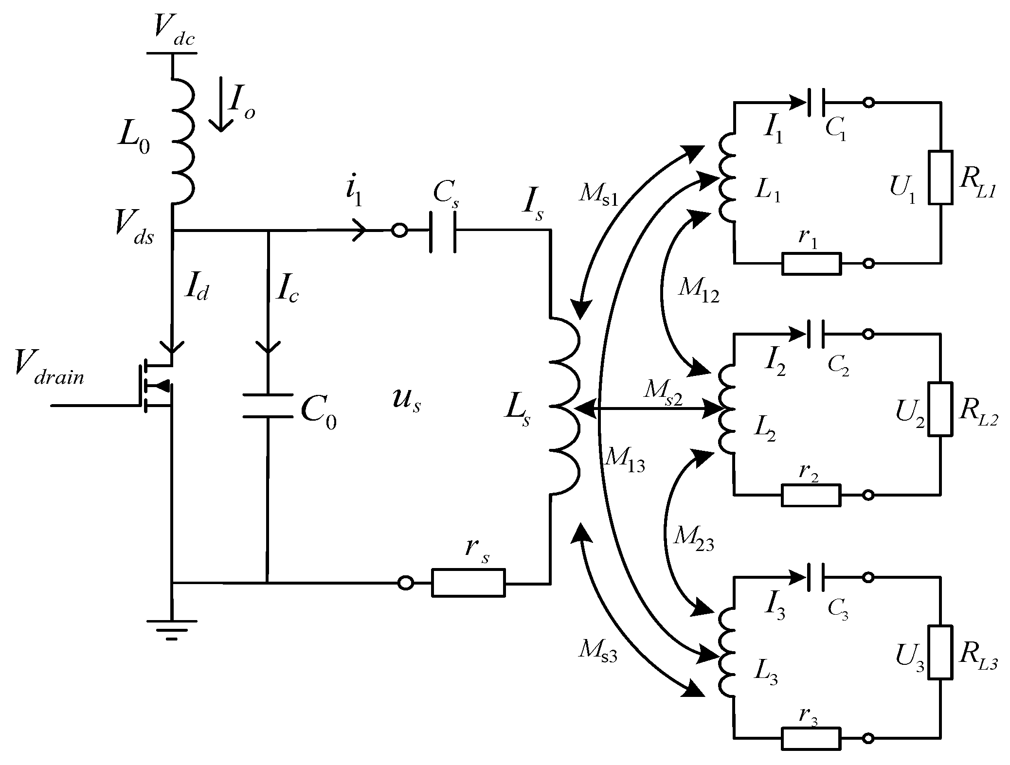
2.1. Circuit Models of Wireless Power Transfer System
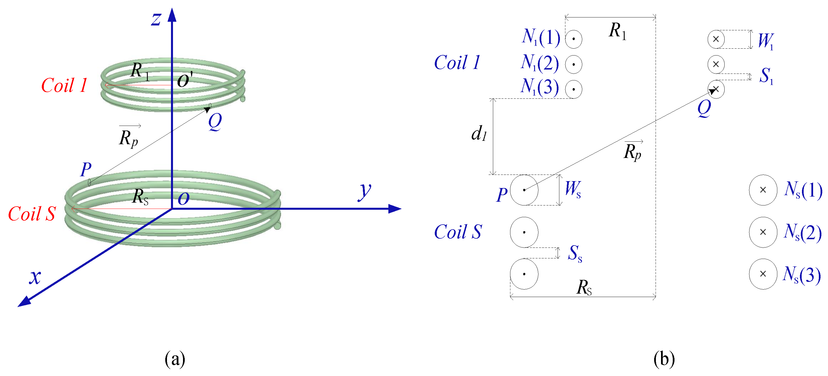
2.2. Mutaual Inductance of Coupled Coils
2.2.1. Mutual Inductance of Perfectly Aligned Coils
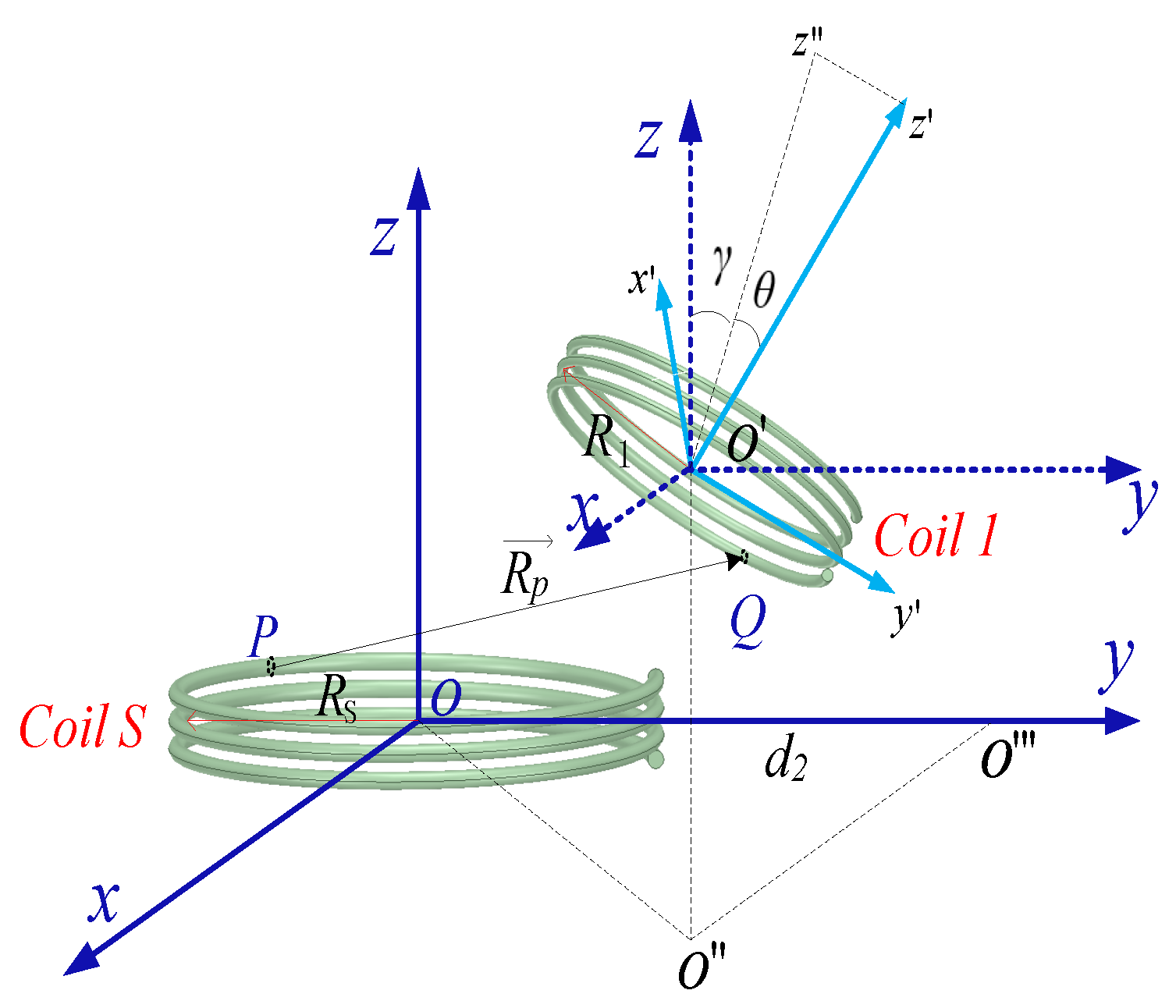
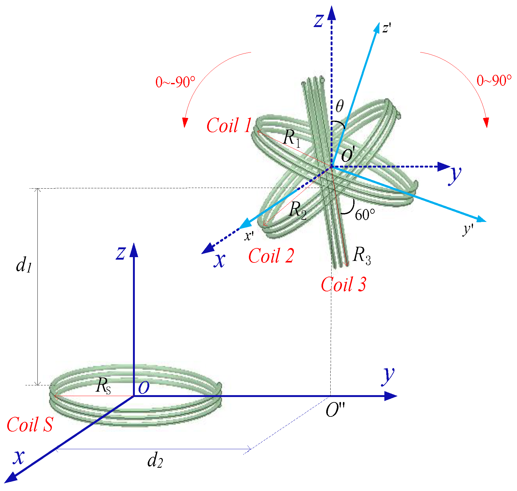
2.2.2. Mutual Inductance of Horizontal Offset and Angular Deflection Coils
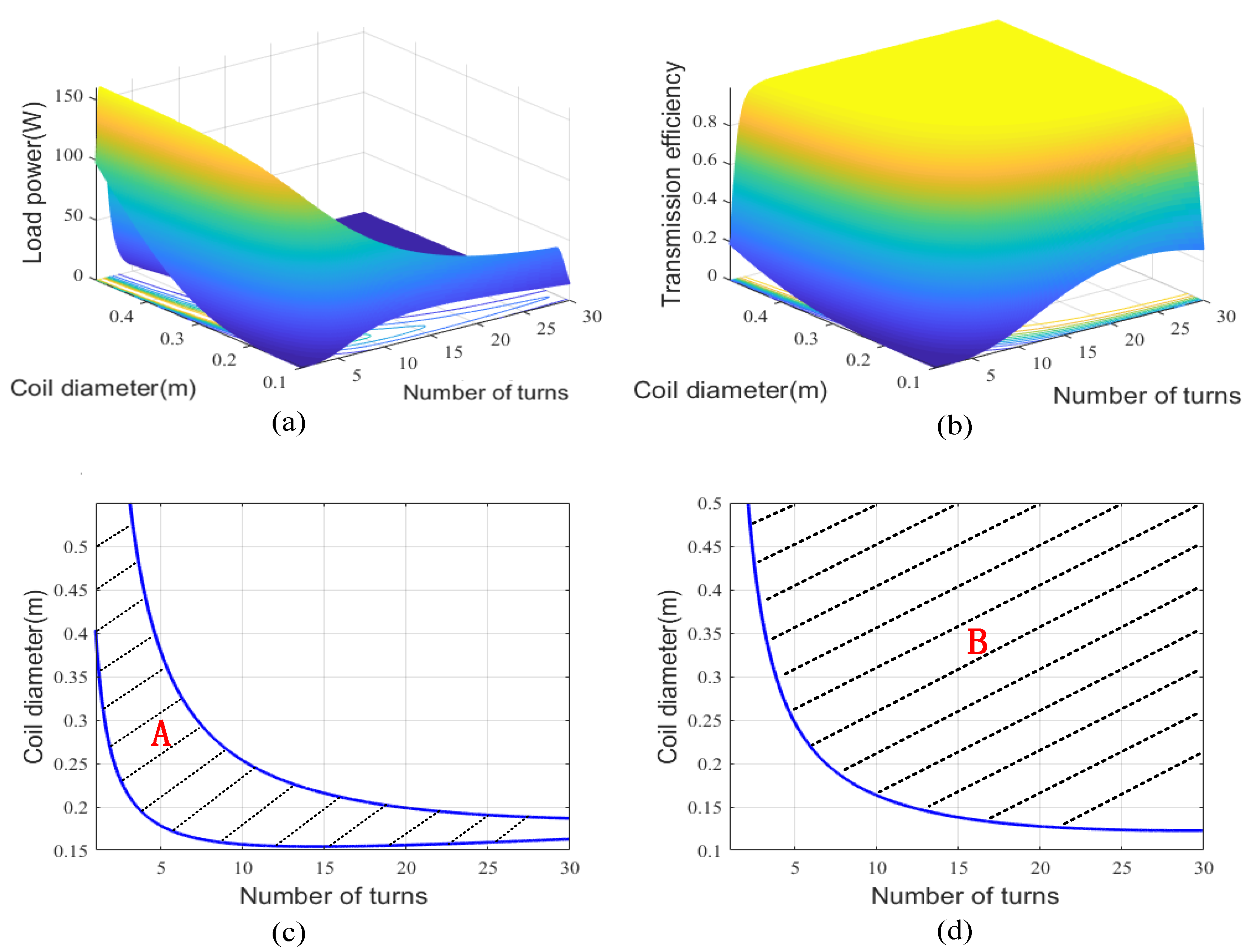
3. Duantificationally Design of Coil Parameters
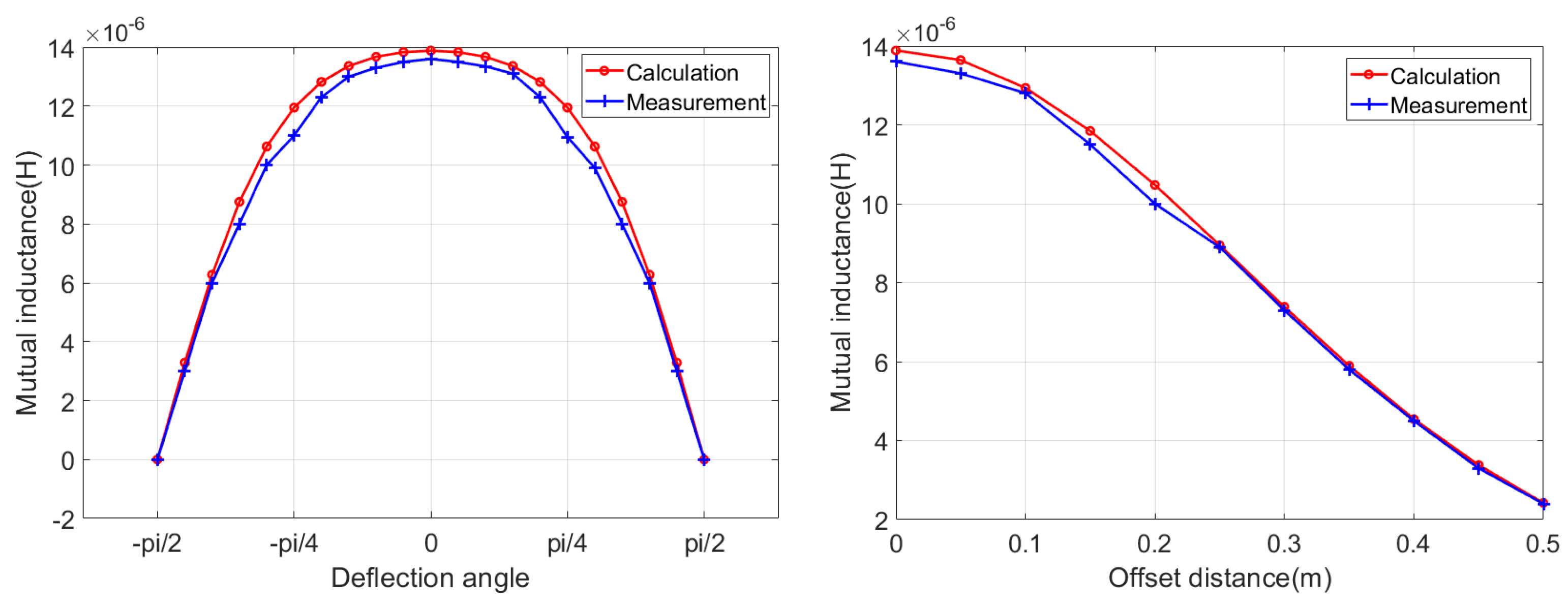
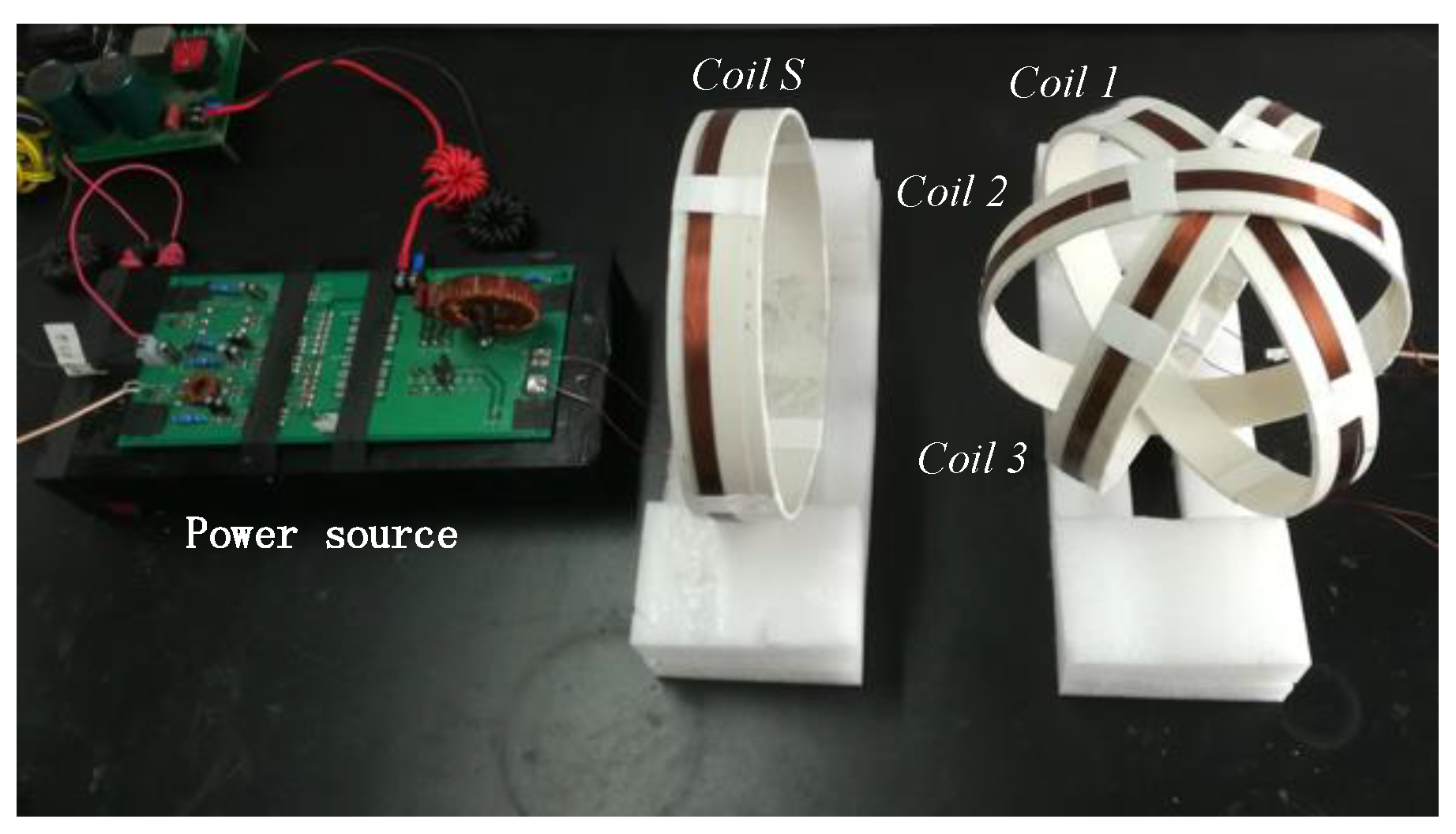
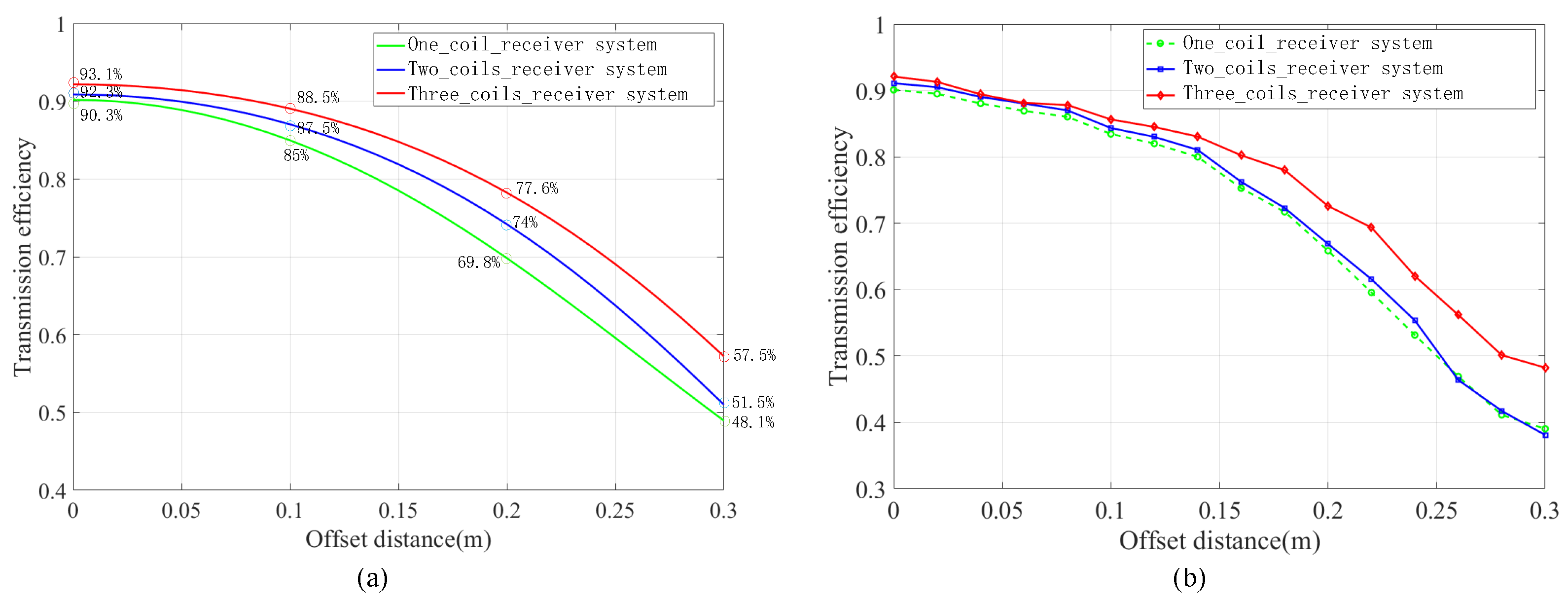
4. Simulation Analysis and Experimental Verification
5. Conclusions
Author Contributions
Funding
Institutional Review Board Statement
Informed Consent Statement
Data Availability Statement
Acknowledgments
Conflicts of Interest
References
- Nguyen, M.Q.; Hughes, Z.; Woods, P.; Seo, Y.S.; Rao, S.; Chiao, J.C. Field Distribution Models of Spiral Coil for Misalignment Analysis in Wireless Power Transfer Systems. IEEE Trans. Microw. Theory Tech. 2014, 62, 920–930. [Google Scholar] [CrossRef]
- Zhang, B.; Xu, W. Review of low-loss wireless power transfer methods for autonomous underwater vehicles. IET Power Electron. 2022, 15, 775–788. [Google Scholar] [CrossRef]
- Zhang, X.Y.; Xue, C.D.; Lin, J.K. Distance-Insensitive Wireless Power Transfer Using Mixed Electric and Magnetic Coupling for Frequency Splitting Suppression. IEEE Trans. Microw. Theory Tech. 2017, 65, 4307–4316. [Google Scholar] [CrossRef]
- Hu, H.; Georgakopoulos, S. Multiband and Broadband Wireless Power Transfer Systems Using the Conformal Strongly Coupled Magnetic Resonance Method. IEEE Trans. Ind. Electron. 2017, 64, 4307–4316. [Google Scholar] [CrossRef]
- Lei, Z.; Thrimawithana, D.J.; Madawala, U.K.; Hu, P.; Mi, C.C. A Misalignment Tolerant Series-hybrid Wireless EV Charging System with Integrated Magnetics. IEEE Trans. Power Electron. 2018, 34, 1276–1285. [Google Scholar]
- Ming, L.; Fu, M.; Yong, W.; Chengbin, M.A. Battery Cell Equalization via Megahertz Multiple-Receiver Wireless Power Transfer. IEEE Trans. Power Electron. 2017, 33, 4135–4144. [Google Scholar]
- Wang, S.; Hu, Z.; Rong, C.; Lu, C.; Chen, J.; Liu, M. Planar Multiple-Antiparallel Square Transmitter for Position-Insensitive Wireless Power Transfer. IEEE Antennas Wirel. Propag. Lett. 2018, 17, 188–192. [Google Scholar] [CrossRef]
- Cheng, H.; Kawajiri, T.; Ishikuro, H. A 13.56-MHz Wireless Power Transfer System With Enhanced Load-Transient Response and Efficiency by Fully Integrated Wireless Constant-Idle-Time Control for Biomedical Implants. IEEE J. Solid-State Circuits 2017, 53, 538–551. [Google Scholar]
- Kim, J.; Kim, D.H.; Park, Y.J. Free-Positioning Wireless Power Transfer to Multiple Devices Using a Planar Transmitting Coil and Switchable Impedance Matching Networks. IEEE Trans. Microw. Theory Tech. 2016, 64, 3714–3722. [Google Scholar] [CrossRef]
- Jayathurathnage, P.K.S.; Alphones, A.; Vilathgamuwa, D.M.; Ong, A. Optimum Transmitter Current Distribution for Dynamic Wireless Power Transfer With Segmented Array. IEEE Trans. Microw. Theory Tech. 2018, 66, 346–356. [Google Scholar] [CrossRef]
- Dan, J.; Yong, Y.; Liu, F.; Ruan, X.; Wang, C. Modeling and investigation of magnetically coupled resonant wireless power transfer system with varying spatial scales. IEEE Trans. Power Electron. 2017, 32, 3240–3250. [Google Scholar]
- Guo, Y.; Wang, L.; Zhang, Y.; Li, S.; Liao, C. Rectifier Load Analysis for Electric Vehicle Wireless Charging System. IEEE Trans. Ind. Electron. 2018, 65, 6970–6982. [Google Scholar] [CrossRef]
- Zhao, Z.Q.; Chen, Y.H.; Fu, M.J.; He, C.L.; He, J.J.; Pang, Y.; Li, G.Q.; Lin, J.Z. Analysis of Wireless Energy Transmission Characteristics via Magnetic Resonances Based on Mutual Inductance Model. Appl. Mech. Mater. 2014, 513–517, 3489–3495. [Google Scholar] [CrossRef]
- Xiu, Z.; Ho, S.L.; Fu, W.N. Analysis and Optimization of Magnetically Coupled Resonators for Wireless Power Transfer. IEEE Trans. Magn. 2012, 48, 4511–4514. [Google Scholar]
- Yilmaz, T.; Hasan, N.; Zane, R.; Pantic, Z. Multi-Objective Optimization of Circular Magnetic Couplers for Wireless Power Transfer Applications. IEEE Trans. Magn. 2017, 53, 1–12. [Google Scholar] [CrossRef]
- Zhang, Z.; Zhang, B.; Wang, J. Optimal Design of Quadrature-Shaped Pickup for Omnidirectional Wireless Power Transfer. IEEE Trans. Magn. 2018, 54, 1–5. [Google Scholar]
- Qi, Z.; Mei, S.; Yao, S.; Tang, W.; Hu, A.P. Field Orientation Based on Current Amplitude and Phase Angle Control for Wireless Power Transfer. IEEE Trans. Ind. Electron. 2018, 65, 4758–4770. [Google Scholar]
- SaadMutashar, A.; Hannan, M.A.; Samad, S.A.; Aini, H. Inductive coupling links for lowest misalignment effects in transcutaneous implanted devices. Biomed. Tech. Biomed. Eng. 2014, 59, 257–268. [Google Scholar]
- Cheapanich, S.; Chan, A.; Intani, P. Study of wireless power transfer using series-parallel topology. In Proceedings of the 2017 International Electrical Engineering Congress (iEECON), Pattaya, Thailand, 8–10 March 2017. [Google Scholar]
- Takeda, U. Dual Transmitter Free-Positioning Wireless Power Transfer System with Optimum Switching Phase Detection Technique. In Proceedings of the 2018 IEEE/MTT-S International Microwave Symposium-IMS, Philadelphia, PA, USA, 10–15 June 2018. [Google Scholar]
- Talaat, M.; Metwally, H.M.B.; Arafa, I. Experimental and Simulation Study of Wireless Power Transfer Using Resonators With Coupled Electric Fields. IEEE Trans. Plasma Sci. 2018, 46, 2480–2487. [Google Scholar] [CrossRef]
- An, H.; Liu, G.; Li, Y.; Zhang, C. The transmission characteristics study of multi attitude reception magnetic coupling resonance wireless energy transmission system. In Proceedings of the 2018 IEEE MTT-S International Wireless Symposium (IWS), Chengdu, China, 6–10 May 2018; pp. 4108–4117. [Google Scholar]
- Su, Y.P.; Liu, X.; Hui, S.Y.R.; Su, Y.P.; Liu, X. Mutual Inductance Calculation of Movable Planar Coils on Parallel Surfaces. IEEE Trans. Power Electron. 2009, 24, 1115–1123. [Google Scholar] [CrossRef]
- Kerber, A.F.; Saitta, F.; Bristow, P.; Vernet, J. Mutual Inductance Calculation Between Circular Filaments Arbitrarily Positioned in Space: Alternative to Grover’s Formula. IEEE Trans. Magn. 2010, 46, 3591–3600. [Google Scholar]
- Babic, S.; Akyel, C. New Formulas for Mutual Inductance and Axial Magnetic Force Between Magnetically Coupled Coils: Thick Circular Coil of the Rectangular Cross-Section-Thin Disk Coil (Pancake). IEEE Trans. Magn. 2013, 49, 860–868. [Google Scholar] [CrossRef]
- Wu, J.; Dai, X.; Sun, Y.; Li, Y. A Node Role Dynamic Change Method Among Repeater, Receiver, and Decoupling Using Topology Switching in Multinode WPT System. IEEE Trans. Power Electron. 2021, 36, 11174–11182. [Google Scholar] [CrossRef]
- Reza, K.S.; Kumar, P.S.; Desmulliez, M.P.Y. Accurate Modeling of Coil Inductance for Near-Field Wireless Power Transfer. IEEE Trans. Microw. Theory Tech. 2018, 66, 4158–4169. [Google Scholar]


| System | R | N | W | S | f | ||||
|---|---|---|---|---|---|---|---|---|---|
| three-coils-system | 10 | 11 | 2 mm | 0.2 mm | 15 cm | 0 | 403 | 0 to | 1 MHz |
| System | R | N | W | S | f | ||||
|---|---|---|---|---|---|---|---|---|---|
| two-coils-system | 10 | 11 | 2 mm | 0.2 mm | 15 cm | 0 | 403 | 0 to | 1 MHz |
| one-coil-system | 10 | 11 | 2 mm | 0.2 mm | 15 cm | 0 | 403 | 0 to 2 | 1 MHz |
| Ref. | Receiver | |||||
|---|---|---|---|---|---|---|
| This paper | three coils | 93.13% | 92.12% | 92.58% | 93% | 92.3% |
| This paper | two coils | 90.2% | 91.4% | 92.3% | 91.2% | 90.1% |
| This paper | one coils | 90.2% | 87.4% | 78.2% | 50.3% | 19.9% |
| [18] | three coils | 26.85% | 28.67% | 33.6% | 32.26% | 25.09% |
| [22] | two coils | 90.2% | 91.4% | 91.8% | 90.5% | 89.8% |
| [19] | one coil | 55% | 32% | 17% | 8% | 5% |
| [20] | one coil | 65% | 62% | 56% | 50% |
Publisher’s Note: MDPI stays neutral with regard to jurisdictional claims in published maps and institutional affiliations. |
© 2022 by the authors. Licensee MDPI, Basel, Switzerland. This article is an open access article distributed under the terms and conditions of the Creative Commons Attribution (CC BY) license (https://creativecommons.org/licenses/by/4.0/).
Share and Cite
An, H.; Yuan, J.; Li, J.; Cao, L. Design and Analysis of Omnidirectional Receiver with Multi-Coil for Wireless Power Transmission. Electronics 2022, 11, 3103. https://doi.org/10.3390/electronics11193103
An H, Yuan J, Li J, Cao L. Design and Analysis of Omnidirectional Receiver with Multi-Coil for Wireless Power Transmission. Electronics. 2022; 11(19):3103. https://doi.org/10.3390/electronics11193103
Chicago/Turabian StyleAn, Huilin, Jian Yuan, Jun Li, and Liqiang Cao. 2022. "Design and Analysis of Omnidirectional Receiver with Multi-Coil for Wireless Power Transmission" Electronics 11, no. 19: 3103. https://doi.org/10.3390/electronics11193103
APA StyleAn, H., Yuan, J., Li, J., & Cao, L. (2022). Design and Analysis of Omnidirectional Receiver with Multi-Coil for Wireless Power Transmission. Electronics, 11(19), 3103. https://doi.org/10.3390/electronics11193103