Article

Integrating Communication and Sensor Arrays to Model and Navigate Autonomous Unmanned Aerial Systems

1
Department of Mathematics, Embry-Riddle Aeronautical University, Daytona Beach, FL 32114, USA
2
Department of Computer Science, Florida Southern College, Lakeland, FL 33801, USA
3
Department of Mathematics, Florida Southern College, Lakeland, FL 33801, USA
4
Department of Engineering, The University of Tennessee at Martin, Martin, TN 38238, USA
5
Department of Electrical, Computer, Software and Systems Engineering, Embry-Riddle Aeronautical University, Daytona Beach, FL 32114, USA
6
Department of Electrical and Computer Engineering, Florida International University, Miami, FL 33174, USA
*
Author to whom correspondence should be addressed.
Electronics 2022, 11(19), 3023; https://doi.org/10.3390/electronics11193023
Submission received: 30 August 2022 / Revised: 17 September 2022 / Accepted: 19 September 2022 / Published: 23 September 2022

Abstract

:
The emerging concept of drone swarms creates new opportunities with major societal implications. However, future drone swarm applications and services pose new communications and sensing challenges, particularly for collaborative tasks. To address these challenges, in this paper, we integrate sensor arrays and communication to propose a mathematical model to route a collection of autonomous unmanned aerial systems (AUAS), a so-called drone swarm or AUAS swarm, without having a base station of communication but communicating with each other using multiple spatio-temporal data. The theories of structured matrices, concepts in multi-beam beamforming, and sensor arrays are utilized to propose a swarm routing algorithm. We address the routing algorithm’s computational and arithmetic complexities, precision, and reliability. We measure bit-error-rate (BER) based on the number of elements in sensor arrays and beamformed output of the members of the swarm to authenticate and secure the routing for the decentralized AUAS networking. The proposed model has the potential to enable future drone swarm applications and services. Finally, we discuss future work on obtaining a machine-learning-based low-cost drone swarm routing algorithm.

1. Introduction

The positive use of drones or unmanned aerial systems (UAS) has the potential to save lives, increase safety and efficiency, and enhance science and engineering research. Drone swarms could act independently or autonomously; for example, drone swarms could be utilized to map and predict dangerous areas and assist first responders during civil emergencies [1,2]. Drone swarms are scalable, adaptive, and resilient. However, future drone swarm applications and services pose new communications and sensing challenges; for example, many collaborative tasks require communications and networking to enable intra-agent collaboration in dynamic environments, which existing networking protocols are unable to achieve, as pointed out by Air Force Research Laboratory—Information Directorate (AFRL/RI) in its BAA entitled “Elastic Tactical Networking for Autonomous Swarms” [3].
Multiple, autonomous, unmanned aerial systems (AUAS) can exhibit swarm behavior in airborne robots. Although AUAS consists of thousands of drones flying in formation based on artificial intelligence (AI), sometimes, it exhibits chaotic patterns due to swarm dynamics. The centrally controlled collections of drones are popular and used for entertainment, e.g., in stadiums to emulate firework displays. However, AUAS swarm robotics have a fully distributed control architecture through independent and secure agents. The secure multi-agent approach to flight control and navigation allows the distribution of trust via consensus mechanisms and smart contracts—making them robust against cyberattacks and agent failures. Navigation and swarm control dictate multi-hop data networking between nodes of the AUAS swarm. The AUAS network requires network capacity for control functions between the agents and requires low latency for precision, navigation, and maneuvering—not to mention negotiating challenging flight paths in dense environments without collision. Thus, in this paper, we propose an integration of communication and sensor arrays to route a collection of AUAS while facilitating high-performance aerial multi-agent systems in the most challenging of air spaces.
The development of 5G cellular networking enables the improvement of the capacity of beamforming on AUAS networking [4,5,6,7,8,9,10,11,12,13]. Different from the majority of the literature on UAS based on a single flying antenna system (as a hub) [14,15,16,17,18,19], we propose an AUAS swarm routing algorithm that is compatible with wideband multi-beam beamforming and based on multiple steering angles and multiple variations to optimize the routing with a decentralized communication system to increase efficiency, accuracy, and reliability. We obtain an AUAS swarm routing algorithm in which drones can communicate with each other efficiently and understand routing through decentralized multiple antenna array systems. Frankly, the quicker and more synchronized the decisions of each drone, the easier the swarm will navigate efficiently. A model based on AUAS swarm routing becomes more reliable when the decision-making processes are transparent and explainable. In general, it is difficult to define an accurate and reliable mathematical model to optimize drone swarm routing, but it is easy to draw a definition to model swarm routing having each drone understand each other and making a decision to determine optimal routing.
Deep neural network-based (DNN) machine learning (ML) algorithms provide solutions for human dynamics, channel state information (CSI), optimum detection, and array beamforming [20,21,22,23,24]. However, these are trained on simplified scenarios that either assume a single-user scenario without interface [25,26], or require exact CSI available to the users for CSI reconstruction at the base stations [25,27,28], or need an end-to-end network training to design a frequency division duplex multiple input-output system [29] for swarm routing. The drone swarm can route using ML-based spatial and temporal data. However, given the conventional digital signal processing (DSP) algorithms, such as the Multiple Signal Classification (MUSIC) and the Estimation of Signal Parameters via Rotational Invariance Techniques (ESPRIT), as well as sparse estimation methods of array manifold matrix [30,31,32,33,34,35,36,37,38,39] to determine spatio-temporal data are mostly based on a priori information and may not be suitable in beamforming-based AUAS routing algorithms. Thus, techniques have to be explored (i) to understand and simplify the mathematical interpretation of models described by AI, (ii) to reduce the computational and time burden in computing spatio-temporal data, and (iii) to design accurate and low-cost ML algorithms. As of the preliminary work, we propose a mathematical model, algorithm, and error threshold of the proposed model to route a drone swarm utilizing spatio-temporal data and multi-beam beamforming communication having decentralized flying antenna array systems.
Although beamforming is implemented to improve UAS networking, the conventional routing algorithms for UAS networking are based on ad hoc on-demand distance vector (AODV) and optimized link state routing (OLSR). AODV is decentralized, reactive, and has less overhead for management, which is robust to the dynamic topology. Nevertheless, the main drawbacks of AODV are the consumption of path discovery and the local optimization for routing generation [40,41]. In contrast, OLSR is a centralized algorithm that could achieve global optimization of routing generation with the sacrifice of overhead [42]. Compatible with beamforming, a swarm-oriented routing algorithm, implemented with decentralization and efficiency, is an urgent need for AUAS networking. Thus, challenges still remain to efficiently navigate drone swarms without centralized communications, obtain efficient algorithms to capture real-time spatio-temporal data in a massive and complex multiple-input multiple-output (MIMO) model, and address limitations in beamformed antenna arrays for AUAS routing. Here, we propose a mathematical model and address complexity, precision, and reliability to route an AUAS swarm while communicating with each other (without having a base station communication) through multiple spatio-temporal data based on theories of multi-beam beamforming, sensor arrays, and structured matrices.
The organization along with the contribution of the paper is as follows.
  • In Section 2, we propose a mathematical model followed by an algorithm and flow chart to navigate a drone swarm using multi-beam beamforming decentralized antenna array systems.
  • In Section 3, we present
    -
    the array received beamformed signals of drones in the drone swarm at time stamps and compare these received signals with output signals corresponding to a ground-truth action function having the same time stamps.
    -
    the analytical arithmetic complexity and numerical computational complexity of the proposed routing algorithm.
    -
    BER results based on the proposed AUAS swarm routing algorithm.
  • In Section 4, we discuss an ML algorithm for the completion of spatial and temporal data to obtain the AUAS swarm routing algorithm followed by a low-cost algorithm.
  • In Section 5, we conclude the paper.

2. MIMO Beamforming-Based Mathematical Model and Routing Algorithm to Navigate a Collection of AUAS

In this section, we propose a novel mathematical model to route an AUAS swarm based on MIMO beamforming. After the model is proposed, an algorithm is stated to route an AUAS swarm consisting of a massive number of drones. Thus, we will be able to deploy over 100 drones without using base station communication. The proposed method is different from the conventional AODV and is suitable for the 5G NR, B5G, and 6G cellular networking on the AUAS networking on a large scale. The difference between the scenarios is that the existing AODV can be deployed in a group and the members of the group can not exceed 100 [43,44].
We assume a drone swarm consists of M number of drones, and each drone—say u—has a uniform array with N elements and d element spacing. We also assume that there are M uncorrelated signals impinging on the array from M drones (to establish communication among drones) with unique directions { θ i } i = 1 M , amplitudes { a i } i = 1 M , and temporal variables { ω i } i = 1 M s.t. 2 π f i ω i < 2 π f i , where f i is the unique temporal frequency in each drone. Thus, the assumptions are made so that each drone could communicate using a unique RF beacon modulated at a low-rate digital waveform that carries a unique binary identification code. If x ( u ) ( t ) = x ( 0 , t ) , x ( 1 , t ) , , x ( M 1 , t ) T —say x ( u ) denotes the source signal of drone u at time t, then the array received N-beamformed signal of drone u at time t, i.e., y ( u ) ( ω i , a i , θ i , t ) = k = 0 , i = 1 N 1 , M a i e j ( ω i t k ω i ψ i ) x ( u ) + ȷ ( u ) , where ψ i = 2 π d λ sin ( θ i ) , λ denotes the wavelength of the incident signal, and ȷ ( u ) ( t ) = n 0 ( t ) , n 1 ( t ) , , n N 1 ( t ) T —say ȷ ( u ) as the additive white Gaussian noise (AWGN), takes the vector form y ( u ) ( ω i , a i , θ i , t ) = y ( 0 , t ) , y ( 1 , t ) , , y ( N 1 , t ) T —referred to as y ( u ) . Now, for all u’s we can rewrite y ( u ) ’s as a collection of matrix–vector products describing a MIMO beamforming model, and for each drone, u, described via:
y ( u ) = V k i ( u ) · S i ( u ) · x ( u ) + ȷ ( u ) ,
where V k i ( u ) = e j k ω i ψ i k = 0 , i = 1 N 1 , M is an N × M matrix determined by spatial and temporal frequencies of each drone u, which we call a frequency Vandermonde matrix, j 2 = 1 , and S i ( u ) = [ a i e j ω i t ] i = 1 M is an M × M matrix consisting of temporal frequencies and amplitudes (Recall that V k i ( u ) · S i ( u ) is called the array manifold matrix). Thus, we will have a set of M systems of equations, and for each drone u we have a system of N equations as given in (1).
The simplest example case of the Equation (1) can be described as having three drones with each consisting of four elements in the antenna array. Thus, we could see the overall system as a collection of three systems with each consisting of four sets of equations. Thus, if each drone received signals from other drones (while communicating with itself and the other two), the collection of 12-beamformed signals (4-beamformed signals per drone) can be put into a collection of matrix–vector form as follows
y 4 × 1 ( 1 ) y 4 × 1 ( 2 ) y 4 × 1 ( 3 ) = V k i ( 1 ) · S i ( 1 ) k = 0 , i = 1 3 , 3 0 0 0 V k i ( 2 ) · S i ( 2 ) k = 0 , i = 1 3 , 3 0 0 0 V k i ( 3 ) · S i ( 3 ) k = 0 , i = 1 3 , 3 12 × 9 x 3 × 1 ( 1 ) x 3 × 1 ( 2 ) x 3 × 1 ( 3 ) + ȷ 4 × 1 ( 1 ) ȷ 4 × 1 ( 2 ) ȷ 4 × 1 ( 3 ) ,
where 0 denotes zero matrices.
Following the proposed model (1), we state a simple algorithm (Algorithm 1) to present N-beamformed received signals for each drone u at time t, i.e., y ( u ) ( ω i , a i , θ i , t ) , where x ( u ) ( t ) denotes the source signal of drone u at time t.
Algorithm 1 Multi-beam beamforming-based AUAS swarm routing algorithm
Input: M, N, f i , and t.
Output:  y ( 1 ) , y ( 2 ) , , y ( M ) .

1.  for  i = 1 to M
     compute θ i , a i , ω i , and ψ i

2.  for  u = 1 to M
     compute x ( u ) at t

3.  for  u = 1 to M
    for  k = 1 to N
     for  i = 1 to M
      construct S i ( u ) and V k i ( u )
     end for i
    end for k
     z ( u ) S i ( u ) · x ( u ) y ( u ) V k i ( u ) · z ( u )
   end for u

4.   return  y ( 1 ) , y ( 2 ) , , y ( M )
For further clarification, we present a flowchart corresponding to the AUAS swarm model followed by the algorithm as shown in Figure 1.

3. Results

In this section, we first present the received N-beamformed array of signals in each drone at different time stamps to assess the performance of the proposed mathematical model. Next, we show numerical results based on the computational complexity of the proposed AUAS swarm routing algorithm and show that it is compatible with the analytical arithmetic complexity. Finally, we show the BER results of the proposed routing algorithm to understand the communication among drones in the swarm.

3.1. Beamfomed Output of the AUAS Swarm Routing Model

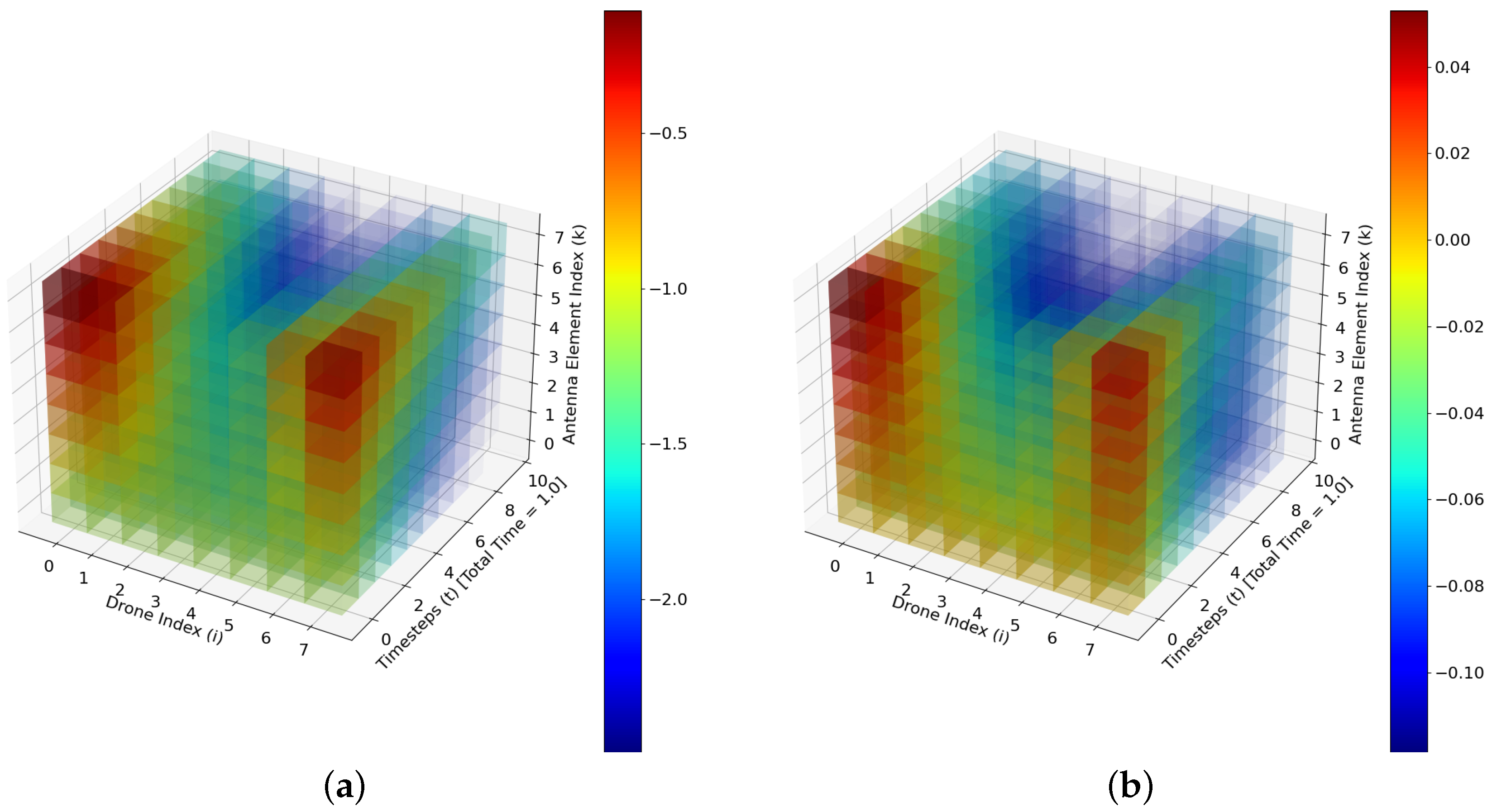
In order to understand the error threshold of the proposed AUAS swarm routing model, we compare the N-beamformed signals in antenna arrays of each drone at time t with a ground-truth activation function γ u , i , k t = i = 1 M sin 2 π β u , i , k + t , where β u , i , k is the distance from drone u’s k t h antenna element to each antenna element of drone i at time t. As we have taken the activation function in terms of sine, and beamformed outputs are complex-valued vectors, for the generation of Figure 2, we compare the activation function with the magnitude of the beamformed output vector times the sine value of the phase of the beamformed output of all drones in spatial arrangements of drones at a given time experienced by each element of the antenna array, i.e., i = 1 M | y ( u ) | · sin arctan I m a g ( V k i ( u ) · S i ( u ) · x ( u ) ) , R e a l ( V k i ( u ) · S i ( u ) · x ( u ) ) . For the generation of Figure 2, we have assumed that each drone is spatially arranged equidistantly along the circumference of a circle whose radius is one spatial unit such that the angle α from the center of the circular formation to drone u is α i ( u ) = 2 π M i , where the center of the formation is the origin so that each drone u’s spatial coordinates are x ( u ) , y ( u ) = cos α ( u ) , sin α ( u ) . Moreover, we assume that the amplitude of the received signal of drone i from drone u is a i ( u ) = 1 and each drone’s linear N-element antenna array is oriented horizontally, such that an antenna k’s spatial coordinates of drone u are x ( u ) + d k 1 , y ( u ) , where d = 0.01 is the inter-element distance of the antenna arrays. Thus, Figure 2 depicts the N-beamformed signals (color codes to show the strength of the signals) in antenna arrays of M number of drones (without having base station communication) at time steps t = 0 , 0.1 , 0.2 , . . . 0.9 , i.e., y ( u ) ( ω i , a i , θ i , t ) when u and i runs from 1 , 2 , , M and M = N = 8 .
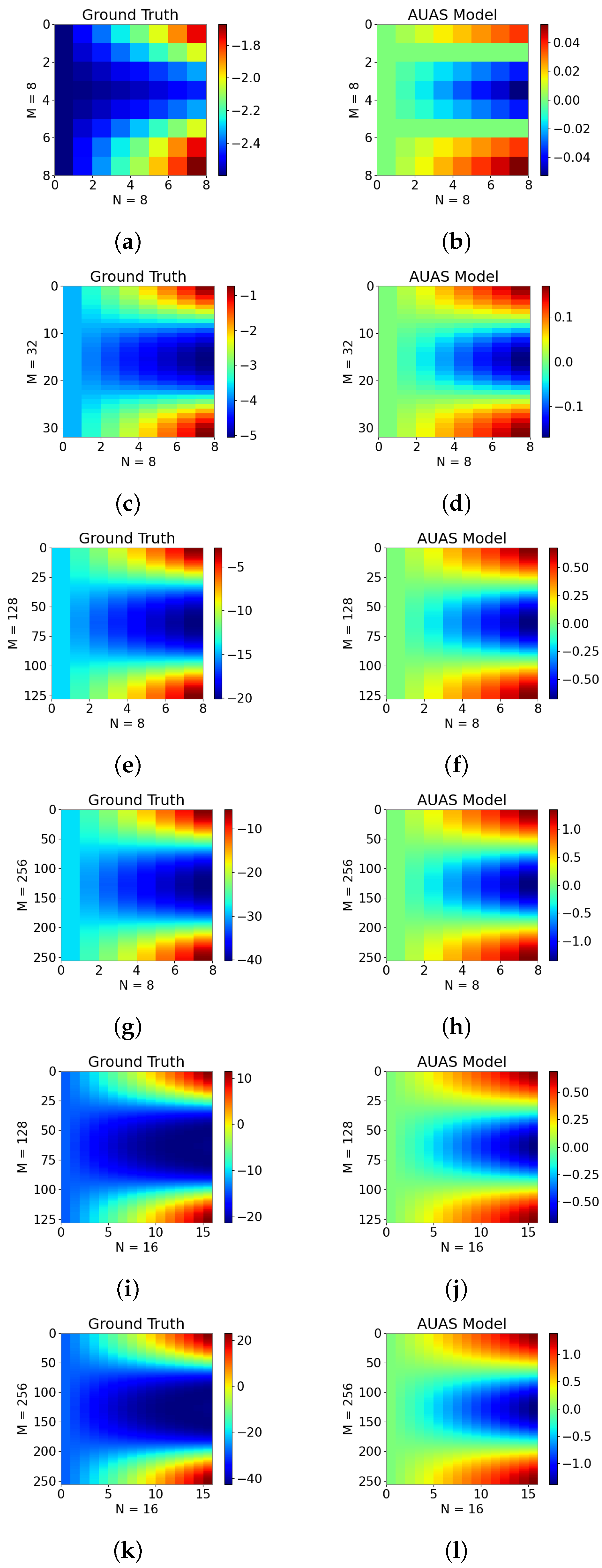
Next in Figure 3; (a)–(l), we show the 2D projections of 3D views of the N-beamformed signals in antenna arrays of M number of drones at time t and the ground-truth signals of the activation function at a time t extending the illustration in Figure 2 with different M and N values. As shown in Figure 3; (a)–(h), the beamformed output of the proposed AUAS swarm algorithm shows similar results as the ground-truth signals of the activation function except for a few beamformed signals, and the effect becomes minor when the number of drones increases. When we fix the number of drones and increase the number of elements in the antenna arrays at t = 0 , say M = 128 or 256 as in Figure 3; (g)–(l), the beamformed output of the proposed AUAS swarm algorithm does not show favorable results with the ground-truth signals of the activation function as in the N = 8 case, but not significantly. Thus, we will explore the deviations of the beamformed output of the proposed model and activation function as in Section 4.

3.2. Complexity of the AUAS Swarm Routing Algorithm

In this section, we will discuss the arithmetic and computational complexity of the proposed AUAS swarm routing algorithm. Let us start with the arithmetic complexity of the proposed algorithm.
Proposition 1.
The arithmetic complexity of the algorithm corresponding to the AUAS swarm model (1) having M number of drones, and each drone consisting of a uniform linear array with N-elements is O ( N M 2 ) .
Proof. 
We have M-sets of N-beamformed signals of M-drones, i.e., [ y ( 1 ) , y ( 2 ) , , y ( M ) ] as the columns of a throughput matrix to navigate the AUAS swarm. As each N-beamformed signal y ( u ) correspondences to each drone described via (1), the computation of the throughput matrix cost O ( N M 2 ) . □
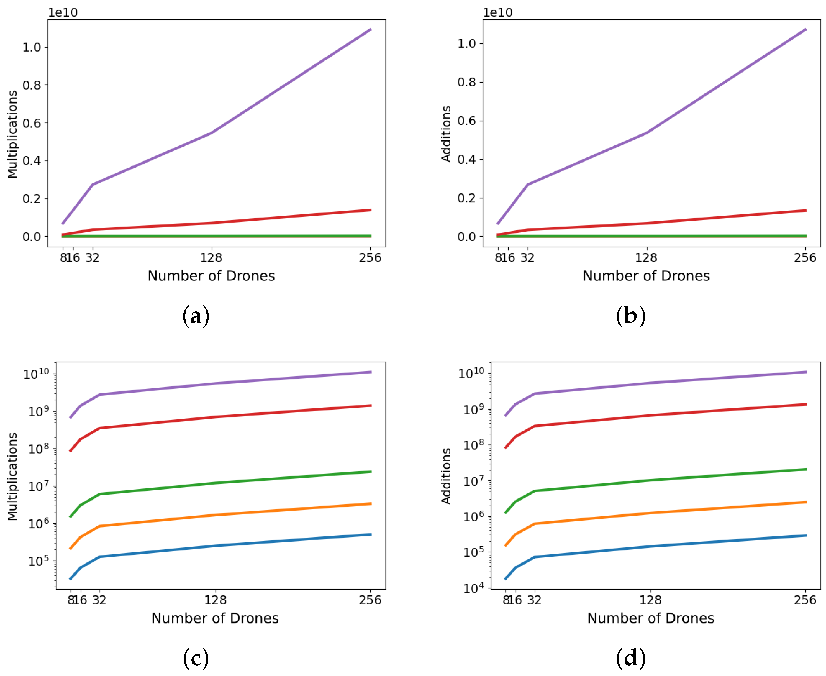
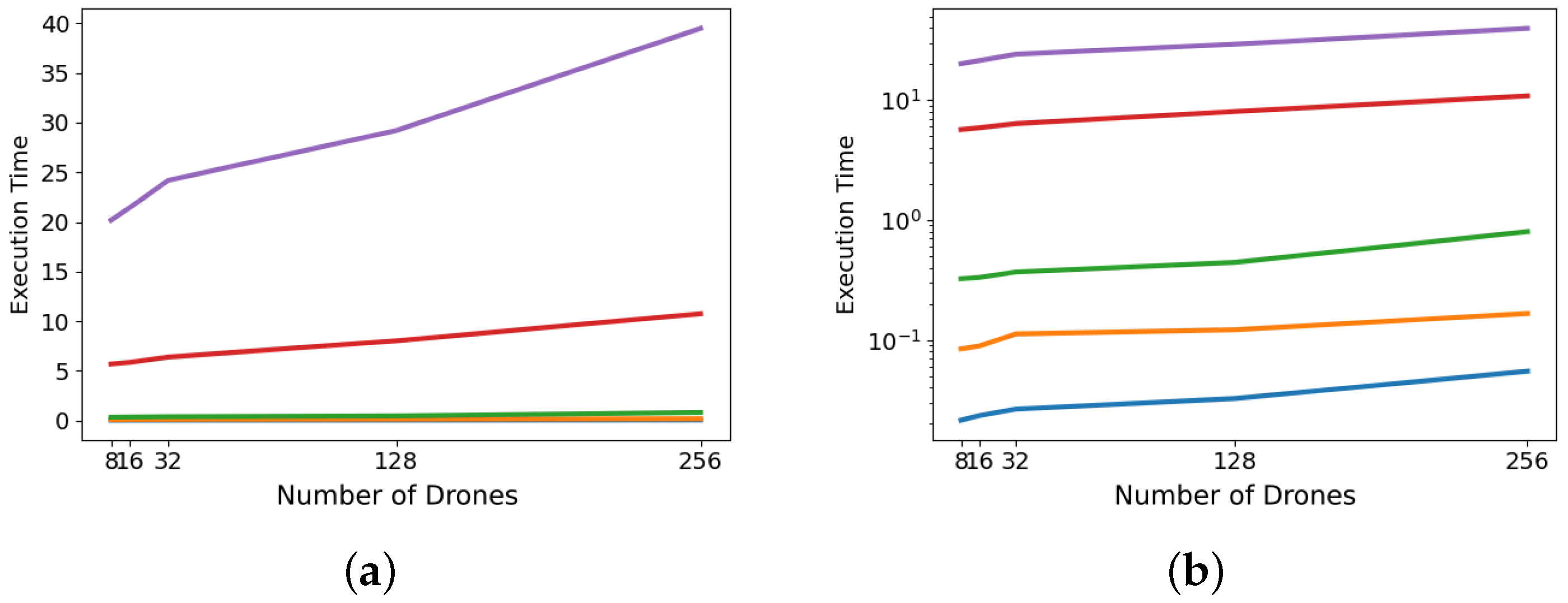
Figure 4 and Figure 5 show the proportionality between the arithmetic and computational complexities of the proposed AUAS swarm routing algorithm. Figure 4 depicts the execution time, algorithmic additions, and algorithmic multiplications of the proposed algorithm based on the code written in Python. The x-axis and y-axis show the number of drones and the complexity of the graph, respectively. Each line in the graphs shows the number of elements in the antenna arrays which are 64, 32, 16, 8, and 4 from top to bottom. Thus, it is evident that the execution time is directly proportional to the arithmetic complexity as in Proposition 1. For a better visual purpose in showing the algorithmic complexity variation based on the elements of the antenna array, we present Figure 5 on a logarithmic scale. Based on this figure, the computational complexity, algorithmic additions, and algorithmic multiplications increase as the number of drones and/or elements of the antenna arrays increases, and hence the computational complexity is proportional to the arithmetic complexity in Proposition 1.
Remark 1.
Although particle swarm optimization is a popular stochastic optimization method, it may not always provide low-complexity routing algorithms [45,46]. Authors in [47] compared the performance of the particle swarm optimization and differential evolution techniques to find delivery routings with minimum travel distances with quadratic complexity in time and space. This complexity is calculated based on a spatial distance matrix from the deployment to the landing. Thus, once the AUAS swarm is deployed based on the proposed model, the proposed algorithm also has quadratic complexity in time as in Proposition 1 because N remains a constant after deployment.

3.3. Bit-Error-Rate Based on the AUAS Swarm Routing Model

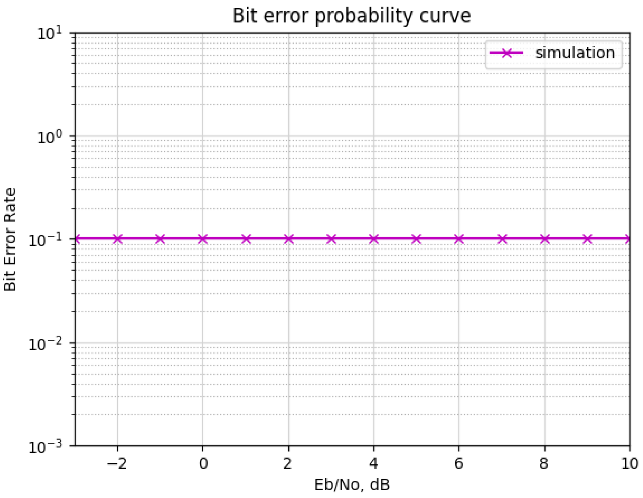
We use the BER to understand the mutual communication among drones as it gives a measurement of bits that have errors relative to the total number of bits received in a transmission (usually denoted by ten to a negative power). Following [48], we have shown the BER of the proposed AUAS swarm routing algorithm over a collection of signal-to-noise ratios (SNR). As shown in Figure 6, when SNR increases, the BER displays constant behavior, and hence implies that there is a communication loss or delay among drones. The simulated BER is calculated using the beamformed output signals y ( u ) and source signals x ( u ) multiplied by an offset factor 1.022 for 20 drones, each having an antenna array with 32 elements. If the magnitude of the beamformed output vector y ( u ) is greater than the magnitude of the source signal vector x ( u ) , then we set the bit value to zero and otherwise the bit value to one (this is undertaken to convert the vector quantities into bits). Next, the AWGN is added to y ( u ) in order to introduce noise to the beamformed output signal. The AWGN is calculated as 1 2 n , where n is a randomly generated complex number. Following this, the positive real part of the beamformed output signal y ( u ) is compared with the bit value conversions. The BER is encountered when these quantities are different. These bit-errors are summed and divided by the number of bits in the transmit signal and show the resulted BER over SNR as in Figure 6.

4. Discussion

In this section, we discuss the variation of the graphs for the beamformed output of the proposed AUAS swarm model with the ground-truth activation function as shown in Section 3. We sum up the discussion to obtain a low-cost AUAS swarm routing algorithm exploring the structures of the matrices and ML algorithms. For the purposes of understanding the variation of beamformed output of the proposed AUAS swarm model with the ground-truth activation function in Figure 3, we utilize min–max normalization following the formula y = y y m i n y m a x y m i n , where y is a scalar value in y ( u ) or γ u , i , k t , y m i n is the minimum scalar element of the tensor that contains each drone u’s beamformed signal y ( u ) for each time t or ground-truth signal γ u , i , k t for each time, y m a x is the maximum scalar value from this tensor, and y is the input value normalized to fall between the range 0 , 1 [49].
Figure 7 shows the consistency between the beamformed output of the proposed model and the ground activation function. The magnitude of error depicted for higher values of k (i.e., number of elements in the antenna array) will not occur in practice because d k represents the positive horizontal offset of any antenna array element k from the center of the drone’s spatial coordinate. We measure the difference between the imaginary part of the beamformed output and the activation function and the magnitude of it as shown in Figure 7c,d, respectively. The robust accuracy of the proposed algorithm shows small k values, which we mostly see in practice. Thus, the proposed AUAS swarm routing algorithm is useful as a heuristic, e.g., as a metric to sort a collection of neighboring drones according to their connection strength with any particular drone. The difference between a collection of ground-truth signals and the output beamformed signals of the AUAS swarm model would increase as the number of elements in the antenna arrays, i.e., N increases and/or the offset size d k increases but remains consistent even for large spatial drone arrangements. Thus, we will seek artificial-neural-network-based ML algorithms for the completion of the frequency Vandermonde matrices defined via spatial and temporal data to obtain a closed-form algorithm (while reducing the error as best as possible) and hence to navigate a massive collection of AUAS in real-time, in future.
Extending the future work, we have observed that in the AUAS swarm model (1), the most expensive calculation occurs in the brute-force computation of the matrix–vector products. Although S i ( u ) is a diagonal matrix, V k i ( u ) is a dense matrix. Fortunately, V k i ( u ) is a Vandermonde structured matrix having nodes { e j ω i ψ i } i = 1 M . Thus, in future, we will use the M-set of N-beamformed signal of M drones at time t, i.e., y ( 1 ) y ( 2 ) y ( M ) as the columns of a throughput matrix and optimize the routing of AUAS swarm using low-complexity multi-beam beamforming algorithms described in [50,51,52]. For fast missing data inference, we will propose to explore the inherent data relation between vectors in consecutive time frames to quickly fill in the missing data in the new time slot using a vector autoregression method followed by a product of highly sparse and low-rank matrices to estimate the transition matrices V ^ k i ( u ) characterizing the interaction among different components.

5. Conclusions

We have integrated communication and sensor arrays to propose a mathematical model to route a collection of AUAS, without having a base station of communication but by communicating with each other using multiple spatio-temporal data. The theories of structured matrices, concepts in multi-beam beamforming, and sensor arrays were utilized to propose a swarm routing algorithm. We have addressed the routing algorithm’s computational and arithmetic complexities, precision, and reliability. We have measured BER based on the number of elements in sensor arrays and beamformed output of the members of the swarm to authenticate and secure the routing for the decentralized AUAS networking. Finally, we have discussed future work on obtaining an ML-based low-cost AUAS swarm routing algorithm.

Author Contributions

Conceptualization, S.M.P.; theory, S.M.P.; software, R.J.M.; validation, S.M.P., R.J.M., K.S. and K.B.; formal analysis, S.M.P. and R.J.M.; investigation, S.M.P. and A.M.; resources, S.M.P. and H.S.; data curation, S.M.P. and R.J.M.; writing—original draft preparation, S.M.P., R.J.M., K.S., K.B. and H.S.; writing—review and editing, S.M.P. and H.S.; visualization, R.J.M., K.S. and K.B.; supervision, S.M.P.; project administration, S.M.P. and H.S.; funding acquisition, H.S. and S.M.P. All authors have read and agreed to the published version of the manuscript.

Funding

This research was partially supported by the National Science Foundation under Grant No. 2150213.

Institutional Review Board Statement

Not applicable.

Informed Consent Statement

Not applicable.

Data Availability Statement

In the future, we will provide data in the public domain using a GitHub account.

Acknowledgments

The authors would like to thank Jian Wang for the discussions on BER analysis.

Conflicts of Interest

The authors declare no conflict of interest.

Abbreviations

The following abbreviations are used in this manuscript:
AUASAutonomous Unmanned Aerial Systems
BERBit-error-rate
DNNDeep neural network
MLMachine learning
CSIChannel state information
DSPDigital signal processing
MUSICMultiple Signal Classification
ESPRITEstimation of Signal Parameters via Rotational Invariance Technique
AIArtificial Intelligence
MIMOMultiple-input multiple-output
AODVad-hoc on-demand distance vector

References

  1. Chung, S.J.; Paranjape, A.A.; Dames, P.; Shen, S.; Kumar, V. A Survey on Aerial Swarm Robotics. IEEE Trans. Robot. 2018, 34, 837–855. [Google Scholar] [CrossRef]
  2. Tahir, A.; Böling, J.; Haghbayan, M.H.; Toivonen, H.T.; Plosila, J. Swarms of Unmanned Aerial Vehicles—A Survey. J. Ind. Inf. Integr. 2019, 16, 100106. [Google Scholar] [CrossRef]
  3. Elastic Tactical Networking for Autonomous Swarms. 2017. Available online: https://govtribe.com/opportunity/federal-contract-opportunity/elastic-tactical-networking-for-autonomous-swarms-fa875018s7004 (accessed on 4 January 2021).
  4. Huang, Y.; Wu, Q.; Wang, T.; Zhou, G.; Zhang, R. 3D Beam Tracking for Cellular-Connected UAV. IEEE Wirel. Commun. Lett. 2020, 9, 736–740. [Google Scholar] [CrossRef]
  5. Agiwal, M.; Roy, A.; Saxena, N. Next Generation 5G Wireless Networks: A Comprehensive Survey. IEEE Commun. Surv. Tutorials 2016, 18, 1617–1655. [Google Scholar] [CrossRef]
  6. Lin, Z.; Lin, M.; de Cola, T.; Wang, J.B.; Zhu, W.P.; Cheng, J. Supporting IoT With Rate-Splitting Multiple Access in Satellite and Aerial-Integrated Networks. IEEE Internet Things J. 2021, 8, 11123–11134. [Google Scholar] [CrossRef]
  7. Lin, Z.; Niu, H.; An, K.; Wang, Y.; Zheng, G.; Chatzinotas, S.; Hu, Y. Refracting RIS-Aided Hybrid Satellite-Terrestrial Relay Networks: Joint Beamforming Design and Optimization. IEEE Trans. Aerosp. Electron. Syst. 2022, 58, 3717–3724. [Google Scholar] [CrossRef]
  8. Huang, Q.; Lin, M.; Wang, J.B.; Tsiftsis, T.A.; Wang, J. Energy Efficient Beamforming Schemes for Satellite-Aerial-Terrestrial Networks. IEEE Trans. Commun. 2020, 68, 3863–3875. [Google Scholar] [CrossRef]
  9. Lin, Z.; Lin, M.; Zhu, W.P.; Wang, J.B.; Cheng, J. Robust Secure Beamforming for Wireless Powered Cognitive Satellite-Terrestrial Networks. IEEE Trans. Cogn. Commun. Netw. 2021, 7, 567–580. [Google Scholar] [CrossRef]
  10. An, K.; Liang, T. Hybrid Satellite-Terrestrial Relay Networks With Adaptive Transmission. IEEE Trans. Veh. Technol. 2019, 68, 12448–12452. [Google Scholar] [CrossRef]
  11. Jia, M.; Zhang, X.; Gu, X.; Guo, Q.; Li, Y.; Lin, P. Interbeam Interference Constrained Resource Allocation for Shared Spectrum Multibeam Satellite Communication Systems. IEEE Internet Things J. 2019, 6, 6052–6059. [Google Scholar] [CrossRef]
  12. Li, B.; Fei, Z.; Chu, Z.; Zhou, F.; Wong, K.K.; Xiao, P. Robust Chance-Constrained Secure Transmission for Cognitive Satellite–Terrestrial Networks. IEEE Trans. Veh. Technol. 2018, 67, 4208–4219. [Google Scholar] [CrossRef]
  13. Du, J.; Jiang, C.; Zhang, H.; Wang, X.; Ren, Y.; Debbah, M. Secure Satellite-Terrestrial Transmission Over Incumbent Terrestrial Networks via Cooperative Beamforming. IEEE J. Sel. Areas Commun. 2018, 36, 1367–1382. [Google Scholar] [CrossRef]
  14. Messous, M.A.; Arfaoui, A.; Alioua, A.; Senouci, S.M. A Sequential Game Approach for Computation-Offloading in an UAV Network. In Proceedings of the GLOBECOM 2017—2017 IEEE Global Communications Conference, Singapore, 4–8 December 2017; pp. 1–7. [Google Scholar] [CrossRef]
  15. Li, B.; Fei, Z.; Zhang, Y.; Guizani, M. Secure UAV Communication Networks over 5G. IEEE Wirel. Commun. 2019, 26, 114–120. [Google Scholar] [CrossRef]
  16. Zhou, F.; Hu, R.Q.; Li, Z.; Wang, Y. Mobile Edge Computing in Unmanned Aerial Vehicle Networks. IEEE Wirel. Commun. 2020, 27, 140–146. [Google Scholar] [CrossRef]
  17. Li, B.; Fei, Z.; Zhang, Y. UAV Communications for 5G and Beyond: Recent Advances and Future Trends. IEEE Internet Things J. 2019, 6, 2241–2263. [Google Scholar] [CrossRef]
  18. Secinti, G.; Darian, P.B.; Canberk, B.; Chowdhury, K.R. SDNs in the Sky: Robust End-to-End Connectivity for Aerial Vehicular Networks. IEEE Commun. Mag. 2018, 56, 16–21. [Google Scholar] [CrossRef]
  19. Sun, X.; Yang, W.; Cai, Y. Secure Communication in NOMA-Assisted Millimeter-Wave SWIPT UAV Networks. IEEE Internet Things J. 2020, 7, 1884–1897. [Google Scholar] [CrossRef]
  20. Restuccia, F.; Medlodia, T. Deep Learning at the Physical Layer: System Challenges and Applications to 5G and Beyond. IEEE Commun. Mag. 2020, 58, 58–64. [Google Scholar] [CrossRef]
  21. He, R.; Dingm, Z. (Eds.) Applications of Machine Learning in Wireless Communications; ProQuest Ebook Central, 2019. Available online: https://app.knovel.com/kn/resources/kpAMLWC004/toc (accessed on 20 August 2022).
  22. Eugenio, M.; Cayamcela, M.; Lee, H.; Lim, W. Machine Learning for 5G/B5G Mobile and Wireless Communications: Potential, Limitations, and Future Directions. IEEE Access 2019, 7, 137184–137206. [Google Scholar]
  23. Jagannath, J.; Polosky, N.; Jagannath, A.; Restuccia, F.; Melodia, T. Machine Learning Paradigms for Next-Generation Wireless Networks. IEEE Wirel. Commun. 2017, 24, 98–105. [Google Scholar]
  24. Jagannath, J.; Polosky, N.; Jagannath, A.; Restuccia, F.; Melodia, T. Machine learning for wireless communications in the Internet of Things: A comprehensive survey. Ad Hoc Netw. 2019, 93, 101913. [Google Scholar] [CrossRef] [Green Version]
  25. Wen, C.; Shih, W.; Jin, S. Deep learning for massive MIMO CSI feedback. IEEE Wireless Commun. Lett. 2018, 7, 748–751. [Google Scholar] [CrossRef]
  26. Jang, J.; Lee, H.; Hwang, S.; Ren, H.; Lee, I. Deep learning-based limited feedback designs for MIMO systems. IEEE Wireless Commun. Lett. 2020, 9, 558–561. [Google Scholar] [CrossRef]
  27. Lu, C.; Xu, W.; Shen, H.; Zhu, J.; Wang, K. MIMO channel information feedback using deep recurrent network. IEEE Commun. Lett. 2019, 23, 188–191. [Google Scholar] [CrossRef]
  28. Guo, J.; Yang, X.; Wen, C.; Jin, S.; Li, G. DL-based CSI feedback and cooperative recovery in massive MIMO. arXiv 2020, arXiv:2003.03303. [Google Scholar]
  29. Sohrabi, F.; Attiah, K.M.; Yu, W. Deep Learning for Distributed Channel Feedback and Multiuser Precoding in FDD Massive MIMO. arXiv 2020, arXiv:2007.06512v1. [Google Scholar] [CrossRef]
  30. Schmidt, R. Multiple emitter location and signal parameter estimation. IEEE Trans. Antennas Propag. 1986, 34, 276–280. [Google Scholar] [CrossRef]
  31. He, Z.; Liu, Q.; Jin, L.; Ouyang, S. Low complexity method for DOA estimation using array covariance matrix sparse representation. Electron. Lett. 2013, 49, 228–230. [Google Scholar] [CrossRef]
  32. Richard Roy, T.K. ESPRIT-estimation of signal parameters via rotational invariance techniques. IEEE Trans. Acoust. Speech, Signal Process. 1989, 37, 984–995. [Google Scholar]
  33. Yin, J.; Chen, T.Q. Direction-of-arrival estimation using a sparse representation of array covariance vectors. IEEE Trans. Signal Process. 2011, 59, 4489–4493. [Google Scholar] [CrossRef]
  34. Lin, B.; Liu, J.; Xie, M.; Zhu, J. Sparse Signal Recovery for Direction-of-Arrival Estimation Based on Source Signal Subspace. J. Appl. Math. 2014, 2014, 101–111. [Google Scholar] [CrossRef]
  35. He, Z.; Shi, Z.; Huang, L.; So, H. Underdetermined DOA estimation for wideband signals using robust sparse covariance fitting. IEEE Signal Process. Lett. 2015, 22, 435–439. [Google Scholar] [CrossRef]
  36. Si, W.; Qu, X.; Qu, Z. Off-Grid DOA Estimation Using Alternating Block Coordinate Descent in Compressed Sensing. Sensors 2015, 15, 21099–21113. [Google Scholar] [CrossRef] [Green Version]
  37. Sun, F.; Lan, P.; Gao, B. Partial spectral search-based DOA estimation method for co-prime linear arrays. Electron. Lett. 2015, 51, 2053–2055. [Google Scholar] [CrossRef]
  38. Sohrabi, F.; Attiah, K.M.; Yu, W. The Real-Valued Sparse Direction of Arrival (DOA) Estimation Based on the Khatri-Rao Product. Sensors 2016, 16, 693. [Google Scholar]
  39. Sun, F.; Gao, B.; Chen, L.; Lan, P. A Low-Complexity ESPRIT-Based DOA Estimation Method for Co-Prime Linear Arrays. Sensors 2016, 16, 1367. [Google Scholar] [CrossRef]
  40. Yang, X.; Li, Z.; Ge, X. Deployment Optimization of Multiple UAVs in Multi-UAV Assisted Cellular Networks. In Proceedings of the 2019 11th International Conference on Wireless Communications and Signal Processing (WCSP), Xi’an, China, 23–25 October 2019; pp. 1–7. [Google Scholar] [CrossRef]
  41. Wang, J.; Liu, Y.; Amal, A.; Song, H.; Stansbury, R.S.; Yuan, J.; Yang, T. Fountain Code Enabled ADS-B for Aviation Security and Safety Enhancement. In Proceedings of the 2018 IEEE 37th International Performance Computing and Communications Conference (IPCCC), Orlando, FL, USA, 17–19 November 2018; pp. 1–7. [Google Scholar]
  42. Leonov, A.V.; Litvinov, G.A. Applying AODV and OLSR routing protocols to air-to-air scenario in flying ad hoc networks formed by mini-UAVs. In Proceedings of the 2018 Systems of Signals Generating and Processing in the Field of on Board Communications, Moscow, Russia, 14–15 March 2018; pp. 1–10. [Google Scholar]
  43. Wang, J.; Liu, Y.; Niu, S.; Song, H. 5G-enabled Optimal Bi-Throughput for UAS Swarm Networking. In Proceedings of the 2020 International Conference on Space-Air-Ground Computing (SAGC), Beijing, China, 4–6 December 2020; pp. 43–48. [Google Scholar] [CrossRef]
  44. Wang, J.; Liu, Y.; Niu, S.; Song, H. Extensive Throughput Enhancement For 5G Enabled UAV Swarm Networking. IEEE J. Miniaturization Air Space Syst. 2021, 2, 199–208. [Google Scholar] [CrossRef]
  45. Kassabalidis, I.; El-Sharkawi, M.; Marks, R.; Arabshahi, P.; Gray, A. Swarm intelligence for routing in communication networks. In Proceedings of the GLOBECOM’01, IEEE Global Telecommunications Conference (Cat. No.01CH37270), Rio de Janeiro, Brazil, 4–8 December 2001; Volume 6, pp. 3613–3617. [Google Scholar] [CrossRef]
  46. Sohail, M.S.; Saeed, M.O.B.; Rizvi, S.Z.; Shoaib, M.; Sheikh, A.U.H. Low-Complexity Particle Swarm Optimization for Time-Critical Applications. arXiv 2014, arXiv:1401.0546. [Google Scholar]
  47. Wisittipanich, W.; Phoungthong, K.; Srisuwannapa, C.; Baisukhan, A.; Wisittipanit, N. Performance Comparison between Particle Swarm Optimization and Differential Evolution Algorithms for Postman Delivery Routing Problem. Appl. Sci. 2021, 11, 2703. [Google Scholar] [CrossRef]
  48. Ali, I. Bit-Error-Rate (BER) Simulation Using MATLAB. Int. J. Eng. Res. Appl. 2013, 3, 706–711. [Google Scholar]
  49. Mazziotta, M.; Pareto, A. Normalization methods for spatio-temporal analysis of environmental performance: Revisiting the Min–Max method. Environmetrics 2022, 33, e2730. [Google Scholar] [CrossRef]
  50. Perera, S.; Ariyarathna, V.; Udayanga, N.; Madanayake, A.; Wu, G.; Belostotski, L.; Cintra, R.; Rappaport, T. Wideband N-beam Arrays with Low-Complexity Algorithms and Mixed-Signal Integrated Circuits. IEEE J. Sel. Top. Signal Process. 2018, 12, 368–382. [Google Scholar] [CrossRef]
  51. Perera, S.M.; Madanayake, A.; Cintra, R. Efficient and Self-Recursive Delay Vandermonde Algorithm for Multi-beam Antenna Arrays. IEEE Open J. Signal Process. 2020, 1, 64–76. [Google Scholar] [CrossRef]
  52. Perera, S.M.; Madanayake, A.; Cintra, R. Radix-2 Self-recursive Algorithms for Vandermonde-type Matrices and True-Time-Delay Multi-Beam Antenna Arrays. IEEE Access 2020, 8, 25498–25508. [Google Scholar] [CrossRef]
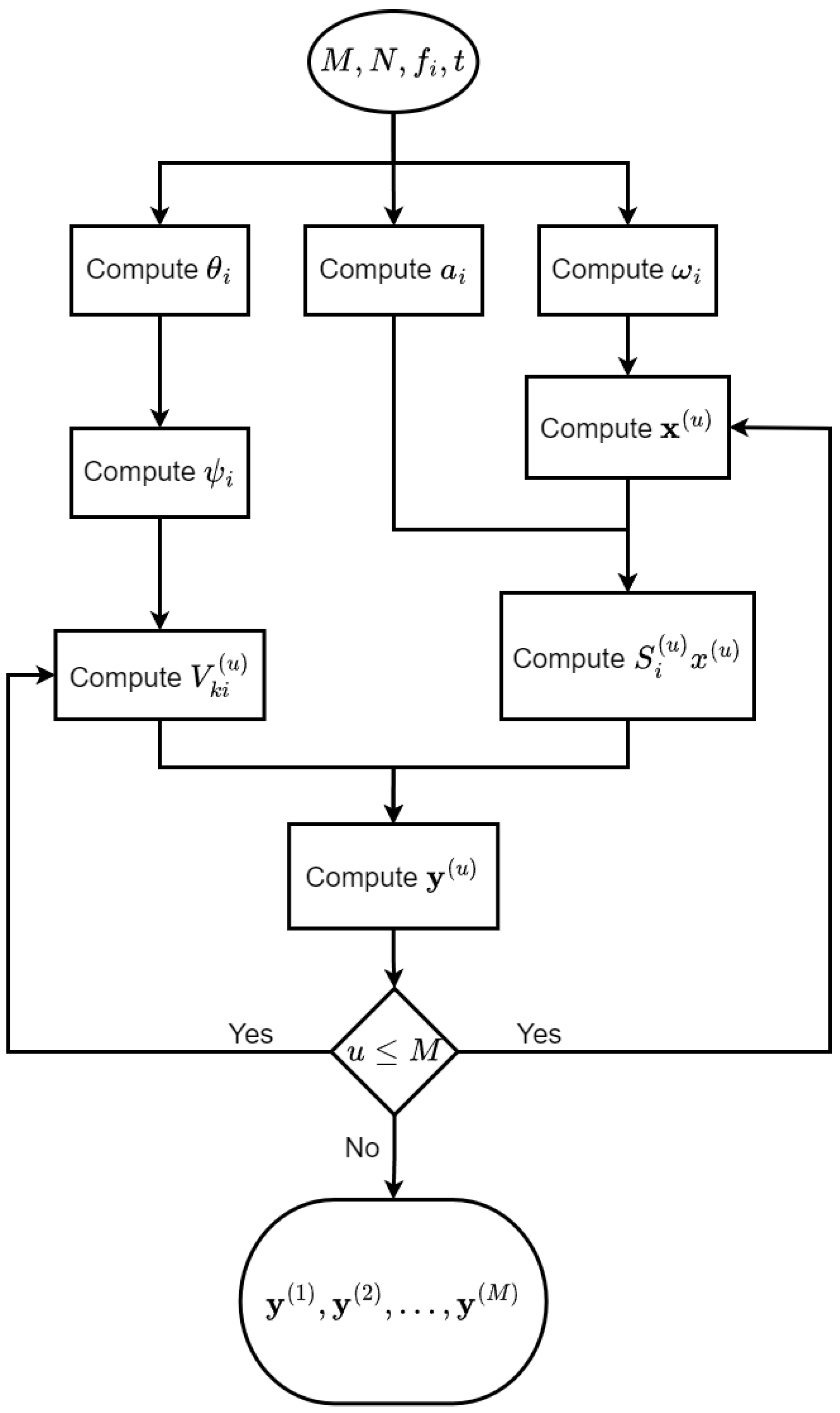
Figure 1. This flowchart depicts the execution of the proposed AUAS swarm routing algorithm followed by the model (1).
Electronics 11 03023 g001
Figure 2. (a) depicts the beamformed signals of the AUAS swarm routing algorithm y ( u ) ( ω i , a i , θ i , t ) over 10 time steps with 0.1 per time step, where each drone u in the circular spatial arrangement is represented along the Drone Index axis, and its N-element antenna array is represented along the Antenna Element Index axis. Note that this figure is not a direct representation of physical space; but rather summarizes results from the perspective of many drones in a single figure, with each drone’s data stacked along the Drone Index axis, and (b) illustrates signals corresponding to the output of the ground-truth activation function γ u , i , k t over 10 time steps with 0.1 per time step.
Electronics 11 03023 g002
Figure 3. A comparison between the beamformed output of the proposed AUAS swarm model and ground-truth bluevalues having a different number of drones and different numbers of elements in the antenna array in the spatial arrangement specified in the results section at t = 0. blue Subfigures (ah) show the 2D projections of 3D views of the 8-beamformed signals of 8-element antenna arrays in 8, 32, 128, or 256 drones vs. the ground-truth signals at time t. Subfigures (il) show the 2D projections of 3D views of the 16-beamformed signals of 16-element antenna arrays in 128, or 256 drones vs. the ground-truth signals at time t.
Electronics 11 03023 g003
Figure 4. Using the code written in Python: (a) shows the number of algorithmic multiplications involved in computing the non-optmized AUAS algorithm; (b) shows the number of algorithmic additions; (c) shows the number of algorithmic multiplications on a log-scaled graph; and (d) shows the number of algorithmic additions on a log-scaled graph of the proposed AUAS swarm routing algorithm. Each line in the subfigures (ad) shows the number of elements in the antenna arrays which are 64, 32, 16, 8, and 4, and varies from top to bottom, respectively.
Electronics 11 03023 g004
Figure 5. Using the code written in Python: (a) shows the execution time; and (b) shows the execution time on a log-scaled graph. Each line in the subfigures (a) and (b) shows the number of elements in the antenna arrays which are 64, 32, 16, 8, and 4, and varies from top to bottom, respectively.
Electronics 11 03023 g005
Figure 6. This shows the BER of the proposed AUAS swarm routing algorithm over a collection of signal-to-noise ratios (expressed as E b / N 0 , where E b is the energy in one bit (Joules) and N 0 is the noise power spectral density (Watts per Hertz)). The x-axis and y-axis represent a collection of signal-to-noise ratios measured in decibels and BER on a logarithmic scale, respectively.
Electronics 11 03023 g006
Figure 7. We show how the beamformed output of the AUAS swarm routing model diverges from the ground-truth signal, especially based on a large number of elements in the antenna arrays, i.e., N = 256 (to show the worst possible case): (a) shows the expected ground-truth signal; (b) shows the imaginary component of the beamformed output signal; (c) shows the differences in (a) and (b); and (d) shows the magnitude of the difference between (a) and (b).
Electronics 11 03023 g007
Publisher’s Note: MDPI stays neutral with regard to jurisdictional claims in published maps and institutional affiliations.