Article

RI-MFM: A Novel Infrared and Visible Image Registration with Rotation Invariance and Multilevel Feature Matching

National Demonstration Center for Experimental Electrical, School of Electronic and Information Engineering, Changchun University of Science and Technology, Changchun 130022, China
*
Author to whom correspondence should be addressed.
Electronics 2022, 11(18), 2866; https://doi.org/10.3390/electronics11182866
Submission received: 28 August 2022 / Revised: 5 September 2022 / Accepted: 8 September 2022 / Published: 10 September 2022
(This article belongs to the Special Issue Multimodal Signal, Image and Video Analysis and Application)

Abstract

:
In the past ten years, multimodal image registration technology has been continuously developed, and a large number of researchers have paid attention to the problem of infrared and visible image registration. Due to the differences in grayscale distribution, resolution and viewpoint between two images, most of the existing infrared and visible image registration methods are still insufficient in accuracy. To solve such problems, we propose a new robust and accurate infrared and visible image registration method. For the purpose of generating more robust feature descriptors, we propose to generate feature descriptors using a concentric-circle-based feature-description algorithm. The method enhances the description of the main direction of feature points by introducing centroids, and, at the same time, uses concentric circles to ensure the rotation invariance of feature descriptors. To match feature points quickly and accurately, we propose a multi-level feature-matching algorithm using improved offset consistency for matching feature points. We redesigned the matching algorithm based on the offset consistency principle. The comparison experiments with several other state-of-the-art registration methods in CVC and homemade datasets show that our proposed method has significant advantages in both feature-point localization accuracy and correct matching rate.

1. Introduction

At present, there are more and more types of imaging sensors, and people can obtain images of multiple bands of the same scene for research [1,2]. The images of multiple bands can perform multi-dimensional analysis on the target, and the obtained information is also more comprehensive. One of the most popular topics in vision is multimodal image registration; in particular, infrared and visible image registration is the most studied [3,4]. Since infrared and visible images can provide complementary information, they have wide applications in image fusion [5,6], automatic transform detection [7], and super-resolution reconstruction [8].
In the past decade, researchers have proposed a large number of infrared and visible image registration methods [9,10]. However, since infrared and visible images belong to two wavelength bands, and the resolutions of the two images are different, the registration is difficult. At present, the existing registration methods are mainly divided into two categories, one is a region-based registration method, and the other is a feature-based registration method.
Area-based infrared and visible image registration methods do not require the extraction of salient features. Matching is performed by directly comparing and matching the intensity difference between two images [11]. Specifically, normalized cross-correlation (NCC) [12] and mutual information (MI) [13,14] in region-based registration methods are used to detect the matching accuracy of image pairs. In some cases, this kind of method can obtain higher matching accuracy, but the whole algorithm is computationally difficult and time-consuming. In particular, MI works well for infrared and visible image registration because of its statistical dependence between the two images. However, MI is prone to fall into local extrema during optimization iterations, which also reduces its robustness and applicability.
The feature-based infrared and visible image registration method is mainly divided into three steps, namely, feature extraction, feature description and feature matching [15]. Feature extraction means that point, line and area features in infrared and visible images are extracted for subsequent feature description and matching. At present, the more advanced feature-extraction algorithms are SURF [16] and SIFT [17]. Nowadays, there are many scholars who use improved SIFT for feature extraction based on the SIFT algorithm. Ye et al. [18] proposed a real-time adaptive registration algorithm for infrared and visible images using morphological gradients and C_SIFT. Feature description refers to generating a vector of a specific dimension for the extracted feature points. This vector should have sufficiently strong rotation and scale invariance. Xiong et al. [19] proposed a rank-based local self-similarity (RLSS) descriptor. This descriptor is robust to nonlinear radiation differences. Feature matching is performed to establish the correct correspondence between the feature descriptors of two images. There can be a large number of false matching points in the initial matching-point set, and researchers most commonly use random sampling consistency (RANSAC) [20] to eliminate the false matching points. However, there is often a gradient inversion problem in infrared images, which leads to a serious mismatch of the established feature descriptors. Last but not least, the existing image registration methods have high computational complexity, and real-time registration is difficult. This also limits the application of registration algorithms in real-time registration scenarios.
To solve the problems raised above, this paper proposes an infrared and visible image-registration method with rotation invariance and multi-level feature matching. First, we preprocess the source image. The source images are converted to grayscale and maintain the same resolution. Second, we use the Canny [21] algorithm to detect the edge features of the image. Two sets of the feature points of the infrared and visible images are obtained. Third, we use a feature-description algorithm based on concentric circles to generate feature descriptors corresponding to two sets of feature points. Fourth, we use a multi-level feature-matching algorithm with improved offset consistency to match feature points. We evaluate the registration performance of the proposed method on public and homemade infrared and visible datasets, and compare with several state-of-the-art registration methods. The experimental results show that the registration method proposed by us has great advantages in the localization accuracy and matching accuracy of feature points. The main contributions of this paper are as follows:
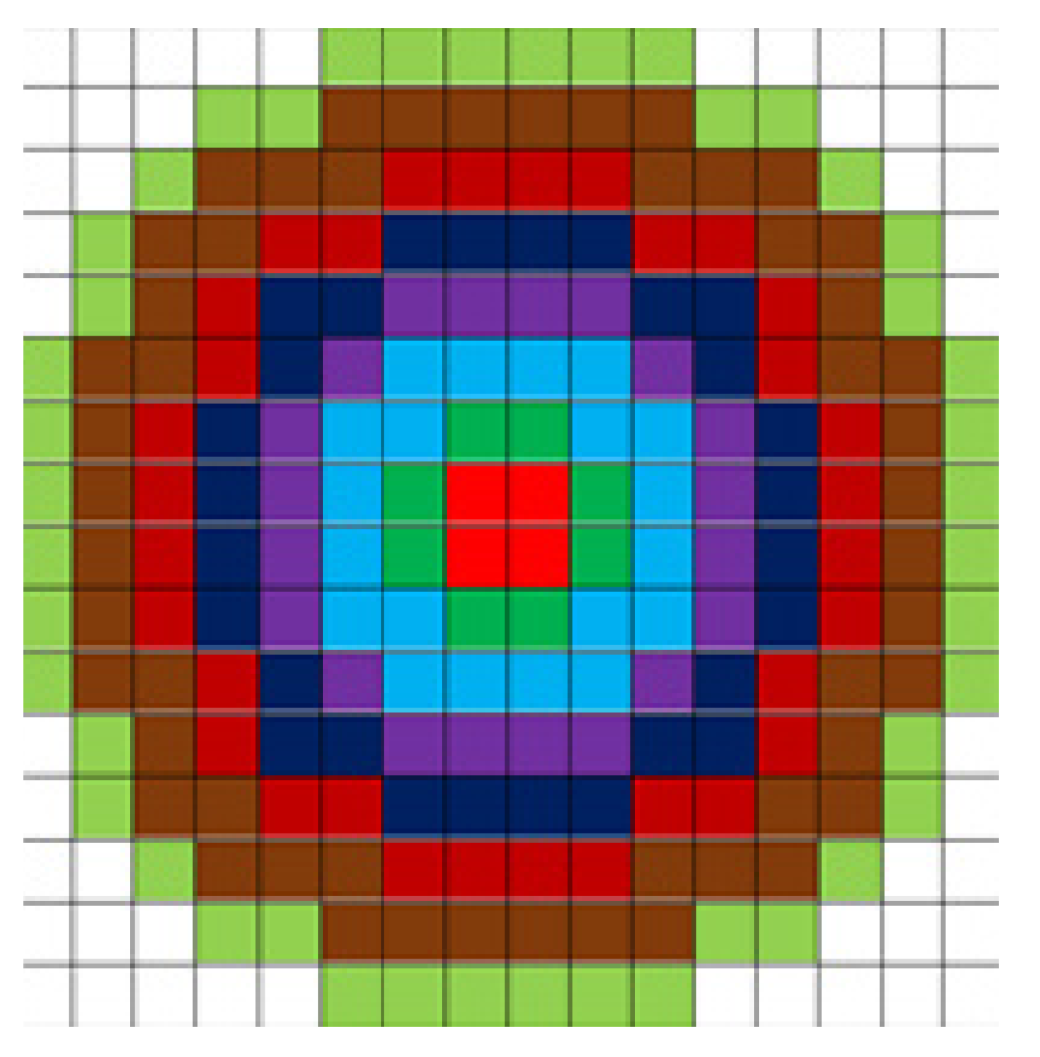
  • We propose to generate feature descriptors using a concentric circle-based feature-description algorithm. When the feature descriptor is generated, the description of the main direction of the feature point is enhanced by introducing the centroid, and the rotation invariance is guaranteed by using the concentric circles. This produces more robust feature descriptors and reduces dimensionality, speeding up computation.
  • We propose a multi-level feature-matching algorithm with improved offset consistency to match feature points. We use the length and angle of the connection between the correct matching points to be basically the same, and redesign the matching algorithm to achieve a better matching effect. Finally, the matching points with higher positioning accuracy can be obtained by iterative screening using the RANSAC algorithm.
  • Experimental results of our proposed infrared and visible image registration method on public and homemade datasets show that it achieves higher localization accuracy and correct matching rate than existing state-of-the-art image registration methods.

2. Related Work

Infrared and visible image registration is a multimodal image registration problem [22,23], since infrared images and visible images provide complementary information, respectively. Therefore, these two kinds of images are heavily used in vision applications (image fusion and image stitching) [24,25,26,27]. However, due to the difference in band and resolution between infrared and visible sensors, the two images cannot be directly fused. We need to register the images of both bands and then fuse them. Currently, existing multimodal image registration methods are mainly divided into two categories, namely, region-based image registration [28,29] and feature-based image registration [30,31]. The two methods are described below.

2.1. Region-Based Methods

Region-based methods utilize the intensity information of images to achieve image registration [32]. Specifically, first, region-based methods find suitable similarity measures in two images. Then, the geometric transformation model is estimated. Finally, iterative optimization is performed on the above similarity measure and transformation parameters are set. However, this method requires a lot of computation. Moreover, it is easy to fall into local minima during the optimization process.
Similarity measurement is an important part in the iterative optimization process of infrared and visible image registration. At present, the similarity measures commonly used by researchers include the sequential similarity detection algorithm [33], mutual information (MI) [13,14,34], normalized cross-correlation (NCC) [12,35], sum of squared differences (SSD) [36] and sum of absolute differences (SAD) [37]. Researchers found that MI is more robust to nonlinear radiation differences and has been used in infrared and visible image-registration methods. Cole-Rhodes et al. [38] improved the joint histogram of MI and proposed a simultaneous perturbation stochastic approximation algorithm for image registration. The algorithm calculates the global optimal value of the local extreme value of the loss function, which greatly speeds up the image-registration speed. To address the problem of insufficient image overlap regions in MI, Xu et al. [39] proposed using Jeffrey divergence as a similarity measure. The registration method using Jeffrey divergence can provide a larger search space.
Another important step in region-based image-registration methods is the geometric transformation model. Multimodal images are warped and resampled by estimating the parameters of the transformation model. Finally, the alignment and registration of the multimodal images are completed. Choosing an appropriate transformation model can speed up iteration and optimization while also improving registration accuracy. Currently, most researchers use linear and nonlinear transformation models for image registration [40].
Through the above two steps, the similarity measure and transformation model are determined. Finally, to obtain the best image registration, region-based image-registration methods also need a way to find the optimal transformation in the solution space. The accuracy of image registration is directly determined by the optimization method. Hasan et al. [41] proposed to use partial volume interpolation to optimize the computation of the gradient of the similarity measure. To avoid the iterative optimization process falling into local optima, Yan et al. [42] proposed to use transfer optimization to maximize MI.

2.2. Feature-Based Methods

The feature-based image-registration method performs registration by extracting geometric features in the image. The geometric features include point, line and region features [43].
At this stage, feature-based image-registration methods are mainly divided into three steps, namely, feature extraction, feature description and feature matching. At present, the feature detection and extraction used by researchers mainly focuses on the corners or curves in the image. Commonly used corner and curve feature-detection algorithms are Harris [44], SIFT [17], Canny [22] and Sobel [45]. Moravec et al. [41] developed a Harris corner detector using image gradients and proposed a response function. The Harris corner feature has rotation invariance, and is relatively stable in detecting changes in image contrast and brightness. Lowe et al. [17] proposed the SIFT algorithm. The features extracted by the SIFT algorithm have strong stability in the case of translation, rotation and scale changes. In order to obtain more useful information, Huang et al. [22] proposed to use the Canny operator to extract edge features in images, and to dilate these edge features.
Between two images, it is difficult to construct the correspondence between features only with the position information of feature points. Therefore, we need to construct a suitable feature descriptor for each feature point, which will be beneficial to the feature-matching process later. In general, the generated feature descriptors are required to be robust to changes in the geometry, appearance, and quality of the image. Moreover, two matching feature descriptors are required to have a close intra-class distance, and two mismatched feature descriptors are required to have a large inter-class distance. At present, for multi-modal images such as infrared and visible, researchers need to make targeted designs and perform optimization according to the characteristics of such images. Chen et al. [46] proposed a multimodal image-registration method based on edge features and scale-invariant PIIFD. They employ the scale-invariant PIIFD algorithm to describe the extracted edge salient features.
Feature matching establishes the correct correspondence between the two sets of extracted feature points. The matching-point pairs of all features include correct matching-point pairs and incorrect matching-point pairs. How to eliminate the wrong matching point pairs is the key to matching. Currently, the most used method by researchers is RANSAC [20], to remove mismatched points. To eliminate the need for artificially set inner point thresholds in RANSAC, Daniel et al. [47] proposed a threshold consistency registration method (MAGSAC). The method proposes the use of an iterative stopping condition based on marginalization. By using threshold consistency, MAGSAC does not require artificially defined interior-point thresholds and can significantly improve the accuracy of robust estimation.

3. Proposed Method

Our proposed infrared and visible image-registration algorithm (RI-MFM) has four key steps, as shown in the flowchart in Figure 1. First, to make the source image more suitable for computer analysis and processing, the use value of the image is improved. We preprocess the source image to enhance edge and texture details in the image. Secondly, in order to extract the robust feature points in the infrared and visible images, we use the Canny algorithm to extract the edge of the preprocessed image, and use the SIFT algorithm to extract the feature-point information in the edge contour. Then, we propose generating feature descriptors using a concentric-circle-based feature-description algorithm. Finally, to achieve more precise matching accuracy and faster matching speed, we propose to use a multi-level feature-matching algorithm with improved offset consistency to match feature points. We will describe each step-in detail, next.
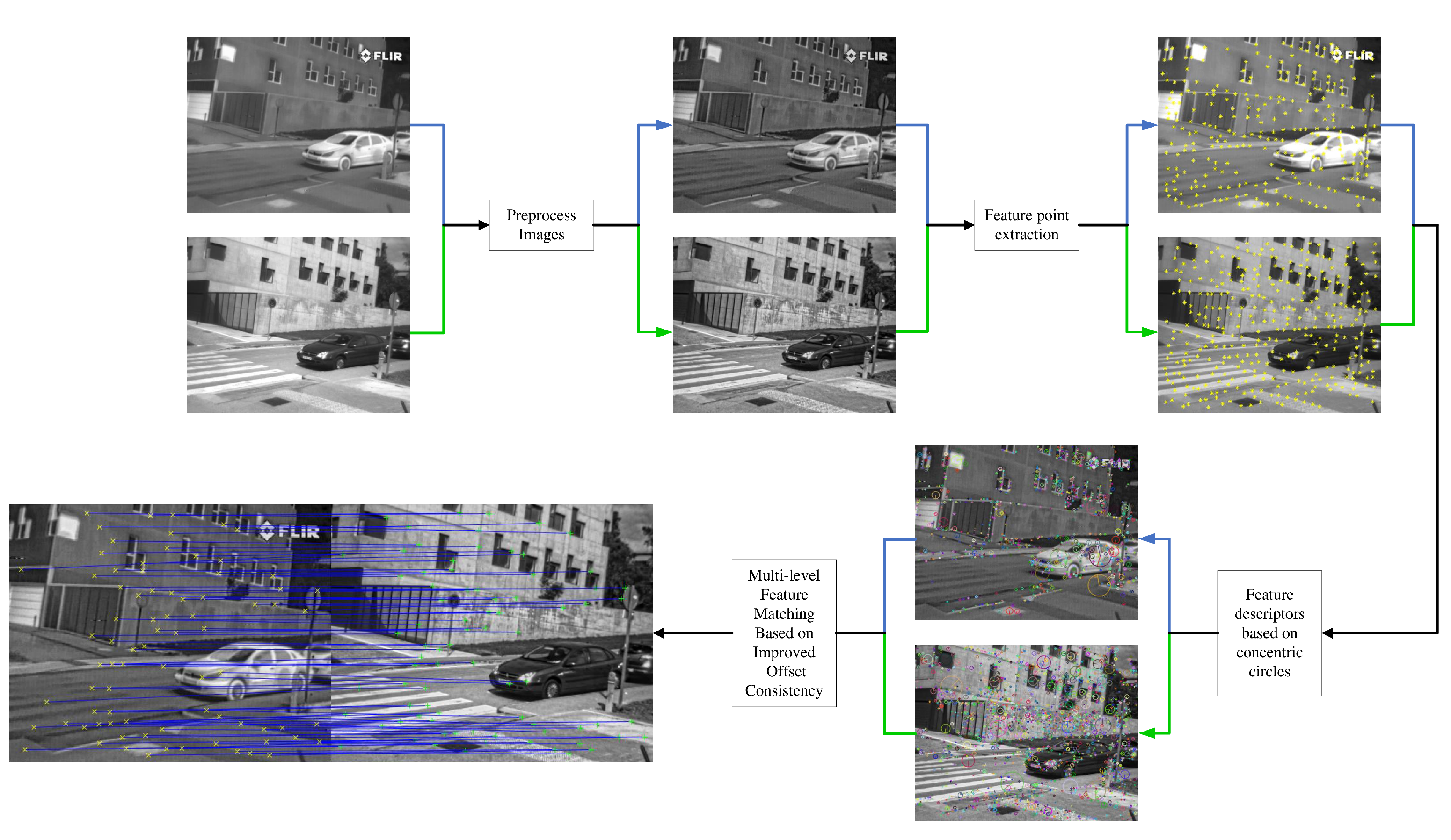
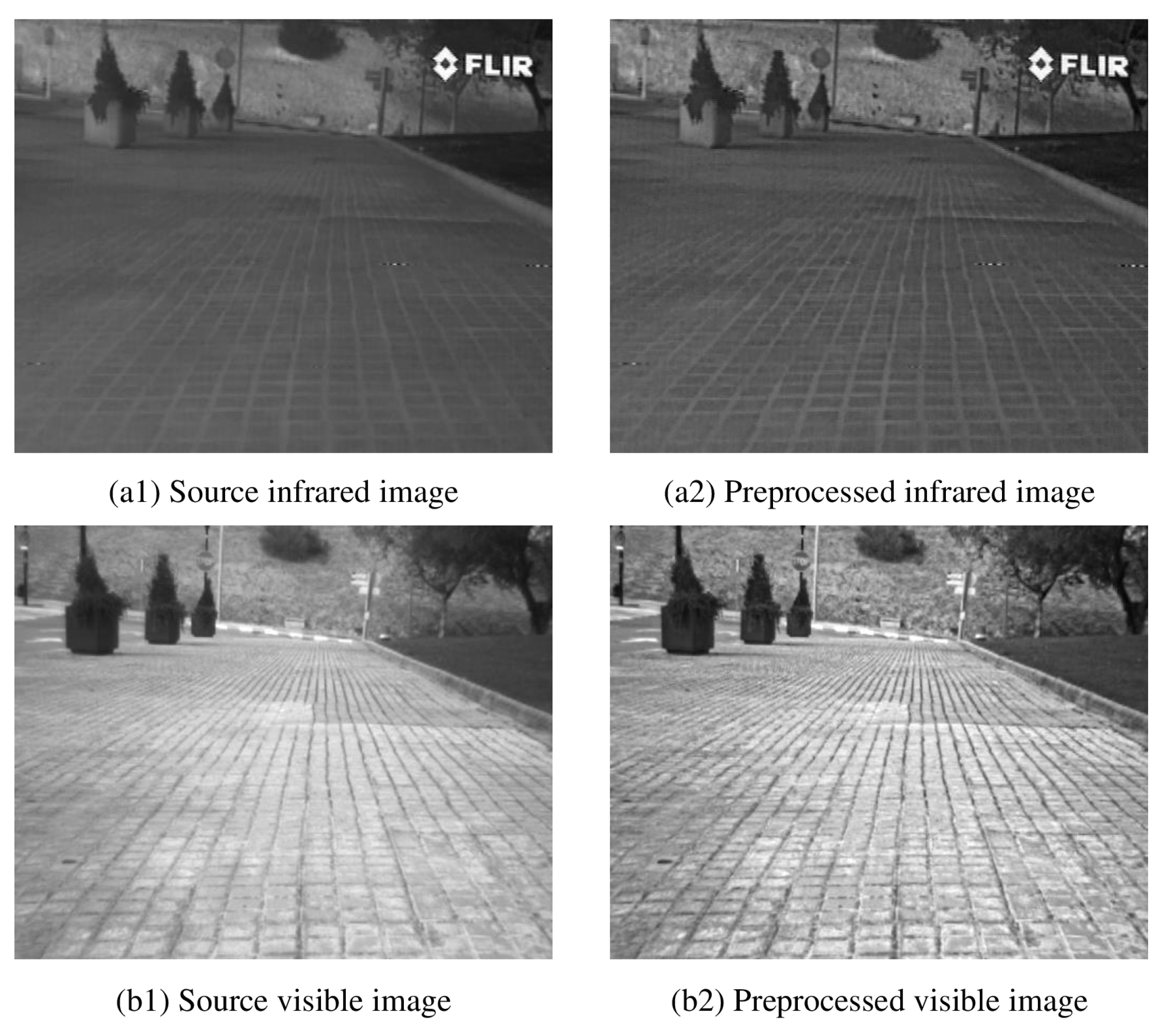
  • Image pre-processing: For better robustness and generalization of the proposed registration algorithm, the input infrared and visible images should be pre-processed. First of all, if the device acquires color images, the color images need to be converted to grayscale images. Then, the infrared image is noise-reduced and dynamic range adjusted using an image-enhancement algorithm, which aims to enhance the edge and texture detail information of the image. Finally, the infrared and visible image resolutions are scaled to the same size.
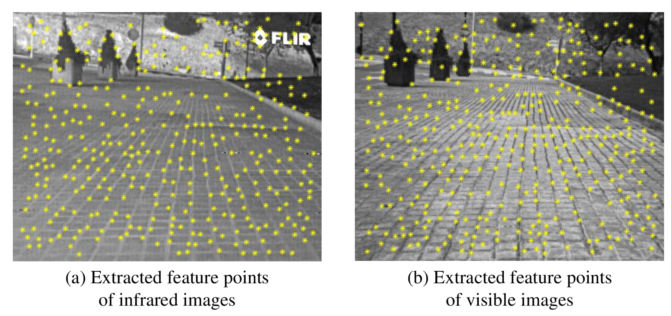
  • Feature extraction: At first, the Canny edge-detection algorithm is used to obtain the edge contour maps of infrared and visible images. Additionally, then, the SIFT algorithm is used to detect and localize the edge contour map. Finally, two sets of feature-point sets of infrared and visible images are obtained.
  • Feature description based on concentric circles: After obtaining two sets of feature points of infrared and visible images, it is necessary to construct corresponding feature descriptors for each feature point. First, the centroid is calculated using the area-integration method. Then, based on the coordinates of the centroid and the feature point, the principal direction is calculated. Finally, the concentric-ring area is constructed to generate the feature-point descriptors.
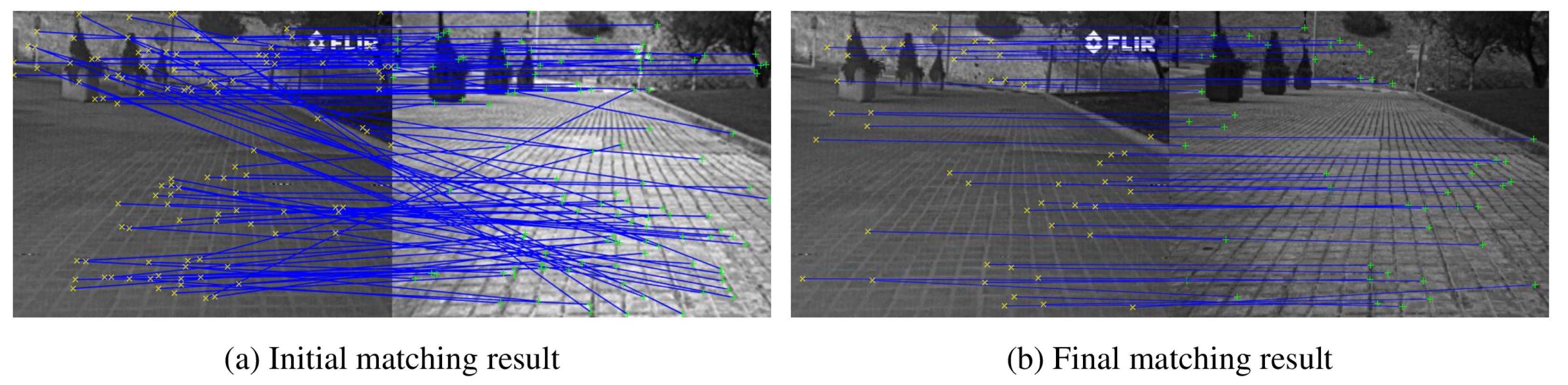
  • Multi-level feature matching based on improved offset consistency: The most important feature of feature matching is to search for the most correct matching-point pair in the two images according to the obtained feature descriptor and determine whether it is a feature point in the same scene. Firstly, coarse matching of feature points is performed using Euclidean distance. After that, the feature points are finely matched using an improved offset consistency judgment criterion to further eliminate the incorrect matches. Finally, in order to eliminate the incorrect matching points with insignificant differences among the candidate matching points, the RANSAC algorithm is used for iterative screening to obtain matching points with higher accuracy.

3.1. Image Preprocessing

Image preprocessing can improve the visual effect of images. At the same time, it can be converted into a form more suitable for machine analysis processing. The preprocessed image can significantly improve the use value of the image. As the source image has problems such as too-concentrated grayscale information, an unclear edge texture and weak contrast, we used a weighted guided filtering algorithm to enhance the source image. First, we layered the source image through multi-scale weighted guided filtering with steering kernels to obtain multiple detail-layer images and base-layer images with detailed information. Secondly, the detail layer was enhanced using Markov–Possion-based maximum a posteriori probability algorithm [48] and Gamma [49] correction algorithm. Then, a contrast-limited adaptive histogram equalization algorithm was applied to the base layer for contrast stretching. Finally, linear fusion was performed to obtain the enhanced image. The image after preprocessing was completed as shown in Figure 2.
The formula of multi-scale weighted guided filtering is defined as:
B = S K W G I F ( F ) I = F B I 1 = S K W G I F ( I ) I 2 = I I 1
where S K W G I F is a weighted guided filtering algorithm with guided kernel [50], F is the input source image, B is the base-layer image obtained after filtering, I is the detail-layer image obtained by the first filtering, I 1 is the detail-layer image obtained by the second filtering, and I 2 is the second layer of detail image obtained by subtracting I 1 from I.

3.2. Feature Detection

Due to the large difference in detail texture between infrared and visible images, features such as grayscale and gradient of a single pixel are not stable between infrared and visible images. However, features such as edges and contours of the target are similar in performance and relatively stable between images. Therefore, we first use the Canny [22] algorithm to extract edge-contour information in infrared and visible images, and then use SIFT [17] to detect and locate feature points on the contour map. The effect after the feature detection is completed is shown in Figure 3. The specific steps are described below.
First, the image is denoised using Gaussian filtering. Secondly, the Sobel [45] operator is used to calculate the gradient magnitude and argument of the image, and non-maximum suppression is used to eliminate some non-edge points, so that the detection of edge pixel positions is more accurate. Then, the disconnected parts in the thin lines are connected by the double threshold method, which is the required edge-contour feature. Finally, SIFT [17] feature-point detection and localization are performed on the contour map to obtain two sets of feature-point sets of infrared and visible images.

3.3. Feature Description

Between infrared and visible images, it is difficult to construct the correspondence of feature points only by the position information of feature points. Therefore, we need to construct a suitable feature descriptor for each feature point, which is conducive to better matching operations. To improve the accuracy of the descriptors, we introduce centroids and concentric circles in the feature descriptors. At the same time, this can enhance the rotation invariance of the feature descriptor and reduce the algorithm complexity.
First, the centroid is calculated using the area integration method. In the scale space corresponding to feature point P ( x i , y i , σ ) , each pixel is regarded as a square of 1 × 1 . Take the feature point P ( x i , y i ) as the center of the circle and 3 σ as the radius to make a circular area. Definition: The overlapping area of each pixel and the circular area is the area integration coefficient C x y of the pixel. When the pixel is completely contained within the circular area, the overlap-area value is 1. The corresponding area integration coefficient C x y is 1. The centroid coordinate is the coordinate x j , y j of the pixel. When there is a partial overlap, the area-integration coefficient C x y of the pixel is the area value of the overlapped part. The centroid coordinate x j , y j corresponding to the pixel can be obtained through the calculation method of the geometric centroid.
Second, according to the coordinates of the centroid and the feature point, the main direction is calculated. The image moment of feature point P m n can be calculated from the area-integration coefficient and centroid coordinates of each pixel.
P m n = C x y x j m y j n G ( x , y )
where G ( x , y ) is the gray value corresponding to ( x , y ) , and m , n is the order corresponding to x , y ; the values are, respectively, 0 or 1. Therefore, P 00 , P 01 , and P 10 can be obtained. The brightness centroid coordinates of the circular area of the feature point P ( x i , y i ) is L ( x k , y k ) . It is calculated as follows:
L ( x k , y k ) = P 10 P 00 , P 01 P 00
Definition: The angle θ 1 between the direction vector O L of the circular area and the X axis is the main direction of the feature point. θ is calculated as follows:
θ = a r c t a n y k y i x k x i
Third, concentric annular regions are constructed and feature-point descriptors generated. Taking the feature point P ( x i , y i ) as the center of the circle, the coordinate axis was rotated to coincide with the main direction. A concentric annular region of radius 8 was constructed, as shown in Figure 4. The gradient magnitude and argument for each pixel were calculated using the following equations.
A ( x , y ) = ( M ( x + 1 , y ) M ( x 1 , y ) ) 2 + ( M ( x , y + 1 ) M ( x , y 1 ) ) 2
θ 2 = a r c t a n M ( x , y + 1 ) M ( x , y 1 ) M ( x + 1 , y ) M ( x 1 , y )
where A ( x , y ) , θ 2 and M x , y represent the magnitude of the gradient, the argument direction of the pixel point and the gray value of the pixel point, respectively.
Each feature point corresponds to a concentric annular region. The rings of each color form a sub-area. First, the gradient values of all pixels within the first annular region are calculated. The accumulated gradient values are counted in 8 directions (0°∼360° is evenly divided into 8 intervals) to generate an 8-dimensional vector. Then, to make the gradient accumulation with the largest value as the head of the feature vector, the gradient accumulation value is processed by using the maximum value circular shift. We can obtain the 1st to 8th vectors of the feature descriptor. Finally, the gradient-accumulation values in each direction are obtained by calculating the other regions of each circle separately using the above approach. A total of 8 × 8 = 64 -dimensional vectors are generated as descriptors of feature points. The use of concentric rings to compute the descriptors of feature points ensures that the relative information remains unchanged when the vectors are rotated, and also facilitates the subsequent computation of feature matching.

3.4. Feature Matching

In point-based registration methods, feature matching is the most important step, which directly determines the accuracy of image registration. Feature matching is to establish the correct correspondence between two sets of feature points. Due to the difference in band and resolution between the infrared image and the visible image, there is a certain deviation in the position of the extracted feature points. Therefore, in order to obtain matching points with higher localization accuracy, we propose the RI-MFM feature-matching method.
Suppose the set of feature-point coordinates extracted from the infrared image is I = ( i 1 , , i K ) T , and this set is a K × 2 -dimensional matrix. The set of feature-point coordinates extracted from the visible image is V = ( v 1 , , v L ) T , and this set is a L × 2 -dimensional matrix; K and L are not necessarily equal. The feature points extracted from the two images have their own feature descriptors.
First, the Euclidean distance between each pair of feature descriptors is calculated and the ratio between the nearest neighbor and the next neighbor Euclidean distance is compared with the set threshold to determine whether it is a valid matching pair. The feature point whose coordinates are i K is selected, and the Euclidean distance between all the feature points in the point set V and the given point calculated. The closest point is recorded as v m 1 , and the distance of the feature point is recorded as d m 1 . The next closest point is recorded as v m 2 , and the distance between feature points is recorded as d m 2 . The distance ratio between the closest and the next closest feature points is defined as:
R = d m 1 d m 2
Obviously, R 1 . The smaller the value of R, the greater the difference between the nearest neighbor distance and the second neighbor distance.
Therefore, it can be shown that the similarity between feature points i K and v m 1 is very high, and the possibility of correct matching is high. On the contrary, it means that the similarity between the feature points x K and v m 1 is not high, and it is most likely not a valid match. Firstly, whether it is a valid match is judged by setting a reasonable threshold. We set the threshold R to 0.8.
Then, the improved offset consistency theory is introduced. Suppose two pairs of IR and visible image matching points are given, I 1 ( x 1 , y 1 ) , I 2 ( x 2 , y 2 ) and V 1 ( m 1 , n 1 ) , V 2 ( m 2 , n 2 ) , respectively. If the following equation is satisfied, the two pairs of matching points are considered as correct matching points.
θ I 2 , V 2 θ I 1 , V 1 × d I 2 , V 2 d I 1 , V 1 T
where T is a manually set threshold constant, θ I i , V i , i = 1 , 2 and d I i , V i , i = 1 , 2 are calculated as follows.
θ I i , V i = a r c t a n n i y i m i x i , i = 1 , 2
d I i , V i = ( m i x i ) 2 + ( n i y i ) 2 , i = 1 , 2
Finally, the matching points with higher positioning accuracy can be obtained by iterative screening using the RANSAC algorithm. After the above two steps, most of the erroneous matching points in the candidate matching can be removed. However, a few erroneous matching points with insignificant differences still remain. This part of the wrong matching points accounts for a small proportion of the total matching points. However, to pursue higher matching-point positioning accuracy, we use the RANSAC algorithm for iterative screening to obtain matching points with higher positioning accuracy. The results of the initial matching are shown in Figure 5a. Figure 5b shows the result after optimization by our proposed matching algorithm.

4. Experimental Analysis
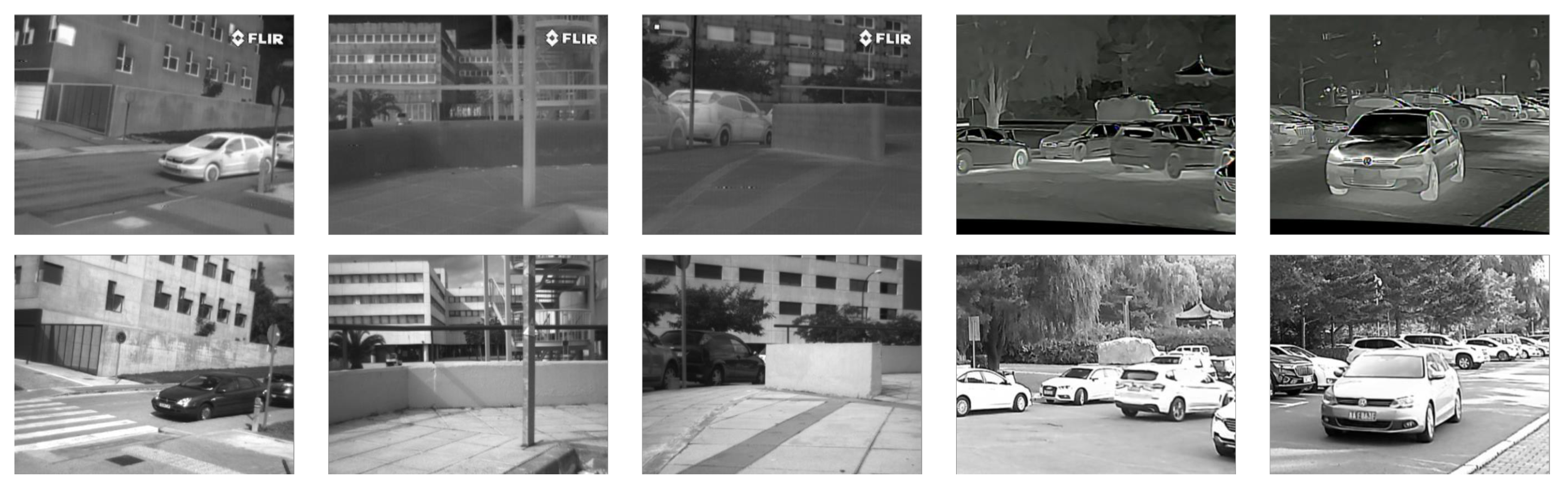
To verify the effectiveness of our proposed registration method, we compare it with three other state-of-the-art infrared and visible image-registration methods. The three methods are: EG-SURF [51], LPM [52] and SI-PIIFD [53]. All comparative experiments were run on the same computer, and the experimental environment was as follows: CPU Intel i7-7820X, RAM 16GB, Windows 10 system.

4.1. Dataset

In experiments, we qualitatively and quantitatively compare four infrared and visible image-registration methods using the CVC Multimodal Stereo Dataset [54] and a homemade dataset. Among them, the CVC Multimodal Stereo Dataset contains 100 pairs of long-wave infrared and visible images with an image resolution of 506 × 408, mainly taken in urban streets. The visible camera model used in the homemade dataset is: MER-031-300GM/C, the resolution is 640 × 480, the focal length is 12 mm, and the HFOV is 22°. The model of the infrared camera is LTWN640, the resolution is 640 × 480, the focal length is 13 mm, and the HFOV is 36°. The homemade dataset contains 50 pairs of long-wave infrared and visible images, which are mainly captured in campus scenes. Figure 6 shows samples from both datasets, where the first three columns are from the CVC Multimodal Stereo Dataset and the last two columns are from the homemade dataset.

4.2. Evaluation Metrics
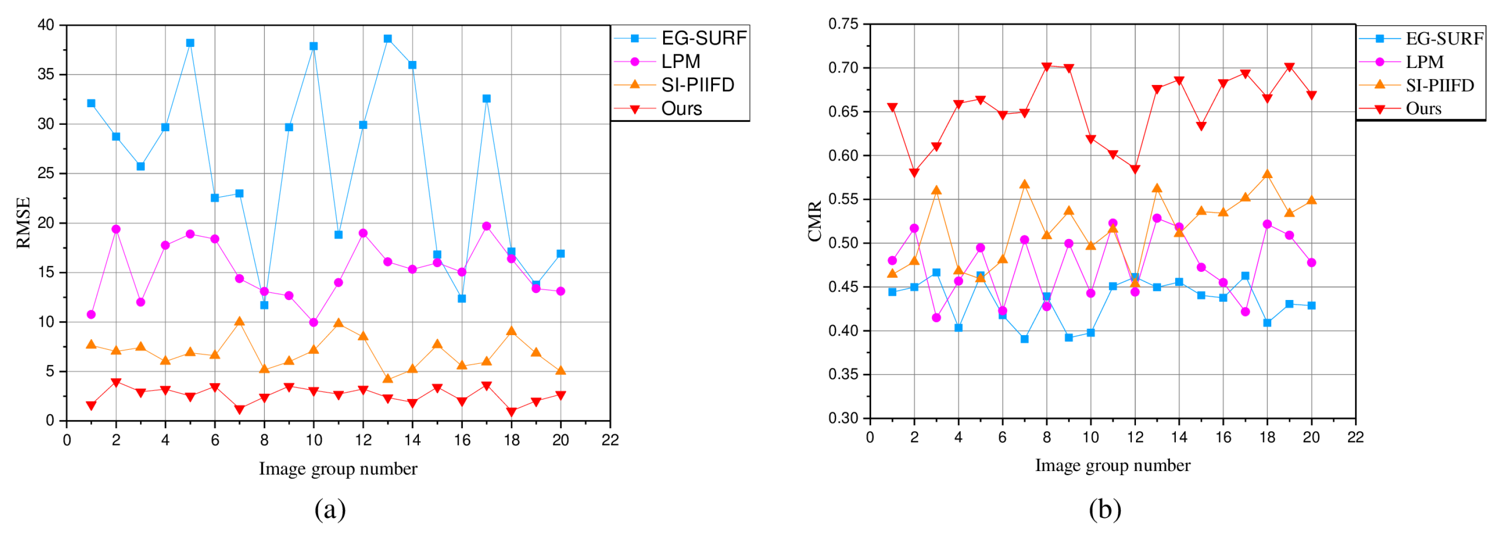
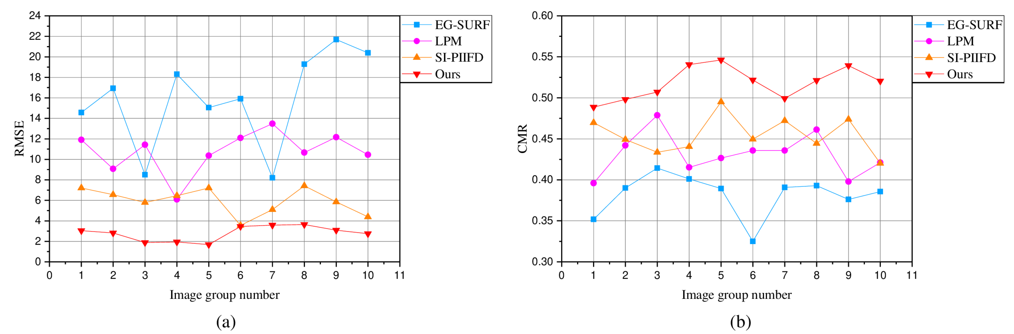
To quantitatively evaluate RI-MLM and three other infrared and visible image-registration methods, we used three evaluation metrics, namely, root mean square error (RMSE) [55], correct match rate (CMR) [56] and average runtime (ART) [57].
  • RMSE
    The RMSE is to detect the positioning accuracy of feature points, and RMSE is defined as:
    R M S E = i = 1 N ( x i x i T ) + ( y i y i T ) 2 N
    where ( x i , y i ) is the infrared image feature-point coordinates, ( x i T , y i T ) is the corresponding visible image theoretical matching point coordinates, and N is the number of matching points.
    To distinguish the location of each pair of matching points in the alignment results, ( x i x i T ) + ( y i y i T ) 2 | 8 is defined as the correct matching point. The rest are false match points.
  • CMR
    To quantitatively evaluate the matching accuracy of the matching method, the CMR evaluation index is introduced. CMR is defined as follows:
    C M R = N C o r r e c t N T o t a l
    where N C o r r e c t is the number of correctly matched feature-point pairs, and N T o t a l is the number of all detected feature-point pairs.
  • ART
    The efficiency of each method is judged by counting the average running time of different infrared and visible image-registration methods on the same experimental platform.

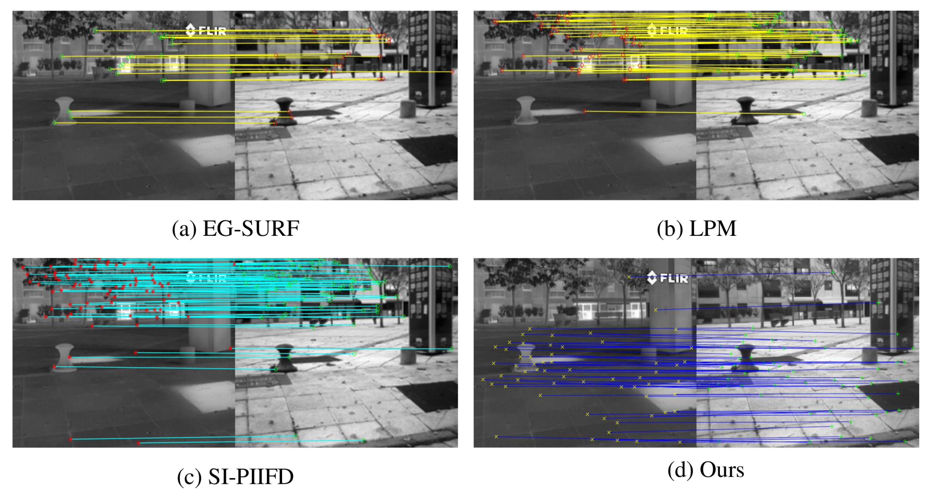
4.3. Experiments on the CVC Dataset

To demonstrate the superiority of our proposed infrared and visible image-registration method, we qualitatively and quantitatively compare the registration performance of the four methods.

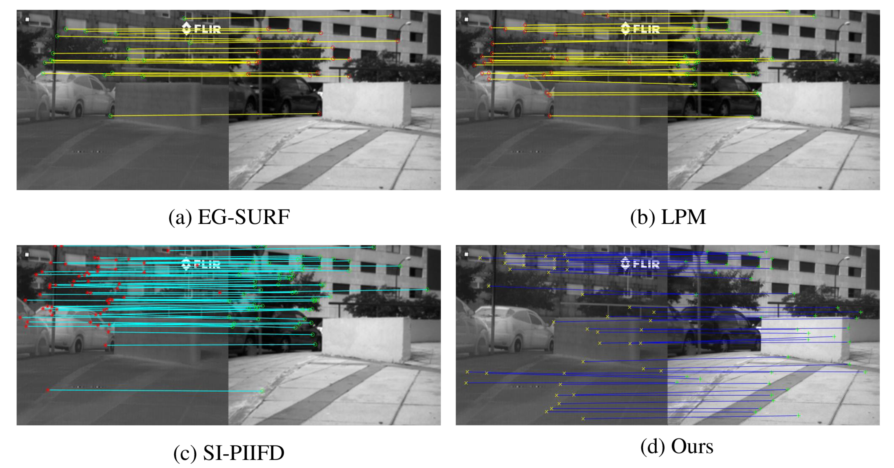
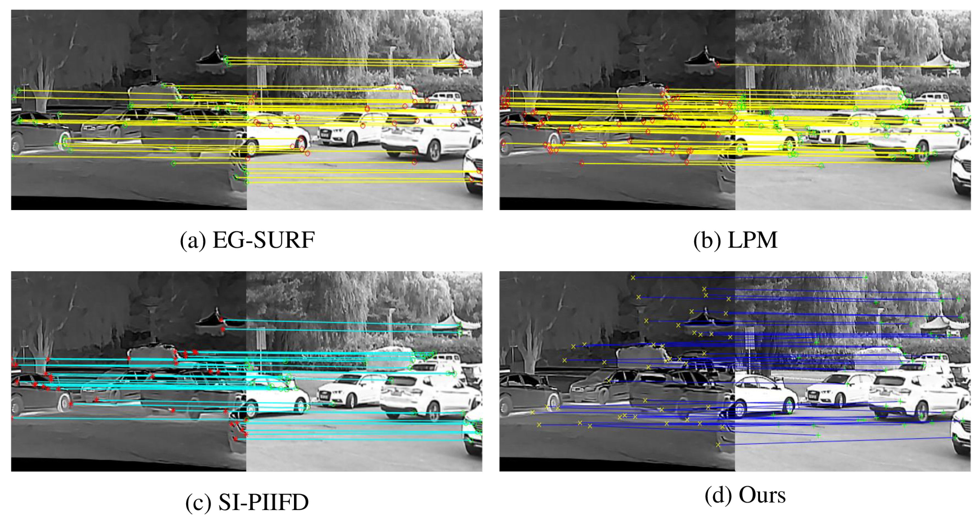
4.3.1. Qualitative Evaluation

We show the feature-point matching results of the four registration methods in Figure 7 and Figure 8. The two pairs of images are from the 11th and 30th pairs of images in the CVC dataset, respectively. The left side of each subplot shows the infrared image and the right side shows the visible image. Figure 7a and Figure 8a are from EG-SURF. It can be seen from the figure that there are fewer feature points obtained by EG-SURF, and most of them are concentrated in the upper part of the image. The matching results of feature points extracted by LPM are shown in Figure 7b and Figure 8b. Compared with EG-SURF, LPM obtains more matching feature points. Figure 7c and Figure 8c are the matching results of SI-PIIFD. SI-PIIFD obtains more matching points, but the distribution of matching points is relatively concentrated, which is not conducive to image alignment. In Figure 7d and Figure 8d, our proposed method obtains the most matching points, and the distribution is relatively uniform. It is more convenient in image-alignment work, and the alignment accuracy of images is higher. As we fully consider the overall difference between infrared image and visible image in the process of feature extraction, the extracted feature points are distributed more and more uniformly in the graph. By using the feature-description method based on concentric circles, the rotation invariance and robustness of feature points are improved. As can be seen from Figure 7d and Figure 8d, the matched feature points correspond strictly.

4.3.2. Quantitative Evaluation

In Figure 9, four registration methods were quantitatively analyzed using RMSE and CMR. Twenty pairs of infrared and visible images were randomly selected from the CVC dataset for analysis. In Figure 9a, we can see that the RMSE values obtained by EG-SURF and LPM are larger, implying lower accuracy of these two registration methods. The RMSE values obtained by SI-PIIFD and our proposed method are relatively close on some image pairs. However, the average RMSE obtained by our proposed method is smaller than that of SI-PIIFD. Therefore, it has higher registration accuracy as we use the feature-description method based on concentric circles to generate robust feature descriptors and improve feature-point location accuracy.
In Figure 9b, the CMR values obtained for EG-SURF, LPM and SI-PIIFD are relatively close, with an average correct match rate close to 50%. However, since we use a multi-level feature-matching method with improved offset consistency, the incorrect matching points are quickly eliminated. As a result, our proposed registration method obtains the highest correct matching rate. It is demonstrated by RMSE and CMR that the accuracy of our proposed registration method is significantly better than the other three.
The average running times (the average time to complete the registration of 20 pairs of images) of the four registration methods are shown in Table 1. The average running time of EG-SURF is the smallest, indicating that this method has the highest registration efficiency. The average running times of LPM, SI-PIIFD and our proposed method are not very different, and the running efficiency of the registration methods is still lacking.

4.4. Experiments on Homemade Datasets

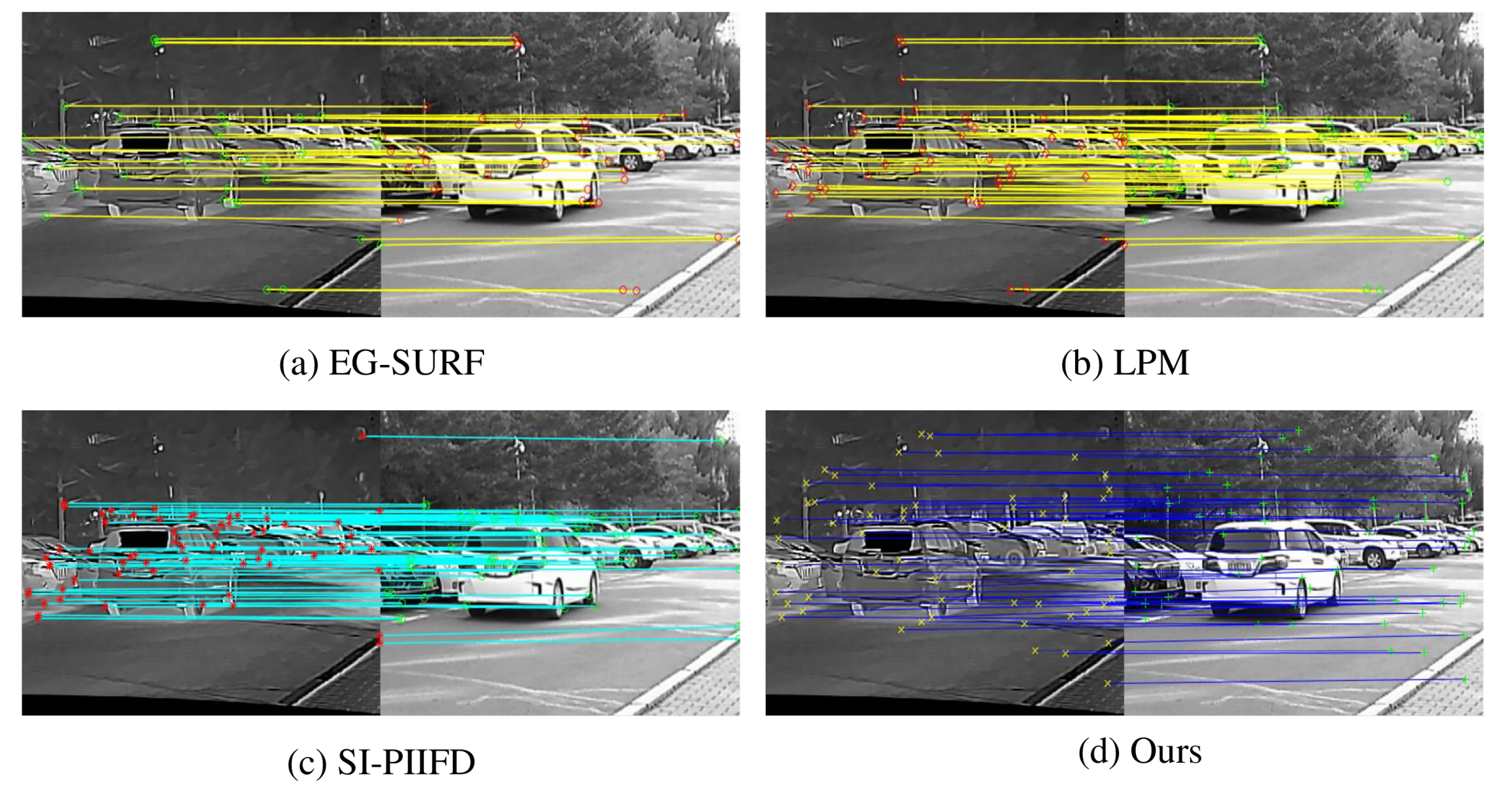
4.4.1. Qualitative Evaluation

In Figure 10 and Figure 11, the registration results of the four registration methods on our homemade dataset are shown, respectively. The two pairs of images are from the 5th and 32nd pairs of images in the homemade dataset, respectively. The left side of each subplot shows the infrared image and the right side shows the visible image. Figure 10d and Figure 11d show the matching results of our proposed registration method. Figure 10a–c and Figure 11a–c show the matching results of the other three methods, respectively. It can be seen from Figure 10 and Figure 11 that EG-SURF and LPM obtain fewer matching points than the other two methods. In addition, the matching points are densely concentrated in the middle of the image, which is more difficult for the subsequent image-registration process. The matching points of SI-PIIFD and our proposed method are more numerous. However, the matching points of our proposed registration method are more evenly distributed throughout the whole image and most of them are located at critical positions in the image. We propose to match feature points using a multi-level feature-matching algorithm with improved offset consistency. The redesigned matching algorithm achieves a better matching effect. As can be seen from Figure 10d and Figure 11d, our proposed registration method performs better on the homemade dataset.

4.4.2. Quantitative Evaluation

Figure 12a,b are the qualitative evaluation results of the four registration methods on the homemade dataset. Figure 12a shows the RMSE values of 10 randomly selected pairs of image-matching points in the homemade dataset. As can be seen from the line Figure 12a, our proposed registration method has a smaller RMSE value compared to the other three registration methods. This also means that the registration point positioning points obtained by our proposed method are more accurate.
The CMR values of the four registration methods are shown in Figure 12b. The CMR value of EG-SURF is the smallest. The CMR values of LPM and SI-PIIFD are relatively close in most cases. It is obvious from Figure 12b that the CMR values of our proposed registration method are significantly improved compared to the other methods. Combining the RMSE and CMR values obtained by the four registration methods, it can be seen that our proposed registration method achieves a better level of localization accuracy and correct matching rate.
Table 2 shows the average running time of the four registration methods to complete the 10-pair image registration on the homemade dataset. The ART value of EG-SURF is the smallest. Therefore, EG-SURF has the highest running efficiency. The ART values of the other three methods are three times larger than the ART values of EG-SURF. Therefore, the other three methods have lower running efficiency and there is more room for optimization.

5. Conclusions

The RI-MFM method proposed in this paper significantly improves the registration accuracy of infrared and visible images. While there are differences in gray distribution and resolution in the source image, the method can accurately and quickly match the extracted effective feature points as we used a concentric-circle-based feature-description algorithm to generate robust feature descriptors. At the same time, a multi-level feature-matching algorithm with improved offset consistency was used in the feature-matching process, which optimizes the positioning accuracy and correct matching rate of matching points. Qualitative and quantitative experimental results on CVC and homemade datasets show that our proposed method performs better than state-of-the-art registration methods.
In the future, we will continue to optimize the computational complexity of the algorithm, speed up the registration speed, and strive to achieve real-time registration as soon as possible. Meanwhile, the RI-MFM method also needs to achieve more complex work in other aspects of multimodal image registration, such as medical and remote-sensing image registration.

Author Contributions

Conceptualization, D.Z.; Data curation, Y.J. and X.X.; Funding acquisition, W.Z.; Investigation, J.F. and R.G.; Methodology, D.Z.; Project administration, W.Z.; Software, D.Z.; Visualization, J.F., Y.J. and Y.C.; Writing—original draft, D.Z.; Writing—review and editing, W.Z. All authors have read and agreed to the published version of the manuscript.

Funding

This work was supported in part by the Jilin Provincial Development and Reform Commission’s special project for innovation ability construction (infrared image super-resolution and detail enhancement system research and development).

Institutional Review Board Statement

Not applicable.

Informed Consent Statement

Not applicable.

Data Availability Statement

The data presented in this study are available on request from the corresponding author.

Conflicts of Interest

The authors declare no conflict of interest.

References

  1. Li, H.; Ding, W.; Cao, X.; Liu, C. Image registration and fusion of visible and infrared integrated camera for medium-altitude unmanned aerial vehicle remote sensing. Remote Sens. 2017, 9, 441. [Google Scholar] [CrossRef]
  2. Dwith Chenna, Y.N.; Ghassemi, P.; Pfefer, T.J.; Casamento, J.; Wang, Q. Free-form deformation approach for registration of visible and infrared facial images in fever screening. Sensors 2018, 18, 125. [Google Scholar] [CrossRef] [PubMed]
  3. Dou, J.; Qin, Q.; Tu, Z. Multi-Modal Image Registration Based on Local Self-Similarity and Bidirectional Matching. Pattern Recognit. Image Anal. 2021, 31, 7–17. [Google Scholar] [CrossRef]
  4. Zhao, X.; Zhang, J.; Yang, C.; Song, H.; Shi, Y.; Zhou, X.; Zhang, D.; Zhang, G. Registration for optical multimodal remote sensing images based on FAST detection, window selection, and histogram specification. Remote Sens. 2018, 10, 663. [Google Scholar] [CrossRef]
  5. Zhu, D.; Zhan, W.; Jiang, Y.; Xu, X.; Guo, R. MIFFuse: A Multi-Level Feature Fusion Network for Infrared and Visible Images. IEEE Access 2021, 9, 130778–130792. [Google Scholar] [CrossRef]
  6. Xiao, R.; Cheng, F.; Shi, J.; Wang, Y.; Li, C. An Infrared and Visible Fusion Framework Based on a Novel Decomposition Method. Symmetry 2022, 14, 786. [Google Scholar] [CrossRef]
  7. Alonso, M.T.; López-Martínez, C.; Mallorquí, J.J.; Salembier, P. Edge enhancement algorithm based on the wavelet transform for automatic edge detection in SAR images. IEEE Trans. Geosci. Remote Sens. 2010, 49, 222–235. [Google Scholar] [CrossRef]
  8. Jiang, Y.; Liu, Y.; Zhan, W.; Zhu, D. Lightweight Dual-Stream Residual Network for Single Image Super-Resolution. IEEE Access 2021, 9, 129890–129901. [Google Scholar] [CrossRef]
  9. Chen, Y.; Zhang, X.; Zhang, Y.; Maybank, S.J.; Fu, Z. Visible and infrared image registration based on region features and edginess. Mach. Vis. Appl. 2018, 29, 113–123. [Google Scholar] [CrossRef]
  10. Ma, Y.; Wang, Y.; Mei, X.; Liu, C.; Dai, X.; Fan, F.; Huang, J. Visible/infrared combined 3D reconstruction scheme based on nonrigid registration of multi-modality images with mixed features. IEEE Access 2019, 7, 19199–19211. [Google Scholar] [CrossRef]
  11. Jhan, J.P.; Rau, J.Y. A generalized tool for accurate and efficient image registration of UAV multi-lens multispectral cameras by N-SURF matching. IEEE J. Sel. Top. Appl. Earth Obs. Remote Sens. 2021, 14, 6353–6362. [Google Scholar] [CrossRef]
  12. Inglada, J.; Giros, A. On the possibility of automatic multisensor image registration. IEEE Trans. Geosci. Remote Sens. 2004, 42, 2104–2120. [Google Scholar] [CrossRef]
  13. Woo, J.; Stone, M.; Prince, J.L. Multimodal registration via mutual information incorporating geometric and spatial context. IEEE Trans. Image Process. 2014, 24, 757–769. [Google Scholar] [CrossRef]
  14. Yang, T.; Tang, Q.; Li, L.; Song, J.; Zhu, C.; Tang, L. Nonrigid registration of medical image based on adaptive local structure tensor and normalized mutual information. J. Appl. Clin. Med. Phys. 2019, 20, 99–110. [Google Scholar] [CrossRef]
  15. Zhang, J.; Wang, Y.; Dai, J.; Cavichini, M.; Bartsch, D.U.G.; Freeman, W.R.; Nguyen, T.Q.; An, C. Two-Step Registration on Multi-Modal Retinal Images via Deep Neural Networks. IEEE Trans. Image Process. 2021, 31, 823–838. [Google Scholar] [CrossRef]
  16. Bay, H.; Tuytelaars, T.; Gool, L.V. SURF: Speeded up robust features. In Proceedings of the European Conference on Computer Vision, Graz, Austria, 7–13 May 2006; pp. 404–417. [Google Scholar]
  17. Lowe, D.G. Object recognition from local scale-invariant features. Proc. Seventh IEEE Int. Conf. Comput. Vis. 1999, 2, 1150–1157. [Google Scholar]
  18. Zeng, Q.; Adu, J.; Liu, J.; Yang, J.; Xu, Y.; Gong, M. Real-time adaptive visible and infrared image registration based on morphological gradient and C_SIFT. J. Real-Time Image Process. 2020, 17, 1103–1115. [Google Scholar] [CrossRef]
  19. Xiong, X.; Xu, Q.; Jin, G.; Zhang, H.; Gao, X. Rank-based local self-similarity descriptor for optical-to-SAR image matching. IEEE Geosci. Remote Sens. Lett. 2019, 17, 1742–1746. [Google Scholar] [CrossRef]
  20. Fischler, M.A.; Bolles, R.C. Random sample consensus: A paradigm for model fitting with applications to image analysis and automated cartography. Commun. ACM 1981, 24, 381–395. [Google Scholar] [CrossRef]
  21. Canny, J. A computational approach to edge detection. In Proceedings of the IEEE Transactions on Pattern Analysis and Machine Intelligence, Kerkyra, Greece, 20–27 September 1986; pp. 679–698. [Google Scholar]
  22. Chen, J.; Cheng, B.; Zhang, X.; Long, T.; Chen, B.; Wang, G.; Zhang, D. A TIR-Visible Automatic Registration and Geometric Correction Method for SDGSAT-1 Thermal Infrared Image Based on Modified RIFT. Remote Sens. 2022, 14, 1393. [Google Scholar] [CrossRef]
  23. Koz, A.; Efe, U. Geometric-and Optimization-Based Registration Methods for Long-Wave Infrared Hyperspectral Images. Remote Sens. 2021, 13, 2465. [Google Scholar] [CrossRef]
  24. Zhu, D.; Zhan, W.; Jiang, Y.; Xu, X.; Guo, R. IPLF: A Novel Image Pair Learning Fusion Network for Infrared and Visible Image. IEEE Sens. J. 2022, 22, 8808–8817. [Google Scholar] [CrossRef]
  25. Son, D.M.; Kwon, H.J.; Lee, S.H. Visible and Near Infrared Image Fusion Using Base Tone Compression and Detail Transform Fusion. Chemosensors 2022, 10, 124. [Google Scholar] [CrossRef]
  26. Xiao, W.; Zhang, Y.; Wang, H.; Li, F.; Jin, H. Heterogeneous Knowledge Distillation for Simultaneous Infrared-Visible Image Fusion and Super-Resolution. IEEE Trans. Instrum. Meas. 2022, 71, 1–15. [Google Scholar] [CrossRef]
  27. Li, Q.; Lu, L.; Li, Z.; Wu, W.; Liu, Z.; Jeon, G.; Yang, X. Coupled GAN with relativistic discriminators for infrared and visible images fusion. IEEE Sens. J. 2019, 21, 7458–7467. [Google Scholar] [CrossRef]
  28. Xie, X.; Zhang, Y.; Ling, X.; Wang, X. A new registration algorithm for multimodal remote sensing images. In Proceedings of the IGARSS 2018-2018 IEEE International Geoscience and Remote Sensing Symposium, Valencia, Spain, 22–27 July 2018; pp. 7011–7014. [Google Scholar]
  29. Zabalza, J.; Ren, J.; Zheng, J.; Zhao, H.; Qing, C.; Yang, Z.; Du, P.; Marshall, S. Novel segmented stacked autoencoder for effective dimensionality reduction and feature extraction in hyperspectral imaging. Neurocomputing 2016, 185, 1–10. [Google Scholar] [CrossRef]
  30. Loncomilla, P.; Ruiz-del Solar, J.; Martínez, L. Object recognition using local invariant features for robotic applications: A survey. Pattern Recognit. 2016, 60, 499–514. [Google Scholar] [CrossRef]
  31. Fan, J.; Wu, Y.; Li, M.; Liang, W.; Cao, Y. SAR and optical image registration using nonlinear diffusion and phase congruency structural descriptor. IEEE Trans. Geosci. Remote Sens. 2018, 56, 5368–5379. [Google Scholar] [CrossRef]
  32. Sotiras, A.; Davatzikos, C.; Paragios, N. Deformable medical image registration: A survey. IEEE Trans. Med. Imaging 2013, 32, 1153–1190. [Google Scholar] [CrossRef]
  33. Barnea, D.I.; Silverman, H.F. A class of algorithms for fast digital image registration. IEEE Trans. Comput. 1972, 100, 179–186. [Google Scholar] [CrossRef]
  34. Chen, S.; Li, X.; Zhao, L.; Yang, H. Medium-low resolution multisource remote sensing image registration based on SIFT and robust regional mutual information. Int. J. Remote Sens. 2018, 39, 3215–3242. [Google Scholar] [CrossRef]
  35. Wu, Y.; Ma, W.; Su, Q.; Liu, S.; Ge, Y. Remote sensing image registration based on local structural information and global constraint. J. Appl. Remote Sens. 2019, 13, 016518. [Google Scholar] [CrossRef]
  36. Wolberg, G.; Zokai, S. Image registration for perspective deformation recovery. Autom. Target Recognit. X 2000, 4050, 259–270. [Google Scholar]
  37. Cao, S.Y.; Shen, H.L.; Chen, S.J.; Li, C. Boosting structure consistency for multispectral and multimodal image registration. IEEE Trans. Image Process. 2020, 29, 5147–5162. [Google Scholar] [CrossRef]
  38. Cole-Rhodes, A.A.; Johnson, K.L.; LeMoigne, J.; Zavorin, I. Multiresolution registration of remote sensing imagery by optimization of mutual information using a stochastic gradient. IEEE Trans. Image Process. 2003, 12, 1495–1511. [Google Scholar] [CrossRef]
  39. Xu, X.; Li, X.; Liu, X.; Shen, H.; Shi, Q. Multimodal registration of remotely sensed images based on Jeffrey’s divergence. ISPRS J. Photogramm. Remote Sens. 2016, 122, 97–115. [Google Scholar] [CrossRef]
  40. Glocker, B.; Komodakis, N.; Paragios, N.; Navab, N. Approximated curvature penalty in non-rigid registration using pairwise mrfs. In Proceedings of the International Symposium on Visual Computing, Las Vegas, NV, USA, 30 November–2 December 2009; pp. 1101–1109. [Google Scholar]
  41. Hasan, M.; Pickering, M.R.; Jia, X. Robust automatic registration of multimodal satellite images using CCRE with partial volume interpolation. IEEE Trans. Geosci. Remote Sens. 2012, 50, 4050–4061. [Google Scholar] [CrossRef]
  42. Yan, X.; Zhang, Y.; Zhang, D.; Hou, N.; Zhang, B. Registration of multimodal remote sensing images using transfer optimization. IEEE Geosci. Remote Sens. Lett. 2020, 17, 2060–2064. [Google Scholar] [CrossRef]
  43. Kori, A.; Krishnamurthi, G. Zero shot learning for multi-modal real time image registration. arXiv 2019, arXiv:1908.06213. [Google Scholar]
  44. Moravec, H.P. Obstacle Avoidance and Navigation in the Real World by a Seeing Robot Rover. Ph.D. Thesis, Stanford University, Stanford, CA, USA, 1980. [Google Scholar]
  45. Yang, W.; Wang, X.; Moran, B.; Wheaton, A.; Cooley, N. Efficient registration of optical and infrared images via modified Sobel edging for plant canopy temperature estimation. Comput. Electr. Eng. 2012, 38, 1213–1221. [Google Scholar] [CrossRef]
  46. Chen, X.; Liu, L.; Zhang, J.; Shao, W. Registration of multimodal images with edge features and scale invariant PIIFD. Infrared Phys. Technol. 2020, 111, 103549. [Google Scholar] [CrossRef]
  47. Barath, D.; Noskova, J.; Ivashechkin, M.; Matas, J. MAGSAC++, a fast, reliable and accurate robust estimator. In Proceedings of the IEEE/CVF Conference on Computer Vision and Pattern Recognition, Seattle, WA, USA, 13–19 June 2020; pp. 1304–1312. [Google Scholar]
  48. Liu, X.; Liu, Y.; Zhaorong, L. Application of Maximum a Posteriori Algorithm in Remote Sensing Image Reconstruction. Acta Opt. Sin. 2013, 33, 206–212. [Google Scholar]
  49. Kallel, F.; Hamida, A.B. A new adaptive gamma correction based algorithm using DWT-SVD for non-contrast CT image enhancement. IEEE Trans. Nanobiosci. 2017, 16, 666–675. [Google Scholar] [CrossRef] [PubMed]
  50. Sun, Z.; Han, B.; Li, J.; Zhang, J.; Gao, X. Weighted guided image filtering with steering kernel. IEEE Trans. Image Process. 2019, 29, 500–508. [Google Scholar] [CrossRef] [PubMed]
  51. Tang, C.; Tian, G.Y.; Chen, X.; Wu, J.; Li, K.; Meng, H. Infrared and visible images registration with adaptable local-global feature integration for rail inspection. Infrared Phys. Technol. 2017, 87, 31–39. [Google Scholar] [CrossRef]
  52. Ma, J.; Zhao, J.; Jiang, J.; Zhou, H.; Guo, X. Locality preserving matching. Int. J. Comput. Vis. 2019, 127, 512–531. [Google Scholar] [CrossRef]
  53. Du, Q.; Fan, A.; Ma, Y.; Fan, F.; Huang, J.; Mei, X. Infrared and visible image registration based on scale-invariant PIIFD feature and locality preserving matching. IEEE Access 2018, 6, 64107–64121. [Google Scholar] [CrossRef]
  54. Aguilera, C.; Barrera, F.; Lumbreras, F.; Sappa, A.D.; Toledo, R. Multispectral image feature points. Sensors 2012, 12, 12661–12672. [Google Scholar] [CrossRef]
  55. Zhang, J.; Ma, W.; Wu, Y.; Jiao, L. Multimodal remote sensing image registration based on image transfer and local features. IEEE Geosci. Remote Sens. Lett. 2019, 16, 1210–1214. [Google Scholar] [CrossRef]
  56. Yu, K.; Zheng, X.; Fang, B.; An, P.; Huang, X.; Luo, W.; Ding, J.; Wang, Z.; Ma, J. Multimodal Urban Remote Sensing Image Registration Via Roadcross Triangular Feature. IEEE J. Sel. Top. Appl. Earth Obs. Remote Sens. 2021, 14, 4441–4451. [Google Scholar] [CrossRef]
  57. Li, Y.; Stevenson, R.L. Multimodal image registration with line segments by selective search. IEEE Trans. Cybern. 2016, 47, 1285–1298. [Google Scholar] [CrossRef]
Figure 1. Flowchart of proposed RI-MFM registration method. A pair of corresponding example images are given for each step. The blue arrows in the figure point to the infrared images, and the green arrows point to visible images.
Electronics 11 02866 g001
Figure 2. Comparison of infrared and visible images before and after preprocessing.
Electronics 11 02866 g002
Figure 3. Feature points detected in infrared and visible images, respectively.
Electronics 11 02866 g003
Figure 4. Schematic diagram of feature-descriptor concentric circles.
Electronics 11 02866 g004
Figure 5. Schematic diagram of the initial and final lines connecting a set of infrared and visible image matching points. After the optimization of our proposed feature-point matching algorithm, most of the wrong matching points were eliminated.
Electronics 11 02866 g005
Figure 6. Samples of CVC and homemade datasets. The first row is the infrared image and the second row is the visible image.
Electronics 11 02866 g006
Figure 7. Feature-matching results on the 11th pair of images in CVC dataset with different methods.
Electronics 11 02866 g007
Figure 8. Feature matching results on the 30th pair of images in CVC dataset with different methods.
Electronics 11 02866 g008
Figure 9. Quantitative comparison of our proposed and other three registration methods on the CVC dataset. (a) RMSE is the root mean square error, which is used to detect the localization accuracy of feature points. The smaller the RMSE value, the higher the localization accuracy of the registration method. (b) CMR is the correct matching rate, which is used to quantitatively evaluate the matching accuracy of the matching method. The larger the CMR value, the better the matching accuracy of the matching method.
Electronics 11 02866 g009
Figure 10. Feature-matching results on the 5th pair of images in homemade dataset with different methods.
Electronics 11 02866 g010
Figure 11. Feature matching results on the 32nd pair of images in homemade dataset with different methods.
Electronics 11 02866 g011
Figure 12. Quantitative comparison of our proposed and other three registration methods on the homemade dataset. (a) RMSE is the root mean square error, which is used to detect the localization accuracy of feature points. The smaller the RMSE value, the higher the localization accuracy of the registration method. (b) CMR is the correct matching rate, which is used to quantitatively evaluate the matching accuracy of the matching method. The larger the CMR value, the better the matching accuracy of the matching method.
Electronics 11 02866 g012
Table 1. Comparison of the average running time of our proposed and three other registration methods (average time to complete the registration of 20 pairs of images). The smaller the ART, the higher the efficiency of the registration method.
MethodsEG-SURFLPMSI-PIIFDOurs
ART(s)5.598216.264315.284518.5826
Table 2. Comparison of the average running time of our proposed and three other registration methods (average time to complete the registration of 10 pairs of images). The smaller the ART, the higher the efficiency of the registration method.
MethodsEG-SURFLPMSI-PIIFDOurs
ART(s)3.685414.296112.588413.2691
Publisher’s Note: MDPI stays neutral with regard to jurisdictional claims in published maps and institutional affiliations.

